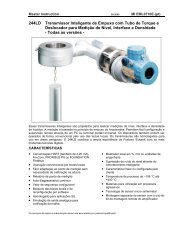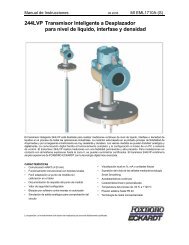
244LVP Intelligent Buoyancy Transmitter for ... - Foxboro Eckardt
244LVP Intelligent Buoyancy Transmitter for ... - Foxboro Eckardt
244LVP Intelligent Buoyancy Transmitter for ... - Foxboro Eckardt

Create successful ePaper yourself
Turn your PDF publications into a flip-book with our unique Google optimized e-Paper software.
14 <strong>244LVP</strong> MI EML1710 A-(en)<br />
8 CALIBRATION OF TRANSMITTER<br />
Zero, lower range value, upper range value and damping of<br />
the transmitter are set by manufacturer as specified in the<br />
order.<br />
There<strong>for</strong>e, calibration at start-up is not necessary.<br />
In case the order does not include this data, the transmitter<br />
is supplied as follows:<br />
displacer weight <strong>for</strong>ce = 1.500 kg<br />
buoyancy = 5.884 N (0.600 kg)<br />
indication = %<br />
damping = 8 sec (63 % time)<br />
Operating data and displacer data are stored in the<br />
transmitter according to the order.<br />
Calibration becomes necessary if this data deviates from<br />
the values stored.<br />
The transmitter is designed <strong>for</strong> a displacer weight <strong>for</strong>ce of<br />
max. 2.5 kg 1) and a buoyancy <strong>for</strong>ce of 2 N to 20 N. The<br />
lower range value F0 must be within the range 2 kg to 2.5<br />
kg. 1)<br />
Calibration of devices via operating push buttons<br />
Calibration can be done by means of the push buttons at<br />
the transmitter if the amplifier housing has<br />
• either external push buttons, see Chap. 8.1<br />
”Calibration via local keys”<br />
• or display with internal push buttons, see Chap. 8.3<br />
“Calibration via display keys”.<br />
Calibration via HART Protocol<br />
• Calibration with Handterminal HT991<br />
• Calibration with PC, Display and User Interface<br />
ABO991/PC20<br />
• Basic calibration with PC and <strong>Transmitter</strong> Service<br />
Program TSP991<br />
(necessary if sensor or amplifier are changed).<br />
1) Attention! 1kg generates a <strong>for</strong>ce of 9.807 N<br />
8.1 Calibration via local keys<br />
Operation and local key functions<br />
The two local keys 1 and 2 are used to set up zero, lower<br />
range value, upper range value and damping.<br />
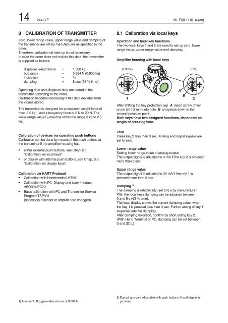
Amplifier housing with local keys<br />
After shifting the key protection cap A insert screw driver<br />
or pin (∅≤3 mm) into hole B and press down to the<br />
second pressure point.<br />
Both keys have two assigned functions, dependent on<br />
length of pressing time.<br />
Zero<br />
Press key 2 less than 3 sec. Analog and digital signale are<br />
set to zero.<br />
Lower range value<br />
Setting lower range value of analog output:<br />
The output signal is adjusted to 4 mA if the key 2 is pressed<br />
more than 5 sec.<br />
Upper range value<br />
The output signal is adjusted to 20 mA if the key 1 is<br />
pressed more than 5 sec.<br />
Damping 2)<br />
The damping is (electrically) set to 8 s by manufacturer.<br />
With the local keys damping can be adjusted between<br />
0and8s(63%time).<br />
The local display shows the current damping value, when<br />
the key 1 is pressed less than 3 sec. Further acting of key 1<br />
stepwise sets the damping.<br />
After damping selection, confirm by short acting key 2.<br />
(With Hand Terminal or PC, damping can be set between<br />
0 and 32 s.)<br />
2) Damping is only adjustable with push buttons if local display is<br />
provided.<br />
)<br />
*