SRD991 Intelligent Positioner with HART ... - Foxboro Eckardt
SRD991 Intelligent Positioner with HART ... - Foxboro Eckardt
SRD991 Intelligent Positioner with HART ... - Foxboro Eckardt

You also want an ePaper? Increase the reach of your titles
YUMPU automatically turns print PDFs into web optimized ePapers that Google loves.
Data Sheet 12.07 DS EVE0105 -(en)<br />
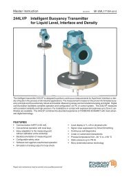
<strong>SRD991</strong> <strong>Intelligent</strong> <strong>Positioner</strong> <strong>with</strong> <strong>HART</strong>, FoxCom,<br />
PROFIBUS-PA, FOUNDATION Fieldbus H1<br />
or Without Communication<br />
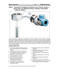
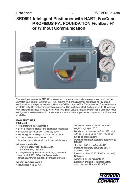
The intelligent positioner <strong>SRD991</strong> is designed to operate pneumatic valve actuators and can be<br />
operated from control systems (e.g. the <strong>Foxboro</strong> I/A Series System), controllers or PC-based<br />
configuration- and operation tools such as the DTMs VALcare or Valve Monitor. The positioner is<br />
available <strong>with</strong> different communication protocols. The multi-lingual full text graphical-LCD (optional<br />
<strong>with</strong> infrared interface), in conjunction <strong>with</strong> the 3 push buttons, allows a comfortable and easy local<br />
configuration and operation. For installations in contact <strong>with</strong> explosive atmospheres, certificates are<br />
available.<br />
MAIN FEATURES<br />
<strong>Intelligent</strong><br />
• Auto-start <strong>with</strong> self-calibration<br />
• Self diagnostics, status- and diagnostic messages<br />
• Easy local operation <strong>with</strong> three key pads<br />
• Multi-Lingual full text graphical LCD, or LEDs<br />
• VALcare or Valve Monitor DTM<br />
for valve diagnostics and predictive maintenance<br />
<strong>with</strong> communication<br />
• <strong>HART</strong>, FOUNDATION Fieldbus H1,<br />
PROFIBUS-PA, FoxCom<br />
• Configuration by means of local keys, handheld<br />
terminal (<strong>HART</strong>), PC or I/A Series system<br />
or <strong>with</strong> an infrared interface by means of IrCom<br />
<strong>with</strong>out communication<br />
• Input signal 4 to 20 mA<br />
• Stroke 8 to 260 mm (0.3 to 10.2 in)<br />
• Angle range up to 95 °<br />
• Supply air pressure up to 6 bar (90 psig),<br />
<strong>with</strong> spool valve up to 7 bar (105 psig)<br />
• Single or double-acting<br />
• Mounting on linear actuators according to<br />
NAMUR<br />
– IEC 534, Part 6 – VDI/VDE 3847<br />
• Mounting on rotary actuators acc. to<br />
VDI/VDE 3845<br />
• Protection class IP 65 (IP 66 on request),<br />
NEMA 4X<br />
• Approved for SIL applications<br />
• Explosion protection: Intrinsic Safety<br />
according to ATEX and FM/CSA
2 <strong>SRD991</strong> DS EVE0105 (en)<br />
FUNCTIONAL SPECIFICATIONS (common data for all versions)<br />
Travel range<br />
Stroke range . . . . . . . . . . . . . . . . . 8…260 mm (0.3 ... 10.2 in) <strong>with</strong> standard feedback levers; special levers on<br />
request<br />
Rotation angle range . . . . . . . . . . . up to 95° (<strong>with</strong>out mechanical stop)<br />
Supply<br />
Supply air pressure . . . . . . . . . . . . 1.4 ... 6 bar (20 ... 90 psig)<br />
<strong>with</strong> spool valve 4) . . . . . . . . . . . . . 1.4 ... 7 bar (20...105psig)<br />
Output to actuator . . . . . . . . . . . . . 0 to ~100 % of supply air pressure (up to 5.5 bar at 6 bar supply air pressure)<br />
Air supply 1) . . . . . . . . . . . . . . . . . . according to ISO 8573-1<br />
Solid particle size and density . . . . class 2<br />
Oil rate . . . . . . . . . . . . . . . . . . . . . . class 3<br />
Response characteristic 2) 3)<br />
Sensitivity . . . . . . . . . . . . . . . . . . . . < 0.1% of travel span<br />
Non-linearity (terminal based adjustment) . . . . . . . . < 0.4 % of travel span<br />
Hysteresis . . . . . . . . . . . . . . . . . . . < 0.3 % of travel span<br />
Supply air dependence. . . . . . . . . . < 0.1 %/ 1 bar (15 psi)<br />
Temperature effect. . . . . . . . . . . . . < 0.3 %/ 10 K<br />
Mechanical vibration 10 to 60 Hz up to 0.14 mm, 60 to 500 Hz up to 2 g . . . . . < 0.25 % of travel span<br />
Air output Nm 3 /h (scfh)<br />
at max. deviation,<br />
SRD single or double acting . . . . . 7.5 Nm 3 /h (265 scfh) @ 6 bar (90 psig)<br />
SRD <strong>with</strong> spool valve amplifier. . . . 18 Nm 3 /h (636 scfh) @ 6 bar (90 psig)<br />
SRD <strong>with</strong> booster code F or G. . . . 21 Nm 3 /h (742 scfh) @ 6 bar (90 psig)<br />
Air consumption (steady state) Nl/h (scfh)<br />
SRD single acting . . . . . . . . . . . . . 150 Nl/h (5.3 scfh) @ 6 bar (90 psig)<br />
SRD double acting . . . . . . . . . . . . .400 Nl/h (14.1 scfh) @ 6 bar (90 psig)<br />
SRD <strong>with</strong> spool valve amplifier . . . . 550 Nl/h (19.4 scfh) @ 6 bar (90 psig)<br />
Operation and Configuration<br />
The local LCD enables a fast and easy configuration as well as clear diagnostic.<br />
Local . . . . . . . . . . . . . . . . . . . . . . . <strong>with</strong> local key pads<br />
Display. . . . . . . . . . . . . . . . . . . . . . Multi-lingual Graphic LCD and five LEDs<br />
PHYSICAL SPECIFICATIONS (common data for all versions)<br />
Mounting<br />
Onto any valve.<br />
Linear Actuator up to 260mm <strong>with</strong> standard feedback lever, for bigger stroke please consults us<br />
Rotary Actuator up to 95° rotation and up to 300° <strong>with</strong> special construction<br />
Materials<br />
Housing and covers . . . . . . . . . . . . Aluminum (Alloy No. 230) finished <strong>with</strong> DD-varnish<br />
All moving parts of feedback system . . . . . . . . . 1.4306 / 1.4571 / 1.4104<br />
Attachment kits . . . . . . . . . . . . . . . V4A or Aluminum, finished <strong>with</strong> DD varnish<br />
(depending upon version) . . . . . . . (Alloy No. 230)<br />
Mounting bracket . . . . . . . . . . . . . . Aluminum (Alloy No. 230)<br />
Pneumatic diaphragms . . . . . . . . . PVMQ (Silicone elastomer, suitable for use in the paint industry)<br />
Weight<br />
Single acting . . . . . . . . . . . . . . . . . approx. 1.7 kg (3.7 lbs)<br />
Double acting. . . . . . . . . . . . . . . . . approx. 2.0 kg (4.4 lbs)<br />
Pneumatic connection<br />
NAMUR mounting . . . . . . . . . . . . . G 1/4 or 1/4-18NPT <strong>with</strong> additional connection manifold
DS EVE0105 (en) <strong>SRD991</strong> 3<br />
Electrical Connection<br />
Line entry. . . . . . . . . . . . . . . . . . . . 1 or 2 cable glands 1/2-14 NPT or M20 x1.5 (others <strong>with</strong> Adapter AD-...)<br />
Cable diameter . . . . . . . . . . . . . . . 6 to 12 mm (0.24 to 0.47 in)<br />
Screw terminals . . . . . . . . . . . . . . . 2 terminals for input, 4 terminals for additional inputs / outputs<br />
Wire cross section . . . . . . . . . . . . . 0.3 to 2.5 mm 2 (AWG 22-14)<br />
Test sockets . . . . . . . . . . . . . . . . . for options and communicator connection<br />
Ambient conditions<br />
Operating conditions . . . . . . . . . . . acc. to IEC 654-1<br />
The device can be operated at a class Dx location<br />
Ambient temperature<br />
Operation 1) . . . . . . . . . . . . . . . . . . –40 ... 80 °C (–40 ... 176 °F)<br />
Transport and storage . . . . . . . . . . –40 ... 80 °C (–40 ... 176 °F)<br />
Storage conditions acc. to IEC60721-3-1: . . . . . . . . . . . . . . . . . . . . . . . 1K5; 1B1; 1C2; 1S3; 1M2<br />
Indicators<br />
LCD (visible) 2) . . . . . . . . . . . . . . . . –25 ... 70 °C (–13 ... 176 °F)<br />
LEDs . . . . . . . . . . . . . . . . . . . . . . . –40 ... 80 °C (–40 ... 176 °F)<br />
Relative humidity . . . . . . . . . . . . . . up to 100 %<br />
Protection class 3)<br />
acc. to IEC529. . . . . . . . . . . . . . . . IP 65; IP 66 on request<br />
acc. to NEMA. . . . . . . . . . . . . . . . . Type 4X<br />
Electromagnetic compatibility EMC<br />
Operating conditions . . . . . . . . . . . industrial environment<br />
Immunity according to<br />
EN61326 . . . . . . . . . . . . . . . . . . . . fulfilled<br />
IEC 61326 . . . . . . . . . . . . . . . . . . . fulfilled<br />
EN61000-6-2 . . . . . . . . . . . . . . . . . fulfilled<br />
Emission according to EN 61326 Class A and Class B. . . . . . . . . . . . . fulfilled<br />
EN61000-6-4 . . . . . . . . . . . . . . . . . fulfilled<br />
EN 55011 Group 1, Class A and Class B. . . . . . . . . . . . . . . . . . . . . . . . fulfilled<br />
NAMUR recommendation EMVNE21. . . . . . . . . . . . . . . . . . . . . . . . . . . fulfilled<br />
SAFETY REQUIREMENTS<br />
CE label<br />
Electromagnetic compatibility 4) . . . 89/336/EWG<br />
Low-voltage regulation. . . . . . . . . . 73/23/EWGnot applicable<br />
Safety<br />
According to EN 61010-1 (or IEC1010-1) . . . . . . . . . . . . . . . . . . . . . . . Safety class III<br />
Overvoltage Category I<br />
Internal fuses. . . . . . . . . . . . . . . . . only <strong>with</strong> PROFIBUS or FOUNDATION Fieldbus, but not replaceable<br />
External fuses . . . . . . . . . . . . . . . . Limitation of power supplies<br />
for fire protection must be observed acc. to EN 61010-1, appendix F (bzw. IEC 1010-1).<br />
1) Details see Certificates of Conformity. With Option -T only –20 °C<br />
2) Below –20 °C the LCD reacts only slowly; above +70°C the background becomes dark<br />
3) Under service as directed<br />
4) With PROFIBUS or FOUNDATION Fieldbus only, if shield of wiring is grounded on both sides
4 <strong>SRD991</strong> DS EVE0105 (en)<br />
Electrical classification 4) 5)<br />
see Certificates of Conformity EX EVE0105 A<br />
Type of protection “Intrinsically Safe”<br />
Type AI 638. . . . . . . . . . . . . . . . . . II 2GEEx ia IIB/IIC, II 2 G EEx ib IIB/IIC<br />
FM Type of protection<br />
IS / I, II, III / 1/ ABCDEFG / T4 Ta = 80°C- Entity; Type 4X; DOKZ 534 396 058<br />
NI / I / 2/ ABCD; S / II,III / FG / T4 Ta = 80°C; Type 4X; IS / I,II,III / 1 / ABCDFG / T4 Ta = 55°C; Entity; Type 4X;<br />
DOKZ 534 396 049<br />
NI / I / 2 / ABCD; S / II,III / 2 / FG / T4 Ta = 80°C, T6 Ta =55°C; Type 4X<br />
CSA Type of protection “Intrinsic Safety / Non-Incendive”<br />
Class I. Groups A, B, C and D: Class II. Groups E, F and G:<br />
Class III:<br />
Ex ia IIC T4/T6 IP65:<br />
<strong>HART</strong> / 4 - 20mA / FOXCOM/Profibus/Fieldbus -abbcdefg-j <strong>Positioner</strong>: 12-36 Vdc. 4-20 mA or 48 Vdc, Intrinsically<br />
Safe when installed as per submittor’s drawings DOKZ 534 396 067 or DOKZ 534 396 076 : Temp. Code T4 at<br />
max amb. 80°C or T6 at max. amb. 55°C<br />
Class I. Div 2. Groups A. B. C and D: Class II. Div 2. Group F and G: Class III. Div 2: IP65 End<br />
COMMUNICATION VERSION<br />
<strong>SRD991</strong> <strong>with</strong>out communication - <strong>SRD991</strong>-xDxxxx<br />
Signal Input . . . . . . . . . . . . . . . . . . Two wire system<br />
Signal range . . . . . . . . . . . . . . . . . . 4 to 20 mA<br />
<strong>SRD991</strong> <strong>with</strong> <strong>HART</strong> communication - <strong>SRD991</strong>-xHxxxx<br />
Signal Input . . . . . . . . . . . . . . . . . . Two wire system<br />
Signal range . . . . . . . . . . . . . . . . . 4 to 20 mA<br />
<strong>SRD991</strong> <strong>with</strong> FoxCom communication - <strong>SRD991</strong>-xFxxxx<br />
FoxCom is a digital communication protocol of <strong>Foxboro</strong>.<br />
Input . . . . . . . . . . . . . . . . . . . . . . . . Two-wire system, digital<br />
Supply voltage. . . . . . . . . . . . . . . . DC8 to 36 V<br />
Supply current . . . . . . . . . . . . . . . . ~ 9 mA at 24 V<br />
<strong>SRD991</strong> <strong>with</strong> communication PROFIBUS-PA - <strong>SRD991</strong>-xPxxxx<br />
Operating current. . . . . . . . . . . . . . 10.5 mA ± 0.5 mA (base current)<br />
Current amplitude . . . . . . . . . . . . . ± 8 mA<br />
Fault current. . . . . . . . . . . . . . . . . . base current + 0 mA<br />
(base current + 4 mA by means of independent FDE-safety circuit) according to IEC 1158-2<br />
Data transfer . . . . . . . . . . . . . . . . . according to PROFIBUS- PA profile class B based on EN 50170<br />
and DIN 19245 part 4<br />
<strong>SRD991</strong> <strong>with</strong> communication FOUNDATION Fieldbus H1<br />
<strong>SRD991</strong>-xQxxxx<br />
Operating current. . . . . . . . . . . . . . 10.5 mA ± 0.5 mA (base current)<br />
Current amplitude . . . . . . . . . . . . . . ± 8 mA<br />
Fault current. . . . . . . . . . . . . . . . . . base current + 0mA<br />
(base current + 4 mA by means of independent FDE-safety circuit) according to IEC 1158-2<br />
Data transfer . . . . . . . . . . . . . . . . . FF Specification Rev. 1.4,<br />
Link-Master (LAS)<br />
Certified according to . . . . . . . . . . ITK 4.6<br />
Function Blocks . . . . . . . . . . . . . . . PID, AO, 2xDI, 1xDO, Transducer, Resource<br />
4) With appropriate order only<br />
5) National requirements must be observed
DS EVE0105 (en) <strong>SRD991</strong> 5<br />
ADDITIONAL EQUIPMENT (built into any basic device)<br />
Built-in Pressure sensors 50, Code Option –B<br />
For supply air and output y1 to actuator<br />
Measuring range . . . . . . . . . 0 to 8 bar (0 to 120 psig)<br />
Accuracy . . . . . . . . . . . . . . . 0.5 %<br />
Temperature influence . . . . . 0.5 %/ 10k (–40 to 80°C)<br />
Additional Inputs / Outputs:<br />
One module “Additional inputs / outputs” 8 can be plugged<br />
onto main electronics 40 :<br />
• Position feedback and Alarm or<br />
• 2 Binary outputs or<br />
• 2 Binary inputs or<br />
• Potentiometer input<br />
Built-in Limit Switch<br />
Built-in Limit signal switch B<br />
Stroke / angle derived from positioner feedback.<br />
– inductive NAMUR standard version (SJ2-N)<br />
– inductive NAMUR security version (SJ2-SN)<br />
– inductive 3-wire (SI2-K08-AP7/ PNP)<br />
– Micro switches<br />
.
6 <strong>SRD991</strong> DS EVE0105 (en)<br />
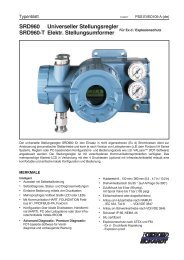
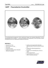
FUNCTIONAL DESIGNATIONS<br />
1a Adapter, eg. 1/2”-14 NPT<br />
1b Cable gland<br />
2 Plug, interchangeable <strong>with</strong> Pos.1<br />
3 Screw terminals 1) (11 / 12) for input (w) or<br />
for bus connection IEC 1158-2<br />
3a Screw terminals 1) for additional inputs / outputs<br />
3b Test sockets Ø 2 mm, integrated in terminal block<br />
4 Ground connection<br />
5 Female thread G 1/4 for output I (y1)<br />
6 Female thread G 1/4 for air supply (s)<br />
7 Female thread G 1/4 for output II (y2)<br />
8 Direct attachment hole for output I (y1)<br />
9 Feedback shaft<br />
10 Connection manifold for attachment to stroke actuators<br />
(not <strong>with</strong> VDI/VDE 3847 version)<br />
11 Connection base for attachment to rotary actuators<br />
12 Travel indicator<br />
1) Alternatively WAGO terminals instead of screw terminals<br />
13 Key UP<br />
14 Key DOWN<br />
15 Key M (Menu)<br />
16 Status display (1 red LED, 4 green LEDs)<br />
16a LCD <strong>with</strong> true text in 3 different languages<br />
19 Fixing shaft for limit switch<br />
20 Cover <strong>with</strong> window to 12<br />
21 Air vent, dust and water protected<br />
22 Data label<br />
26 Arrow is perpendicular to shaft 9 at angle 0<br />
degree<br />
28 High cover <strong>with</strong> built-in limit switch<br />
29 Plug for service connector<br />
30 IrCom interface
DS EVE0105 (en) <strong>SRD991</strong> 7<br />
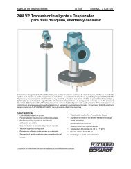
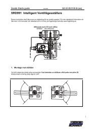
DIMENSION
8 <strong>SRD991</strong> DS EVE0105 (en)<br />
Subject to alterations - reprinting, copying and translation prohibited. Products and publications are<br />
normally quoted here <strong>with</strong>out reference to existing patents, registered utility models or trademarks.<br />
The lack of any such reference does not justify the assumption that a product or symbol is free.<br />
FOXBORO ECKARDT GmbH ECKARDT S.A.S.<br />
Pragstrasse 82 20 rue de la Marne<br />
D-70376 Stuttgart F-68360 Soultz<br />
Germany France<br />
Tel. + 49(0)711 502-0 Tel. + 33 (0)3 89 62 15 30<br />
Fax + 49(0)711 502-597 Fax + 33 (0)3 89 62 14 85<br />
http://www.foxboro-eckardt.com http://www.eckardt.fr<br />
http://www.foxboro-eckardt.de