Fan-coil valves Series 2131 - 3131 - 4131 - Totaline
Fan-coil valves Series 2131 - 3131 - 4131 - Totaline
Fan-coil valves Series 2131 - 3131 - 4131 - Totaline

You also want an ePaper? Increase the reach of your titles
YUMPU automatically turns print PDFs into web optimized ePapers that Google loves.
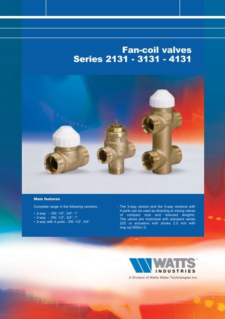
Main features<br />
Complete range in the following versions :<br />
• 2-way - DN: 1/2”, 3/4”, 1”<br />
• 3-way - DN: 1/2”, 3/4”, 1”<br />
• 3-way with 4 ports - DN: 1/2”, 3/4”<br />
<strong>Fan</strong>-<strong>coil</strong> <strong>valves</strong><br />
<strong>Series</strong> <strong>2131</strong> - <strong>3131</strong> - <strong>4131</strong><br />
- The 3-way version and the 3-way versions with<br />
4 ports can be used as diverting or mixing <strong>valves</strong><br />
of compact size and reduced weights.<br />
The <strong>valves</strong> are motorized with actuators series<br />
22C or actuators with stroke 2.5 mm with<br />
ring nut M30x1.5.<br />
A Division of Watts Water Technologies Inc.
2<br />
Description<br />
FAN-COIL VALVES<br />
<strong>Fan</strong>-<strong>coil</strong> control <strong>valves</strong> series <strong>2131</strong>, <strong>3131</strong>, <strong>4131</strong> are used for controlling the flow of hot or cold water in heating<br />
and air conditioning systems. They are operated by electric actuators with max. stroke of 2.5 mm. such as<br />
electrothermic actuator series 22C.<br />
As standard, the <strong>valves</strong> are available in the configuration with male thread in the following versions :<br />
• 2-way series <strong>2131</strong><br />
• 3-way series <strong>3131</strong><br />
• 3-way with 4 ports series <strong>4131</strong> with built-in by-pass.<br />
Operation of the valve plug is by electrothermic actuator series 22C, available in the following versions:<br />
• NO (normally open) 2-wire(Standard) or 4-wire (with auxiliary microswitch contact)<br />
• NC (normally closed) 2-wire (Standard) or 4-wire (with auxiliary microswitch contact)<br />
All actuators of the 22C series can easily be fastened to the valve body with a threaded ring nut. (M30x1.5).<br />
<strong>2131</strong><br />
Two-way brass valve for fan-<strong>coil</strong>s.<br />
ON/OFF operation with actuators series 22C.<br />
Max. operating temperature: 100°C. Disc stroke: 2.5 mm.<br />
Nominal pressure: 16 bar.<br />
Type Part number Dn Kvs Weight (g)<br />
<strong>2131</strong> <strong>2131</strong>12 1/2" MM 1,7 200<br />
<strong>2131</strong> <strong>2131</strong>34 3/4" MM 2,8 200<br />
<strong>2131</strong> <strong>2131</strong>1 1" MM 4,5 500<br />
<strong>3131</strong><br />
Three-way brass valve for fan-<strong>coil</strong>s. ON/OFF operation with actuators series 22C.<br />
Max. operating temperature: 100°C. Disc stroke: 2.5 mm. Can be used both as<br />
mixing and diverting valve, except for version <strong>3131</strong>1 which can only be used as<br />
diverting valve. Nominal pressure: 16 bar.<br />
The Kvs and by-pass Kvs values given in the table alongside refer to the valve<br />
used for diverting service.<br />
Type Part number Dn Kvs Kvs By-bass Weight (g)<br />
<strong>3131</strong> <strong>3131</strong>12 1/2" MM 1,7 1,3 200<br />
<strong>3131</strong> <strong>3131</strong>34 3/4" MM 2,8 1,8 250<br />
<strong>3131</strong> <strong>3131</strong>1 1" MM 4,5 3,1 550<br />
VU<br />
Tee fitting for creating by-pass in <strong>valves</strong> series <strong>3131</strong> (Dn 1“).<br />
Type Part number Dn Weight (g)<br />
VU VU311 1" MM 250
Application<br />
FAN-COIL VALVES<br />
The <strong>valves</strong> are used for shutting off (series <strong>2131</strong>, two-way) or diverting/mixing (series <strong>3131</strong> - <strong>4131</strong>, 3-way and<br />
3-way with 4 ports size 1/2” e 3/4”), the heat transfer fluid to a heating or air conditioning system as required by<br />
the room thermostat (or timing thermostat).<br />
The 3-way fan-<strong>coil</strong> <strong>valves</strong> series <strong>3131</strong> or 3-way with 4 ports series <strong>4131</strong>, thanks to the special configuration of<br />
the plug controlling the by-pass flow, can be used equally well as diverting or mixing <strong>valves</strong> (thus optimizing to the<br />
full the various plumbing requirements in assembly).<br />
Diverting<br />
Mixing<br />
<strong>4131</strong><br />
Three-way brass valve with 4 connections for fan-<strong>coil</strong>s. ON/OFF operation with<br />
actuators series 22C. Max. operating temperature: 100°C. Disc stroke: 2.5 mm.<br />
Can be used both as mixing and diverting valve. Nominal pressure: 16 bar.<br />
The Kvs and by-pass Kvs values given in the table alongside refer to the valve<br />
used for diverting service.<br />
Type Part number Dn Kvs Kvs By-bass Weight (g)<br />
<strong>4131</strong> <strong>4131</strong>12 1/2" MM 1,7 1,3 350<br />
<strong>4131</strong> <strong>4131</strong>34 3/4" MM 2,8 1,8 400<br />
840<br />
Soft sealed union with nut for zone <strong>valves</strong> series <strong>2131</strong>, <strong>3131</strong>, <strong>4131</strong>.<br />
Type Part number Dn Weight (g)<br />
840 8401212GAS 1/2" x 1/2" 50<br />
840 8403434GAS 3/4" x 3/4" 50<br />
840 84011GAS 1" x 1" 50<br />
AB<br />
AB<br />
B<br />
B<br />
A<br />
A<br />
3
4<br />
Operation<br />
FAN-COIL VALVES<br />
Operation of the fan-<strong>coil</strong> control <strong>valves</strong> <strong>2131</strong>,<strong>3131</strong>,<strong>4131</strong> is through the movement of the plug which shuts off the<br />
heat transfer fluid: the ON/OFF action of the plug is controlled by the actuator series 22C whose internal motor<br />
consists of a wax thermostatic element activated by a PTC thermistor against a signal sent by a room thermostat<br />
(or timing thermostat). The electrochemical actuator series 22C, in the 4-wire version, is provided with an<br />
auxiliary contact for additional controls (metering, control of pumps, fans or other equipment). The mechanical<br />
characteristic of the <strong>valves</strong> is of the Normally Open type. It can be adjusted or fully closed by manually turning the<br />
threaded plastic cap, provided on the valve. This threaded cap acts directly on the valve stem.<br />
When coupled to the 22C NC actuator, under rest conditions (actuator not energized), the valve becomes<br />
• normally closed (NC) (straight way closed and by-pass open if 3-way type); when the actuator is energized,<br />
the valve is opened.<br />
When coupled to the 22C NA actuator, under rest conditions (actuator not energized), the valve remains<br />
• normally open (NO) (straight way open and by-pass closed if 3-way type); when the actuator is energized,<br />
the valve is closed.<br />
The hydraulic flow rate and pressure drops characteristics of the <strong>valves</strong> are given in appropriate charts; instead,<br />
when coupled with the ON/OFF actuators, they assume the characteristics associated with such device.<br />
The three-way <strong>valves</strong> (or three-way <strong>valves</strong> with 4 ports) are designed and built to be used both as diverting <strong>valves</strong><br />
(one inlet and two outlets) and mixing <strong>valves</strong> (two inlets and one outlet). It is recommended to observe the<br />
operating �Pmax given in the table in order to avoid risk of malfunctions and/or noise.<br />
The reliability of the fan-<strong>coil</strong> control <strong>valves</strong> <strong>2131</strong>, <strong>3131</strong>, <strong>4131</strong> is guaranteed by the 100% testing on the<br />
production, which checks the hydraulic seals of the valve body and its components towards the outside and the<br />
seal of the plug in its flow shut-off function.<br />
Design features<br />
Body Brass CW617N<br />
Stem Brass with chemical nickel-plating<br />
Spring Stainless steel<br />
Plug rubber EPDM<br />
Technical features common to the entire range<br />
Max pressure, models w. constant Kv 16 bar<br />
Max pressure, models w. variable Kv 10 bar<br />
Min. fluid temperature 4°C<br />
Max. fluid temperature 110°C<br />
Liquids which can be used Water (with glycol � 50%)<br />
Plug stroke 2.5 mm<br />
By-pass leakage � 0,02 % Kvs<br />
Actuator connection Threaded ring nut M30 x 1.5<br />
Installation<br />
Choice of the fan-<strong>coil</strong> control <strong>valves</strong> depends on the type of plumbing systems as well as the required flow rate<br />
and pressure drop characteristics.<br />
In systems with 2-way control <strong>valves</strong> it is advisable to provide by-pass <strong>valves</strong> series 466 to ensure a minimum<br />
recirculation of the fluid.<br />
Before mounting the <strong>valves</strong>, make sure that the piping is clean, and free from welding slag or the like.<br />
It is recommended not to install the valve with the 22C actuator facing down.<br />
The <strong>valves</strong> can be connected by using the soft-sealed tailpieces series 840 with the range of single-piece<br />
or union fittings (3-piece).<br />
The 1” three-way <strong>valves</strong> can use the TEE fitting (part No. VU311 - DN 1”) for making the by-pass.
Hydraulic characteristics<br />
Valve part number<br />
DN Inches<br />
DN mm<br />
Pre-setting (Kv adjustable)<br />
Port size<br />
• Red part numbers are standard versions<br />
Max. operation pressure<br />
PN [bar]<br />
Kvs<br />
Kv by-pass<br />
��Pmax<br />
Max. differential<br />
operation pressure.<br />
(noise < 38 dBA)<br />
[bar]<br />
FAN-COIL VALVES<br />
��Ps<br />
Close off with actuator<br />
22C NO/NC<br />
[bar]<br />
Kvs<br />
• KVs = nominal value of the flow in the main way of the valve in m3/h with the valve fully open at a pressure of<br />
1 bar and with water temperature at 20 °C<br />
• �Pmax = maximum dynamic differential pressure at the ends of the fully open valve, without risk of noise<br />
( < 38 dBA)<br />
• �Ps= maximum static differential pressure at the ends of the valve against which the valve is able to be opened<br />
(through its internal spring for the three-way versions; through the actuator for the two-way versions)<br />
Kv by-pass<br />
��Pmax<br />
Max. differential<br />
operation pressure.<br />
(noise < 38 dBA)<br />
[bar]<br />
2 WAY VALVES<br />
<strong>2131</strong>12 1/2" 15 15A2 16 1,7 - 0,8 2,5 - - - -<br />
<strong>2131</strong>12P 1/2" 15 15F2 16 1,7 - 0,8 2,5 - - - -<br />
<strong>2131</strong>12DP 1/2" 15 15A2 1,7 - 0,8 4 - - - -<br />
<strong>2131</strong>34 3/4" 20 20A2 16 2,8 - 0,7 1,5 - - - -<br />
<strong>2131</strong>34P 3/4" 20 20F2 16 2,6 - 0,7 1,5 - - - -<br />
<strong>2131</strong>34DP 3/4" 20 20A2 16 2,8 - 0,7 4 - - - -<br />
<strong>2131</strong>1 1" 25 25A2 16 4,5 - 0,6 0,7 - - - -<br />
<strong>2131</strong>1P 1" 25 25F2 16 4,5 - 0,6 0,7 - - - -<br />
<strong>2131</strong>1DP 1" 25 25A2 16 4,5 - 0,6 4 - - - -<br />
��Ps<br />
Close off with actuator<br />
22C NO/NC<br />
[bar]<br />
3 WAY VALVES Used as DIVERTER VALVE Used as MIXING VALVE<br />
<strong>3131</strong>12 1/2" 15 15A3 16 1,7 1,3 0,8 2,5 1,7 1,2 0,7 2<br />
<strong>3131</strong>12P 1/2" 15 15F3 16 1,7 1,3 0,8 2,5 1,7 1,2 0,7 2<br />
<strong>3131</strong>12DP 1/2" 15 15A3 16 1,7 1,3 0,8 4 1,7 1,2 0,7 4<br />
<strong>3131</strong>34 3/4" 20 20A3 16 2,8 1,8 0,7 1,5 2,5 1,6 0,5 1<br />
<strong>3131</strong>34P 3/4" 20 20F3 16 2,8 1,8 0,7 1,5 2,5 1,6 0,5 1<br />
<strong>3131</strong>34DP 3/4" 20 20A3 16 2,8 1,8 0,7 4 2,5 1,6 0,5 1<br />
<strong>3131</strong>1 1" 25 25A3 16 4,5 3,1 0,6 0,7 4,5 3,1 0,4 0,7<br />
<strong>3131</strong>1P 1" 25 25F3 16 4,5 3,1 0,6 0,7 4,5 3,1 0,4 0,7<br />
<strong>3131</strong>1DP 1" 25 25A3 16 4,5 3,1 0,6 4 4,5 3,1 0,4 4<br />
3 WAY VALVES 4 PORT Used as DIVERTER VALVE Used as MIXING VALVE<br />
<strong>4131</strong>12 1/2" 15 15A4 16 1,7 1,3 0,8 2,5 1,7 1,2 0,7 2<br />
<strong>4131</strong>12P 1/2" 15 15F4 16 1,7 1,3 0,8 2,5 1,7 1,2 0,7 2<br />
<strong>4131</strong>1240P 1/2" 15 15I4 16 1,7 1,3 0,8 2,5 1,7 1,2 0,7 2<br />
<strong>4131</strong>12DP 1/2" 15 15A4 16 1,7 1,3 0,8 4 1,7 1,2 0,7 4<br />
<strong>4131</strong>34 3/4" 20 20A4 16 2,8 1,8 0,7 1,5 2,5 1,6 0,5 1<br />
<strong>4131</strong>34P 3/4" 20 20F4 16 2,6 1,8 0,7 1,5 2,5 1,6 0,5 1<br />
<strong>4131</strong>34DP 3/4" 20 20A4 16 2,8 1,8 0,7 4 2,5 1,6 0,5 4<br />
<strong>4131</strong>3440P 3/4" 20 20I4 16 2,8 1,8 0,7 1,5 2,5 1,6 0,5 1<br />
5
6<br />
DN<br />
FAN-COIL VALVES<br />
Overall dimensions (mm)<br />
<strong>2131</strong><br />
A<br />
B C<br />
D<br />
Part number DN A B C D<br />
<strong>2131</strong>12 1/2” 52 29 13,5 51<br />
<strong>2131</strong>12P 1/2” 52 29 13,5 51<br />
<strong>2131</strong>12DP 1/2” 52 29 13,5 51<br />
<strong>2131</strong>34 3/4” 56 28 13,5 56<br />
<strong>2131</strong>34P 3/4” 56 28 13,5 56<br />
<strong>2131</strong>34DP 3/4” 56 28 13,5 56<br />
<strong>2131</strong>1 1” 82 30,5 13,5 77,5<br />
<strong>2131</strong>1P 1” 82 30,5 13,5 77,5<br />
<strong>2131</strong>1DP 1” 82 30,5 13,5 77,5<br />
<strong>4131</strong><br />
DN<br />
A<br />
<strong>3131</strong><br />
DN<br />
Part number DN A B C D E<br />
<strong>4131</strong>12 1/2” 52 29 13,5 95,5 35<br />
<strong>4131</strong>12P 1/2” 52 29 13,5 95,5 35<br />
<strong>4131</strong>12DP 1/2” 52 29 13,5 95,5 35<br />
<strong>4131</strong>1240P 1/2” 52 29 13,5 100,5 40<br />
<strong>4131</strong>3440P 3/4” 56 28 13,5 102,5 40<br />
<strong>4131</strong>34 3/4” 56 28 13,5 112,5 50<br />
<strong>4131</strong>34P 3/4” 56 28 13,5 112,5 50<br />
<strong>4131</strong>34DP 3/4” 56 28 13,5 112,5 50<br />
A<br />
B C<br />
D<br />
Part number DN A B C D<br />
<strong>3131</strong>12 1/2” 52 29 13,5 68,5<br />
<strong>3131</strong>12P 1/2” 52 29 13,5 68,5<br />
<strong>3131</strong>12DP 1/2” 52 29 13,5 68,5<br />
<strong>3131</strong>34 3/4” 56 28 13,5 69,5<br />
<strong>3131</strong>34P 3/4” 56 28 13,5 69,5<br />
<strong>3131</strong>34DP 3/4” 56 28 13,5 69,5<br />
<strong>3131</strong>1 1” 82 38 13,5 92,5<br />
<strong>3131</strong>1P 1” 82 38 13,5 92,5<br />
<strong>3131</strong>1DP 1” 82 38 13,5 92,5<br />
C<br />
E B<br />
D
Connections dimensions (mm)<br />
15F2<br />
G 1/2<br />
20F2<br />
G 3/4<br />
Ø19.5<br />
25A2<br />
G 1<br />
Ø26<br />
1.5<br />
Ø13.8 +0.1<br />
0<br />
45°<br />
10<br />
17.2<br />
12.5 18<br />
12 21.5<br />
G 1<br />
15A2<br />
G1/2<br />
20A2<br />
G 3/4<br />
Ø14.5 +0.1<br />
0<br />
45°<br />
Ø20.5<br />
25F2<br />
Ø24<br />
45°<br />
1.5<br />
1.5<br />
FAN-COIL VALVES<br />
10<br />
10<br />
12.7<br />
14.5<br />
12 21.5<br />
7
8<br />
15A3<br />
G 1/2<br />
Ø14.5 +0.1<br />
0<br />
20A3<br />
G 1<br />
G 3/4<br />
Ø20.5<br />
25A3<br />
Ø26<br />
1.5<br />
FAN-COIL VALVES<br />
1.5<br />
1.5<br />
45°<br />
10 12.7<br />
45°<br />
10<br />
10<br />
9.5<br />
14.5<br />
12 21.5<br />
12<br />
45°<br />
15F3<br />
G 1/2<br />
20F3<br />
G 3/4<br />
25F3<br />
G 1<br />
Ø24<br />
Ø13.8 +0.1<br />
0<br />
Ø19.5<br />
10<br />
12.5<br />
15.9<br />
14.1<br />
17.2<br />
18<br />
12 21.5<br />
12
15A4<br />
15I4<br />
20F4<br />
G 1/2<br />
G 1/2<br />
G 3/4<br />
Ø14.5 +0.1<br />
0<br />
Ø13.8 +0.1<br />
0<br />
Ø19.5<br />
45°<br />
10<br />
1.5<br />
10<br />
13.5<br />
17.2<br />
12.5 18<br />
12.7<br />
12.7<br />
40<br />
50<br />
35<br />
15F4<br />
G 1/2<br />
20A4<br />
G 3/4<br />
20I4<br />
G 3/4<br />
Ø13.8 +0.1<br />
0<br />
Ø19.5<br />
Ø20.5<br />
1.5<br />
FAN-COIL VALVES<br />
10<br />
45°<br />
10<br />
15<br />
17.2<br />
12.5 18<br />
14.5<br />
15<br />
35<br />
50<br />
40<br />
9
8<br />
FAN-COIL VALVES<br />
Flow rate/pressure drop charts<br />
<strong>2131</strong> - <strong>3131</strong> - <strong>4131</strong> DN 1/2 "<br />
PRESSURE DROP<br />
PRESSURE DROP<br />
[ kPa ]<br />
20<br />
10<br />
8<br />
5<br />
4<br />
3<br />
2<br />
1<br />
0.8<br />
0.5<br />
0.3<br />
0.2<br />
0.1<br />
1<br />
10 20 30 50 100 200 300 500 1000 2000 3000 [ l/h ]<br />
[ kPa ]<br />
Straight way Diverting + Mixing Kv 1,7<br />
by-pass Diverting Kv 1,3<br />
by-pass Mixing Kv 1,2<br />
0.01 0.02 0.03 0.05 0.1 0.2 0.3 0.5 1 2 3<br />
FLOW RATE<br />
0.01 0.02 0.03 0.05 0.1 0.2 0.3 0.5 1 2 3<br />
FLOW RATE<br />
[ m bar ] [ mm c.a. ]<br />
200<br />
100<br />
80<br />
50<br />
40<br />
30<br />
20<br />
10<br />
5<br />
3<br />
2<br />
3 [ m /h ]<br />
<strong>2131</strong> - <strong>3131</strong> - <strong>4131</strong> DN 3/4 "<br />
20<br />
10<br />
8<br />
5<br />
4<br />
3<br />
2<br />
1<br />
0.8<br />
0.5<br />
0.3<br />
0.2<br />
Straight way Diverting Kv 2,8<br />
Straight way Mxing Kv 2,5<br />
by-pass Diverting Kv 1,8<br />
by-pass Mixing Kv 1,6<br />
0.1<br />
1<br />
10 20 30 50 100 200 300 500 1000 2000 3000 [ l/h ]<br />
3 [ m /h ]<br />
2000<br />
1000<br />
800<br />
500<br />
400<br />
300<br />
200<br />
100<br />
50<br />
30<br />
20<br />
10<br />
[ m bar ] [ mm c.a. ]<br />
200<br />
100<br />
80<br />
50<br />
40<br />
30<br />
20<br />
10<br />
5<br />
3<br />
2<br />
2000<br />
1000<br />
800<br />
500<br />
400<br />
300<br />
200<br />
100<br />
50<br />
30<br />
20<br />
10
Flow rate/pressure drop charts<br />
PRESSURE DROP<br />
[ kPa ]<br />
0.01 0.02 0.03 0.05 0.1 0.2 0.3 0.5 1 2 3<br />
FLOW RATE<br />
FAN-COIL VALVES<br />
<strong>2131</strong> - <strong>3131</strong> DN 1 "<br />
20<br />
10<br />
8<br />
5<br />
4<br />
3<br />
2<br />
1<br />
0.8<br />
0.5<br />
0.3<br />
0.2<br />
Straight Way Diverting - Mixing Kv 4,5<br />
by-pass Kv 3,1<br />
0.1<br />
1<br />
10 20 30 50 100 200 300 500 1000 2000 3000 [ l/h ]<br />
[ m bar ] [ mm c.a. ]<br />
200<br />
100<br />
3 [ m /h ]<br />
The descriptions and photographs contained in this brochure are supplied by way of information only and are not binding.<br />
Watts Industries reserves the right to carry out any technical and aesthetic modifications to its products without prior notice.<br />
80<br />
50<br />
40<br />
30<br />
20<br />
10<br />
5<br />
3<br />
2<br />
2000<br />
1000<br />
800<br />
500<br />
400<br />
300<br />
200<br />
100<br />
50<br />
30<br />
20<br />
10<br />
9
Re-order no. 69-0015-UK-IT/1-07-01-Rev.0<br />
Product range Watts Industries<br />
- System disconnectors<br />
- Backflow protection devices<br />
- Check <strong>valves</strong><br />
- Safety units<br />
- Safety relief <strong>valves</strong><br />
- Pressure reducing <strong>valves</strong><br />
- Automatic control <strong>valves</strong><br />
- Butterfly <strong>valves</strong><br />
- Shut off <strong>valves</strong><br />
- Measuring gauges<br />
- Temperature control<br />
- Expansion vessels<br />
- Process switches<br />
- Fuel products<br />
- Gas products<br />
- Electronic controls<br />
- Installation protection products<br />
- Radiator <strong>valves</strong><br />
- System products<br />
- Manifolds and fittings<br />
A Division of Watts Water Technologies Inc.<br />
Watts Industries Italia S.r.l.<br />
Via Brenno, 21 - 20046 Biassono (MI), Italia<br />
Ph. +39 039 4986.1 - Fax +39 039 4986.222<br />
e-mail : info@wattsindustries.it - www.wattsindustries.com