LGA Burner Control
LGA Burner Control
LGA Burner Control

You also want an ePaper? Increase the reach of your titles
YUMPU automatically turns print PDFs into web optimized ePapers that Google loves.
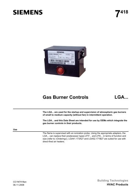
7 418<br />
Gas <strong>Burner</strong> <strong>Control</strong>s<br />
<strong>LGA</strong>...<br />
The <strong>LGA</strong>... are used for the startup and supervision of atmospheric gas burners<br />
of small to medium capacity (without fan) in intermittent operation.<br />
The <strong>LGA</strong>... and this Data Sheet are intended for use by OEMs which integrate the<br />
gas burner controls in their products.<br />
Use<br />
The flame is supervised with an ionization probe. Using the appropriate adapters, the<br />
<strong>LGA</strong>... can replace their predecessor types LFI7... and LFI5... in terms of function and<br />
size (refer to «Ordering»). <strong>LGA</strong>41.173A27 and <strong>LGA</strong>52.171B27 are suited for use with<br />
direct-fired air heaters.<br />
CC1N7418en<br />
06.11.2008<br />
Building Technologies<br />
HVAC Products
Warning notes<br />
To avoid injury to persons, damage to property and the environment, the following<br />
warning notes must be observed!<br />
Do not open, interfere with or modify the unit.<br />
• All activities (mounting, installation and service work, etc.) must be performed by<br />
qualified staff<br />
• Before making any wiring changes in the connection area, completely isolate the<br />
plant from mains supply (all-polar disconnection). Ensure that the plant cannot be<br />
inadvertently switched on again and that it is indeed dead. If not observed, there is<br />
a risk of electric shock hazard<br />
• Ensure protection against electric shock hazard by providing appropriate protection<br />
for the burner control’s connections terminals<br />
• Each time work has been carried out (mounting, installation, service work, etc.),<br />
check to ensure that wiring is in an orderly state and make the safety checks as<br />
described in «Commissioning notes»<br />
• Press the lockout reset button / operating button only manually (applying a force of<br />
no more than 60 N), without using any tools or pointed objects<br />
• Fall or shock can adversely affect the safety functions. Such units must not be put<br />
into operation even if they do not exhibit any damage<br />
Mounting notes<br />
Sitting the ionization<br />
probe<br />
• Ensure that the relevant national safety regulations are complied with<br />
• The ionization probe and ignition electrode must be positioned such that the ignition<br />
spark cannot arc over to the ionization probe<br />
• The position and polarity of the ignition electrode can adversely affect the magnitude<br />
of the flame signal. Reversal of polarity of the ignition transformer’s connections<br />
on the primary side usually solves the problem<br />
• Since the burner bars form the earthed counter-electrode, the burner must be adjusted<br />
such that the flame is hot and stable and in firm contact with the burner bars.<br />
With pulsating flames or yellow-burning flames resulting from lack of air, a very low<br />
or even no ionization current is generated so that the burner control will initiate<br />
lockout<br />
2/12<br />
Building Technologies<br />
CC1N7418en<br />
HVAC Products 06.11.2008
Installation notes<br />
Only with <strong>LGA</strong>41...<br />
Only with <strong>LGA</strong>52... /<br />
<strong>LGA</strong>63...<br />
• Always run the high-voltage ignition cables separate from the unit and other cables<br />
while observing the greatest possible distances<br />
• Make absolutely certain that life and neutral conductors are correctly connected to<br />
terminals 1 and 2 of the burner control; otherwise, no flame signal will be generated<br />
• Install switches, fuses, earthing, etc., in compliance with local regulations<br />
• The connection diagrams shown apply to burner controls with earthed neutral conductor.<br />
In the case of ionization current supervision in networks with nonearthed<br />
neutral conductor, terminal 2 must be connected to the earth conductor via an RC<br />
unit (part no. ARC 4 668 9066 0). In that case, it must be made certain that the<br />
relevant national safety regulations are complied with (e.g. electric shock hazard<br />
protection), since AC 230 V / 50 Hz mains voltage results in a leakage current of<br />
2.7 mA<br />
• Make certain that the maximum permissible current rating of the connection terminals<br />
will not be exceeded<br />
• Do not feed external mains voltage to the control outputs of the unit. When testing<br />
the devices controlled by the burner control (fuel valves, etc.), the <strong>LGA</strong>… must not<br />
be connected<br />
• To isolate the burner control from the mains supply, use an all-polar switch with a<br />
contact gap of at least 3 mm<br />
• Secure the earthing lug in the terminal base with a metric screw and a lockwasher<br />
or similar<br />
• Switches, fuses, earthing, etc., must be in compliance with local regulations; primary<br />
fuse max. 10 A (fast)<br />
• Connect the gas pressure switch and other monitoring devices - whose contacts<br />
must be closed from startup to controlled shutdown - in series with «R» and «W»<br />
• If the fully closed position of the main valve «BV2» shall be checked on burner<br />
startup, the closed position contact must be included in the loop between terminals<br />
9 and 3. In addition, the connecting links between terminals 9 and 11 and 8 and 3<br />
must be fitted<br />
• During the startup sequence, terminal 6 carries voltage and must not be used as<br />
an auxiliary terminal<br />
• The auxiliary contact of a gas valve for checking the fully closed position must be<br />
included in the loop between terminals 9 and 3<br />
• During the startup sequence, terminals 9 and 6 carry voltage and must not be used<br />
as auxiliary terminals<br />
• Connect the load controller of 2-stage burners to terminal 5 in series with «BV2»<br />
3/12<br />
Building Technologies<br />
CC1N7418en<br />
HVAC Products 06.11.2008
Electrical connection of ionization probe<br />
It is important to achieve practically disturbance- and loss-free signal transmission:<br />
• Never run the detector cable together with other cables<br />
– Line capacitance reduces the magnitude of the flame signal<br />
– Use a separate cable<br />
• Observe the permissible length of the detector cable (refer to «Technical data»)<br />
• The ionization probe is not protected against electric shock hazard<br />
• Locate the ignition electrode and the ionization probe such that the ignition spark<br />
cannot arc over to the ionization probe (risk of electrical overloads) and that it cannot<br />
adversely affect the supervision of ionization<br />
• Insulation resistance<br />
– Must be a minimum of 50 MΩ between ionization probe and ground even after a<br />
large number of operating hours<br />
– Prerequisite for this is not only high quality heat-resistant insulation of the<br />
electrode cable, but also of the ionization probe itself (ceramic holder!)<br />
– Soiled detector holders reduce the insulation resistance, thus supporting<br />
creepage currents<br />
• The burner (as the counter-electrode) must be correctly earthed, or else no ionization<br />
current will flow<br />
Earthing the boiler alone does not suffice!<br />
Commissioning notes<br />
• When commissioning the plant or when doing maintenance work, make the following<br />
safety checks:<br />
Safety check to be carried out<br />
a) <strong>Burner</strong> startup with no flame signal; for that purpose, open the<br />
connection between burner control and ionization probe prior<br />
to burner startup and maintain that status<br />
b) <strong>Burner</strong> operation with simulated loss of flame during operation;<br />
for that purpose, open the connection between burner<br />
control and ionization probe during burner operation and<br />
maintain that status<br />
c) No air pressure signal during «t1» (only with <strong>LGA</strong>52... /<br />
<strong>LGA</strong>63... with auxiliary fan)<br />
d) Air pressure failure during operation (only with <strong>LGA</strong>52... /<br />
<strong>LGA</strong>63... with auxiliary fan)<br />
Anticipated response<br />
Lockout at the end of «TSA»<br />
Restart, followed by lockout at the end of «TSA»<br />
No startup<br />
Shutdown<br />
4/12<br />
Building Technologies<br />
CC1N7418en<br />
HVAC Products 06.11.2008
Standards and certificates<br />
Conformity to EEC directives<br />
- Electromagnetic compatibility EMC (immunity)<br />
- Directives for gas-fired appliances<br />
- Low-voltage directive<br />
2004/108/EC<br />
90/396/EEC<br />
2006/95/EC<br />
ISO 9001: 2000<br />
Cert. 00739<br />
ISO 14001: 2004<br />
Cert. 38233<br />
<strong>LGA</strong>41.153A27 --- --- x<br />
<strong>LGA</strong>41.173A27 x x ---<br />
<strong>LGA</strong>52.150B17 x --- ---<br />
<strong>LGA</strong>52.150B27 x --- ---<br />
<strong>LGA</strong>52.171B27 x --- ---<br />
<strong>LGA</strong>63.191A27 x --- ---<br />
• Identification code to EN 298<br />
- Single-stage A M C L X N<br />
- 2-stage A T C L X N<br />
Life cycle<br />
<strong>Burner</strong> controls has a designed lifetime* of 250,000 burner startup cycles which, under<br />
normal operating conditions in heating mode, correspond to approx. 10 years of usage<br />
(starting from the production date given on the type field). This lifetime is based on the<br />
endurance tests specified in standard EN298 and the table containing the relevant test<br />
documentation as published by the European Association of Component Manufacturers<br />
(Afecor) (www.afecor.org).<br />
The designed lifetime is based on use of the burner controls according to the manufacturer’s<br />
Data Sheet. After reaching the designed lifetime in terms of the number of<br />
burner startup cycles, or the respective time of usage, the burner control is to be replaced<br />
by authorized personnel.<br />
* The designed lifetime is not the warranty time specified in the Terms of Delivery<br />
Disposal notes<br />
The unit contains electrical and electronic components and must not be disposed of together<br />
with household waste. Local and currently valid legislation must be observed.<br />
5/12<br />
Building Technologies<br />
CC1N7418en<br />
HVAC Products 06.11.2008
Mechanical design<br />
<strong>LGA</strong>...<br />
The gas burner controls are of plug-in design, suitable for installation in any position on<br />
burners, in control cabinets or on control panels.<br />
The housing is made of impact-proof, heat-resistant plastic and accommodates:<br />
- The thermal sequencing device (ambient temperature-compensated) acting on a<br />
multiple snap action switching system,<br />
- The flame signal amplifier with the flame relay, and<br />
- The lockout warning lamp and lockout reset button (splash-proof)<br />
Undervoltage detection<br />
Only with<br />
<strong>LGA</strong>63.191A27<br />
In the event mains voltage drops below about AC 165 V, an electronic circuit ensures<br />
that the gas burner control will prevent burner startup or – without releasing fuel – lockout<br />
will be initiated.<br />
• Undervoltage threshold: AC 178 V ±10 V<br />
• «TSA»: Smaller tolerance band<br />
• Flame signal amplifier: Higher sensitivity, for typical applications with pilot flames<br />
Type summary<br />
The type references given in the table refer to gas burner controls with no base and no<br />
accessories.<br />
<strong>Burner</strong> with<br />
AC 230 V --- --- --- --- <strong>LGA</strong>63.191A27<br />
undervoltage detection AC 220...240 V --- <strong>LGA</strong>41.173A27 <strong>LGA</strong>52.150B27 <strong>LGA</strong>52.171B27 ---<br />
AC 100...110 V --- --- <strong>LGA</strong>52.150B17 --- ---<br />
<strong>Burner</strong> without AC 220...240 V <strong>LGA</strong>41.153A27 --- --- --- ---<br />
undervoltage detection AC 100...110 V --- --- --- --- ---<br />
Connection facility for auxiliary fan ¹) --- --- x x x<br />
Connection facility for air pressure switch --- --- x x x<br />
<strong>Control</strong> outputs for gas valves 2 2 2 2 2<br />
Reversed polarity protection x x x x x<br />
Ordering<br />
1) Auxiliary fan not monitored to EN 298<br />
Gas burner control (without plug-in base)<br />
Connection accessories for small burner controls<br />
- Plug-in base AGK11...<br />
- Cable holders AGK65..., AGK66, AGK67...<br />
- Cable strain relief elements for AGK67...<br />
Connection accessories for small burner controls<br />
- Plug-in base AGK13...<br />
- Plug-in housing AGK56<br />
- Cover AGK68<br />
Ionization probe<br />
refer to «Type summary»<br />
refer to Data Sheet N7201<br />
refer to Data Sheet N7203<br />
supplied by thirds<br />
Pedestal<br />
- For increasing the height of the <strong>LGA</strong>... to that of the LFI1... or LFI5...<br />
AGK21<br />
RC unit (for the supervision of ionization currents in networks with nonearthed neutral<br />
conductor) ARC 4 668 9066 0<br />
6/12<br />
Building Technologies<br />
CC1N7418en<br />
HVAC Products 06.11.2008
Technical data<br />
General unit data<br />
Environmental<br />
conditions<br />
Mains voltage<br />
AC 220 V −15 %...AC 240 V +10 %<br />
AC 100 V –15 %...AC 110 V +10 %<br />
- Only with <strong>LGA</strong>63...<br />
AC 230 ±10 %<br />
Mains frequency 50...60 Hz ±6 %<br />
Power consumption<br />
3 VA<br />
Input current at terminal 1<br />
Max. 5 A<br />
Perm. electrical rating<br />
- Terminal 4 Max. 4 A<br />
- Terminal 5 Max. 1 A<br />
- Terminal 6 Max. 2 A<br />
- Terminal 7 Max. 2 A<br />
- Terminal 8 Max. 4 A<br />
- Terminal 9 Max. 0,1 A<br />
- Terminal 10 Max. 1 A<br />
Degree of protection<br />
IP40 (when integrated)<br />
Perm. mounting position<br />
Optional<br />
Weight<br />
Approx. 180 g<br />
Storage DIN EN 60721-3-1<br />
Climatic conditions<br />
Class 1K3<br />
Mechanical conditions<br />
Class 1M2<br />
Temperature range -20...+60 °C<br />
Humidity<br />
Function<br />
<strong>Control</strong> sequence<br />
(Times in seconds) 1 )<br />
AC 220...240 V <strong>LGA</strong>41.153A27 <strong>LGA</strong>41.173A27 <strong>LGA</strong>52.150B27 <strong>LGA</strong>52.171B27 <strong>LGA</strong>63.191A27<br />
AC 100...110 V --- --- <strong>LGA</strong>52.150B17 --- ---<br />
t1 Prepurge time --- --- Approx. 13 Approx. 13 Approx. 13<br />
t3 Preignition time 15 15 --- --- ---<br />
t3´ Preignition time from start of «TSA» --- --- Max. 5 4.5...7.5 Max. 10<br />
TSA Ignition safety time 5 10 5 4.5...7.5 10<br />
TSAmax. Max. ignition safety time 10 20 10 20 20<br />
t3n Postignition time Max. 2 Max. 2 --- --- ---<br />
t4 Interval «BV1 – BV2» Approx. 18 Approx. 13 Approx. 18 Approx. 13 Approx. 23<br />
¹) All times specified apply to AC 220 V and AC 110 V respectively<br />
For AC 240 V operations, above times are to be multiplied by 0.7<br />
<strong>Control</strong> sequence in the<br />
event of fault<br />
Fault Response of <strong>LGA</strong>41... Response of <strong>LGA</strong>52... / <strong>LGA</strong>63...<br />
Erroneous flame signal during «t1»<br />
or «t3» (extraneous light)<br />
Lockout ²) prior to the release of gas Lockout ²) prior to ignition and the release<br />
of gas<br />
No flame on completion of «TSA» Lockout ²) Lockout ²)<br />
Loss of flame during operation Repetition Repetition<br />
No air pressure signal during «t1» --- No start<br />
Air pressure failure during operation --- Shutdown<br />
²) After lockout, the burner control can be reset after about 60...90 seconds<br />
Flame supervision with<br />
ionization probe<br />
The conductivity and rectifying effect of hot flame gases are used for flame supervision.<br />
For that purpose, AC voltage is applied to the ionization probe which projects into the<br />
flame. The current that flows in the presence of a flame (ionization current) generates<br />
the flame signal which is then fed to the input of the flame signal amplifier. The amplifier<br />
is designed such that it only responds to the DC current component of the flame signal,<br />
thus ensuring that a short-circuit between ionization probe and ground cannot simulate<br />
a flame signal (since in that case, AC current would flow).<br />
8/12<br />
Building Technologies<br />
CC1N7418en<br />
HVAC Products 06.11.2008
Function (cont´d)<br />
Internal diagram<br />
<strong>LGA</strong>41...<br />
When the switch-on command is given, power is supplied to the ignition transformer<br />
and the heating coil of the bimetal sequencing device. The bimetal bends and pushes<br />
contact set «c, d, e» towards «f». On completion of the preignition time, the system tilts<br />
so that «e - f» closes and «f - g» opens, «BV1» receives voltage. Contacts «c - d» still<br />
remain closed («c» resting on «d»). On flame establishment, the flame relay is energized,<br />
latching mechanically «e - f» in the position now assumed. The relay also closes<br />
contact «f» and, at the same time, opens «c - d», so that the ignition transformer and<br />
the bimetal heating element will be switched off. Then, «d» slowly returns to its starting<br />
position, also catching «g». When tilting back, «g - f» closes, so that the main valve<br />
«BV2» will be energized.<br />
If no flame signal is generated, the flame relay does not open «c - d», so that the bimetal<br />
will continue to be heated. The bimetal thus continues to bend until – tilting – it<br />
actuates contact «tz2»: → Lockout.<br />
In the event of an erroneous premature flame signal, the flame relay – by means of its<br />
latch – prevents «e - f» from making, which means no release of fuel. «TZ», however,<br />
still receives power so that the bimetal continues to bend until, eventually; lockout is initiated<br />
by «tz2».<br />
<strong>LGA</strong>41...<br />
EK<br />
L1<br />
tz2<br />
X Y Z<br />
a<br />
fr<br />
b<br />
tz1<br />
c d<br />
e<br />
f g<br />
FR<br />
TZ<br />
1<br />
SB<br />
2 10<br />
9<br />
11 8 3 7 6 4 5 12<br />
L<br />
N<br />
Si<br />
W<br />
R<br />
H<br />
AL<br />
ION<br />
Z BV1 BV2<br />
7418i02/0304<br />
Legend<br />
AL Fault status signal R Thermostat or pressurestat<br />
BV... Fuel valve SB Safety limit thermostat<br />
EK Lockout reset button Si External primary fuse<br />
ION Ionization probe TZ Electro-thermal timer<br />
FR Flame relay (bimetal system) with contacts «tz»<br />
L1 Built-in lockout warning lamp W Limit thermostat / pressure switch<br />
H Main switch Z Ignition transformer<br />
9/12<br />
Building Technologies<br />
CC1N7418en<br />
HVAC Products 06.11.2008
Function (cont´d)<br />
Internal diagram<br />
<strong>LGA</strong>52... / <strong>LGA</strong>63...<br />
When the switch-on command is given, the auxiliary fan starts to run. When the air<br />
pressure switch closes its contact, the heating coil of the bimetal sequencing device is<br />
energized and the bimetal pushes contact set «c, d, e» towards «f» (thereby opening «f<br />
- g»). On completion of the prepurge time, «e - f» is closed so that both fuel valve<br />
«BV1» and the ignition transformer receive voltage: The safety time starts. On flame<br />
establishment, the flame relay latches mechanically «e - f», pushes «c» back at the<br />
same time and opens «fr». The ignition transformer is thus switched off and the heating<br />
coil deenergized, so that «d» can revert to its starting position. When tilting back, «g - f»<br />
closes so that the main valve «BV2» receives voltage.<br />
If no flame signal is generated, the flame relay does not open «c - d», so that the bimetal<br />
will continue to be heated. The bimetal thus continues to bend until – tilting – it<br />
actuates contact «tz2»: → Lockout<br />
In the event of an erroneous premature flame signal, the flame relay – by means of its<br />
latch – prevents «e - f» from making, which means no release of fuel. «TZ», however,<br />
still receives power so that the bimetal continues to bend until, eventually; lockout is initiated<br />
by «tz2».<br />
<strong>LGA</strong>52... / 63...<br />
EK<br />
L1<br />
tz2<br />
X Y Z<br />
a b<br />
fr<br />
tz1<br />
c d<br />
e<br />
f g<br />
FR<br />
L<br />
N<br />
Si<br />
TZ<br />
1 2 10 8 7 11 9 6 4 5 12<br />
SB<br />
LP<br />
W<br />
ION<br />
R AL M 1) Z<br />
BV1 BV2<br />
H<br />
7418i01/0304<br />
Legend<br />
AL Fault status signal H Main switch<br />
BV... Fuel valve M Auxiliary fan<br />
EK Lockout reset button R Thermostat or pressurestat<br />
ION Ionization probe SB Safety limit thermostat<br />
FR Flame relay Si External primary fuse<br />
L1 Built-in lockout warning lamp TZ Electro-thermal timer<br />
LP Air pressure switch (bimetal system) with contacts «tz»<br />
W Limit thermostat / pressure switch<br />
1) Not monitored to EN 298 Z Ignition transformer<br />
10/12<br />
Building Technologies<br />
CC1N7418en<br />
HVAC Products 06.11.2008
Connection diagram<br />
<strong>Control</strong> sequence<br />
<strong>LGA</strong>41...<br />
FR<br />
1 2 9 11 8 3 7 4 5 10 6 12<br />
SB<br />
SB<br />
R/W<br />
Z<br />
A B C D<br />
t3<br />
t3n<br />
TSA<br />
1<br />
7<br />
W<br />
R<br />
H<br />
Z<br />
BV1<br />
BV2<br />
AL<br />
ION<br />
BV1<br />
BV2<br />
t4<br />
4<br />
5<br />
L<br />
N<br />
Si<br />
7418a04/0304<br />
FS<br />
7418f01/0200<br />
12<br />
<strong>LGA</strong>52... / 63...<br />
FR<br />
1 2 6 8 9 11 7 4 5 10 12<br />
SB<br />
LP<br />
SB<br />
R/W<br />
LP<br />
A B C D<br />
1<br />
11<br />
W<br />
R<br />
H<br />
M 1)<br />
Z<br />
BV1<br />
BV2<br />
AL<br />
ION<br />
M<br />
9<br />
8<br />
9<br />
L<br />
N<br />
Si<br />
7418a05/0304<br />
6<br />
t1 t3´<br />
t4<br />
6<br />
Z<br />
TSA<br />
7<br />
BV1<br />
4<br />
BV2<br />
5<br />
FS<br />
7418f02/0200<br />
12<br />
Legend<br />
AL Fault status signal M Auxiliary fan<br />
BV... Fuel valve R Thermostat or pressurestat<br />
ION Ionization probe SB Safety limit thermostat<br />
FR Flame relay Si External primary fuse<br />
FS Flame signal W Limit thermostat / pressure switch<br />
LP Air pressure switch Z Ignition transformer<br />
H Main switch<br />
Required input signals 1) Not monitored to EN 298<br />
<strong>Burner</strong> control’s output signals<br />
A Commencement of startup sequence C Operating position<br />
B Time of flame establishment D <strong>Control</strong>led shutdown by «R»<br />
t1 Prepurge t3n Postignition<br />
t3 Preignition time t4 Interval «BV1 – BV2»<br />
t3´ Preignition time from the start of «TSA» TSA Ignition safety time<br />
11/12<br />
Building Technologies<br />
CC1N7418en<br />
HVAC Products 06.11.2008
Dimensions<br />
Dimensions in mm<br />
<strong>LGA</strong>...<br />
22<br />
5,5<br />
62,5<br />
88<br />
91<br />
41,5<br />
47<br />
62,5<br />
7418m05/0305<br />
Plug-in base AGK11... / AGK13...<br />
9<br />
12/12<br />
© 2008 Siemens Building Technologies HVAC Products GmbH<br />
Subject to change<br />
Building Technologies<br />
CC1N7418en<br />
HVAC Products 06.11.2008