

Glanded Pumps - THERMO-ECO-ENGINEERING úvod
Glanded Pumps - THERMO-ECO-ENGINEERING úvod
Glanded Pumps - THERMO-ECO-ENGINEERING úvod

Create successful ePaper yourself
Turn your PDF publications into a flip-book with our unique Google optimized e-Paper software.
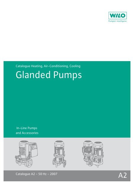
Catalogue Heating, Air-Conditioning, Cooling<br />
<strong>Glanded</strong> <strong>Pumps</strong><br />
In-Line <strong>Pumps</strong><br />
and Accessories<br />
Catalogue A2 - 50 Hz - 2007 A2
Program overview and fields of application<br />
<strong>Glanded</strong> pumps<br />
Pump type Main field of application<br />
Energy-saving <strong>Pumps</strong> 15<br />
Single-head pumps Wilo-VeroLine-IP-E • • • 16<br />
Wilo-CronoLine-IL-E • • • 16<br />
Wilo-CronoLine-IL-E...BF • • • 16<br />
Twin-head pumps Wilo-VeroTwin-DP-E • • • 16<br />
Wilo-CronoTwin-DL-E • • • 16<br />
Standard <strong>Pumps</strong> 67<br />
Single-head pumps Wilo-VeroLine-IPL • • • 68<br />
Wilo-CronoLine-IL • • • 68<br />
Twin-head pumps Wilo-VeroTwin-DPL • • • 68<br />
Wilo-CronoTwin-DL • • • 68<br />
Special <strong>Pumps</strong> 149<br />
Single-head pumps Wilo-VeroLine-IPS • • • 150<br />
Monobloc <strong>Pumps</strong><br />
Wilo-VeroLine-IPH-O / -W • • • 150<br />
Wilo-VeroLine-IP-Z • • • • 150<br />
Single-head pumps Wilo-BAC • •<br />
Wilo-CronoBloc-BL • • •<br />
Legend: Fields of application:<br />
• Applicable<br />
1) See Catalogue A3 – Monobloc and Norm <strong>Pumps</strong>, Axially Split<br />
Case <strong>Pumps</strong><br />
New in the program or series expansion or modification<br />
Heating Industrial applications<br />
Air-conditioning / cooling Potable water circulation<br />
1 Subject to change without prior notice 09/2006 Wilo AG<br />
Page<br />
1) )
Contents<br />
Wilo Catalogue A2 - <strong>Glanded</strong> pumps<br />
General Notes and Abbreviations 4<br />
Planning Guide 6<br />
Energy-saving pumps<br />
Contents 15<br />
Series overview 16<br />
Wilo-VeroLine-IP-E, CronoLine-IL-E, CronoLine-IL-E...BF,<br />
Wilo-VeroTwin-DP-E, CronoTwin-DL-E<br />
Standard pumps<br />
Contents 67<br />
Series overview 68<br />
Wilo-VeroLine-IPL, CronoLine-IL,<br />
Wilo-VeroTwin-DPL, CronoTwin-DL<br />
Special In-line <strong>Pumps</strong><br />
Contents 149<br />
Series overview 150<br />
Wilo-VeroLine-IPS, VeroLine-IPH-O / -W, VeroLine-IP-Z<br />
Switching and Control Devices<br />
Pump Management Systems Wilo-Control<br />
Contents Switching and Control Devices 167<br />
Series overview 168<br />
Switching and Control Devices<br />
Contents Pump Management Systems Wilo-Control 199<br />
Series overview 200<br />
Pump Management Systems Wilo-Control<br />
3<br />
Planning Guide<br />
Energy-saving pumps<br />
Standard pumps<br />
Special In-line <strong>Pumps</strong><br />
Switching and Control Devices<br />
Pump management
General Notes and Abbreviations<br />
Abbreviations and what they mean<br />
Abbreviation Meaning<br />
1~ 1-phase alternating current<br />
1/min revolutions per minute (rpm)<br />
3~ 3-phase current<br />
Autopilot Automatic adjustment of pump performance during<br />
setback phases, e.g. boiler setback operation<br />
overnight<br />
blsf Blocking current-proof, no motor protection<br />
DM 3-phase AC motor<br />
p-c Control mode for constant differential pressure<br />
p-T Control mode for differential-pressure control as<br />
a function of media temperature<br />
p-v Control mode for variable differential pressure<br />
T Control mode for differential temperature<br />
ECM<br />
technology<br />
Electronically commutated motor with new wet<br />
rotor encapsulation. Newly developed glandless<br />
drive concept for high-efficiency pumps.<br />
EnEV German energy-saving act<br />
(Energie-Einsparverordnung)<br />
EM 1-phase AC motor<br />
Ext. Off Control input “Overriding Off”<br />
Ext. Min Control input “Overriding Min”, e.g. for setback<br />
operation without autopilot<br />
GRD Residual-current device<br />
GTW Building automation<br />
°d Mechanical seal<br />
H Special cast iron: white malleable cast iron<br />
IF Degree of German water hardness, unit for assessing<br />
water hardness<br />
Inox Delivery head<br />
Int. MS Interface<br />
IR Stainless steel<br />
KDS Internal motor protection, pumps with internal<br />
protection against unacceptable high winding<br />
temperature<br />
KLF Infrared interface<br />
Cap capacitors<br />
TRS PTC thermistor sensor<br />
KTL coating Cataphoretic painting:<br />
Paintwork with high adhesive strength for longlasting<br />
corrosion protection<br />
Abbreviation Meaning<br />
KTW Authorisation for products with plastics, for utilisation<br />
in potable water applications<br />
LON Local operating network<br />
(open, non-manufacturer-dependent, standardised<br />
databus system in LONWORKS networks)<br />
MOT Motor module (drive motor + impeller + terminal<br />
box / electronic module) for exchange in the<br />
TOP-..-series<br />
PLR Pump master computer<br />
PT 100 Platinum temperature sensor with a resistance<br />
value of 100 at 0 °C<br />
Q (= V ) Delivery rate<br />
.<br />
SBM Run signal or collective run signal<br />
SSM Fault signal or collective fault signal<br />
Control input<br />
“0...10 V”<br />
Analogue input for external activation<br />
of functions<br />
TOP-Control Building automation management with pumps and<br />
accessories<br />
TrinkwV 2001 German potable water ordinance of 2001<br />
(valid from 01.01.2003)<br />
VDI 2035 VDI guideline for preventing damage in hot-water<br />
heating installations<br />
WSK Thermal winding contacts (in motor for monitoring<br />
winding temperature, full motor protection<br />
through additional tripping unit)<br />
WRAS Water Regulations Advisory Scheme<br />
Operating mode of twin-head pumps:<br />
Individual operation of the respective operating<br />
pump<br />
Operating mode of twin-head pumps:<br />
Parallel operation of both pumps<br />
No. of poles for the pumps: 2-pole<br />
No. of poles for the pumps: 4-pole<br />
No. of poles for the pumps: 6-pole<br />
4 Subject to change without prior notice 09/2006 WILO AG<br />
+
General Notes and Abbreviations<br />
Note<br />
According to the German energy-saving act EnEV, starting from<br />
1.2.2002, boilers with outputs in excess of 25 kW must be equipped<br />
with either switchgear-equipped heating pumps for automatic performance<br />
control or electronically controlled pumps.<br />
Pump replacement<br />
Please refer to the current Wilo heating pumps replacement guide for<br />
more detailed information.<br />
Wear and tear<br />
<strong>Pumps</strong> or parts of pumps are subject to wear in accordance with<br />
state-of-the-art technology (DIN 31051 / DIN-EN 13306). This wear<br />
may vary depending on operating parameters (temperature, pressure,<br />
water condition) and the installation / usage situation and may result<br />
in the malfunction or failure at different times of the above-mentioned<br />
products / components including their electrical / electronic<br />
circuitry.<br />
Wearing parts are all components subject to rotary or dynamic strain,<br />
including electronic components under tension, in particular:<br />
- seals / gaskets (including rotating mechanical seals), seal ring<br />
Wilo Catalogue A2 - <strong>Glanded</strong> pumps<br />
- bearings and shafts<br />
- stuffing boxes<br />
- capacitors<br />
- relays / contactors / switches<br />
- electronic circuits, semiconductor components, etc.<br />
-impellers<br />
- wearing rings / wearing plates<br />
We do not accept liability for faults or defects arising from natural<br />
wear and tear.<br />
WILO – General terms of delivery and service<br />
The latest version of our General Terms of Delivery and Service can be<br />
found on the Internet at<br />
www.wilo.com<br />
5<br />
Planning Guide<br />
Energy-saving pumps<br />
Standard pumps<br />
Special pumps<br />
Switching and Control Devices/<br />
Pump Management Systems
Planning Guide<br />
Note on range of application<br />
This Planning Guide applies to:<br />
- electronically controlled Inline pumps belonging to any of these<br />
series: IP-E, DP-E, IL-E, DL-E, IL-E .. BF<br />
- non-controlled In-line pumps belonging to any of these series:<br />
IPL, DPL, IL, DL, IPs, IPH-O / -W, IP-Z<br />
- Monobloc pumps of the BL Series<br />
Pump selection<br />
<strong>Glanded</strong> pumps are ideally suited for use in conjunction with larger<br />
plant systems covering a wide range of applications in the field of hot<br />
water / central heating and air conditioning / cooling. The technically<br />
correct selection of a pump involves a number of factors:<br />
- The correct pump size to achieve the required duty point<br />
- The correct pump design to satisfy the process parameters (e.g. pressure<br />
and temperature)<br />
- The right materials to satisfy endurance requirements.<br />
The overview duty charts in the program overview section of the<br />
catalogue allows you to roughly select the series of pump you need,<br />
helping you ultimately select the most suitable size of pump within<br />
the respective model series more quickly. Frequently, pumps of various<br />
model series are found to be hydraulically suitable in the edge<br />
region of the duty charts. Accurate selection of the required pump<br />
size is possible only with the aid of the individual pump curve. These<br />
are provided in this catalogue and within the Wilo planning software<br />
(available on CD-ROM and online at www.wilo-select.com).<br />
The Technical Data section of the catalogue provides information on<br />
the application limits with respect to pressure, temperature and<br />
material options. In addition, this section of the catalogue provides<br />
information on pump equipment.<br />
Pump curve<br />
An optimally dimensioned pump has its duty point in the region of<br />
maximum efficiency. At the duty point there is equilibrium between<br />
the power output of the pump (Figure 1, Curve P) and the power consumption<br />
required to overcome the resistance of the pipe system<br />
(Figure 1, Curve A1).<br />
Tolerances in accordance with ISO 9906, Appendix 1, are to be taken into<br />
account for all of the pump curves illustrated.<br />
Figure 1<br />
H<br />
[m]<br />
P 2<br />
[kW]<br />
Q min<br />
Q nenn<br />
A 1<br />
Q max<br />
Q[m 3 /h]<br />
P max<br />
Q[m 3 /h]<br />
A 2<br />
The point of highest efficiency is located approximately in the upper<br />
third of the pump curve, or is indicated on the performance diagram.<br />
The planning engineer must locate a dimensioned duty point to<br />
match the maximum requirements of the pump.<br />
In the case of a heating pump, this is the capacity to meet the calculated<br />
standard heating load of the building. All other duty points<br />
occurring in practice lie on the pump curve to the left of the duty<br />
point Q nenn. The pump thus operates in its highest efficiency range. If<br />
the actual resistance of the pipe system is lower than that on which<br />
the pump selection has been based, then the duty point may lie outside<br />
the pump curve (Figure 1, Curve A2). This may lead to an inadmissibly<br />
high power consumption and hence to an overload of the<br />
selected motor. In this case it is necessary to reassess the duty point<br />
and, if necessary, to use a more powerful pump. The minimum flow<br />
volume Q min of a glanded pump is 10 % of Q max (Figure 1).<br />
The incremental pump curves provided for pumps and, in particular,<br />
for power selection, are intended for use when there is reliable<br />
knowledge of the duty point. When reliable knowledge of the duty<br />
point is unavailable, our basic recommendation is to select the pump<br />
with the maximum electrical power capability.<br />
Cavitation<br />
Avoidance of cavitation is an important part of correct pump selection.<br />
This is particularly so in open systems (e. g. cooling tower systems)<br />
and at very high temperatures and low system pressures.<br />
The pressure drop in a flowing fluid, e.g. due to frictional resistance in<br />
the pipe, a change in absolute velocity or the geodetic head, leads to<br />
the local formation of vapour bubbles, when the static pressure<br />
reduces to the vapour pressure of the fluid (Fig. 2).<br />
The vapour bubbles are carried along by the flow, collapsing suddenly<br />
if the static pressure increases again above the vapour pressure<br />
(Fig. 3).<br />
Negative pressure Positive pressure<br />
Figure 2 Figure 3<br />
This process is called cavitation. The collapse of the vapour bubbles<br />
causes micro-jets which, on hitting the surface of a wall, cause<br />
destruction of the wall material in the form of pitting.<br />
To avoid cavitation, special attention must therefore be given to the<br />
maintenance of the correct pressure.<br />
If the available intake pressure (or static pressure) in the pipe system<br />
is not high enough to meet the static head required for the pump<br />
(maintained pressure head or NPSH), appropriate measures will be<br />
required to increase the static head to at least achieve equilibrium. This<br />
can be implemented by:<br />
- Increasing the static pressure (pump positioning).<br />
- Reducing the fluid temperature (reduced vapour pressure pD)<br />
- Selecting a pump with a lower maintained pressure head (NPSH) (as<br />
arule a larger size pump)<br />
6 Subject to change without prior notice 09/2006 WILO AG
Planning Guide<br />
Maintained pressure head NPSH<br />
The maintained pressure head (NPSH) is pump-specific and is displayed<br />
in the performance diagram for the pump (Fig.4). The NPSH<br />
values are based on the respective maximum impeller size. In order to<br />
allow for any uncertainty in the specification of the duty point, when<br />
selecting the pump the values should be increased by a safety factor<br />
of 0.5 m.<br />
Fig. 4<br />
H<br />
[m]<br />
Wilo Catalogue A2 - <strong>Glanded</strong> pumps<br />
NPSH<br />
Q[m 3 /h]<br />
Series<br />
A hydraulically suitable pump must, in addition, satisfy the required<br />
operating conditions. To do so it is necessary to consider the maximum<br />
permissible operating temperature and pressure.<br />
Construction<br />
In-line pumps<br />
Wilo In-line pumps are single-stage, low-pressure centrifugal pumps<br />
incorporating the In-line method of construction with inlet and outlet<br />
ports of the same nominal diameter and with air-cooled IEC<br />
standard motors. Flange PN 16 with pressure measuring connection<br />
R 1/ 8 . The pump housing is provided with feet as standard.<br />
Monobloc pumps<br />
Wilo Monobloc pumps are single-stage, low-pressure centrifugal<br />
pumps in monobloc construction in accordance with EN 733 with aircooled<br />
IEC standard motors. Cast iron volute casing with axial inlet<br />
port and radial delivery port, flange PN 16 with pressure-measuring<br />
connection R 1/ 8 . The pumps are equipped, as standard, with angled<br />
or motor feet.<br />
7<br />
Planning Guide<br />
Energy-saving pumps<br />
Standard pumps<br />
Special pumps<br />
Pump management
Planning Guide<br />
Materials<br />
The selection of materials for all parts in contact with the fluid is of<br />
importance to the chemical resistance of the pump.<br />
Materials<br />
Fluids Application limits<br />
(The maximum permissible<br />
operating temperatures<br />
and pressures of<br />
the pump series must be<br />
adhered to)<br />
Materials housing<br />
/ impeller<br />
Heating water<br />
(in accordance with VDI 2035)<br />
(Conductivity
Planning Guide<br />
Mechanical seal<br />
A mechanical seal is fitted as standard on all Wilo glanded pumps<br />
(Except IPs) (Fig. 5). Mechanical seals are dynamic seals and are used<br />
to seal rotating shafts at medium to high working pressures. The<br />
dynamic sealing area of the mechanical seal comprises two surfaceground,<br />
wear-resistant faces (e.g. silicon carbide or carbon rings),<br />
which are held together by axial forces. The slip ring rotates with the<br />
shaft, whilst the mating ring remains stationary in the housing. The<br />
required axial force to maintain contact between the rings is exerted<br />
by a spring and the fluid pressure.<br />
Fig. 5<br />
As a rule, during operation there is little or no drip leakage, and no<br />
maintenance work is necessary. The average life, when subjected to<br />
average operating and water conditions, is between 2 and 4 years,<br />
but extreme conditions (soiling, additives and overheating) may<br />
drastically reduce the life.<br />
Important:<br />
Mechanical seals are subject to wear and tear. Dry-running is not permissible<br />
as it will lead to the destruction of the sealing faces.<br />
The mechanical seal fitted as standard by Wilo can be used for waterglycol<br />
mixtures with 20 – 40 Vol.-% glycol and a medium temperature<br />
of 40 °C.<br />
Outside the limits of these parameters silicate precipitation can take<br />
place which may damage the standard seals. Non-standard mechanical<br />
seals are available on request for use outside these limitations.<br />
When additives such as glycol are used or oil polluted water is<br />
encountered, then in addition to the suitability of the mechanical<br />
seal, it may be necessary to check the performance of the pump (in<br />
the case of glycol additions from 20 % by volume).<br />
The power requirement P 2 of a pump can be calculated from the following<br />
formula:<br />
P 2 = Power requirement [kW]<br />
= Density [kg/dm 3 ]<br />
Q = Flow volume [m 3 /h]<br />
H = Delivery head [m]<br />
= Pump efficiency (e.g. 0.8 at 80 %)<br />
Mechanical seals – material identification code<br />
The materials of a mechanical seal are identified by means of a 5-part<br />
code. The “Technical data” tables for the glanded pumps contain the<br />
code for each series. The code characters relate to the following seal<br />
components:<br />
Wilo Catalogue A2 - <strong>Glanded</strong> pumps<br />
QH P<br />
2<br />
=<br />
-----------------------<br />
367 <br />
1: Seal face<br />
2: Mating ring<br />
3: Secondary seals<br />
4: Spring<br />
5: Other components<br />
Typical materials:<br />
1: A Carbon-graphite (antimony-impregnated)<br />
B Carbon-graphite (artificial resin-impregnated), approved for<br />
use with food<br />
Q1 Silicone carbide<br />
2: Q1 Silicon carbide<br />
3: E EPDM<br />
E3 EPDM, approved for use with food<br />
V Viton<br />
X4 HNBR<br />
4: G Stainless steel<br />
5: G Stainless steel<br />
The standard seal on Wilo glanded pumps is AQ1EGG.<br />
Cataphoretic painting<br />
Wilo glanded pumps are provided as standard with a cataphoresis<br />
coating (Exceptions: Series IL 250, IPS, IPH-O, IPH-W, IP-Z). External<br />
components which are susceptible to corrosion such as hexagon<br />
head bolts, couplings etc., are chromated. The advantages of these<br />
coatings lie in their resistance to corrosion caused by aggressive<br />
atmospheres, such as humid air, condensation and an environment<br />
containing salt and chemicals. <strong>Pumps</strong> with cast components with<br />
a cataphoresis coating and chromated components, to combat rust,<br />
are suitable for heating and air conditioning / cooling applications in<br />
both internal and outside use (a special motor is required for outside<br />
applications). These pumps also offer the advantage of low maintenance<br />
costs and longer life.<br />
Heat insulation of pumps<br />
In systems, which are heat-insulated, only the pump housing should<br />
be insulated, not the lantern or the motor.<br />
Location / positioning of pumps<br />
The standard pumps must be protected from the weather and<br />
installed in a frost / dust-free, well-ventilated and non-explosive<br />
atmosphere. Pipelines and pumps should be installed in a stress-free<br />
condition. The pipelines must be fixed in such a way that the pump is<br />
not supporting the weight of the pipeline.<br />
In-line pumps are designed for direct horizontal and vertical installation<br />
in a pipeline. Installation with the motor and the terminal box<br />
facing downwards is not permissible. Sufficient clearance must be<br />
provided for the removal of motor, lantern and impeller. From a motor<br />
power of 18.5 kW it is not permissible to install the pump with the<br />
pump shaft in a horizontal attitude. On a vertically mounted pump<br />
the pipeline must be stress-free and the pump must be supported on<br />
the pump feet.<br />
The installation of monobloc pumps with the motor and terminal box<br />
facing downwards is not permissible. All other installed attitudes are<br />
possible. Monobloc pumps are to be mounted on concrete foundations<br />
or support brackets.<br />
9<br />
Planning Guide<br />
Energy-saving pumps<br />
Standard pumps<br />
Special pumps<br />
Pump management
Planning Guide<br />
Anticipated noise levels for In-line and monobloc pumps<br />
(Orientation values)<br />
Motor power<br />
P N [kW]<br />
Sound-pressure level pA (dB) 1)<br />
Pump with motor<br />
1450 rpm 2900 rpm<br />
< 0.55 52 55<br />
000.75 53 58<br />
001.1 54 58<br />
001.5 54 61<br />
002.2 57 62<br />
003.0 58 64<br />
004.0 58 67<br />
005.5 63 70<br />
007.5 64 71<br />
011.0 67 74<br />
015.0 68 75<br />
018.5 67 76<br />
022.0 67 77<br />
030.0 69 78<br />
037.0 68 74<br />
045.0 68 74<br />
055.0 68 78<br />
075.0 70 80<br />
090.0 70 80<br />
110.0 72 82<br />
132.0 72 82<br />
160.0 72 82<br />
1) Spatial mean value of sound pressure level on a square plate a distance of<br />
1 m from the surface of the motor<br />
Electrical pump drives<br />
The rated power data and operating values for the electrical drives<br />
presented in this catalogue for glanded pumps (Inline and monobloc)<br />
apply at a rated frequency of 50 Hz, a rated voltage of 230 / 400 V to<br />
3 kW or 400 / 690 V starting at 4 kW, a maximum coolant temperature<br />
(KT) of 40°C and an installation altitude of up to 1000 m above<br />
mean sea level.<br />
For cases outside of these parameters a power rating reduction must<br />
be applied or a larger motor or a higher insulation class must be<br />
selected.<br />
All Wilo glanded pumps are fitted as standard with electric motors,<br />
which satisfy the IEC standard in terms of power and design. A<br />
restriction only applies where, due to the design of the pump, coupling<br />
to a standard motor is not possible. In this case motors with an<br />
extended shaft are used.<br />
The customary motor speed categories / operating speeds are as follows:<br />
No. of poles 50 Hz 60 Hz<br />
2 2900 rpm 3500 rpm<br />
4 1450 rpm 1750 rpm<br />
6 960 rpm 1150 rpm<br />
High-efficiency motor<br />
From a motor power of 1.1 kW Wilo glanded pumps can be supplied<br />
to order with EFF1 high efficiency motors.<br />
Application of explosion-protected pumps to directive<br />
94/9/EG (ATEX100a)<br />
Areas made hazardous by the risk of explosion are those, in which an<br />
explosion-supporting atmosphere (gas / dust) can occur in sufficient<br />
measure to present a risk.<br />
These areas are divided into zones. Decisions on the assignment of<br />
zones lie with the operator and the respective regulation authority.<br />
The testing of pumps (machines) and hence the approval for use in<br />
hazardous areas is governed in the EU on the basis of the relevant<br />
explosion protection specification 94 / 9 / EG (ATEX100a) by appropriate<br />
authorised test organisations. Approval is granted by means of<br />
a prototype test certificate. Wilo glanded pumps of Series IL, DL, BL,<br />
IPL (only variant –N), DPL (only variant -N), IPS and IPH can be supplied<br />
with the appropriate approvals for use in potentially explosive<br />
areas.<br />
These pumps have a prototype test certificate in accordance with<br />
directive 94 / 9 / EG (ATEX100a), which permits the following designations<br />
to be applied:<br />
II 2 G c b II A T3, T4 / II 2 G c b II C T3, T4<br />
CE = CE Symbol<br />
II = Equipment group<br />
G = Ex-Atmospheres due to gases, vapours and mist<br />
c = Design safety (Protection due to safe construction)<br />
b = Ignition source monitoring with T4<br />
T1-T4 = Temperature Class with maximum surface temperature<br />
T1 = 450°C<br />
T2 = 300°C<br />
T3 = 200°C<br />
T4 = 135°C<br />
e / d = Ignition protection category of the motor<br />
e = increased safety<br />
d = pressure-resistant enclosure<br />
Particular attention must be paid to ensure that for applications in<br />
the temperature range T4 the pumps and mechanical seals are additionally<br />
protected against dry running.<br />
10 Subject to change without prior notice 09/2006 WILO AG
Planning Guide<br />
This can take the form, for example, of monitoring the differential<br />
pressure or the motor nominal power.<br />
The motors have their own specific designations, e.g. EEXell T3<br />
- which stands for:<br />
E = Motor in accordance with European standards<br />
Ex = Explosion protection<br />
e = ignition protection category “Increased safety”<br />
II = Motor for potentially explosive areas<br />
T3 = Temperature Class<br />
Matrix of permissible operating conditions<br />
Fluid II A Mechanical<br />
seal<br />
The application of solvents is not permissible, since these may attack<br />
the elastomers in the seals. In turn, this can lead to uncontrolled leakage!<br />
Wilo Catalogue A2 - <strong>Glanded</strong> pumps<br />
Number of<br />
motor poles<br />
and must likewise be approved in accordance with the directive<br />
94/9/EG (ATEX100a).<br />
The approved operating conditions are illustrated in the following<br />
matrix:<br />
Note:<br />
Attention must also be paid in each application to the special features<br />
relating to the dependency on temperature, pressure, fluid<br />
medium and mechanical seal. The pumps must only be used for the<br />
permissible media listed in the following matrix (II B). However, outside<br />
the pump, the presence of gases satisfying the EX groups and<br />
temperature classifications is permitted (II C).<br />
IL / DL / BL IPL / DPL<br />
maximum permissible fluid temperature maximum permissible<br />
fluid temperature<br />
T4 1) T3 T4 1) T3<br />
P = 10 bar P = 16 bar P = 10 bar P = 16 bar P = 10 bar P = 10 bar<br />
Heating water in accordance with<br />
VDI 2035<br />
Standard<br />
2-pole<br />
4-pole<br />
100 °C<br />
115 °C<br />
90 °C<br />
110 °C<br />
140 °C<br />
140 °C<br />
120 °C<br />
120 °C<br />
120 °C<br />
120 °C<br />
120 °C<br />
120 °C<br />
Dealcalised water with:<br />
2-pole 100 °C 90 °C 140 °C 120 °C 120 °C 120 °C<br />
Conductivity > 80 µs,<br />
Silicates < 10 mg / l,<br />
pH value > 9<br />
Standard<br />
4-pole 115 °C 110 °C 140 °C 120 °C 120 °C 120 °C<br />
Mineral oil S2<br />
2-pole<br />
4-pole<br />
75 °C<br />
95 °C<br />
50 °C<br />
80 °C<br />
140 °C<br />
140 °C<br />
115 °C<br />
120 °C<br />
105 °C<br />
115 °C<br />
120 °C<br />
120 °C<br />
Heating water with: Conductivity<br />
2-pole 100 °C 90 °C 120 °C 120 °C 120 °C 120 °C<br />
< 850 µs, Silicates < 10 mg / l,<br />
Solid matter content < 10 mg / l<br />
Standard<br />
4-pole 115 °C 110 °C 120 °C 120 °C 120 °C 120 °C<br />
Condensate Standard<br />
2-pole<br />
4-pole<br />
100 °C<br />
100 °C<br />
90 °C<br />
100 °C<br />
100 °C<br />
100 °C<br />
100 °C<br />
100 °C<br />
100 °C<br />
100 °C<br />
100 °C<br />
100 °C<br />
Cooling brine, inorganic;<br />
pH value > 7.5, inhibited<br />
Standard 20 °C 20 °C 20 °C 20 °C 20 °C 20 °C<br />
Water with oil contamination<br />
Cooling water with frost protec-<br />
S2 90 °C 90 °C 90 °C 90 °C 90 °C 90 °C<br />
tion (pH value: 7.5-10; no galvanised<br />
components)<br />
Standard 40 °C 40 °C 40 °C 40 °C 40 °C 40 °C<br />
Water-glycol mixture<br />
(20 % – 40 % glycol)<br />
Standard 40 °C 40 °C 40 °C 40 °C 40 °C 40 °C<br />
1) <strong>Pumps</strong> and mechanical seals must be additionally protected against dry running in the temperature range T4.<br />
This can be achieved by monitoring the differential pressure or the nominal power of the motor.<br />
11<br />
Planning Guide<br />
Energy-saving pumps<br />
Standard pumps<br />
Special pumps<br />
Pump management
Planning Guide<br />
Scope of delivery<br />
Pump, including packing, installation and operating instructions<br />
Accessories<br />
Electronically controlled In-line pumps:<br />
- IF Modul: PLR or LON for the Series IP-E, DP-E, IL-E, DL-E (see also<br />
Catalogue section “Switching Devices and Control Systems”).<br />
- IR-Monitor for the Series IP-E, DP-E, IL-E, DL-E.<br />
- Analogue interface converter<br />
(see also Catalogue section “Switching Devices and Control Systems”)<br />
- Digital interface converter<br />
(see also Catalogue section “Switching Devices and Control Systems”).<br />
- Mounting brackets for installation on a base<br />
- Blank flanges for twin-head pumps<br />
Uncontrolled In-line and monobloc pumps:<br />
- Wilo control system for continuous regulation of motor speed to provide<br />
specified pump operating mode.<br />
- Changeover switches for automatic control of operational and<br />
reserve pumps (see also Catalogue section “Switching Devices and Control<br />
Systems”).<br />
- Mounting brackets for installation on a base<br />
- Blank flanges for twin-head pumps<br />
Pump duty splitting<br />
In association with the continuous regulation of power, the “Split<br />
solution” is available for optimisation, starting with the medium<br />
pump power range (1–1.5 kW). This provides for the use of 2 smaller<br />
pump aggregates or a twin-head pump in place of a large pump to<br />
distribute the maximum design performance.<br />
In the normal case, i.e. over 85% of the heating season, one pump is<br />
adequate as the basic load aggregate. The second pump is available<br />
to satisfy peak load requirements.<br />
Note:<br />
The extra cost of the pumps is more than compensated by power<br />
savings on the control devices.<br />
Advantages of pump duty splitting:<br />
- Electricity savings of between 50% and 70%<br />
- A second pump is always available for standby duty.<br />
With the so-called “Split solutions” one pump is operated for basic<br />
load requirements, whilst the other pumps are in parallel circuit for<br />
peak load duty.<br />
This ensures that the design requirement is in accordance with<br />
DIN 4701. In conjunction with an auto pump control system, continuous<br />
adjustment of pump capacity to the ever-changing load demand<br />
can be achieved.<br />
Note:<br />
Wilo Auto control systems for dual or multiple pump installations<br />
feature the peak-load operation facility.<br />
Continuously controlled peak load operation of a twin-head pump<br />
with two equal power motor impeller units.<br />
Caption:<br />
PH = Main pump (base load)<br />
PS = Trailing pump (peak load)<br />
QV = Full-load flow volume<br />
QT = Partial-load flow volume<br />
P1V = Full-load power consumption<br />
P1T = Partial-load power consumption<br />
Investment costs<br />
The total investment costs in heating systems can be reduced by<br />
almost 1 / 4 with “Split-solutions”. Particularly when use is made of<br />
twin-head pumps in place of single pumps, with their very high<br />
installation costs (Y-pipes, etc.)<br />
Note:<br />
Due to their low outlet velocities, Wilo twin-head pumps are particularly<br />
suitable for parallel operation.<br />
Operating costs<br />
Considerable reductions in the operating costs also ensue as a result<br />
of the large saving in current of the lower performance “Split aggregates”,<br />
since these supports better utilisation in the partial load range<br />
and, in particular, in the low load range.<br />
Standby facility<br />
From an operating point of view there are other advantages, because<br />
in the event of failure in the partial load range and the low load range<br />
a 100 % reserve is available and in the peak load range, on the few<br />
extremely cold days, there is a so-called emergency reserve (75%).<br />
12 Subject to change without prior notice 09/2006 WILO AG<br />
Delivery head H[%]<br />
Power requirement P[%]<br />
100<br />
40<br />
0<br />
100<br />
50<br />
0<br />
n = 60 %<br />
n = 2 x 100 %<br />
n = 100 %<br />
PH<br />
QT 50 % QV 100 %<br />
P1T<br />
Q[%]<br />
PH +<br />
PS<br />
p = constant<br />
P1V
Planning Guide<br />
Principle of operation<br />
Auto speed control applies to the main (base-load) pump head.<br />
With full stabilisation of this aggregate, i.e. with the nominal pump<br />
speed achieved and the start of the peak load requirement, the peak<br />
load aggregate switches in at a fixed speed (nominal speed), whilst<br />
the power of the controlled base load pump is directly reduced and<br />
adjusted to the load point. Pressure surges resulting from starting<br />
and stopping the trailing pumps are relatively minor and in practice<br />
have no appreciable effect. In parallel operation the constant speed<br />
peak load aggregate and the controllable base load aggregate are<br />
added, based on delivery flow, which in this operating situation readjusts<br />
for the respective peak load requirement.<br />
The switch-point for adding the peak-load head is determined by means<br />
of a unit-integrated electronic assessment logic.<br />
Note:<br />
Peak-load control functions of Wilo auto control systems are only<br />
possible on head- or differential temperature-sensitive control<br />
modes.<br />
Further information on pump regulation is contained in the catalogue<br />
section “Switching devices and control systems”.<br />
Twin-head pump switching<br />
There are two operating modes for the operation of twin-head<br />
pumps:<br />
- Standby switching of one pump with the other is on duty in singlepump<br />
operation.<br />
- Peak load switching with parallel operation of both pumps, which are<br />
also combined from a control option on the respective operating<br />
pump.<br />
Operating modes<br />
Standby operation Peak load operation<br />
No. I or No. II pump in operation Both pumps operating<br />
Duty pump uncontrolled<br />
Pump I<br />
Investment costs:<br />
Operating costs:<br />
Wilo Catalogue A2 - <strong>Glanded</strong> pumps<br />
Pump II<br />
lower<br />
high<br />
Pump I + II<br />
higher<br />
low<br />
Operating pump controlled by means of Wilo control system<br />
Pump I<br />
Investment costs<br />
(Including control):<br />
Operating costs:<br />
Pump II<br />
higher<br />
higher<br />
Pump I + II<br />
lower<br />
low<br />
Operating Functions<br />
Wilo switching devices feature the following operating functions:<br />
A standby switching, fault-sensitive or time-sensitive operational<br />
changeover Pump I Pump II.<br />
B Peak-load operation for load- or time-sensitive automatic load<br />
adjustment through ON / OFF control of the trailing pump.<br />
C Infinitely-variable speed control of the leading pump for load- or<br />
time-sensitive automatic power adjustment when the trailing<br />
pump it switched on for infinitely-variable peak-load service.<br />
Switchgear Switch function<br />
A B C<br />
SD Series (Standby / Cut-in) • • –<br />
S2R 3D (Standby / Cut-in) • • –<br />
CR System (stepless) • • •<br />
Series S2R 3D / SD<br />
Changeover panels for auto-control of operating and standby pumps<br />
of dual sets. Automatic fault-actuated changeover from operating to<br />
standby pump. Automatic time-controlled routine duty changeover<br />
of operating and standby pumps.<br />
Additional peak load switching through series standard connection<br />
option for the 2nd pump.<br />
Short-term parallel running is integrated into the changeover<br />
sequence to avoid the occurrence of valve noise during uncontrolled<br />
changeover.<br />
Version in ISO housing, Protection Class: IP 41. Potential-free contact<br />
for collective fault signal.<br />
Connection options to three-phase current 400 V, 50 Hz, or threephase<br />
230 V, 50 Hz.<br />
Non-standard voltages and frequencies on request.<br />
Technical Data<br />
Switchgear type Motor power<br />
[kW]<br />
S2R 3D 0.37-3<br />
SD 5.5 4-5.5<br />
SD 9 7.5- 9<br />
SD 18.5 11-18.5<br />
SD 30 22-30<br />
SD 37 37<br />
13<br />
Planning Guide<br />
Energy-saving pumps<br />
Standard pumps<br />
Special pumps<br />
Pump management
Planning Guide<br />
14 Subject to change without prior notice 09/2006 WILO AG
Energy-Saving <strong>Pumps</strong><br />
Contents<br />
Energy-saving pumps<br />
Wilo Catalogue A2 - <strong>Glanded</strong> pumps<br />
Series overview 16<br />
Single-head pumps In-line Wilo-VeroLine-IP-E<br />
(Heating, Air-conditioning, Cooling and Industry) Equipment / Function 20<br />
Technical Data 20<br />
Pump Curves 24<br />
Terminal Diagrams, Motor Data 33<br />
Dimensions, Weights 34<br />
Wilo-CronoLine-IL-E<br />
Equipment / Function 20<br />
Technical Data 20<br />
Pump Curves 36<br />
Terminal Diagrams, Motor Data 36<br />
Dimensions, Weights 39<br />
Wilo-CronoLine-IL-E...BF<br />
Equipment / Function 20<br />
Technical Data 20<br />
Pump Curves 40<br />
Terminal Diagrams, Motor Data 40<br />
Dimensions, Weights 40<br />
Twin-head pumps In-line Wilo-VeroTwin-DP-E<br />
(Heating, Air-conditioning, Cooling and Industry) Equipment / Function 20<br />
Technical Data 20<br />
Pump Curves 59<br />
Terminal Diagrams, Motor Data 59<br />
Dimensions, Weights 59<br />
Wilo-CronoTwin-DL-E<br />
Equipment / Function 20<br />
Technical Data 20<br />
Pump Curves 61<br />
Terminal Diagrams, Motor Data 61<br />
Dimensions, Weights 66<br />
15<br />
Planning Guide<br />
Energy-saving pumps<br />
Standard pumps<br />
Special pumps<br />
Switching and Control Devices/<br />
Pump Management Systems
Energy-Saving <strong>Pumps</strong><br />
Single-head pumps In-line (Heating, Air-conditioning, Cooling and Industry)<br />
Series overview<br />
Series: Wilo-VeroLine-IP-E<br />
Series expansion<br />
Series: Wilo-CronoLine-IL-E<br />
Series: Wilo-CronoLine-IL-E...BF<br />
H[m]<br />
25<br />
20<br />
15<br />
10<br />
5<br />
0<br />
0<br />
H[m]<br />
10<br />
IP-E 32<br />
IP-E 40<br />
IP-E 50<br />
IP-E 65<br />
IP-E 80<br />
20<br />
IL-E 40/9-39<br />
30<br />
40<br />
Wilo-VeroLine-IP-E<br />
50 60 70 80 90 Q[m³/h]<br />
Wilo-CronoLine-IL-E<br />
IL-E 50/10-36 IL-E 80/5-22<br />
35<br />
30<br />
25<br />
20<br />
15<br />
10<br />
5<br />
0<br />
0 20 40 60 80 100 120<br />
H[m]<br />
60<br />
50<br />
40<br />
30<br />
IL-E 65 BF<br />
IL-E 65/6-24<br />
>Single-head pumps:<br />
• Electronically controlled In-line pumps with<br />
flange connection<br />
>Application:<br />
• For pumping cold and hot water (in accordance<br />
with VDI 2035) without abrasive substances<br />
in heating, cold water and cooling<br />
water systems<br />
>Special features:<br />
• Simple operation with infrared interface (IR-<br />
Monitoring)<br />
• Optional interfaces via retrofit IF-Modules for<br />
bus communication, LON or PLR<br />
• Integrated dual pump management<br />
>Single-head pumps:<br />
• Electronically controlled In-line pumps with<br />
flange connection<br />
> Application:<br />
• For pumping cold and hot water (in accordance<br />
with VDI 2035) without abrasive substances<br />
in heating, cold water and cooling<br />
water systems<br />
> Special features:<br />
• Simple operation with infrared interface<br />
(IR-Monitoring)<br />
• Optional interfaces via retrofit IF-Modules for<br />
bus communication, LON or PLR<br />
• Retrofit twin-head pump management system<br />
>Single-head pumps:<br />
• Electronically controlled In-line pumps with<br />
flange connection<br />
>Application:<br />
• For pumping cold and hot water (in accordance<br />
with VDI 2035) without abrasive substances<br />
in heating, cold water and cooling<br />
water systems<br />
>Special features:<br />
• Powerful, up to 22 kW<br />
16 Subject to change without prior notice 09/2006 WILO AG<br />
IL-E 80 BF<br />
Q[m 3 /h]<br />
Wilo-CronoLine-IL-E...BF<br />
20<br />
10<br />
0<br />
10 20 30 40 50 60 80 100 150 200 Q[m3 /h]<br />
IL-E 100 BF
Energy-Saving <strong>Pumps</strong><br />
Single-head pumps In-line (Heating, Air-conditioning, Cooling and Industry)<br />
Series overview<br />
Series: Wilo-VeroLine-IP-E<br />
>Product advantages:<br />
• Energy saving due to integrated electronic<br />
performance control<br />
• Standard interfaces for connection with<br />
building automation systems<br />
• Display of volumetric flow tendencies<br />
• High corrosion protection thanks to cataphoretic<br />
painting<br />
• Mechanical seals with forced flushing independent<br />
of direction of rotation<br />
• Easy to install. The pump housing is provided<br />
with feet and a threaded bores<br />
Series: Wilo-CronoLine-IL-E<br />
> Product advantages:<br />
• Energy saving due to integrated electronic<br />
performance control<br />
• Available for flexible applications in air conditioning<br />
and cooling systems benefiting<br />
from targeted draining of condensate via<br />
optimised lantern design<br />
• High corrosion protection thanks to cataphoretic<br />
painting<br />
• High motor life due to the production<br />
standard condensate outlet holes in the<br />
motor housings<br />
• Simple operation with infrared interface<br />
(IR-Monitoring)<br />
Series: Wilo-CronoLine-IL-E...BF<br />
> Product advantages:<br />
• Powerful, up to 22 kW<br />
• High corrosion protection thanks to cataphoretic<br />
painting<br />
• Mechanical seals with forced flushing independent<br />
of direction of rotation<br />
• Easy to install. The pump housing is provided<br />
with feet and a threaded bores<br />
Wilo Catalogue A2 - <strong>Glanded</strong> pumps<br />
• Optimised interfaces via retrofit IF-Modules<br />
for bus communication, LON or PLR for bus<br />
communication<br />
• Mechanical seals with forced flushing independent<br />
of direction of rotation<br />
• Easy to install. The pump housing is provided<br />
with feet and a threaded bores<br />
• Reduced Life Cycle Costs through optimised<br />
degrees of efficiency<br />
>Additional information: Page<br />
• Planning Guide . . . . . . . . . . . . . . . . . . . 6<br />
• Equipment / Function. . . . . . . . . . . . . 20<br />
• Technical Data . . . . . . . . . . . . . . . . . . . 22<br />
• Pump Curves. . . . . . . . . . . . . . . . . . . . . 24<br />
• Terminal Diagrams, Motor Data . . . . 33<br />
• Dimensions, Weights . . . . . . . . . . . . . 34<br />
• Switching and Control Devices. . . . . 167<br />
• Pump Management Systems<br />
Wilo-Control . . . . . . . . . . . . . . . . . . . . 200<br />
>Additional information: Page<br />
• Planning Guide . . . . . . . . . . . . . . . . . . . 6<br />
• Equipment / Function. . . . . . . . . . . . . 20<br />
• Technical Data . . . . . . . . . . . . . . . . . . . 22<br />
• Pump Curves. . . . . . . . . . . . . . . . . . . . . 36<br />
• Terminal Diagrams, Motor Data . . . . 36<br />
• Dimensions, Weights . . . . . . . . . . . . . 39<br />
• Switching and Control Devices. . . . . 167<br />
• Pump Management Systems<br />
Wilo-Control . . . . . . . . . . . . . . . . . . . . 200<br />
>Additional information: Page<br />
• Planning Guide . . . . . . . . . . . . . . . . . . . 6<br />
• Equipment / Function. . . . . . . . . . . . . 20<br />
• Technical Data . . . . . . . . . . . . . . . . . . . 22<br />
• Pump Curves. . . . . . . . . . . . . . . . . . . . . 40<br />
• Terminal Diagrams, Motor Data . . . . 43<br />
• Dimensions, Weights . . . . . . . . . . . . . 44<br />
• Switching and Control Devices. . . . . 167<br />
17<br />
Planning Guide<br />
Energy-saving pumps<br />
Standard pumps<br />
Special pumps<br />
Switching and Control Devices/<br />
Pump Management Systems
Energy-Saving <strong>Pumps</strong><br />
Twin-head pumps In-line (Heating, Air-conditioning, Cooling and Industry)<br />
Series overview<br />
Series: Wilo-VeroTwin-DP-E<br />
Series: Wilo-CronoTwin-DL-E<br />
H[m]<br />
25<br />
20<br />
15<br />
10<br />
5<br />
0<br />
0<br />
H[m]<br />
DP-E 32<br />
DP-E 40<br />
DP-E 50<br />
DP-E 65<br />
DP-E 80<br />
10<br />
20<br />
DL-E 40/9-39<br />
30<br />
40<br />
Wilo-VeroTwin-DP-E<br />
50 60 70 80 90 Q[m³/h]<br />
35<br />
30<br />
25<br />
20<br />
15<br />
10<br />
5<br />
0<br />
0 20 40 60 80 100 120<br />
DL-E 65/6-24<br />
DL-E 50/10-36<br />
Wilo-CronoTwin-DL-E<br />
DL-E 80/5-22<br />
> Twin-head pumps:<br />
• Electronically controlled In-line pumps with<br />
flange connection<br />
>Application:<br />
• For pumping cold and hot water (in accordance<br />
with VDI 2035) without abrasive substances<br />
in heating, cold water and cooling<br />
water systems<br />
> Special features:<br />
• Simple operation with infrared interface<br />
(IR-Monitoring)<br />
• Optional interfaces via retrofit IF-Modules<br />
for bus communication, LON or PLR<br />
• Integrated dual pump management<br />
18 Subject to change without prior notice 09/2006 WILO AG<br />
Q[m 3 /h]
Energy-Saving <strong>Pumps</strong><br />
Twin-head pumps In-line (Heating, Air-conditioning, Cooling and Industry)<br />
Series overview<br />
Series: Wilo-VeroTwin-DP-E<br />
>Product advantages:<br />
• Energy saving due to integrated electronic<br />
performance control<br />
• High corrosion protection thanks to cataphoretic<br />
painting<br />
• Mechanical seals with forced flushing independent<br />
of direction of rotation<br />
• Easy to install. The pump housing is provided<br />
with feet and a threaded bores.<br />
Series: Wilo-CronoTwin-DL-E<br />
> Product advantages:<br />
• Energy saving due to integrated electronic<br />
performance control<br />
• High corrosion protection thanks to cataphoretic<br />
painting<br />
• Mechanical seals with forced flushing independent<br />
of direction of rotation<br />
• Easy to install. The pump housing is provided<br />
with feet and a threaded bores.<br />
Wilo Catalogue A2 - <strong>Glanded</strong> pumps<br />
>Additional information: Page<br />
• Planning Guide . . . . . . . . . . . . . . . . . . . 6<br />
• Equipment / Function. . . . . . . . . . . . . 20<br />
• Technical Data . . . . . . . . . . . . . . . . . . . 22<br />
• Pump Curves. . . . . . . . . . . . . . . . . . . . . 59<br />
• Terminal Diagrams, Motor Data . . . . 58<br />
• Dimensions, Weights . . . . . . . . . . . . . 59<br />
• Switching and Control Devices. . . . . 167<br />
• Wilo-TOP-Control Pump<br />
Management Systems . . . . . . . . . . . . 200<br />
>Additional information: Page<br />
• Planning Guide . . . . . . . . . . . . . . . . . . . 6<br />
• Equipment / Function. . . . . . . . . . . . . 20<br />
• Technical Data . . . . . . . . . . . . . . . . . . . 22<br />
• Pump Curves. . . . . . . . . . . . . . . . . . . . . 61<br />
• Terminal Diagrams, Motor Data . . . . 65<br />
• Dimensions, Weights . . . . . . . . . . . . . 66<br />
• Switching and Control Devices. . . . . 167<br />
• Wilo-TOP-Control Pump<br />
Management Systems . . . . . . . . . . . . 200<br />
19<br />
Planning Guide<br />
Energy-saving pumps<br />
Standard pumps<br />
Special pumps<br />
Switching and Control Devices/<br />
Pump Management Systems
Energy-Saving <strong>Pumps</strong><br />
Single-head pumps In-line, double pumps In-line<br />
Equipment / Function<br />
Operating modes<br />
Wilo-<br />
VeroLine-<br />
IP-E<br />
Wilo-<br />
CronoLine-<br />
IL-E<br />
Wilo-<br />
CronoLine-<br />
IL-E..BF<br />
Wilo-<br />
CronoLine-<br />
IL-E..BF R1<br />
Wilo-<br />
VeroTwin-<br />
DP-E<br />
Wilo-<br />
CronoTwin-<br />
DL-E<br />
p-c for constant differential pressure<br />
•<br />
(Differential<br />
• • •<br />
pressure<br />
sensor<br />
required on<br />
installation)<br />
• •<br />
p-v for variable differential pressure • • – – • •<br />
Remote speed control (0 – 10 V) for connection to<br />
external control unit (DDC) • • – • • •<br />
Remote speed control (2 – 10 V) for connection to<br />
external control unit (DDC) • – – • • –<br />
Remote speed control (0 – 20 mA) for connection to<br />
external control unit (DDC) • • – • • •<br />
Remote speed control (4 – 20 m) for connection to<br />
external control unit (DDC) • – – – • –<br />
Manual speed setting • • • – • •<br />
Manual settings<br />
Differential pressure setpoint<br />
• •<br />
•<br />
(Pressure<br />
gauge<br />
required on<br />
installation)<br />
– • •<br />
Pump ON / OFF • • – – • •<br />
Speed (manually set) • • • – • •<br />
Manual Operation • • • – • •<br />
Automatic functions<br />
Stepless performance control p-c • • • – • •<br />
Stepless performance control p-v • • – – • •<br />
Full motor protection with fault trip • • • • • •<br />
External control functions<br />
Control input “Overriding Off”<br />
• • • •<br />
•<br />
(Only on<br />
master<br />
pump)<br />
Control input “analogue in 0 ... 10 V” • • – • • •<br />
Control input “analogue in 0 ... 20 mA” • • – • • •<br />
• = available, – = not available<br />
•<br />
(Only on<br />
master<br />
pump)<br />
20 Subject to change without prior notice 09/2006 AG
Energy-Saving <strong>Pumps</strong><br />
Single-head pumps In-line, double pumps In-line<br />
Equipment / Function<br />
Signal and display functions<br />
Wilo Catalogue A2 - <strong>Glanded</strong> pumps<br />
Wilo-<br />
VeroLine-<br />
IP-E<br />
Wilo-<br />
CronoLine-<br />
IL-E<br />
Wilo-<br />
CronoLine-<br />
IL-E..BF<br />
Wilo-<br />
CronoLine-<br />
IL-E..BF R1<br />
Wilo-<br />
VeroTwin-<br />
DP-E<br />
Wilo-<br />
CronoTwin-<br />
DL-E<br />
Collective fault signal • • • • • •<br />
Collective run signal • • • • • •<br />
Fault light • • • • • •<br />
Fault acknowledgement button • • • • • •<br />
LCD to display pump data and error codes • • – – • •<br />
Data exchange<br />
Infrared interface for wireless data exchange with<br />
IR-Monitor and indicator light<br />
(for functions, cf. IR-Monitor function table)<br />
PLR serial digital interface for connection to BA via<br />
Wilo interface converter or company-specific coupling<br />
modules<br />
Serial digital LON interface for connection to a LON-<br />
WORKS network<br />
• • – – • •<br />
•<br />
with 1 x IF<br />
Module<br />
(Accessory)<br />
•<br />
with 1 x IF<br />
Module<br />
(Accessory)<br />
•<br />
with 1 x IF<br />
Module<br />
(Accessory)<br />
•<br />
with 1 x IF<br />
Module<br />
(Accessory)<br />
Twin-head pump management (twin-head pump or 2 single-head pumps)<br />
Main / standby operation (automatic changeover on<br />
fault / time dependent pump changeover after 24<br />
hours)<br />
Duty / assist mode (Efficiency-optimised peak load<br />
On / Off control)<br />
• = available, – = not available<br />
•<br />
•<br />
•<br />
with 2 x IF<br />
Module<br />
(Accessory)<br />
•<br />
with 2 x IF<br />
Module<br />
(Accessory)<br />
– –<br />
– –<br />
•<br />
with 1 x IF<br />
Module<br />
(Accessory)<br />
•<br />
with 1 x IF<br />
Module<br />
(Accessory)<br />
– – •<br />
– – •<br />
•<br />
with 2 x IF<br />
Module<br />
(Accessory)<br />
•<br />
with 2 x IF<br />
Module<br />
(Accessory)<br />
•<br />
with 2 x IF<br />
Module<br />
(Accessory)<br />
•<br />
with 2 x IF<br />
Module<br />
(Accessory)<br />
21<br />
Planning Guide<br />
Energy-saving pumps<br />
Standard pumps<br />
Special pumps<br />
Switching and Control Devices/<br />
Pump Management Systems
Energy-Saving <strong>Pumps</strong><br />
Single-head pumps In-line, double pumps In-line<br />
Technical Data<br />
Approved fluids<br />
(other fluids on request)<br />
Wilo-<br />
VeroLine-<br />
IP-E<br />
Wilo-<br />
CronoLine-<br />
IL-E<br />
Wilo-<br />
CronoLine-<br />
IL-E..BF / BF R1<br />
Wilo-<br />
VeroTwin-<br />
DP-E<br />
Wilo-<br />
CronoTwin-<br />
DL-E<br />
Heating water (In accordance with VDI 2035) • • • • •<br />
Water-glycol mixture<br />
(for 20-40 vol.-% glycol and media<br />
temperature 40 °C)<br />
• • • • •<br />
Cooling and cold water • • • • •<br />
Heat transfer oil Special version at additional charge<br />
Permitted field of application<br />
Standard version with nominal pressure, p max [bar]<br />
10<br />
13<br />
(up to +140 °C)<br />
16<br />
(up to +120 °C)<br />
13<br />
(up to +140 °C)<br />
16<br />
(up to +120 °C)<br />
22 Subject to change without prior notice 09/2006 AG<br />
10<br />
13<br />
(up to +140 °C)<br />
16 (<br />
up to +120 °C)<br />
Special version with nominal pressure, p max [bar] 16 – – 16 –<br />
Temperature range [°C] -10 to +120 -20 up to +140 -20 up to +140 -10 up to +120 -20 up to +140<br />
Ambient temperature, maximum [°C] 40<br />
(50 on request)<br />
40 40<br />
40<br />
(50 on request)<br />
Installation in closed buildings • • • • •<br />
Outdoor installation – – – – –<br />
Pipe connections<br />
Nominal connection diameter DN 32 – 80 40 – 80 65 – 100 32 – 80 40 – 80<br />
Flange (in accordance with EN 1092-2) PN16<br />
(only flange fixing<br />
holes in<br />
accordance with<br />
EN 1092-2)<br />
Materials<br />
PN16 PN16<br />
PN16<br />
(only flange fixing<br />
holes in<br />
accordance with<br />
EN 1092-2)<br />
Pump housing and lantern EN-GJL-250 EN-GJL-250 EN-GJL-250 EN-GJL-250 EN-GJL-250<br />
Impeller standard version PP, fibreglassreinforced<br />
EN-GJL-200 EN-GJL-200<br />
PP, fibreglassreinforced<br />
40<br />
PN16<br />
EN-GJL-200<br />
Impeller special version – G-CuSn 10 G-CuSn 10 – G-CuSn 10<br />
Shaft 1.4021 1.4122 1.4122 1.4021 1.4122<br />
Mechanical seal AQ1EGG AQ1EGG AQ1EGG AQ1EGG AQ1EGG<br />
Other mechanical seals On request (at additional charge)<br />
Electrical connection<br />
(Other versions on request)<br />
Mains connection 3 -400 V, 50 Hz<br />
3 -380 V, 60 Hz<br />
3 -400 V, 50 Hz<br />
3 -380 V, 60 Hz<br />
3 -400 V, 50 Hz<br />
3 -380 V, 60 Hz<br />
3 -400 V, 50 Hz<br />
3 -380 V, 60 Hz<br />
3 -400 V, 50 Hz<br />
3 -380 V, 60 Hz<br />
Speed range [rpm] 1100 – 2900 1100 – 2900 1100 – 2900 1100 – 2900 1100 – 2900<br />
• = available, – = not available
Energy-Saving <strong>Pumps</strong><br />
Single-head pumps In-line, double pumps In-line<br />
Technical Data<br />
Motor / electronics<br />
Integrated full motor protection as standard. PTC thermistor sensor<br />
Protection class IP 55 IP 54 IP 54 IP 55 IP 54<br />
Insulation class F F F F F<br />
Emitted interference EN 50081-1<br />
EN 61000-3<br />
Interference resistance EN 50082-2<br />
EN 61800-3<br />
Wilo Catalogue A2 - <strong>Glanded</strong> pumps<br />
EN 50081-1<br />
EN 61000-3<br />
EN 50082-2<br />
EN 61800-3<br />
EN 50081-1<br />
EN 61000-3<br />
EN 50082-2<br />
EN 61800-3<br />
EN 50081-1<br />
EN 61000-3<br />
EN 50082-2<br />
EN 61800-3<br />
EN 50081-1<br />
EN 61000-3<br />
EN 50082-2<br />
EN 61800-3<br />
Residual-current device (RCD) • • • • •<br />
Installation options<br />
Pipe installation (up to 15 kW motor power) • • • • •<br />
Support-bracket mounting • • • • •<br />
• = available, – = not available<br />
Wilo-<br />
VeroLine-<br />
IP-E<br />
Wilo-<br />
CronoLine-<br />
IL-E<br />
Wilo-<br />
CronoLine-<br />
IL-E..BF / BF R1<br />
Wilo-<br />
VeroTwin-<br />
DP-E<br />
Information on interference emission and resistance for IL-E...BF and IL-E...BF R1:<br />
The standard version satisfies the limit values for the first environment with restricted availability.<br />
EMC radio interference suppression filter for line-side interference EN 61800-3 Class B-1 – obtainable as an accessory for switch cabinet installation<br />
Wilo-<br />
CronoTwin-<br />
DL-E<br />
23<br />
Planning Guide<br />
Energy-saving pumps<br />
Standard pumps<br />
Special pumps<br />
Switching and Control Devices/<br />
Pump Management Systems
Energy-saving pumps<br />
Single-head pumps (Heating, Air-conditioning, Cooling and Industry)<br />
Pump curves Wilo-VeroLine-IP-E<br />
Wilo-VeroLine-IP-E 32 / 100-0.55 / 2<br />
p-c (constant) p-v (variable)<br />
H [m]<br />
P 1 [W]<br />
14<br />
12<br />
10<br />
8<br />
6<br />
4<br />
2<br />
NPSH<br />
0<br />
0 2 4 6 8 10 12<br />
0<br />
[m³/h]<br />
0 1 2 3 [l/s]<br />
0<br />
800<br />
10 20<br />
Q<br />
30 40 [Igpm]<br />
600<br />
400<br />
200<br />
8 m<br />
∆ p-c<br />
6 m 5 m 4 m<br />
Wilo-VeroLine-IP-E<br />
32/100-0,55/2<br />
DN 32<br />
max.<br />
0<br />
0 2 4 6 8 10 12 [m³/h]<br />
2 m<br />
Wilo-VeroLine-IP-E 32 / 110-0.75 / 2<br />
max.<br />
10 m0<br />
p-c (constant) p-v (variable)<br />
H [m]<br />
P 1 [W]<br />
16<br />
14<br />
12<br />
10<br />
8<br />
6<br />
4<br />
2<br />
0<br />
0 2 4 6 8 10 12<br />
0<br />
[m³/h]<br />
0 1 2 3<br />
[l/s]<br />
0<br />
1200<br />
10 20<br />
Q<br />
30 40 [Igpm]<br />
1000<br />
800<br />
600<br />
400<br />
200<br />
12 m 10 m8 m<br />
4 m<br />
6 m<br />
∆ p-c<br />
NPSH [m]<br />
Wilo-VeroLine-IP-E<br />
32/110-0,75/2<br />
DN 32<br />
0 0 2 4 6 8 10 12<br />
max.<br />
max.<br />
10<br />
5<br />
NPSH [m]<br />
[m³/h]<br />
10<br />
5<br />
24 Subject to change without prior notice 09 / 2006 WILO AG<br />
H [m]<br />
P 1 [W]<br />
H [m]<br />
P 1 [W]<br />
14<br />
12<br />
10<br />
8<br />
6<br />
4<br />
2<br />
0 2 4 6 8 10<br />
0<br />
[m³/h]<br />
0 1 2 3 [l/s]<br />
0<br />
800<br />
10 20<br />
Q<br />
30<br />
[Igpm]<br />
600<br />
400<br />
200<br />
10 m<br />
8 m<br />
Wilo-VeroLine-IP-E<br />
32/100-0,55/2<br />
DN 32<br />
∆ p-v<br />
max.<br />
max.<br />
0<br />
0 2 4 6 8 10<br />
16<br />
14<br />
12<br />
10<br />
8<br />
6<br />
4<br />
2<br />
NPSH [m]<br />
[m³/h]<br />
0<br />
0 2 4 6 8 10<br />
0<br />
[m³/h]<br />
0 1 2 3 [l/s]<br />
0<br />
1000<br />
10 20<br />
Q<br />
30<br />
[Igpm]<br />
800<br />
600<br />
400<br />
200<br />
12 m<br />
Wilo-VeroLine-IP-E<br />
32/110-0,75/2<br />
DN 32<br />
10 m<br />
max.<br />
8 m<br />
∆ p-v<br />
max.<br />
0<br />
0 2 4 6 8 10<br />
NPSH [m]<br />
[m³/h]<br />
10<br />
5<br />
10<br />
5
Energy-saving pumps<br />
Single-head pumps (Heating, Air-conditioning, Cooling and Industry)<br />
Pump curves Wilo-VeroLine-IP-E<br />
Wilo-VeroLine-IP-E 32 / 160-1.1 / 2<br />
p-c (constant) p-v (variable)<br />
H [m]<br />
P1 [W]<br />
30<br />
25<br />
20<br />
15<br />
10<br />
5<br />
0<br />
0<br />
0<br />
0<br />
1600<br />
1400<br />
1200<br />
1000<br />
800<br />
600<br />
400<br />
200<br />
0<br />
0 2<br />
2 4<br />
0,5 1<br />
10<br />
22 m<br />
19 m<br />
16 m<br />
max.<br />
12 m<br />
8 m<br />
5 m<br />
Wilo-VeroLine-IP-E 40 / 115-0.55 / 2<br />
p-c (constant) p-v (variable)<br />
H [m]<br />
P1 [W]<br />
14<br />
12<br />
10<br />
8<br />
6<br />
4<br />
Wilo Catalogue A2 – <strong>Glanded</strong> pumps<br />
4<br />
p-c<br />
Wilo-VeroLine-IP-E<br />
32/160-1,1/2<br />
DN 32<br />
max.<br />
6 8 10<br />
6<br />
4<br />
2<br />
0<br />
12 [m³/ h]<br />
1,5 2 2,5 3 3,5 [l/s]<br />
20<br />
Q<br />
30<br />
40 [lgpm]<br />
10 m<br />
9 m<br />
7 m<br />
5 m<br />
4 m<br />
6 8<br />
2 m<br />
p-c<br />
10 12<br />
NPSH [m]<br />
[m³/ h]<br />
Wilo-VeroLine-IP-E<br />
40/115-0,55/2<br />
DN 40<br />
2<br />
0<br />
0<br />
5<br />
10 15<br />
20<br />
4<br />
3<br />
2<br />
1<br />
0<br />
[m³/ h]<br />
0 1 2 3 4 5 6 [l/s]<br />
0<br />
900<br />
10 20 30 40 50<br />
Q<br />
60 70 80 [lgpm]<br />
600<br />
300<br />
0<br />
0<br />
max.<br />
max.<br />
NPSH [m]<br />
5 10 15<br />
20 [m³/ h]<br />
H [m]<br />
P1 [W]<br />
H [m]<br />
P1 [W]<br />
30<br />
25<br />
20<br />
15<br />
10<br />
5<br />
0<br />
0<br />
0<br />
0<br />
1600<br />
1400<br />
1200<br />
1000<br />
800<br />
600<br />
400<br />
200<br />
0<br />
0 2<br />
14<br />
12<br />
10<br />
8<br />
6<br />
4<br />
2 4<br />
0,5 1<br />
10<br />
4<br />
22 m<br />
20 m<br />
max.<br />
p-v<br />
Wilo-VeroLine-IP-E<br />
32/160-1,1/2<br />
DN 32<br />
16 m<br />
14 m<br />
12 m<br />
10 m<br />
max.<br />
6 8 10<br />
6<br />
4<br />
2<br />
0<br />
12 [m³/ h]<br />
1,5 2 2,5 3 3,5 [l/s]<br />
20<br />
Q<br />
30<br />
40 [lgpm]<br />
6 8<br />
10 m<br />
8 m<br />
6 m<br />
4 m<br />
p-v<br />
10 12<br />
NPSH [m]<br />
[m³/ h]<br />
Wilo-VeroLine-IP-E<br />
40/115-0,55/2<br />
DN 40<br />
2<br />
0<br />
0<br />
5<br />
10 15<br />
20<br />
4<br />
3<br />
2<br />
1<br />
0<br />
[m³/ h]<br />
0 1 2 3 4 5 6 [l/s]<br />
0<br />
900<br />
10 20 30 40 50<br />
Q<br />
60 70 80 [lgpm]<br />
600<br />
300<br />
0<br />
0<br />
max.<br />
max.<br />
NPSH [m]<br />
5 10 15<br />
20 [m³/ h]<br />
25<br />
Energy-saving pumps
Energy-saving pumps<br />
Single-head pumps (Heating, Air-conditioning, Cooling and Industry)<br />
Pump curves Wilo-VeroLine-IP-E<br />
Wilo-VeroLine-IP-E 40 / 120-1.5 / 2<br />
p-c (constant) p-v (variable)<br />
H [m]<br />
P 1 [W]<br />
20<br />
18<br />
16<br />
14<br />
12<br />
10<br />
8<br />
6<br />
4<br />
2<br />
0<br />
0 5 10 15 20 25 30<br />
0<br />
35 [m³/h]<br />
0 2 4 6 8<br />
10 [l/s]<br />
0<br />
2000<br />
20 40 60 80<br />
Q<br />
100 120 [Igpm]<br />
1500<br />
1000<br />
500<br />
15 m<br />
12 m 10 m<br />
∆ p-c<br />
8 m<br />
3 m<br />
max.<br />
5 m<br />
0<br />
0 5 10 15 20 25 30<br />
Wilo-VeroLine-IP-E 40 / 130-2.2 / 2<br />
Wilo-VeroLine-IP-E<br />
40/120-1,5/2<br />
DN 40<br />
35 [m³/h]<br />
p-c (constant) p-v (variable)<br />
H [m]<br />
P 1 [W]<br />
22<br />
20<br />
18<br />
16<br />
14<br />
12<br />
10<br />
8<br />
6<br />
4<br />
2<br />
0<br />
0 5 10 15 20 25 30 35<br />
0<br />
40 [m³/h]<br />
0 2 4 6 8 10 [l/s]<br />
0<br />
3000<br />
20 40 60 80<br />
Q<br />
100 120 140 [Igpm]<br />
2000<br />
1000<br />
17 m<br />
15 m 12 m<br />
∆ p-c<br />
9 m<br />
4 m<br />
0<br />
0 5 10 15 20 25 30 35<br />
max.<br />
Wilo-VeroLine-IP-E<br />
40/130-2,2/2<br />
DN 40<br />
7 m<br />
max.<br />
max.<br />
NPSH [m]<br />
NPSH [m]<br />
40 [m³/h]<br />
10<br />
5<br />
10<br />
5<br />
26 Subject to change without prior notice 09 / 2006 WILO AG<br />
H [m]<br />
P 1 [W]<br />
H [m]<br />
P 1 [W]<br />
20<br />
18<br />
16<br />
14<br />
12<br />
10<br />
8<br />
6<br />
4<br />
2<br />
0<br />
0 5 10 15 20 25 30<br />
0<br />
35 [m³/h]<br />
0 2 4 6 8<br />
10 [l/s]<br />
0<br />
2000<br />
20 40 60 80<br />
Q<br />
100 120 [Igpm]<br />
1500<br />
1000<br />
500<br />
16 m 14 m<br />
12 m<br />
10 m<br />
∆ p-v<br />
max.<br />
8 m<br />
0<br />
0 5 10 15 20 25 30<br />
22<br />
20<br />
18<br />
16<br />
14<br />
12<br />
10<br />
8<br />
6<br />
4<br />
2<br />
Wilo-VeroLine-IP-E<br />
40/120-1,5/2<br />
DN 40<br />
max.<br />
NPSH [m]<br />
35 [m³/h]<br />
0<br />
0 5 10 15 20 25 30 35<br />
0<br />
40 [m³/h]<br />
0 2 4 6 8 10 [l/s]<br />
0<br />
3000<br />
20 40 60 80<br />
Q<br />
100 120 140 [Igpm]<br />
2000<br />
1000<br />
18 m<br />
16 m 14 m<br />
Wilo-VeroLine-IP-E<br />
40/130-2,2/2<br />
DN 40<br />
∆ p-v<br />
12 m<br />
10 m<br />
8 m<br />
0<br />
0 5 10 15 20 25 30 35<br />
max.<br />
max.<br />
NPSH [m]<br />
40 [m³/h]<br />
15<br />
10<br />
5<br />
10<br />
5
Energy-saving pumps<br />
Single-head pumps (Heating, Air-conditioning, Cooling and Industry)<br />
Pump curves Wilo-VeroLine-IP-E<br />
Wilo-VeroLine-IP-E 40 / 150-3 / 2<br />
p-c (constant) p-v (variable)<br />
H [m]<br />
P1 [W]<br />
30<br />
25<br />
20<br />
15<br />
10<br />
p-c<br />
Wilo-VeroLine-IP-E 40 / 160-4 / 2<br />
p-c (constant) p-v (variable)<br />
H [m]<br />
P1 [W]<br />
Wilo Catalogue A2 – <strong>Glanded</strong> pumps<br />
22 m<br />
18 m<br />
5 m<br />
Wilo-VeroLine-IP-E<br />
40/150-3/2<br />
DN 40<br />
5<br />
0<br />
0<br />
10<br />
20<br />
30<br />
8<br />
6<br />
4<br />
2<br />
0<br />
40 [m³/ h]<br />
0 1 2 3 4 5 6 7 8 9 10 11 [l/s]<br />
0<br />
4000<br />
3500<br />
3000<br />
2500<br />
2000<br />
1500<br />
1000<br />
500<br />
25 50 75<br />
Q<br />
100 125 [lgpm]<br />
0<br />
0 10 20<br />
30<br />
40 [m³/ h]<br />
40<br />
35<br />
30<br />
25<br />
20<br />
15<br />
10<br />
5<br />
0<br />
0<br />
0<br />
0<br />
5000<br />
4000<br />
3000<br />
2000<br />
1000<br />
24 m<br />
20 m<br />
16 m<br />
13 m<br />
9 m<br />
5 m<br />
p-c<br />
8 m<br />
max.<br />
max.<br />
12 m<br />
15 m<br />
Wilo-VeroLine-IP-E<br />
40/160-4/2<br />
DN 40<br />
max.<br />
max.<br />
NPSH [m]<br />
10 20 30 40 50<br />
15<br />
10<br />
5<br />
0<br />
[m³/ h]<br />
3 6 9<br />
12 15 [l/s]<br />
50<br />
100<br />
Q<br />
150<br />
[lgpm]<br />
0<br />
0 10 20 30 40 50 [m³/ h]<br />
NPSH [m]<br />
H [m]<br />
P1 [W]<br />
H [m]<br />
P1 [W]<br />
30<br />
25<br />
20<br />
15<br />
10<br />
Wilo-VeroLine-IP-E<br />
40/150-3/2<br />
DN 40<br />
22 m<br />
18 m<br />
max.<br />
10 m<br />
p-v max.<br />
5<br />
0<br />
0<br />
10<br />
20<br />
30<br />
8<br />
6<br />
4<br />
2<br />
0<br />
40 [m³/ h]<br />
0 1 2 3 4 5 6 7 8 9 10 11 [l/s]<br />
0<br />
4000<br />
3500<br />
3000<br />
2500<br />
2000<br />
1500<br />
1000<br />
500<br />
25 50 75<br />
Q<br />
100 125 [lgpm]<br />
0<br />
0 10 20<br />
30<br />
40 [m³/ h]<br />
40<br />
35<br />
30<br />
25<br />
20<br />
15<br />
10<br />
5<br />
0<br />
0<br />
0<br />
0<br />
5000<br />
4000<br />
3000<br />
2000<br />
1000<br />
28 m<br />
25 m<br />
22 m<br />
18 m<br />
14 m<br />
10 m<br />
14 m<br />
Wilo-VeroLine-IP-E<br />
40/160-4/2<br />
DN 40<br />
p-v<br />
max.<br />
max.<br />
NPSH [m]<br />
10 20 30 40 50<br />
15<br />
10<br />
5<br />
0<br />
[m³/ h]<br />
3 6 9<br />
12 15 [l/s]<br />
50<br />
100<br />
Q<br />
150<br />
[lgpm]<br />
0<br />
0 10 20 30 40 50 [m³/ h]<br />
NPSH [m]<br />
27<br />
Energy-saving pumps
Energy-saving pumps<br />
Single-head pumps (Heating, Air-conditioning, Cooling and Industry)<br />
Pump curves Wilo-VeroLine-IP-E<br />
Wilo-VeroLine-IP-E 50 / 115-0.75 / 2<br />
p-c (constant) p-v (variable)<br />
H [m]<br />
P1 [W]<br />
14<br />
12<br />
10<br />
8<br />
6<br />
4<br />
2<br />
1200<br />
1000<br />
0<br />
0<br />
0<br />
0<br />
800<br />
600<br />
400<br />
200<br />
0<br />
0 5<br />
5<br />
1 2<br />
25<br />
10<br />
3<br />
10<br />
10 m<br />
9 m<br />
7 m<br />
5 m<br />
4 m<br />
2 m<br />
p-c<br />
Wilo-VeroLine-IP-E 50 / 130-2.2 / 2<br />
Wilo-VeroLine-IP-E<br />
50/115-0,75/2<br />
DN 50<br />
max.<br />
max.<br />
p-c (constant) p-v (variable)<br />
H [m]<br />
P 1 [W]<br />
20<br />
18<br />
16<br />
14<br />
12<br />
10<br />
8<br />
6<br />
4<br />
2<br />
NPSH [m]<br />
0<br />
15 20 25 30 [m³/ h]<br />
4 5 6 7 8 9 [l/s]<br />
50<br />
Q<br />
75 100 [lgpm]<br />
15 20<br />
25<br />
30 [m³/ h]<br />
0<br />
0 10 20 30 40 50<br />
0 2 4 6 8 10 12 14<br />
0<br />
3000<br />
25 50 75 100<br />
Q<br />
125 150 175<br />
2000<br />
1000<br />
16 m<br />
13 m<br />
3 m<br />
10 m<br />
Wilo-VeroLine-IP-E<br />
50/130-2,2/2<br />
DN 50<br />
8 m<br />
∆ p-c<br />
max.<br />
6 m<br />
max.<br />
0<br />
0 10 20 30 40 50<br />
4<br />
2<br />
NPSH [m]<br />
0<br />
[m³/h]<br />
[l/s]<br />
[Igpm]<br />
[m³/h]<br />
10<br />
5<br />
Wilo-VeroLine-IP-E<br />
50/115-0,75/2<br />
DN 50<br />
28 Subject to change without prior notice 09 / 2006 WILO AG<br />
H [m]<br />
P1 [W]<br />
H [m]<br />
P 1 [W]<br />
14<br />
12<br />
10<br />
8<br />
6<br />
4<br />
2<br />
1200<br />
1000<br />
0<br />
0<br />
0<br />
0<br />
800<br />
600<br />
400<br />
200<br />
5<br />
1 2<br />
25<br />
10<br />
3<br />
10 m<br />
8 m<br />
6 m<br />
4 m<br />
p-v<br />
max.<br />
max.<br />
NPSH [m]<br />
0<br />
15 20 25 30 [m³/ h]<br />
4 5 6 7 8 9 [l/s]<br />
50<br />
Q<br />
75 100 [lgpm]<br />
0<br />
0 5 10 15 20 25 30 [m³/ h]<br />
20<br />
18<br />
16<br />
14<br />
12<br />
10<br />
8<br />
6<br />
4<br />
2<br />
0<br />
0 10 20 30 40 50<br />
0 2 4 6 8 10 12 14<br />
0<br />
3000<br />
25 50 75 100<br />
Q<br />
125 150 175<br />
2000<br />
1000<br />
16 m<br />
14 m 12 m<br />
Wilo-VeroLine-IP-E<br />
50/130-2,2/2<br />
DN 50<br />
∆ p-v<br />
max.<br />
10 m<br />
8 m<br />
max.<br />
0<br />
0 10 20 30 40 50<br />
4<br />
2<br />
NPSH [m]<br />
0<br />
[m³/h]<br />
[l/s]<br />
[Igpm]<br />
[m³/h]<br />
10<br />
5
Energy-saving pumps<br />
Single-head pumps (Heating, Air-conditioning, Cooling and Industry)<br />
Pump curves Wilo-VeroLine-IP-E<br />
Wilo-VeroLine-IP-E 50 / 140-3 / 2<br />
p-c (constant) p-v (variable)<br />
H [m]<br />
P1 [W]<br />
25<br />
20<br />
15<br />
10<br />
5<br />
0<br />
0<br />
0<br />
0<br />
4000<br />
3000<br />
2000<br />
1000<br />
18 m<br />
Wilo-VeroLine-IP-E 50 / 150-4 / 2<br />
p-c (constant) p-v (variable)<br />
H [m]<br />
P1 [W]<br />
Wilo Catalogue A2 – <strong>Glanded</strong> pumps<br />
15 m<br />
12 m<br />
10 m<br />
7 m<br />
5 m<br />
Wilo-VeroLine-IP-E<br />
50/140-3/2<br />
DN 50<br />
p-c<br />
max.<br />
max.<br />
10 20 30 40 50<br />
8<br />
6<br />
4<br />
2<br />
0<br />
[m³/ h]<br />
3 6 9<br />
12 15 [l/s]<br />
50<br />
100<br />
Q<br />
150<br />
[lgpm]<br />
0<br />
0 10 20 30 40 50 [m³/ h]<br />
30<br />
25<br />
20<br />
15<br />
10<br />
5<br />
0<br />
0<br />
0<br />
0<br />
5000<br />
4000<br />
3000<br />
2000<br />
1000<br />
10<br />
3<br />
50<br />
20 30<br />
6 9<br />
100<br />
22 m<br />
19 m<br />
16 m<br />
12 m<br />
8 m<br />
5 m<br />
p-c<br />
max.<br />
NPSH [m]<br />
Wilo-VeroLine-IP-E<br />
50/150-4/2<br />
DN 50<br />
max.<br />
40 50 60<br />
8<br />
6<br />
4<br />
2<br />
0<br />
70 [m³/ h]<br />
12 15 18 [l/s]<br />
150<br />
Q<br />
200 250 [lgpm]<br />
0<br />
0 10 20 30 40 50 60 70 [m³/ h]<br />
NPSH [m]<br />
H [m]<br />
P1 [W]<br />
H [m]<br />
P1 [W]<br />
25<br />
20<br />
15<br />
10<br />
5<br />
0<br />
0<br />
0<br />
0<br />
4000<br />
3000<br />
2000<br />
1000<br />
18 m<br />
Wilo-VeroLine-IP-E<br />
50/140-3/2<br />
DN 50<br />
14 m<br />
12 m<br />
8 m<br />
p-v<br />
max.<br />
max.<br />
10 20 30 40 50<br />
8<br />
6<br />
4<br />
2<br />
0<br />
[m³/ h]<br />
3 6 9<br />
12 15 [l/s]<br />
50<br />
100<br />
Q<br />
150<br />
[lgpm]<br />
0<br />
0 10 20 30 40 50 [m³/ h]<br />
30<br />
25<br />
20<br />
15<br />
10<br />
5<br />
0<br />
0<br />
0<br />
0<br />
5000<br />
4000<br />
3000<br />
2000<br />
1000<br />
10<br />
3<br />
50<br />
20 30<br />
6 9<br />
100<br />
24 m<br />
20 m<br />
18 m<br />
14 m<br />
10 m<br />
p-v<br />
max.<br />
12 m<br />
NPSH [m]<br />
Wilo-VeroLine-IP-E<br />
50/150-4/2<br />
DN 50<br />
max.<br />
40 50 60<br />
8<br />
6<br />
4<br />
2<br />
0<br />
70 [m³/ h]<br />
12 15 18 [l/s]<br />
150<br />
Q<br />
200 250<br />
[lgpm]<br />
0<br />
0 10 20 30 40 50 60 70 [m³/ h]<br />
NPSH [m]<br />
29<br />
Energy-saving pumps
Energy-saving pumps<br />
Single-head pumps (Heating, Air-conditioning, Cooling and Industry)<br />
Pump curves Wilo-VeroLine-IP-E<br />
Wilo-VeroLine-IP-E 65 / 115-1.5 / 2<br />
p-c (constant) p-v (variable)<br />
H [m]<br />
P1 [W]<br />
18<br />
16<br />
14<br />
12<br />
10<br />
8<br />
6<br />
4<br />
2<br />
0<br />
0<br />
0<br />
0<br />
2500<br />
2000<br />
1500<br />
1000<br />
500<br />
12 m<br />
9 m<br />
7 m<br />
4 m<br />
2 m<br />
Wilo-VeroLine-IP-E 65 / 130-3 / 2<br />
Wilo-VeroLine-IP-E<br />
65/115-1,5/2<br />
DN 65<br />
p-c<br />
max.<br />
max.<br />
p-c (constant) p-v (variable)<br />
H [m]<br />
P1 [W]<br />
NPSH [m]<br />
10 20 30 40 50<br />
4<br />
2<br />
0<br />
[m³/ h]<br />
3 6 9<br />
12 15 [l/s]<br />
50<br />
100<br />
Q<br />
150<br />
[lgpm]<br />
0<br />
0 10 20 30 40 50 [m³/ h]<br />
20<br />
18<br />
16<br />
14<br />
12<br />
10<br />
8<br />
6<br />
4<br />
2<br />
0<br />
0<br />
0<br />
0<br />
4000<br />
3000<br />
2000<br />
1000<br />
10<br />
3<br />
50<br />
20 30<br />
6 9<br />
100<br />
p-c<br />
15 m<br />
12 m<br />
10 m<br />
7 m<br />
4 m<br />
max.<br />
Wilo-VeroLine-IP-E<br />
65/130-3/2<br />
DN 65<br />
max.<br />
40 50 60<br />
4<br />
3<br />
2<br />
1<br />
0<br />
70 [m³/ h]<br />
12 15 18 [l/s]<br />
150<br />
Q<br />
200 250 [lgpm]<br />
0<br />
0 10 20 30 40 50 60 70 [m³/ h]<br />
NPSH [m]<br />
Wilo-VeroLine-IP-E<br />
65/115-1,5/2<br />
DN 65<br />
30 Subject to change without prior notice 09 / 2006 WILO AG<br />
H [m]<br />
P1 [W]<br />
H [m]<br />
P1 [W]<br />
18<br />
16<br />
14<br />
12<br />
10<br />
8<br />
6<br />
4<br />
2<br />
0<br />
0<br />
0<br />
0<br />
2500<br />
2000<br />
1500<br />
1000<br />
500<br />
12 m<br />
10 m<br />
8 m<br />
6 m<br />
4 m<br />
p-v<br />
max.<br />
max.<br />
NPSH [m]<br />
10 20 30 40 50<br />
4<br />
2<br />
0<br />
[m³/ h]<br />
3 6 9<br />
12 15 [l/s]<br />
50<br />
100<br />
Q<br />
150<br />
[lgpm]<br />
0<br />
0 10 20 30 40 50 [m³/ h]<br />
20<br />
18<br />
16<br />
14<br />
12<br />
10<br />
8<br />
6<br />
4<br />
2<br />
0<br />
0<br />
0<br />
0<br />
4000<br />
3000<br />
2000<br />
1000<br />
10<br />
3<br />
50<br />
20 30<br />
6 9<br />
100<br />
16 m<br />
14 m<br />
12 m<br />
10 m<br />
8 m<br />
p-v<br />
max.<br />
Wilo-VeroLine-IP-E<br />
65/130-3/2<br />
DN 65<br />
max.<br />
40 50 60<br />
4<br />
3<br />
2<br />
1<br />
0<br />
70 [m³/ h]<br />
12 15 18 [l/s]<br />
150<br />
Q<br />
200 250<br />
[lgpm]<br />
0<br />
0 10 20 30 40 50 60 70 [m³/ h]<br />
NPSH [m]
Energy-saving pumps<br />
Single-head pumps (Heating, Air-conditioning, Cooling and Industry)<br />
Pump curves Wilo-VeroLine-IP-E<br />
Wilo-VeroLine-IP-E 65 / 140-4 / 2<br />
p-c (constant) p-v (variable)<br />
H [m]<br />
P1 [W]<br />
25<br />
20<br />
15<br />
10<br />
5<br />
0<br />
0<br />
0<br />
0<br />
6000<br />
5000<br />
4000<br />
3000<br />
2000<br />
1000<br />
10<br />
19 m<br />
16 m<br />
13 m<br />
Wilo-VeroLine-IP-E 80 / 115-2.2 / 2<br />
p-c (constant) p-v (variable)<br />
H [m]<br />
P1 [W]<br />
Wilo Catalogue A2 – <strong>Glanded</strong> pumps<br />
10 m<br />
7 m<br />
4 m<br />
Wilo-VeroLine-IP-E<br />
65/140-4/2<br />
DN 65<br />
p-c<br />
max.<br />
20 30 40 50 60 70 80<br />
5<br />
4<br />
3<br />
2<br />
1<br />
0<br />
90 [m³/ h]<br />
5 10 15 20 25 [l/s]<br />
100<br />
200<br />
Q<br />
300 [lgpm]<br />
max.<br />
0<br />
0 10 20 30 40 50 60 70 80 90 [m³/ h]<br />
18<br />
16<br />
14<br />
12<br />
10<br />
8<br />
6<br />
4<br />
2<br />
0<br />
0<br />
0<br />
0<br />
3000<br />
2000<br />
1000<br />
10<br />
3<br />
50<br />
20 30<br />
6 9<br />
100<br />
14 m<br />
12 m<br />
10 m<br />
7 m<br />
2 m<br />
p-c<br />
NPSH [m]<br />
Wilo-VeroLine-IP-E<br />
80/115-2,2/2<br />
DN 80<br />
max.<br />
40 50 60<br />
4<br />
3<br />
2<br />
1<br />
0<br />
70 [m³/ h]<br />
12 15 18 [l/s]<br />
150<br />
Q<br />
200<br />
max.<br />
250 [lgpm]<br />
0<br />
0 10 20 30 40 50 60 70 [m³/ h]<br />
NPSH [m]<br />
H [m]<br />
P1 [W]<br />
H [m]<br />
P1 [W]<br />
25<br />
20<br />
15<br />
10<br />
5<br />
0<br />
0<br />
0<br />
0<br />
6000<br />
5000<br />
4000<br />
3000<br />
2000<br />
1000<br />
10<br />
18 m<br />
16 m<br />
14 m<br />
12 m<br />
10 m<br />
Wilo-VeroLine-IP-E<br />
65/140-4/2<br />
DN 65<br />
8 m<br />
p-v<br />
max.<br />
20 30 40 50 60 70 80<br />
5<br />
4<br />
3<br />
2<br />
1<br />
0<br />
90 [m³/ h]<br />
5 10 15 20 25 [l/s]<br />
100<br />
200<br />
Q<br />
300 [lgpm]<br />
max.<br />
0<br />
0 10 20 30 40 50 60 70 80 90 [m³/ h]<br />
18<br />
16<br />
14<br />
12<br />
10<br />
8<br />
6<br />
4<br />
2<br />
0<br />
0<br />
0<br />
0<br />
3000<br />
2000<br />
1000<br />
10<br />
3<br />
50<br />
20 30<br />
6 9<br />
100<br />
12 m<br />
10 m<br />
8 m<br />
6 m<br />
4 m<br />
NPSH [m]<br />
Wilo-VeroLine-IP-E<br />
80/115-2,2/2<br />
DN 80<br />
p-v<br />
max.<br />
40 50 60<br />
4<br />
3<br />
2<br />
1<br />
0<br />
70 [m³/ h]<br />
12 15 18 [l/s]<br />
150<br />
Q<br />
200<br />
max.<br />
250<br />
[lgpm]<br />
0<br />
0 10 20 30 40 50 60 70 [m³/ h]<br />
NPSH [m]<br />
31<br />
Energy-saving pumps
Energy-saving pumps<br />
Single-head pumps (Heating, Air-conditioning, Cooling and Industry)<br />
Pump curves Wilo-VeroLine-IP-E<br />
Wilo-VeroLine-IP-E 80 / 130-3 / 2<br />
p-c (constant) p-v (variable)<br />
H [m]<br />
P1 [W]<br />
16<br />
14<br />
12<br />
10<br />
8<br />
6<br />
4<br />
2<br />
0<br />
0<br />
0<br />
0<br />
4000<br />
3000<br />
2000<br />
1000<br />
10<br />
12 m<br />
10 m<br />
9 m<br />
7 m<br />
5 m<br />
3 m<br />
Wilo-VeroLine-IP-E 80 / 140-4 / 2<br />
Wilo-VeroLine-IP-E<br />
80/130-3/2<br />
DN 80<br />
p-c<br />
max.<br />
20 30 40 50 60 70 80 90<br />
5 10 15 20 25<br />
100<br />
200<br />
Q<br />
300<br />
max.<br />
6<br />
4<br />
2<br />
0<br />
[m³/ h]<br />
[l/s]<br />
[lgpm]<br />
0<br />
0 10 20 30 40 50 60 70 80 90 [m³/ h]<br />
p-c (constant) p-v (variable)<br />
H [m]<br />
P1 [W]<br />
20<br />
18<br />
16<br />
14<br />
12<br />
10<br />
8<br />
6<br />
4<br />
2<br />
0<br />
0<br />
0<br />
5000<br />
4000<br />
3000<br />
2000<br />
1000<br />
0<br />
16 m<br />
13 m<br />
11 m<br />
9 m<br />
6 m<br />
4 m<br />
p-c<br />
max.<br />
NPSH [m]<br />
Wilo-VeroLine-IP-E<br />
80/140-4/2<br />
DN 80<br />
max.<br />
NPSH [m]<br />
20 40 60 80 100<br />
0<br />
[m³/ h]<br />
10 20<br />
30 [l/s]<br />
100<br />
200<br />
Q<br />
300<br />
[lgpm]<br />
0<br />
0 20 40 60 80 100 [m³/ h]<br />
6<br />
4<br />
2<br />
Wilo-VeroLine-IP-E<br />
80/130-3/2<br />
DN 80<br />
32 Subject to change without prior notice 09 / 2006 WILO AG<br />
H [m]<br />
P1 [W]<br />
H [m]<br />
P1 [W]<br />
16<br />
14<br />
12<br />
10<br />
8<br />
6<br />
4<br />
2<br />
0<br />
0<br />
0<br />
0<br />
4000<br />
3000<br />
2000<br />
1000<br />
10<br />
11 m<br />
10 m<br />
9 m<br />
8 m<br />
7 m<br />
p-v<br />
6 m<br />
max.<br />
20 30 40 50 60 70 80 90<br />
5 10 15 20 25<br />
100<br />
200<br />
Q<br />
300<br />
max.<br />
6<br />
4<br />
2<br />
0<br />
[m³/ h]<br />
[l/s]<br />
[lgpm]<br />
0<br />
0 10 20 30 40 50 60 70 80 90 [m³/ h]<br />
20<br />
18<br />
16<br />
14<br />
12<br />
10<br />
8<br />
6<br />
4<br />
2<br />
0<br />
0<br />
0<br />
5000<br />
4000<br />
3000<br />
2000<br />
1000<br />
0<br />
16 m<br />
14 m<br />
12 m<br />
10 m<br />
8 m<br />
p-v<br />
max.<br />
NPSH [m]<br />
Wilo-VeroLine-IP-E<br />
80/140-4/2<br />
DN 80<br />
max.<br />
NPSH [m]<br />
20 40 60 80 100<br />
0<br />
[m³/ h]<br />
10 20<br />
30 [l/s]<br />
100<br />
200<br />
Q<br />
300<br />
[lgpm]<br />
0<br />
0 20 40 60 80 100 [m³/ h]<br />
6<br />
4<br />
2
Energy-saving pumps<br />
Single-head pumps (Heating, Air-conditioning, Cooling and Industry)<br />
Terminal diagram, motor data Wilo-VeroLine-IP-E<br />
Terminal diagram<br />
L1 L2 L3 PE aux Ext. Off L H IN2 GND IN1 GND +24V<br />
MP<br />
1 2<br />
DDS<br />
3<br />
SBM<br />
Motor data<br />
SSM<br />
Wilo-VeroLine-IP-E<br />
...<br />
Wilo Catalogue A2 – <strong>Glanded</strong> pumps<br />
OFF ON<br />
Maximum loading of contacts for collective run and fault signal:<br />
min. 12 V DC / 10 mA, max. 250 V AC / 1 A.<br />
L1, L2, L3, PE: Mains connection 3 ~ 400 V / 50 Hz<br />
SSM: Potential-free collective fault signal<br />
(changeover contact in accordance with<br />
VDI 3814)<br />
SBM: Potential-free collective run signal<br />
(changeover contact in accordance with<br />
VDI 3814)<br />
Off Control input “Overriding OFF” (24 V)<br />
MP Interface for the connection of a slave pump for<br />
fully-integrated twin-head pump management<br />
3 +24 V (output)<br />
2 Earth ()<br />
1 0 – 10 V (input)<br />
corresponds to 40 % – 100 % of the rated motor<br />
speed<br />
aux without function<br />
Switchover key activated / deactivated.<br />
Option: IF-Modul (PLR / LON)<br />
Nominal power Rotational speed Power consumption Nominal current<br />
(approximately)<br />
P2 n P1 IN 3~400 V<br />
[kW] [rpm] [W] [A]<br />
32 / 100-0.55 / 2 0.55 1100 – 2900 840 1.8<br />
32 / 110-0.75 / 2 0.75 1100 – 2900 1120 2.9<br />
32 / 160-1.1 / 2 1.10 1100 – 2900 1340 3.6<br />
40 / 115-0.55 / 2 0.55 1100 – 2900 810 1.8<br />
40 / 120-1.5 / 2 1.50 1100 – 2900 1910 4.8<br />
40 / 130-2.2 / 2 2.20 1100 – 2900 2620 6.8<br />
40 / 150-3 / 2 3.00 1100 – 2900 3570 7.5<br />
40 / 160-4 / 2 4.00 1100 – 2900 4710 9.6<br />
50 / 115-0.75 / 2 0.75 1100 – 2900 1120 2.9<br />
50 / 130-2.2 / 2 2.20 1100 – 2900 2620 6.8<br />
50 / 140-3 / 2 3.00 1100 – 2900 3530 7.8<br />
50 / 150-4 / 2 4.00 1100 – 2900 4880 10.1<br />
65 / 115-1.5 / 2 1.50 1100 – 2900 1910 4.8<br />
65 / 130-3 / 2 3.00 1100 – 2900 3670 7.9<br />
65 / 140-4 / 2 4.00 1100 – 2900 4950 10.1<br />
80 / 115-2.2 / 2 2.20 1100 – 2900 2620 6.8<br />
80 / 130-3 / 2 3.00 1100 – 2900 3510 7.7<br />
80 / 140-4 / 2 4.00 1100 – 2900 4930 10.2<br />
Three-phase motor (DM), 2-pole – 3~400 V, 50 Hz / 3~380 V, 60 Hz<br />
33<br />
Energy-saving pumps
Energy-saving pumps<br />
Single-head pumps (Heating, Air-conditioning, Cooling and Industry)<br />
Dimensions, weight Wilo-VeroLine-IP-E<br />
Dimension drawing<br />
Øg<br />
x<br />
PG<br />
l 1<br />
r<br />
m<br />
b 1 b 2<br />
Note:<br />
Housing with feet for installation on a base and bore holes M10, mounting brackets on request.<br />
Dimensions, Weights<br />
Wilo-VeroLine-IP-E<br />
...<br />
R1/8"<br />
a<br />
Nominal<br />
flange<br />
diameter<br />
M10x20<br />
l o<br />
b 3<br />
34 Subject to change without prior notice 09 / 2006 WILO AG<br />
b 4<br />
e<br />
f<br />
50<br />
50<br />
c<br />
Ø18<br />
DN<br />
nxd L<br />
Dimensions Cable screwed<br />
connection<br />
Ød<br />
ØK<br />
ØD<br />
Weight<br />
approximately<br />
DN l0 a b1 b2 b3 b4 c e f Ø g l1 x – m<br />
– [mm] [PG] [kg]<br />
32 / 100-0.55 / 2 32 260 70 101 106 135 221 90 40 50 145 308 150<br />
24<br />
32 / 110-0.75 / 2 32 260 70 101 106 142 228 90 40 50 163 331 150 25<br />
32 / 160-1.1 / 2 32 260 70 101 106 142 237 90 40 50 163 348 150 36<br />
40 / 115-0.55 / 2 40 250 75 80 90 114 228 90 40 50 145 310 150 21<br />
40 / 120-1.5 / 2 40 320 75 113 121 148 245 90 40 50 180 357 150 33<br />
40 / 130-2.2 / 2 40 320 75 113 121 142 247 90 40 50 203 356 150 35<br />
40 / 150-3 / 2 40 320 75 113 121 142 267 90 40 50 203 390 150 39<br />
40 / 160-4 / 2<br />
50 / 115-0.75 / 2<br />
40<br />
50<br />
320<br />
280<br />
75<br />
83<br />
113<br />
91<br />
121<br />
101<br />
142<br />
126<br />
279<br />
237<br />
90<br />
90<br />
40<br />
40<br />
50<br />
50<br />
227<br />
163<br />
390<br />
353<br />
150<br />
150<br />
2xM12<br />
1xM16<br />
45<br />
26<br />
50 / 130-2.2 / 2<br />
50 / 140-3 / 2<br />
50<br />
50<br />
340<br />
340<br />
86<br />
86<br />
116<br />
116<br />
131<br />
131<br />
143<br />
143<br />
247<br />
267<br />
104<br />
104<br />
40<br />
40<br />
50<br />
50<br />
203<br />
203<br />
360<br />
425<br />
150<br />
150<br />
1xM20<br />
1xM25<br />
38<br />
42<br />
50 / 150-4 / 2 50 340 86 116 131 143 279 104 40 50 227 425 150 42<br />
65 / 115-1.5 / 2 65 340 93 100 118 137 255 104 40 50 180 389 150 35<br />
65 / 130-3 / 2 65 340 93 119 138 163 267 135 40 55 203 409 150 44<br />
65 / 140-4 / 2 65 340 93 119 138 163 279 135 40 55 227 409 150 50<br />
80 / 115-2.2 / 2 80 360 100 110 135 137 255 135 40 55 203 391 150 43<br />
80 / 130-3 / 2 80 360 105 125 153 143 267 135 40 55 203 425 150 54<br />
80 / 140-4 / 2 80 360 105 125 153 143 279 135 40 55 227 425 150 54
Energy-saving pumps<br />
Single-head pumps (Heating, Air-conditioning, Cooling and Industry)<br />
Dimensions, weight Wilo-VeroLine-IP-E<br />
Flange dimensions<br />
Wilo-VeroLine-IP-E<br />
...<br />
Wilo Catalogue A2 – <strong>Glanded</strong> pumps<br />
Nominal flange<br />
diameter<br />
Pump flange dimensions<br />
DN Ø D Ø d Ø k n x dL – [mm] [St. x mm]<br />
32... 32 140 78 100 4 x 19<br />
40... 40 150 88 110 4 x 19<br />
50... 50 165 102 125 4 x 19<br />
65... 65 185 122 145 4 x 19<br />
80... 80 200 138 160 8 x 19<br />
Flange dimensions pump – bored in accordance with EN 1092-2 PN 16, n = number of drill holes<br />
35<br />
Energy-saving pumps
Energy-saving pumps<br />
Single-head pumps In-line<br />
Pump curves Wilo-CronoLine-IL-E<br />
Energy-saving pumps Single-head pumps In-line Pump curves Wilo-CronoLine-IL-E<br />
Wilo-CronoLine-IL-E 40 / 9-39<br />
p-c (constant) p-v (variable)<br />
P 1 [kW] H[m]<br />
45<br />
40<br />
35<br />
30<br />
25<br />
20<br />
Wilo-CronoLine-IL-E<br />
40/9-39<br />
45<br />
40<br />
Wilo-CronoLine-IL-E<br />
40/9-39<br />
35<br />
30<br />
25<br />
20<br />
15<br />
12<br />
10<br />
10<br />
8<br />
6<br />
5<br />
4<br />
2<br />
0<br />
0<br />
0 2<br />
10<br />
4<br />
20<br />
6<br />
30<br />
8 10<br />
40<br />
12<br />
0<br />
[m<br />
[l/s]<br />
8<br />
7<br />
Q<br />
6<br />
5<br />
4<br />
3<br />
2<br />
1<br />
0<br />
0 10 20 30 40<br />
3 /h]<br />
[m3 15<br />
12<br />
10<br />
10<br />
8<br />
6<br />
5<br />
4<br />
2<br />
0<br />
0 10 20 30 40<br />
0<br />
[m<br />
0 2 4 6 8 10 12 [l/s]<br />
8<br />
Q<br />
7<br />
6<br />
5<br />
4<br />
3<br />
2<br />
1<br />
0<br />
0 10 20 30 40<br />
Wilo-CronoLine-IL-E 50 / 10-36<br />
p-c (constant) p-v (variable)<br />
/h]<br />
3 /h]<br />
[m3 15<br />
12<br />
10<br />
10<br />
8<br />
6<br />
5<br />
4<br />
2<br />
0<br />
0 10 20 30 40<br />
0<br />
[m<br />
0 2 4 6 8 10 12 [l/s]<br />
8<br />
Q<br />
7<br />
6<br />
5<br />
4<br />
3<br />
2<br />
1<br />
/h]<br />
0<br />
0 10 20 30 40<br />
3 /h]<br />
[m3 /h]<br />
45<br />
Wilo-CronoLine-IL-E<br />
45<br />
Wilo-CronoLine-IL-E<br />
40<br />
50/10-36<br />
40<br />
50/10-36<br />
35<br />
35<br />
30<br />
30<br />
25<br />
25<br />
20<br />
20<br />
P 1 [kW] H[m]<br />
10<br />
8<br />
6<br />
4<br />
2<br />
max.<br />
35 m<br />
30 m<br />
25 m<br />
20 m<br />
15 m<br />
10 m<br />
Q<br />
p-v<br />
P 1 [kW] H[m]<br />
max.<br />
15<br />
12<br />
10<br />
10<br />
8<br />
6<br />
5<br />
4<br />
2<br />
0<br />
0 10 20 30 40 50 60 70 [m<br />
0<br />
0 2 4 6 8 10 12 14 16 18 20 [l/s]<br />
3 /h]<br />
max.<br />
30 m<br />
25 m<br />
20 m<br />
15 m<br />
10 m<br />
p-v<br />
0<br />
0 10 20 30 40 50 60 70 [m3 /h]<br />
max.<br />
NPSH [m]<br />
NPSH [m]<br />
36 Subject to change without prior notice 09/2006 WILO AG<br />
max.<br />
35 m<br />
30 m<br />
25 m<br />
20 m<br />
P 1 [kW] H[m]<br />
15 m<br />
10 m<br />
10<br />
8<br />
6<br />
4<br />
2<br />
45<br />
40<br />
35<br />
30<br />
25<br />
20<br />
p-v<br />
max.<br />
NPSH [m]<br />
36 m<br />
32 m<br />
28 m<br />
24 m<br />
18 m<br />
Wilo-CronoLine-IL-E<br />
40/9-39<br />
p-v<br />
max.<br />
15<br />
12<br />
10<br />
10<br />
8<br />
6<br />
5<br />
4<br />
2<br />
0<br />
0 10 20 30 40 50 60<br />
0<br />
70 [m3 /h]<br />
max.<br />
0 2 4 6 8 10 12 14 16 18 20 [l/s]<br />
0<br />
0 10 20 30 40 50 60 70<br />
Q<br />
34 m<br />
32 m<br />
28 m<br />
24 m<br />
20 m<br />
max.<br />
p-v<br />
max.<br />
NPSH [m]<br />
[m 3 /h]<br />
NPSH [m]
Energy-saving pumps<br />
Single-head pumps In-line<br />
Pump curves Wilo-CronoLine-IL-E<br />
Wilo-CronoLine-IL-E 65 / 6-24<br />
p-c (constant) p-v (variable)<br />
H[m]<br />
P 1 [kW]<br />
28<br />
24<br />
20<br />
16<br />
12<br />
8<br />
4<br />
0<br />
0 10 20 30 40 50 60 70 80<br />
0<br />
90 [m<br />
0 4 8 12 16 20 24 [l/s]<br />
3 /h]<br />
8<br />
7<br />
6<br />
5<br />
4<br />
3<br />
2<br />
1<br />
Q<br />
0<br />
0 10 20 30 40 50 60 70 80 90 [m3 /h]<br />
Wilo-CronoLine-IL-E 80 / 5-22<br />
p-c (constant) p-v (variable)<br />
H[m]<br />
P 1 [kW]<br />
28<br />
24<br />
20<br />
16<br />
12<br />
8<br />
4<br />
Wilo Catalogue A2 - <strong>Glanded</strong> pumps<br />
max.<br />
20 m<br />
16 m<br />
12 m<br />
8 m<br />
6 m<br />
Wilo-CronoLine-IL-E<br />
65/6-24<br />
p-v<br />
0<br />
0 20 40 60 80 100 120<br />
0<br />
140 [m<br />
0 5 10 15 20 25 30 35 40 [l/s]<br />
3 /h]<br />
10<br />
8<br />
6<br />
4<br />
2<br />
max.<br />
20 m<br />
16 m<br />
12 m<br />
8 m<br />
5 m<br />
Q<br />
max.<br />
NPSH [m]<br />
Wilo-CronoLine-IL-E<br />
80/5-22<br />
p-v<br />
0<br />
0 20 40 60 80 100 120 140 [m3 /h]<br />
max.<br />
NPSH [m]<br />
6<br />
4<br />
2<br />
16<br />
12<br />
8<br />
4<br />
H[m]<br />
P 1 [kW]<br />
H[m]<br />
P 1 [kW]<br />
28<br />
24<br />
20<br />
16<br />
12<br />
8<br />
Wilo-CronoLine-IL-E<br />
65/6-24<br />
4<br />
6<br />
4<br />
2<br />
0<br />
0 10 20 30 40 50 60 70 80<br />
0<br />
90 [m3 /h]<br />
0 4 8 12 16 20 24 [l/s]<br />
8<br />
7<br />
6<br />
5<br />
4<br />
3<br />
2<br />
1<br />
Q<br />
0<br />
0 10 20 30 40 50 60 70 80 90 [m3 /h]<br />
28<br />
24<br />
20<br />
16<br />
12<br />
10<br />
8<br />
6<br />
4<br />
2<br />
22 m<br />
20 m<br />
18 m<br />
16 m<br />
max.<br />
14 m<br />
12 m<br />
Q<br />
p-v<br />
8<br />
16<br />
12<br />
4<br />
8<br />
4<br />
0<br />
0 20 40 60 80 100 120<br />
0<br />
140 [m3 /h]<br />
0 5 10 15 20 25 30 35 40 [l/s]<br />
20 m<br />
18 m<br />
16 m<br />
max.<br />
NPSH [m]<br />
Wilo-CronoLine-IL-E<br />
80/5-22<br />
14 m<br />
10 m<br />
p-v<br />
max.<br />
0<br />
0 20 40 60 80 100 120 140 [m3 /h]<br />
max.<br />
NPSH [m]<br />
37<br />
Energy-saving pumps
Energy-saving pumps<br />
Single-head pumps In-line<br />
Terminal Diagrams, Motor Data Wilo-CronoLine-IL-E<br />
Energy-saving pumps Single-head pumps In-line Terminal Diagrams, Motor Data Wilo-CronoLine-IL-E<br />
Terminal diagram<br />
PE<br />
L1<br />
Motor data<br />
L2<br />
L3<br />
Ext. off<br />
Option: IF-Modul (PLR) (LON)<br />
DP PLR (LON)<br />
aux.<br />
mA<br />
4...20<br />
GND<br />
1 (0...10V)<br />
2 (GND)<br />
SSM SBM<br />
3 (+24V)<br />
Switch rating of the interference contacts for the collective Run and Fault<br />
signals: Minimum 12 V DC / 10 mA, max. 250 V AC / 1 A.<br />
L1, L2, L3, PE: Mains connection 3400 V / 50 Hz; 3380 V / 60 Hz<br />
SSM: Potential-free collective fault signal<br />
(changeover contact in accordance with VDI 3814,<br />
Function cf. Wilo-TOP-Control)<br />
SBM: Potential-free collective run signal<br />
(changeover contact in accordance with VDI 3814,<br />
Function cf. Wilo-TOP-Control)<br />
3 +24 V (Output) for ext. consumer / sensor<br />
2 Earth ()<br />
1 0 – 10 V (Input) Differential pressure sensor or<br />
external control parameter<br />
4...20 mA: not assigned<br />
External off: Control input “Overriding OFF” (24 V) for external potential-free<br />
contact (NC contact)<br />
DP Twin-head pump management (2 <strong>Pumps</strong>)<br />
PLR Serial digital building automation interface<br />
LON Serial digital GA interface (LONWORKS)<br />
Wilo-CronoLine-IL-E ... Nominal power Rotational speed Power consumption Current<br />
P 2 n P 1 I max<br />
[kW] [rpm] [kW] [A]<br />
40 / 9-39 5.5 1100-2900 7.2 11.5<br />
50 / 10-36 7.5 1100-2900 9.3 14.5<br />
65 / 6-24 5.5 1100-2900 7.2 11.5<br />
80 / 5-22 7.5 1100-2900 9.3 14.5<br />
Three-phase motor (DM), 2-pole – 3 ~ 400V, 50 Hz / 3 ~ 380V, 60 Hz<br />
38 Subject to change without prior notice 09/2006 WILO AG
Energy-saving pumps<br />
Single-head pumps In-line<br />
Dimensions, Weights Wilo-CronoLine-IL-E<br />
Energy-saving pumps Single-head pumps In-line Dimensions, Weights Wilo-CronoLine-IL-E<br />
Dimension drawing<br />
Øg<br />
x<br />
IV V VI<br />
l 1<br />
VII<br />
Dimensions, Weights<br />
Wilo-CronoLine-IL-E ...<br />
Wilo Catalogue A2 - <strong>Glanded</strong> pumps<br />
III<br />
ØD<br />
Øk<br />
Ød<br />
DN<br />
a<br />
nxdL<br />
Nominal<br />
diameter<br />
60<br />
3xo<br />
p<br />
10<br />
q<br />
b 1<br />
b 3<br />
b 2<br />
e<br />
m<br />
f<br />
l 0<br />
e<br />
f<br />
50<br />
c<br />
Ø18<br />
Dimensions Weight<br />
approximately<br />
DN l 0 a b 1 b 2 b 3 c e f Ø g l 1 m o p q x -<br />
- [mm] [kg]<br />
40 / 9-39 40 340 82 113 129 180 130 149 58 266 583 170 M10 20 303 95 89<br />
50 / 10-36 50 340 103 120 138 180 164 143 48 266 590 170 M10 20 303 100 101<br />
65 / 6-24 65 430 110 126 146 180 180 195 60 266 596 215 M12 20 303 120 97<br />
80 / 5-22 80 400 105 123 151 180 180 173 57 266 610 200 M12 20 303 120 106<br />
Flange dimensions<br />
Wilo-CronoLine-IL-E ... Nominal diameter Pump flange dimensions<br />
DN Ø D Ø d Ø k n x d L<br />
- [mm] [St. x mm]<br />
40 / 9-39 40 150 84 110 4 x 19<br />
50 / 10-36 50 165 99 125 4 x 19<br />
65 / 6-24 65 185 118 145 4 x 19<br />
80 / 5-22 80 200 132 160 8 x 19<br />
Flange dimensions pump – in accordance with EN 1092-2 PN 16, n = number of drill holes<br />
39<br />
Energy-saving pumps
Energy-saving pumps<br />
Single-head pumps In-line<br />
Pump curves Wilo-CronoLine-IL-E... BF<br />
Energy-saving pumps Single-head pumps In-line Pump curves Wilo-CronoLine-IL-E... BF<br />
Wilo-IL-E 65 / 8-40 BF Wilo-IL-E 80 / 8-31 BF<br />
p-c (constant) p-c (constant)<br />
H[m]<br />
P 1 [kW]<br />
45<br />
40<br />
35<br />
30<br />
25<br />
20<br />
15<br />
10<br />
5<br />
Wilo-CronoLine-IL-E<br />
65/8-40 BF<br />
0<br />
0 10 20 30 40 50 60 70 80 90<br />
0<br />
100 [m<br />
0 4 8 12 16 20 24 28 [l/s]<br />
3 /h]<br />
14<br />
12<br />
10<br />
8<br />
6<br />
4<br />
2<br />
Q<br />
0<br />
0 10 20 30 40 50 60 70 80 90 100 [m3 /h]<br />
max.<br />
34 m<br />
28 m<br />
20 m<br />
14 m<br />
8 m<br />
∆ p-c<br />
Wilo-IL-E 80 / 8-40 BF Wilo-IL-E 80 / 8-42 BF<br />
p-c (constant) p-c (constant)<br />
H[m]<br />
P 1 [kW]<br />
45<br />
40<br />
35<br />
30<br />
25<br />
20<br />
15<br />
10<br />
5<br />
0<br />
0 20 40 60 80 100 120<br />
0<br />
140 [m<br />
0 5 10 15 20 25 30 35 40 [l/s]<br />
3 /h]<br />
18<br />
16<br />
14<br />
12<br />
10<br />
8<br />
6<br />
4<br />
2<br />
Q<br />
0<br />
0 20 40 60 80 100 120 140 [m3 /h]<br />
max.<br />
36 m<br />
30 m<br />
22 m<br />
14 m<br />
8 m<br />
p-c<br />
max.<br />
max.<br />
NPSH [m]<br />
Wilo-CronoLine-IL-E<br />
80/8-40 BF<br />
NPSH [m]<br />
8<br />
6<br />
4<br />
2<br />
8<br />
6<br />
4<br />
2<br />
0<br />
0 20 40 60 80 100 120<br />
0<br />
140 [m<br />
0 5 10 15 20 25 30 35 40 [l/s]<br />
3 /h]<br />
40 Subject to change without prior notice 09/2006 WILO AG<br />
H[m]<br />
P 1 [kW]<br />
H[m]<br />
P 1 [kW]<br />
35<br />
30<br />
25<br />
20<br />
15<br />
10<br />
5<br />
max.<br />
26 m<br />
22 m<br />
18 m<br />
14 m<br />
8 m<br />
Wilo-CronoLine-IL-E<br />
80/8-31 BF<br />
p-c<br />
14<br />
12<br />
10<br />
8<br />
6<br />
4<br />
2<br />
Q<br />
0<br />
0 20 40 60 80 100 120 140 [m3 /h]<br />
50<br />
40<br />
30<br />
20<br />
10<br />
0<br />
0 40 80 120 160<br />
0<br />
0 8 16 24 32 40 48 [l/s]<br />
24<br />
20<br />
16<br />
14<br />
12<br />
8<br />
4<br />
Q<br />
0<br />
0 40 80 120 160 [m3 [m<br />
/h]<br />
3 /h]<br />
max.<br />
36 m<br />
30 m<br />
24 m<br />
18 m<br />
8 m<br />
p-c<br />
max.<br />
max.<br />
NPSH [m]<br />
Wilo-CronoLine-IL-E<br />
80/8-42 BF<br />
NPSH [m]<br />
8<br />
6<br />
4<br />
2<br />
12<br />
8<br />
4
Energy-saving pumps<br />
Single-head pumps In-line<br />
Pump curves Wilo-CronoLine-IL-E... BF<br />
Wilo-IL-E 80 / 9-48 BF Wilo-IL-E 100 / 5-21 BF<br />
p-c (constant) p-c (constant)<br />
H[m]<br />
P 1 [kW]<br />
60<br />
50<br />
40<br />
30<br />
20<br />
10<br />
0<br />
0 40 80 120 160<br />
0<br />
[m<br />
0 8 16 24 32 40 48 [l/s]<br />
3 /h]<br />
25<br />
20<br />
15<br />
10<br />
5<br />
max.<br />
42m<br />
36 m<br />
30 m<br />
24 m<br />
18 m<br />
9 m<br />
0<br />
0 40 80 120 160<br />
Wilo-IL-E 100 / 5-26 BF Wilo-IL-E 100 / 6-29 BF<br />
p-c (constant) p-c (constant)<br />
H[m]<br />
P 1 [kW]<br />
28<br />
24<br />
20<br />
16<br />
12<br />
8<br />
4<br />
Wilo Catalogue A2 - <strong>Glanded</strong> pumps<br />
Q<br />
Wilo-CronoLine-IL-E<br />
80/9-48 BF<br />
p-c<br />
max.<br />
NPSH [m]<br />
[m 3 /h]<br />
0<br />
0 40 80 120 160 200<br />
0<br />
[m<br />
0 10 20 30 40 50 60 [l/s]<br />
3 /h]<br />
20<br />
16<br />
12<br />
8<br />
4<br />
p-c<br />
max.<br />
22 m<br />
18 m<br />
14 m<br />
10 m<br />
5 m<br />
0<br />
0 40 80 120 160 200<br />
Q<br />
Wilo-CronoLine-IL-E<br />
100/5-26 BF<br />
max.<br />
NPSH [m]<br />
12<br />
8<br />
4<br />
[m 3 /h]<br />
8<br />
6<br />
4<br />
2<br />
H[m]<br />
P 1 [kW]<br />
H[m]<br />
P 1 [kW]<br />
24<br />
20<br />
16<br />
12<br />
8<br />
p-c<br />
4<br />
8<br />
4<br />
0<br />
0 40 80 120 160 200<br />
0<br />
0 10 20 30 40 50 60 [l/s]<br />
14<br />
12<br />
10<br />
8<br />
6<br />
4<br />
2<br />
Q<br />
0<br />
0 40 80 120 160 200 [m3 [m<br />
/h]<br />
3 /h]<br />
35<br />
30<br />
25<br />
20<br />
15<br />
p-c<br />
max.<br />
18 m<br />
15 m<br />
12 m<br />
8 m<br />
5 m<br />
Wilo-CronoLine-IL-E<br />
100/5-21 BF<br />
10<br />
16<br />
12<br />
5<br />
8<br />
4<br />
0<br />
0 40 80 120 160 200 240<br />
0<br />
0 8 16 24 32 40 48 56 64 72 [l/s]<br />
24<br />
20<br />
16<br />
12<br />
8<br />
4<br />
Q<br />
0<br />
0 40 80 120 160 200 240 [m3 [m<br />
/h]<br />
3 /h]<br />
max.<br />
24 m<br />
20 m<br />
16 m<br />
max.<br />
Wilo-CronoLine-IL-E<br />
100/6-29 BF<br />
12 m<br />
6 m<br />
max.<br />
NPSH [m]<br />
NPSH [m]<br />
41<br />
Energy-saving pumps
Energy-saving pumps<br />
Single-head pumps In-line<br />
Pump curves Wilo-CronoLine-IL-E... BF<br />
Wilo-IL-E 100 / 8-33 BF<br />
p-c (constant)<br />
H[m]<br />
P 1 [kW]<br />
40<br />
35<br />
30<br />
25<br />
20<br />
15<br />
10<br />
5<br />
Wilo-CronoLine-IL-E<br />
100/8-33 BF<br />
0<br />
0 50 100 150 200 250<br />
0<br />
[m<br />
0 10 20 30 40 50 60 70 [l/s]<br />
3 /h]<br />
28<br />
24<br />
20<br />
16<br />
12<br />
8<br />
4<br />
Q<br />
0<br />
0 50 100 150 200 250<br />
max.<br />
28 m<br />
p-c<br />
22 m<br />
16 m<br />
12 m<br />
8 m<br />
max.<br />
NPSH [m]<br />
[m 3 /h]<br />
16<br />
12<br />
8<br />
4<br />
42 Subject to change without prior notice 09/2006 WILO AG
Energy-saving pumps<br />
Single-head pumps In-line<br />
Terminal Diagrams, Motor Data Wilo-CronoLine-IL-E... BF<br />
Energy-saving pumps Single-head pumps In-line Terminal Diagrams, Motor Data Wilo-CronoLine-IL-E... BF<br />
Terminal diagram<br />
L1 L2 L3 PE PE<br />
31 32 33<br />
41 42 43<br />
SBM<br />
n=constant + dpc<br />
1 2 3<br />
Motor data<br />
Wilo-CronoLine-<br />
IL-E...BF<br />
DDS<br />
Wilo Catalogue A2 - <strong>Glanded</strong> pumps<br />
SSM<br />
dpc<br />
4 5 6 7 8 9 10 11 18 19 20<br />
(1) (3) (2)<br />
Ext. off<br />
Switch rating of the interference contacts for the collective Run and Fault<br />
signals: Minimum 12 V DC / 10 mA, max. 250 V AC / 1 A.<br />
L1, L2, L3, PE: Mains connection 3 ~ 400 V / 50 Hz 3 ~ 380 V / 60 Hz<br />
SSM: Potential-free collective fault signal<br />
(changeover contact in accordance with VDI 3814,<br />
Function cf. Wilo-TOP-Control)<br />
SBM: Potential-free collective run signal<br />
(changeover contact in accordance with VDI 3814,<br />
Function cf. Wilo-TOP-Control)<br />
Nominal power Rotational speed Power consumption Current<br />
P 2 n P 1 I max<br />
[kW] [rpm] [kW] [A]<br />
65 / 8-40 11.0 1180-2940 12.9 22.6<br />
80 / 8-31 11.0 1180-2940 12.9 22.6<br />
80 / 8-40 15.0 1180-2945 17.3 29.0<br />
80 / 8-42 18.5 1180-2945 21.2 34.9<br />
80 / 9-48 22.0 1180-2945 25.1 41.2<br />
100 / 5-21 11.0 1180-2940 12.9 22.6<br />
100 / 5-26 15.0 1180-2945 17.3 29.0<br />
100 / 6-29 18.5 1180-2945 21.2 34.9<br />
100 / 8-33 22.0 1180-2945 25.1 41.2<br />
Three-phase motor (DM), 2-pole – 3 ~ 400 V, 50 Hz / 3 ~ 380 V, 60 Hz<br />
Note motor type label data!<br />
43<br />
Energy-saving pumps
Energy-saving pumps<br />
Single-head pumps In-line<br />
Dimensions, Weights Wilo-CronoLine-IL-E... BF<br />
Energy-saving pumps Single-head pumps In-line Dimensions, Weights Wilo-CronoLine-IL-E... BF<br />
Dimension drawing<br />
Øg<br />
M25<br />
M40<br />
R 1 /8" o x p<br />
x l 1 a<br />
Dimensions, Weights<br />
Wilo-CronoLine-<br />
IL-E...BF<br />
Nominaldiameter<br />
r m<br />
l0<br />
44 Subject to change without prior notice 09/2006 WILO AG<br />
b1<br />
h<br />
b 4<br />
b 2<br />
q4<br />
DN<br />
e<br />
f<br />
50<br />
50<br />
nxd L<br />
c<br />
Ø18<br />
Ød<br />
ØK<br />
ØD<br />
Dimensions Weight<br />
approximately<br />
DN l0 a b1b2 b4 c e f h Ø g l1m o p q4r x -<br />
- [mm] [kg]<br />
65 / 8-40 65 430 110 126 146 199 180 195 60 387 312 810 215 M12 20 394 24 120 158<br />
80 / 8-31 80 440 120 136 162 199 180 173 72 387 312 807 200 M12 20 394 24 120 167<br />
80 / 8-40 80 440 120 136 162 199 180 173 72 387 312 807 200 M12 20 394 24 120 184<br />
80 / 8-42 80 500 145 157 182 214 220 208 62 417 312 884 230 M12 20 399 24 120 261<br />
80 / 9-48 80 500 145 157 182 214 220 208 62 417 312 924 230 M12 20 399 24 120 292<br />
100 / 5-21 100 500 120 159 197 199 200 226 60 387 312 842 250 M12 20 394 24 135 181<br />
100 / 5-26 100 500 120 159 197 199 200 226 60 387 312 842 250 M12 20 394 24 135 218<br />
100 / 6-29 100 500 120 159 197 214 200 226 60 417 312 842 250 M12 20 399 24 135 261<br />
100 / 8-33 100 500 120 159 197 214 200 226 60 417 312 957 250 M12 20 399 24 135 292<br />
Flange dimensions<br />
Wilo-CronoLine-<br />
IL-E...BF<br />
Nominal diameter Pump flange dimensions<br />
DN ØD Ø d Øk n x d L<br />
- [mm] [St. x mm]<br />
65... BF 65 185 118 145 4 x 19<br />
80... BF 80 200 132 160 8 x 19<br />
100... BF 100 220 156 180 8 x 19<br />
Flange dimensions pump – in accordance with EN 1092-2 PN 16, n = number of drill holes
Energy-saving pumps<br />
Twin-head pumps In-line<br />
Wilo-VeroTwin-DP-E characteristic pump curves<br />
Energy-saving pumps Twin-head pumps In-line Wilo-VeroTwin-DP-E characteristic pump curves<br />
Wilo-VeroTwin-DP-E 32 / 160-1.1 / 2<br />
p-c (constant) individual operation p-v (variable) individual operation<br />
H [m]<br />
P1 [W]<br />
30<br />
25<br />
20<br />
15<br />
10<br />
5<br />
2000<br />
1500<br />
1000<br />
0<br />
0<br />
0<br />
0<br />
0<br />
500<br />
0<br />
0 2<br />
2 4<br />
0,5 1<br />
10<br />
23 m<br />
p-c (constant) parallel operation p-v (variable) parallel operation<br />
H [m]<br />
P1 [W]<br />
30<br />
25<br />
20<br />
15<br />
10<br />
5<br />
0<br />
0<br />
0<br />
0<br />
4000<br />
3500<br />
3000<br />
2500<br />
2000<br />
1500<br />
1000<br />
500<br />
0<br />
0<br />
Wilo Catalogue A2 - <strong>Glanded</strong> pumps<br />
1<br />
20 m<br />
16 m<br />
12 m<br />
9 m<br />
5 m<br />
4<br />
p-c<br />
v<br />
2<br />
6 8 10 12<br />
0<br />
[m³/ h]<br />
1,5 2 2,5 3 3,5 [l/s]<br />
20<br />
Q<br />
30<br />
40 [lgpm]<br />
6 8<br />
3<br />
[m/s]<br />
Wilo-VeroTwin-DP-E<br />
32/160-1,1/2<br />
max.<br />
max.<br />
10 12<br />
v<br />
0 1 2 3 4 5 6<br />
NPSH [m]<br />
[m³/ h]<br />
Wilo-VeroTwin-DP-E<br />
32/160-1,1/2<br />
+<br />
5 10 15<br />
20<br />
[m/s]<br />
5 10<br />
15<br />
20<br />
4<br />
2<br />
0<br />
[m³/ h]<br />
1 2 3 4 5 6 [l/s]<br />
10 20 30 40 50<br />
Q<br />
60 70 80 [lgpm]<br />
24 m<br />
20 m<br />
16 m<br />
14 m<br />
10 m<br />
5 m<br />
p-c<br />
max.<br />
max.<br />
NPSH [m]<br />
[m³/ h]<br />
6<br />
4<br />
2<br />
H [m]<br />
P1 [W]<br />
H [m]<br />
P1 [W]<br />
30<br />
25<br />
20<br />
15<br />
10<br />
5<br />
2000<br />
1500<br />
1000<br />
0<br />
0<br />
0<br />
0<br />
0<br />
500<br />
0<br />
0 2<br />
30<br />
25<br />
20<br />
15<br />
10<br />
5<br />
0<br />
0<br />
0<br />
0<br />
4000<br />
3500<br />
3000<br />
2500<br />
2000<br />
1500<br />
1000<br />
500<br />
0<br />
0<br />
1<br />
2 4<br />
0,5 1<br />
10<br />
4<br />
22 m<br />
v<br />
2<br />
p-v<br />
6 8 10 12<br />
0<br />
[m³/ h]<br />
1,5 2 2,5 3 3,5 [l/s]<br />
20<br />
Q<br />
30<br />
40 [lgpm]<br />
17 m<br />
14 m<br />
10 m<br />
6 8<br />
3<br />
[m/s]<br />
Wilo-VeroTwin-DP-E<br />
32/160-1,1/2<br />
max.<br />
max.<br />
10 12<br />
v<br />
0 1 2 3 4 5 6<br />
NPSH [m]<br />
[m³/ h]<br />
Wilo-VeroTwin-DP-E<br />
32/160-1,1/2<br />
+<br />
5 10<br />
15<br />
20<br />
4<br />
2<br />
0<br />
[m³/ h]<br />
1 2 3 4 5 6 [l/s]<br />
10 20 30 40 50<br />
Q<br />
60 70 80 [lgpm]<br />
22 m<br />
17 m<br />
14 m<br />
10 m<br />
p-v max.<br />
max.<br />
5 10 15<br />
20<br />
[m/s]<br />
NPSH [m]<br />
[m³/ h]<br />
6<br />
4<br />
2<br />
45<br />
Energy-saving pumps
Energy-saving pumps<br />
Twin-head pumps In-line<br />
Wilo-VeroTwin-DP-E characteristic pump curves<br />
Wilo-VeroTwin-DP-E 40 / 115-0.55 / 2<br />
p-c (constant) individual operation p-v (variable) individual operation<br />
H [m]<br />
P1 [W]<br />
14<br />
12<br />
10<br />
8<br />
6<br />
4<br />
0<br />
1<br />
2<br />
v<br />
3<br />
4 5 [m/s]<br />
2<br />
8<br />
6<br />
4<br />
2<br />
0<br />
0 5 10<br />
15<br />
20<br />
0<br />
[m³/ h]<br />
0 1 2 3 4 5 6 [l/s]<br />
0<br />
1000<br />
10 20 30 40 50<br />
Q<br />
60 70 80 [lgpm]<br />
800<br />
600<br />
400<br />
200<br />
0<br />
0<br />
10 m<br />
8 m<br />
6 m<br />
4 m<br />
2 m<br />
p-c<br />
Wilo-VeroTwin-DP-E<br />
40/115-0,55/2<br />
max.<br />
max.<br />
5 10 15<br />
20<br />
NPSH [m]<br />
[m³/ h]<br />
2<br />
8<br />
6<br />
4<br />
2<br />
0<br />
0 5 10<br />
15<br />
20<br />
0<br />
[m³/ h]<br />
0 1 2 3 4 5 6 [l/s]<br />
0<br />
1000<br />
10 20 30 40 50<br />
Q<br />
60 70 80 [lgpm]<br />
p-c (constant) parallel operation p-v (variable) parallel operation<br />
H [m]<br />
P1 [W]<br />
14<br />
12<br />
10<br />
8<br />
6<br />
4<br />
2<br />
2000<br />
1500<br />
1000<br />
0<br />
0<br />
0<br />
0<br />
0<br />
500<br />
0<br />
0<br />
1<br />
1<br />
2 3 4<br />
v<br />
5 6 7 8 9[m/s]<br />
p-c<br />
Wilo-VeroTwin-DP-E<br />
40/115-0,55/2<br />
+<br />
max.<br />
NPSH [m]<br />
10<br />
20<br />
30<br />
0<br />
40 [m³/ h]<br />
2 3 4 5 6 7 8 9 10 11 [l/s]<br />
25 50 75<br />
Q<br />
100 125 [lgpm]<br />
10 m<br />
10<br />
8 m<br />
6 m<br />
5 m<br />
2 m<br />
20<br />
30<br />
max.<br />
40 [m³/ h]<br />
3<br />
2<br />
1<br />
46 Subject to change without prior notice 09/2006 WILO AG<br />
H [m]<br />
P1 [W]<br />
H [m]<br />
P1 [W]<br />
14<br />
12<br />
10<br />
8<br />
6<br />
4<br />
800<br />
600<br />
400<br />
200<br />
0<br />
0<br />
0<br />
14<br />
12<br />
10<br />
8<br />
6<br />
4<br />
2<br />
2000<br />
1500<br />
1000<br />
0<br />
0<br />
0<br />
0<br />
500<br />
0<br />
0<br />
0<br />
1<br />
1<br />
1<br />
10 m<br />
2<br />
8 m<br />
6 m<br />
4 m<br />
v<br />
3<br />
p-v<br />
4 5 [m/s]<br />
Wilo-VeroTwin-DP-E<br />
40/115-0,55/2<br />
max.<br />
max.<br />
5 10 15<br />
20<br />
p-v<br />
NPSH [m]<br />
[m³/ h]<br />
2 3 4<br />
v<br />
5 6 7 8 9[m/s]<br />
Wilo-VeroTwin-DP-E<br />
40/115-0,55/2<br />
+<br />
max.<br />
NPSH [m]<br />
10<br />
20<br />
30<br />
0<br />
40 [m³/ h]<br />
2 3 4 5 6 7 8 9 10 11 [l/s]<br />
25 50 75<br />
Q<br />
100 125 [lgpm]<br />
10<br />
10 m<br />
8 m<br />
6 m<br />
4 m<br />
20<br />
30<br />
max.<br />
40 [m³/ h]<br />
3<br />
2<br />
1
Energy-saving pumps<br />
Twin-head pumps In-line<br />
Wilo-VeroTwin-DP-E characteristic pump curves<br />
Wilo-VeroTwin-DP-E 40 / 150-3 / 2<br />
p-c (constant) individual operation p-v (variable) individual operation<br />
v<br />
v<br />
0 1 2 3 4 5 6 7 8 [m/s]<br />
0 1 2 3 4 5 6 7 8 [m/s]<br />
H [m]<br />
P1 [W]<br />
30<br />
25<br />
20<br />
15<br />
10<br />
5<br />
0<br />
0 5 10 15 20 25 30<br />
0<br />
35 [m³/ h]<br />
0 1 2 3 4 5 6 7 8 9 10 [l/s]<br />
0<br />
4000<br />
25 50 75<br />
Q<br />
100 125 [lgpm]<br />
3000<br />
2000<br />
1000<br />
0<br />
0<br />
22 m<br />
p-c (constant) parallel operation p-v (variable) parallel operation<br />
H [m]<br />
P1 [W]<br />
30<br />
25<br />
20<br />
15<br />
10<br />
5<br />
6000<br />
4000<br />
2000<br />
0<br />
Wilo Catalogue A2 - <strong>Glanded</strong> pumps<br />
19 m<br />
16 m<br />
12 m<br />
8 m<br />
5 m<br />
p-c<br />
Wilo-VeroTwin-DP-E<br />
40/150-3/2<br />
max.<br />
max.<br />
NPSH [m]<br />
5 10 15 20 25 30 35 [m³/ h]<br />
2<br />
v<br />
4 6 8 10 12 [m/s]<br />
p-c<br />
Wilo-VeroTwin-DP-E<br />
40/150-3/2<br />
+<br />
0<br />
0 5 10 15 20 25 30 35 40 45 50<br />
max.<br />
max.<br />
0<br />
0 5 10 15 20 25 30 35 40 45 50<br />
0<br />
[m³/ h]<br />
0 2 4 6 8 10 12 14 [l/s]<br />
0<br />
8000<br />
50<br />
100<br />
Q<br />
150<br />
[lgpm]<br />
22 m<br />
19 m<br />
16 m<br />
12 m<br />
8 m<br />
5 m<br />
NPSH [m]<br />
[m³/ h]<br />
8<br />
6<br />
4<br />
2<br />
8<br />
6<br />
4<br />
2<br />
H [m]<br />
P1 [W]<br />
H [m]<br />
P1 [W]<br />
30<br />
25<br />
20<br />
15<br />
10<br />
5<br />
0<br />
0 5 10 15 20 25 30<br />
0<br />
35 [m³/ h]<br />
0 1 2 3 4 5 6 7 8 9 10 [l/s]<br />
0<br />
4000<br />
25 50 75<br />
Q<br />
100 125 [lgpm]<br />
3000<br />
2000<br />
1000<br />
6000<br />
4000<br />
2000<br />
0<br />
0<br />
30<br />
25<br />
20<br />
15<br />
10<br />
5<br />
0<br />
22 m<br />
18 m<br />
16 m<br />
13 m<br />
Wilo-VeroTwin-DP-E<br />
40/150-3/2<br />
8 m<br />
p-v<br />
max.<br />
max.<br />
NPSH [m]<br />
5 10 15 20 25 30 35 [m³/ h]<br />
2<br />
v<br />
4 6 8 10 12 [m/s]<br />
Wilo-VeroTwin-DP-E<br />
40/150-3/2<br />
+<br />
0<br />
0 5 10 15 20 25 30 35 40 45 50<br />
p-v<br />
max.<br />
max.<br />
0<br />
0 5 10 15 20 25 30 35 40 45 50<br />
0<br />
[m³/ h]<br />
0 2 4 6 8 10 12 14 [l/s]<br />
0<br />
8000<br />
50<br />
100<br />
Q<br />
150<br />
[lgpm]<br />
13 m<br />
9 m<br />
22 m<br />
18 m<br />
15 m<br />
NPSH [m]<br />
[m³/ h]<br />
8<br />
6<br />
4<br />
2<br />
8<br />
6<br />
4<br />
2<br />
47<br />
Energy-saving pumps
Energy-saving pumps<br />
Twin-head pumps In-line<br />
Wilo-VeroTwin-DP-E characteristic pump curves<br />
Wilo-VeroTwin-DP-E 40 / 160-4 / 2<br />
p-c (constant) individual operation p-v (variable) individual operation<br />
H [m]<br />
P1 [W]<br />
35<br />
30<br />
25<br />
20<br />
15<br />
10<br />
5<br />
0<br />
1<br />
2<br />
3<br />
v<br />
4 5 6 7 8 9 10[m/s]<br />
0<br />
0 10 20<br />
30<br />
40<br />
0<br />
[m³/ h]<br />
0 1 2 3 4 5 6 7 8 9 10 11 12 13[l/s]<br />
0<br />
6000<br />
25 50 75 100<br />
Q<br />
125 150 [lgpm]<br />
5000<br />
4000<br />
3000<br />
2000<br />
1000<br />
0<br />
0<br />
25 m<br />
21 m<br />
17 m<br />
13 m<br />
9 m<br />
5 m<br />
p-c<br />
Wilo-VeroTwin-DP-E<br />
40/160-4/2<br />
max.<br />
max.<br />
10 20 30<br />
40<br />
NPSH [m]<br />
[m³/ h]<br />
p-c (constant) parallel operation p-v (variable) parallel operation<br />
H [m]<br />
35<br />
30<br />
25<br />
20<br />
15<br />
10<br />
5<br />
0<br />
2<br />
4 6<br />
v<br />
8 10 12 14 [m/s]<br />
0<br />
0 10 20 30 40 50 60<br />
0<br />
[m³/ h]<br />
0 2 4 6 8 10 12 14 16 18[l/s]<br />
0<br />
10000<br />
50 100<br />
Q<br />
150 200 [lgpm]<br />
P1 [W]<br />
8000<br />
6000<br />
4000<br />
2000<br />
0<br />
0<br />
25 m<br />
21 m<br />
17 m<br />
13 m<br />
9 m<br />
5 m<br />
max.<br />
10 20 30 40<br />
Wilo-VeroTwin-DP-E<br />
40/160-4/2<br />
+<br />
p-c<br />
max.<br />
50 60<br />
NPSH [m]<br />
[m³/ h]<br />
10<br />
5<br />
10<br />
5<br />
0<br />
0 10 20<br />
30<br />
40<br />
0<br />
[m³/ h]<br />
0 1 2 3 4 5 6 7 8 9 10 11 12 13[l/s]<br />
0<br />
6000<br />
25 50 75 100<br />
Q<br />
125 150 [lgpm]<br />
48 Subject to change without prior notice 09/2006 WILO AG<br />
H [m]<br />
P1 [W]<br />
H [m]<br />
35<br />
30<br />
25<br />
20<br />
15<br />
10<br />
5<br />
5000<br />
4000<br />
0<br />
3000<br />
2000<br />
1000<br />
0<br />
0<br />
35<br />
30<br />
25<br />
20<br />
15<br />
10<br />
5<br />
0<br />
1<br />
2<br />
2<br />
3<br />
v<br />
4 5 6 7 8 9 10[m/s]<br />
28 m<br />
25 m<br />
22 m<br />
18 m<br />
14 m<br />
10 m<br />
p-v<br />
Wilo-VeroTwin-DP-E<br />
40/160-4/2<br />
max.<br />
max.<br />
10 20 30<br />
40<br />
NPSH [m]<br />
[m³/ h]<br />
4 6<br />
v<br />
8 10 12 14 [m/s]<br />
0<br />
0 10 20 30 40 50 60<br />
0<br />
[m³/ h]<br />
0 2 4 6 8 10 12 14 16 18[l/s]<br />
0<br />
10000<br />
50 100<br />
Q<br />
150 200 [lgpm]<br />
P1 [W]<br />
8000<br />
6000<br />
4000<br />
2000<br />
0<br />
0<br />
28 m<br />
10 m<br />
25 m<br />
22 m<br />
18 m<br />
14 m<br />
max.<br />
10 20 30 40<br />
Wilo-VeroTwin-DP-E<br />
40/160-4/2<br />
+<br />
p-v<br />
max.<br />
50 60<br />
NPSH [m]<br />
[m³/ h]<br />
10<br />
5<br />
10<br />
5
Energy-saving pumps<br />
Twin-head pumps In-line<br />
Wilo-VeroTwin-DP-E characteristic pump curves<br />
Wilo-VeroTwin-DP-E 50 / 115-0.75 / 2<br />
p-c (constant) individual operation p-v (variable) individual operation<br />
H [m]<br />
P1 [W]<br />
14<br />
12<br />
10<br />
8<br />
6<br />
4<br />
2<br />
1500<br />
1000<br />
0<br />
0<br />
0<br />
0<br />
0<br />
500<br />
0<br />
0<br />
p-c (constant) parallel operation p-v (variable) parallel operation<br />
H [m]<br />
P1 [W]<br />
14<br />
12<br />
10<br />
8<br />
6<br />
4<br />
2<br />
2500<br />
2000<br />
1500<br />
1000<br />
0<br />
0<br />
0<br />
0<br />
500<br />
0<br />
0<br />
0<br />
Wilo Catalogue A2 - <strong>Glanded</strong> pumps<br />
1<br />
2<br />
v<br />
p-c<br />
3<br />
4<br />
[m/s]<br />
Wilo-VeroTwin-DP-E<br />
50/115-0,75/2<br />
NPSH [m]<br />
5 10 15 20 25 30<br />
0<br />
[m³/ h]<br />
1 2 3 4 5 6 7 8 9 [l/s]<br />
25<br />
50<br />
Q<br />
75 100 [lgpm]<br />
1<br />
10 m max.<br />
9 m<br />
7 m<br />
5 m<br />
4 m<br />
2 m<br />
5 10 15<br />
max.<br />
20 25 30<br />
v<br />
2 3 4 5 6 7<br />
Wilo-VeroTwin-DP-E<br />
50/115-0,75/2<br />
+<br />
p-c<br />
max.<br />
[m³/ h]<br />
[m/s]<br />
NPSH [m]<br />
10 20 30 40 50<br />
0<br />
[m³/ h]<br />
3<br />
6<br />
9<br />
12 15 [l/s]<br />
50 100<br />
Q<br />
150<br />
[lgpm]<br />
10 m<br />
9 m<br />
7 m<br />
5 m<br />
4 m<br />
2 m<br />
10 20<br />
max.<br />
30 40 50<br />
[m³/ h]<br />
4<br />
2<br />
2<br />
1<br />
H [m]<br />
P1 [W]<br />
H [m]<br />
P1 [W]<br />
14<br />
12<br />
10<br />
8<br />
6<br />
4<br />
2<br />
1500<br />
1000<br />
0<br />
0<br />
0<br />
0<br />
0<br />
500<br />
0<br />
0<br />
14<br />
12<br />
10<br />
8<br />
6<br />
4<br />
2<br />
2500<br />
2000<br />
1500<br />
1000<br />
0<br />
0<br />
0<br />
0<br />
500<br />
0<br />
0<br />
0<br />
1<br />
2<br />
v<br />
p-v<br />
3<br />
4<br />
[m/s]<br />
Wilo-VeroTwin-DP-E<br />
50/115-0,75/2<br />
max.<br />
NPSH [m]<br />
5 10 15 20 25 30<br />
4<br />
2<br />
0<br />
[m³/ h]<br />
1 2 3 4 5 6 7 8 9 [l/s]<br />
25<br />
50<br />
Q<br />
75 100 [lgpm]<br />
1<br />
10 m<br />
8 m<br />
6 m<br />
4 m<br />
5 10 15<br />
max.<br />
20 25 30<br />
v<br />
2 3 4 5 6<br />
7<br />
Wilo-VeroTwin-DP-E<br />
50/115-0,75/2<br />
+<br />
p-v<br />
max.<br />
[m³/ h]<br />
NPSH [m]<br />
10 20 30 40 50<br />
0<br />
[m³/ h]<br />
3<br />
6<br />
9<br />
12 15 [l/s]<br />
50 100<br />
Q<br />
150<br />
[lgpm]<br />
10 20<br />
10 m<br />
8 m<br />
6 m<br />
4 m<br />
max.<br />
30 40 50<br />
[m/s]<br />
[m³/ h]<br />
2<br />
1<br />
49<br />
Energy-saving pumps
Energy-saving pumps<br />
Twin-head pumps In-line<br />
Wilo-VeroTwin-DP-E characteristic pump curves<br />
Wilo-VeroTwin-DP-E 50 / 140-3 / 2<br />
p-c (constant) individual operation p-v (variable) individual operation<br />
H [m]<br />
P1 [W]<br />
25<br />
20<br />
15<br />
10<br />
5<br />
5000<br />
4000<br />
3000<br />
2000<br />
1000<br />
0<br />
0<br />
0<br />
0<br />
0<br />
0<br />
0<br />
1<br />
2<br />
3<br />
v<br />
4 5 6<br />
p-c<br />
7 [m/s]<br />
Wilo-VeroTwin-DP-E<br />
50/140-3/2<br />
max.<br />
NPSH [m]<br />
10 20 30 40 50 60<br />
0<br />
[m³/ h]<br />
5<br />
10<br />
15<br />
[l/s]<br />
50 100<br />
Q<br />
150 200 [lgpm]<br />
18 m<br />
15 m<br />
12 m<br />
10 m<br />
7 m<br />
4 m<br />
10 20 30<br />
max.<br />
40 50 60<br />
[m³/ h]<br />
p-c (constant) parallel operation p-v (variable) parallel operation<br />
H [m]<br />
P1 [W]<br />
25<br />
20<br />
15<br />
10<br />
5<br />
0<br />
1<br />
2<br />
3<br />
v<br />
4 5 6 7 8 9<br />
10 [m/s]<br />
Wilo-VeroTwin-DP-E<br />
50/140-3/2<br />
+<br />
0<br />
0 10 20 30 40 50 60 70 80<br />
0<br />
90[m³/<br />
h]<br />
0<br />
5<br />
10 15 20 25 [l/s]<br />
0<br />
8000<br />
50 100 150 200<br />
Q<br />
250 300 [lgpm]<br />
6000<br />
4000<br />
2000<br />
18 m<br />
16 m<br />
14 m<br />
0<br />
0 10 20 30 40 50 60 70 80 90[m³/<br />
h]<br />
p-c<br />
12 m<br />
10 m<br />
8 m<br />
max.<br />
max.<br />
NPSH [m]<br />
10<br />
5<br />
20<br />
10<br />
50 Subject to change without prior notice 09/2006 WILO AG<br />
H [m]<br />
P1 [W]<br />
H [m]<br />
P1 [W]<br />
25<br />
20<br />
15<br />
10<br />
5<br />
5000<br />
4000<br />
3000<br />
2000<br />
1000<br />
0<br />
0<br />
0<br />
0<br />
0<br />
0<br />
0<br />
25<br />
20<br />
15<br />
10<br />
5<br />
0<br />
1<br />
1<br />
2<br />
3<br />
v<br />
4 5 6<br />
p-v<br />
7 [m/s]<br />
Wilo-VeroTwin-DP-E<br />
50/140-3/2<br />
max.<br />
NPSH [m]<br />
10 20 30 40 50 60<br />
0<br />
[m³/ h]<br />
5<br />
10<br />
15<br />
[l/s]<br />
50 100<br />
Q<br />
150 200 [lgpm]<br />
18 m<br />
16 m<br />
14 m<br />
10 20 30<br />
2<br />
3<br />
12 m<br />
10 m<br />
8 m<br />
max.<br />
40 50 60<br />
v<br />
4 5 6 7 8 9<br />
[m³/ h]<br />
10 [m/s]<br />
Wilo-VeroTwin-DP-E<br />
50/140-3/2<br />
+<br />
0<br />
0 10 20 30 40 50 60 70 80<br />
0<br />
90[m³/<br />
h]<br />
0<br />
5<br />
10 15 20 25 [l/s]<br />
0<br />
8000<br />
50 100 150 200<br />
Q<br />
250 300 [lgpm]<br />
6000<br />
4000<br />
2000<br />
18 m<br />
16 m<br />
14 m<br />
12 m<br />
10 m<br />
0<br />
0 10 20 30 40 50 60 70 80 90[m³/<br />
h]<br />
8 m<br />
p-v<br />
max.<br />
max.<br />
NPSH [m]<br />
10<br />
5<br />
20<br />
10
Energy-saving pumps<br />
Twin-head pumps In-line<br />
Wilo-VeroTwin-DP-E characteristic pump curves<br />
Wilo-VeroTwin-DP-E 50 / 150-4 / 2<br />
p-c (constant) individual operation p-v (variable) individual operation<br />
H [m]<br />
P1 [W]<br />
35<br />
30<br />
25<br />
20<br />
15<br />
10<br />
5<br />
3000<br />
0<br />
0<br />
0<br />
0<br />
0<br />
6000<br />
5000<br />
4000<br />
2000<br />
1000<br />
0<br />
0<br />
p-c (constant) parallel operation p-v (variable) parallel operation<br />
H [m]<br />
P1 [W]<br />
35<br />
30<br />
25<br />
20<br />
15<br />
10<br />
5<br />
10000<br />
8000<br />
6000<br />
4000<br />
2000<br />
0<br />
0<br />
0<br />
0<br />
Wilo Catalogue A2 - <strong>Glanded</strong> pumps<br />
1<br />
2<br />
3<br />
v<br />
4 5 6<br />
Wilo-VeroTwin-DP-E<br />
50/150-4/2<br />
p-c<br />
max.<br />
[m/s]<br />
10 20 30 40 50<br />
8<br />
6<br />
4<br />
2<br />
0<br />
[m³/ h]<br />
3<br />
6<br />
9<br />
12 15 [l/s]<br />
50 100<br />
Q<br />
150<br />
[lgpm]<br />
10 20<br />
23 m<br />
20 m<br />
16 m<br />
13 m<br />
9 m<br />
5 m<br />
30 40 50<br />
0 1 2 3 4<br />
v<br />
5 6 7 8<br />
0<br />
0<br />
max.<br />
NPSH [m]<br />
[m³/ h]<br />
[m/s]<br />
Wilo-VeroTwin-DP-E<br />
50/150-4/2<br />
+<br />
p-c<br />
max.<br />
NPSH [m]<br />
10 20 30 40 50 60 70<br />
0<br />
80 [m³/ h]<br />
3 6 9 12 15 18 21 [l/s]<br />
50 100 150<br />
Q<br />
200 250 [lgpm]<br />
10 20<br />
23 m<br />
20 m<br />
16 m<br />
12 m<br />
9 m<br />
5 m<br />
30 40 50 60 70<br />
max.<br />
80 [m³/ h]<br />
8<br />
6<br />
4<br />
2<br />
H [m]<br />
P1 [W]<br />
H [m]<br />
P1 [W]<br />
35<br />
30<br />
25<br />
20<br />
15<br />
10<br />
5<br />
3000<br />
0<br />
0<br />
0<br />
0<br />
0<br />
6000<br />
5000<br />
4000<br />
2000<br />
1000<br />
0<br />
0<br />
35<br />
30<br />
25<br />
20<br />
15<br />
10<br />
1<br />
2<br />
3<br />
v<br />
4 5 6<br />
Wilo-VeroTwin-DP-E<br />
50/150-4/2<br />
p-v<br />
max.<br />
[m/s]<br />
10 20 30 40 50<br />
8<br />
6<br />
4<br />
2<br />
0<br />
[m³/ h]<br />
3<br />
6<br />
9<br />
12 15 [l/s]<br />
50 100<br />
Q<br />
150<br />
[lgpm]<br />
10 20<br />
23 m<br />
20 m<br />
14 m<br />
9 m<br />
30 40 50<br />
0 1 2 3 4<br />
v<br />
5 6 7 8<br />
5<br />
10000<br />
8000<br />
6000<br />
4000<br />
2000<br />
0<br />
0<br />
0<br />
0<br />
0<br />
0<br />
max.<br />
NPSH [m]<br />
[m³/ h]<br />
[m/s]<br />
Wilo-VeroTwin-DP-E<br />
50/150-4/2<br />
+<br />
p-v<br />
max.<br />
NPSH [m]<br />
10 20 30 40 50 60 70<br />
0<br />
80 [m³/ h]<br />
3 6 9 12 15 18 21 [l/s]<br />
50 100 150<br />
Q<br />
200 250 [lgpm]<br />
10 20<br />
24 m<br />
20 m<br />
18 m<br />
13 m<br />
8 m<br />
30 40 50 60 70<br />
max.<br />
80 [m³/ h]<br />
8<br />
6<br />
4<br />
2<br />
51<br />
Energy-saving pumps
Energy-saving pumps<br />
Twin-head pumps In-line<br />
Wilo-VeroTwin-DP-E characteristic pump curves<br />
Wilo-VeroTwin-DP-E 65 / 115-1.5 / 2<br />
p-c (constant) individual operation p-v (variable) individual operation<br />
H [m]<br />
P1 [W]<br />
16<br />
14<br />
12<br />
10<br />
8<br />
6<br />
4<br />
2<br />
2500<br />
2000<br />
1500<br />
1000<br />
0<br />
0<br />
0<br />
0<br />
0<br />
500<br />
0<br />
0<br />
1<br />
2<br />
v<br />
3<br />
Wilo-VeroTwin-DP-E<br />
65/115-1,5/2<br />
p-c<br />
max.<br />
4<br />
[m/s]<br />
10 20 30 40 50<br />
3<br />
2<br />
1<br />
0<br />
[m³/ h]<br />
3<br />
6<br />
9<br />
12 15 [l/s]<br />
50 100<br />
Q<br />
150<br />
[lgpm]<br />
10 20<br />
8 m<br />
6 m<br />
4 m<br />
2 m<br />
max.<br />
30 40 50<br />
NPSH [m]<br />
9 m 0<br />
[m³/ h]<br />
p-c (constant) parallel operation p-v (variable) parallel operation<br />
H [m]<br />
P1 [W]<br />
16<br />
14<br />
12<br />
10<br />
8<br />
6<br />
4<br />
2<br />
0<br />
0<br />
0<br />
0<br />
0<br />
4000<br />
3500<br />
3000<br />
2500<br />
2000<br />
1500<br />
1000<br />
500<br />
0<br />
0<br />
1<br />
v<br />
2 3 4 5 6<br />
[m/s]<br />
Wilo-VeroTwin-DP-E<br />
65/115-1,5/2<br />
+<br />
max.<br />
NPSH [m]<br />
10 20 30 40 50 60 70<br />
6<br />
4<br />
2<br />
0<br />
80 [m³/ h]<br />
3 6 9 12 15 18 21 [l/s]<br />
50 100 150<br />
Q<br />
200 250 [lgpm]<br />
10 20<br />
12 m<br />
10 m<br />
8 m<br />
6 m<br />
4 m<br />
2 m<br />
p-c<br />
max.<br />
30 40 50 60 70<br />
80 [m³/ h]<br />
52 Subject to change without prior notice 09/2006 WILO AG<br />
H [m]<br />
P1 [W]<br />
H [m]<br />
P1 [W]<br />
16<br />
14<br />
12<br />
10<br />
8<br />
6<br />
4<br />
2<br />
2500<br />
2000<br />
1500<br />
1000<br />
500<br />
0<br />
0<br />
0<br />
0<br />
0<br />
0<br />
16<br />
14<br />
12<br />
10<br />
8<br />
6<br />
4<br />
2<br />
0<br />
0<br />
0<br />
0<br />
0<br />
4000<br />
3500<br />
3000<br />
2500<br />
2000<br />
1500<br />
1000<br />
500<br />
0<br />
0<br />
1<br />
2<br />
v<br />
3<br />
Wilo-VeroTwin-DP-E<br />
65/115-1,5/2<br />
p-v<br />
max.<br />
4<br />
[m/s]<br />
10 20 30 40 50<br />
3<br />
2<br />
1<br />
0<br />
[m³/ h]<br />
3<br />
6<br />
9<br />
12 15 [l/s]<br />
50 100<br />
Q<br />
150<br />
[lgpm]<br />
1<br />
10 20<br />
12 m<br />
10 m<br />
8 m<br />
6 m<br />
4 m<br />
max.<br />
30 40 50<br />
NPSH [m]<br />
[m³/ h]<br />
Wilo-VeroTwin-DP-E<br />
65/115-1,5/2<br />
+<br />
max.<br />
NPSH [m]<br />
10 20 30 40 50 60 70<br />
6<br />
4<br />
2<br />
0<br />
80 [m³/ h]<br />
3 6 9 12 15 18 21 [l/s]<br />
50 100 150<br />
Q<br />
200 250 [lgpm]<br />
10 20<br />
v<br />
2 3 4 5<br />
6<br />
12 m<br />
10 m<br />
8 m<br />
6 m<br />
4 m<br />
p-v<br />
max.<br />
30 40 50 60 70<br />
[m/s]<br />
80 [m³/ h]
Energy-saving pumps<br />
Twin-head pumps In-line<br />
Wilo-VeroTwin-DP-E characteristic pump curves<br />
Wilo-VeroTwin-DP-E 65 / 130-3 / 2<br />
p-c (constant) individual operation p-v (variable) individual operation<br />
H [m]<br />
P1 [W]<br />
20<br />
18<br />
16<br />
14<br />
12<br />
10<br />
8<br />
6<br />
4<br />
2<br />
5000<br />
4000<br />
3000<br />
2000<br />
1000<br />
0<br />
0<br />
0<br />
0<br />
0<br />
0<br />
0<br />
p-c (constant) parallel operation p-v (variable) parallel operation<br />
H [m]<br />
P1 [W]<br />
25<br />
20<br />
15<br />
10<br />
5<br />
10000<br />
8000<br />
6000<br />
4000<br />
2000<br />
0<br />
0<br />
0<br />
0<br />
Wilo Catalogue A2 - <strong>Glanded</strong> pumps<br />
1<br />
10 20<br />
3 6<br />
2<br />
3<br />
v<br />
4 5<br />
Wilo-VeroTwin-DP-E<br />
65/130-3/2<br />
6 [m/s]<br />
max.<br />
4<br />
3<br />
2<br />
1<br />
0<br />
[m³/ h]<br />
[l/s]<br />
NPSH [m]<br />
50 100 150 200 250 [lgpm]<br />
Q<br />
10 20<br />
16 m<br />
14 m<br />
12 m<br />
p-c<br />
30 40 50 60 70<br />
9 12 15 18<br />
9 m<br />
6 m<br />
4 m<br />
0 2 4<br />
0<br />
0<br />
max.<br />
30 40 50 60 70 [m³/ h]<br />
v<br />
6 8<br />
[m/s]<br />
Wilo-VeroTwin-DP-E<br />
65/130-3/2<br />
+<br />
20 40 60 80 100<br />
0<br />
[m³/ h]<br />
5 10 15 20 25 30 [l/s]<br />
100<br />
200<br />
Q<br />
300<br />
[lgpm]<br />
20<br />
40<br />
16 m<br />
14 m<br />
12 m<br />
9 m<br />
6 m<br />
4 m<br />
60 80<br />
p-c<br />
100<br />
max.<br />
max.<br />
NPSH [m]<br />
[m³/ h]<br />
3<br />
2<br />
1<br />
H [m]<br />
P1 [W]<br />
H [m]<br />
P1 [W]<br />
20<br />
18<br />
16<br />
14<br />
12<br />
10<br />
8<br />
6<br />
4<br />
2<br />
5000<br />
4000<br />
3000<br />
2000<br />
1000<br />
0<br />
0<br />
0<br />
0<br />
0<br />
0<br />
0<br />
25<br />
20<br />
15<br />
10<br />
5<br />
10000<br />
8000<br />
6000<br />
4000<br />
2000<br />
0<br />
0<br />
0<br />
0<br />
1<br />
10 20<br />
3 6<br />
2<br />
3<br />
v<br />
4 5<br />
Wilo-VeroTwin-DP-E<br />
65/130-3/2<br />
6 [m/s]<br />
max.<br />
4<br />
3<br />
2<br />
1<br />
0<br />
[m³/ h]<br />
[l/s]<br />
NPSH [m]<br />
50 100 150 200 250 [lgpm]<br />
Q<br />
10 20<br />
0 2 4<br />
0<br />
0<br />
p-v<br />
30 40 50 60 70<br />
9 12 15 18<br />
14 m<br />
12 m<br />
10 m<br />
8 m<br />
max.<br />
30 40 50 60 70 [m³/ h]<br />
Wilo-VeroTwin-DP-E<br />
65/130-3/2<br />
+<br />
max.<br />
NPSH [m]<br />
20 40 60 80 100<br />
0<br />
[m³/ h]<br />
5 10 15 20 25 30 [l/s]<br />
100<br />
200<br />
Q<br />
300<br />
[lgpm]<br />
20<br />
40<br />
v<br />
6 8<br />
60 80<br />
14 m<br />
12 m<br />
10 m<br />
8 m<br />
p-v<br />
100<br />
max.<br />
[m/s]<br />
[m³/ h]<br />
3<br />
2<br />
1<br />
53<br />
Energy-saving pumps
Energy-saving pumps<br />
Twin-head pumps In-line<br />
Wilo-VeroTwin-DP-E characteristic pump curves<br />
Wilo-VeroTwin-DP-E 65 / 140-4 / 2<br />
p-c (constant) individual operation p-v (variable) individual operation<br />
H [m]<br />
P1 [W]<br />
25<br />
20<br />
15<br />
10<br />
0<br />
1<br />
2<br />
3<br />
v<br />
4 5 6 7<br />
5<br />
0<br />
0 10 20 30 40 50 60 70 80<br />
5<br />
4<br />
3<br />
2<br />
1<br />
0<br />
90[m³/<br />
h]<br />
0<br />
5<br />
10 15 20 25 [l/s]<br />
0<br />
6000<br />
50 100 150 200<br />
Q<br />
250 300 [lgpm]<br />
5000<br />
4000<br />
3000<br />
2000<br />
1000<br />
18 m<br />
15 m<br />
12 m<br />
10 m<br />
7 m<br />
4 m<br />
[m/s]<br />
Wilo-VeroTwin-DP-E<br />
65/140-4/2<br />
0<br />
0 10 20 30 40 50 60 70 80 90[m³/<br />
h]<br />
p-c<br />
max.<br />
max.<br />
NPSH [m]<br />
5<br />
0<br />
0 10 20 30 40 50 60 70 80<br />
5<br />
4<br />
3<br />
2<br />
1<br />
0<br />
90[m³/<br />
h]<br />
0<br />
5<br />
10 15 20 25 [l/s]<br />
0<br />
6000<br />
50 100 150 200<br />
Q<br />
250 300 [lgpm]<br />
p-c (constant) parallel operation p-v (variable) parallel operation<br />
H [m]<br />
P1 [W]<br />
25<br />
20<br />
15<br />
10<br />
5<br />
10000<br />
8000<br />
6000<br />
4000<br />
2000<br />
0<br />
0<br />
0<br />
0<br />
0<br />
0<br />
0<br />
1<br />
2<br />
3<br />
4 5<br />
v<br />
6 7 8 9 10<br />
[m/s]<br />
Wilo-VeroTwin-DP-E<br />
65/140-4/2<br />
+<br />
max.<br />
NPSH [m]<br />
20 40 60 80 100<br />
0<br />
120 [m³/ h]<br />
5 10 15 20 25 30 35 [l/s]<br />
100 200<br />
Q<br />
300 400 [lgpm]<br />
20<br />
18 m<br />
15 m<br />
12 m<br />
10 m<br />
7 m<br />
4 m<br />
p-c<br />
max.<br />
40 60 80 100 120 [m³/ h]<br />
6<br />
4<br />
2<br />
54 Subject to change without prior notice 09/2006 WILO AG<br />
H [m]<br />
P1 [W]<br />
H [m]<br />
P1 [W]<br />
25<br />
20<br />
15<br />
10<br />
5000<br />
4000<br />
3000<br />
0<br />
2000<br />
1000<br />
1<br />
2<br />
3<br />
18 m<br />
v<br />
4 5 6 7<br />
16 m<br />
14 m<br />
12 m<br />
10 m<br />
[m/s]<br />
Wilo-VeroTwin-DP-E<br />
65/140-4/2<br />
0<br />
0 10 20 30 40 50 60 70 80 90[m³/<br />
h]<br />
25<br />
20<br />
15<br />
10<br />
5<br />
10000<br />
8000<br />
6000<br />
4000<br />
2000<br />
0<br />
0<br />
0<br />
0<br />
0<br />
0<br />
0<br />
1<br />
2<br />
3<br />
p-v<br />
8 m<br />
max.<br />
max.<br />
4 5<br />
v<br />
6 7 8 9 10<br />
NPSH [m]<br />
[m/s]<br />
Wilo-VeroTwin-DP-E<br />
65/140-4/2<br />
+<br />
max.<br />
NPSH [m]<br />
20 40 60 80 100<br />
0<br />
120 [m³/ h]<br />
5 10 15 20 25 30 35 [l/s]<br />
100 200<br />
Q<br />
300 400 [lgpm]<br />
20<br />
18 m<br />
16 m<br />
14 m<br />
12 m<br />
10 m<br />
8 m<br />
p-v<br />
max.<br />
40 60 80 100 120 [m³/ h]<br />
6<br />
4<br />
2
Energy-saving pumps<br />
Twin-head pumps In-line<br />
Wilo-VeroTwin-DP-E characteristic pump curves<br />
Wilo-VeroTwin-DP-E 80 / 115-2.2 / 2<br />
p-c (constant) individual operation p-v (variable) individual operation<br />
H [m]<br />
P1 [W]<br />
16<br />
14<br />
12<br />
10<br />
8<br />
6<br />
4<br />
2<br />
3000<br />
2500<br />
2000<br />
1500<br />
1000<br />
0<br />
0<br />
0<br />
0<br />
0<br />
500<br />
0<br />
0<br />
p-c (constant) parallel operation p-v (variable) parallel operation<br />
H [m]<br />
P1 [W]<br />
18<br />
16<br />
14<br />
12<br />
10<br />
8<br />
6<br />
4<br />
2<br />
6000<br />
5000<br />
4000<br />
3000<br />
2000<br />
1000<br />
0<br />
0<br />
0<br />
0<br />
0<br />
0<br />
0<br />
Wilo Catalogue A2 - <strong>Glanded</strong> pumps<br />
1<br />
2<br />
v<br />
3<br />
Wilo-VeroTwin-DP-E<br />
80/115-2,2/2<br />
p-c<br />
max.<br />
4<br />
max.<br />
[m/s]<br />
10 20 30 40 50 60 70<br />
4<br />
2<br />
0<br />
80 [m³/ h]<br />
3 6 9 12 15 18 21 [l/s]<br />
50 100 150<br />
Q<br />
200 250 [lgpm]<br />
13 m<br />
11 m<br />
10 20<br />
1<br />
9 m<br />
6 m<br />
4 m<br />
2 m<br />
30 40 50 60 70<br />
p-c<br />
NPSH [m]<br />
80 [m³/ h]<br />
Wilo-VeroTwin-DP-E<br />
80/115-2,2/2<br />
+<br />
max.<br />
NPSH [m]<br />
20 40 60 80 100<br />
3<br />
2<br />
1<br />
0<br />
120 [m³/ h]<br />
5 10 15 20 25 30 35 [l/s]<br />
100 200<br />
Q<br />
300 400 [lgpm]<br />
20<br />
v<br />
2 3 4 5 6 7[m/s]<br />
13 m<br />
6 m<br />
4 m<br />
2 m<br />
11 m<br />
9 m<br />
max.<br />
40 60 80 100 120 [m³/ h]<br />
H [m]<br />
P1 [W]<br />
H [m]<br />
P1 [W]<br />
16<br />
14<br />
12<br />
10<br />
8<br />
6<br />
4<br />
2<br />
3000<br />
2500<br />
2000<br />
1500<br />
1000<br />
0<br />
0<br />
0<br />
0<br />
0<br />
500<br />
0<br />
0<br />
18<br />
16<br />
14<br />
12<br />
10<br />
8<br />
6<br />
4<br />
2<br />
6000<br />
5000<br />
4000<br />
3000<br />
2000<br />
1000<br />
0<br />
0<br />
0<br />
0<br />
0<br />
0<br />
0<br />
1<br />
2<br />
v<br />
3<br />
Wilo-VeroTwin-DP-E<br />
80/115-2,2/2<br />
p-v<br />
max.<br />
4<br />
max.<br />
[m/s]<br />
10 20 30 40 50 60 70<br />
4<br />
2<br />
0<br />
80 [m³/ h]<br />
3 6 9 12 15 18 21 [l/s]<br />
50 100 150<br />
Q<br />
200 250 [lgpm]<br />
10 20<br />
1<br />
12 m<br />
10 m<br />
8 m<br />
6 m<br />
4 m<br />
30 40 50 60 70<br />
NPSH [m]<br />
80 [m³/ h]<br />
2 3<br />
v<br />
4 5 6 7[m/s]<br />
p-v<br />
Wilo-VeroTwin-DP-E<br />
80/115-2,2/2<br />
+<br />
max.<br />
NPSH [m]<br />
20 40 60 80 100<br />
3<br />
2<br />
1<br />
0<br />
120 [m³/ h]<br />
5 10 15 20 25 30 35 [l/s]<br />
100 200<br />
Q<br />
300 400 [lgpm]<br />
20<br />
12 m<br />
10 m<br />
8 m<br />
6 m<br />
4 m<br />
max.<br />
40 60 80 100 120 [m³/ h]<br />
55<br />
Energy-saving pumps
Energy-saving pumps<br />
Twin-head pumps In-line<br />
Wilo-VeroTwin-DP-E characteristic pump curves<br />
Wilo-VeroTwin-DP-E 80 / 130-3 / 2<br />
p-c (constant) individual operation p-v (variable) individual operation<br />
H [m]<br />
P1 [W]<br />
15<br />
12<br />
9<br />
6<br />
3<br />
5000<br />
4000<br />
3000<br />
2000<br />
1000<br />
0<br />
0<br />
0<br />
0<br />
0<br />
0<br />
0<br />
1<br />
2<br />
3<br />
v<br />
p-c<br />
4 5<br />
6 [m/s]<br />
Wilo-VeroTwin-DP-E<br />
80/130-3/2<br />
max.<br />
NPSH [m]<br />
20 40 60 80 100<br />
0<br />
[m³/ h]<br />
5 10 15 20 25 30 [l/s]<br />
100<br />
200<br />
Q<br />
300<br />
[lgpm]<br />
20<br />
12 m<br />
10 m<br />
9 m<br />
7 m<br />
5 m<br />
3 m<br />
40<br />
60 80<br />
max.<br />
100<br />
[m³/ h]<br />
p-c (constant) parallel operation p-v (variable) parallel operation<br />
H [m]<br />
P1 [W]<br />
15<br />
12<br />
9<br />
6<br />
3<br />
8000<br />
6000<br />
4000<br />
2000<br />
0<br />
0<br />
0<br />
0<br />
0<br />
0<br />
0<br />
1<br />
2<br />
3<br />
v<br />
4 5<br />
6<br />
8 [m/s]<br />
Wilo-VeroTwin-DP-E<br />
80/130-3/2<br />
+<br />
20 40 60 80 100 120<br />
0<br />
140 [m³/ h]<br />
5 10 15 20 25 30 35 40 [l/s]<br />
20<br />
100<br />
40<br />
200 300 400 500 [lgpm]<br />
Q<br />
12 m<br />
10 m<br />
9 m<br />
7 m<br />
5 m<br />
3 m<br />
60 80<br />
100<br />
p-c<br />
7<br />
max.<br />
max.<br />
NPSH [m]<br />
120 140 [m³/ h]<br />
6<br />
4<br />
2<br />
6<br />
4<br />
2<br />
56 Subject to change without prior notice 09/2006 WILO AG<br />
H [m]<br />
P1 [W]<br />
H [m]<br />
P1 [W]<br />
15<br />
12<br />
9<br />
6<br />
3<br />
5000<br />
4000<br />
3000<br />
2000<br />
1000<br />
0<br />
0<br />
0<br />
0<br />
0<br />
0<br />
0<br />
15<br />
12<br />
9<br />
6<br />
3<br />
8000<br />
6000<br />
4000<br />
2000<br />
0<br />
0<br />
0<br />
0<br />
0<br />
0<br />
0<br />
1<br />
1<br />
2<br />
3<br />
v<br />
p-v<br />
4 5<br />
max.<br />
6 [m/s]<br />
NPSH [m]<br />
20 40 60 80 100<br />
0<br />
[m³/ h]<br />
5 10 15 20 25 30 [l/s]<br />
100<br />
200<br />
Q<br />
300<br />
[lgpm]<br />
20<br />
2<br />
40<br />
3<br />
11 m<br />
10 m<br />
9 m<br />
8 m<br />
7 m<br />
6 m<br />
60 80<br />
v<br />
4 5<br />
Wilo-VeroTwin-DP-E<br />
80/130-3/2<br />
6<br />
max.<br />
100<br />
Wilo-VeroTwin-DP-E<br />
80/130-3/2<br />
+<br />
7<br />
[m³/ h]<br />
8 [m/s]<br />
max.<br />
NPSH [m]<br />
20 40 60 80 100 120<br />
0<br />
140 [m³/ h]<br />
5 10 15 20 25 30 35 40 [l/s]<br />
20<br />
100<br />
40<br />
p-v<br />
200 300 400 500 [lgpm]<br />
Q<br />
60 80<br />
11 m<br />
10 m<br />
9 m<br />
8 m<br />
7 m<br />
6 m<br />
100<br />
max.<br />
120 140 [m³/ h]<br />
6<br />
4<br />
2<br />
6<br />
4<br />
2
Energy-saving pumps<br />
Twin-head pumps In-line<br />
Wilo-VeroTwin-DP-E characteristic pump curves<br />
Wilo-VeroTwin-DP-E 80 / 140-4 / 2<br />
p-c (constant) individual operation p-v (variable) individual operation<br />
H [m]<br />
P1 [W]<br />
20<br />
18<br />
16<br />
14<br />
12<br />
10<br />
8<br />
6<br />
4<br />
2<br />
2000<br />
1000<br />
0<br />
0<br />
0<br />
0<br />
0<br />
6000<br />
5000<br />
4000<br />
3000<br />
0<br />
0<br />
p-c (constant) parallel operation p-v (variable) parallel operation<br />
H [m]<br />
P1 [W]<br />
20<br />
18<br />
16<br />
14<br />
12<br />
10<br />
8<br />
6<br />
4<br />
2<br />
10000<br />
8000<br />
6000<br />
4000<br />
2000<br />
0<br />
0<br />
0<br />
0<br />
0<br />
0<br />
0<br />
Wilo Catalogue A2 - <strong>Glanded</strong> pumps<br />
1<br />
2<br />
3<br />
v<br />
4 5 6 [m/s]<br />
Wilo-VeroTwin-DP-E<br />
80/140-4/2<br />
p-c<br />
max.<br />
NPSH [m]<br />
20 40 60 80 100<br />
0<br />
[m³/ h]<br />
5 10 15 20 25 30 [l/s]<br />
100<br />
200<br />
Q<br />
300<br />
[lgpm]<br />
20<br />
13 m<br />
11 m<br />
9 m<br />
6 m<br />
4 m<br />
40<br />
60 80<br />
max.<br />
16 m 0<br />
100<br />
v<br />
1 2 3 4 5 6 7<br />
[m³/ h]<br />
[m/s]<br />
Wilo-VeroTwin-DP-E<br />
80/140-4/2<br />
+<br />
NPSH [m]<br />
20 40 60 80 100 120<br />
0<br />
140 [m³/ h]<br />
6 12 18 24 30 36 [l/s]<br />
20<br />
100<br />
40<br />
p-c<br />
max.<br />
200 300 400 500 [lgpm]<br />
Q<br />
16 m<br />
13 m<br />
11 m<br />
9 m<br />
6 m<br />
4 m<br />
60 80<br />
100<br />
max.<br />
120<br />
140 [m³/ h]<br />
6<br />
3<br />
6<br />
3<br />
H [m]<br />
P1 [W]<br />
H [m]<br />
P1 [W]<br />
20<br />
18<br />
16<br />
14<br />
12<br />
10<br />
8<br />
6<br />
4<br />
2<br />
2000<br />
1000<br />
0<br />
0<br />
0<br />
0<br />
6000<br />
5000<br />
4000<br />
3000<br />
0<br />
0<br />
20<br />
18<br />
16<br />
14<br />
12<br />
10<br />
8<br />
6<br />
4<br />
2<br />
10000<br />
8000<br />
6000<br />
4000<br />
2000<br />
0<br />
0<br />
0<br />
0<br />
0<br />
0<br />
0<br />
1<br />
2<br />
3<br />
v<br />
4 5 6 [m/s]<br />
Wilo-VeroTwin-DP-E<br />
80/140-4/2<br />
p-v<br />
max.<br />
NPSH [m]<br />
20 40 60 80 100<br />
0<br />
[m³/ h]<br />
5 10 15 20 25 30 [l/s]<br />
100<br />
200<br />
Q<br />
300<br />
[lgpm]<br />
20<br />
16 m<br />
40<br />
14 m<br />
12 m<br />
10 m<br />
8 m<br />
60 80<br />
p-v<br />
max.<br />
100<br />
v<br />
1 2 3 4 5 6 7<br />
[m³/ h]<br />
Wilo-VeroTwin-DP-E<br />
80/140-4/2<br />
+<br />
max.<br />
NPSH [m]<br />
20 40 60 80 100 120<br />
0<br />
140 [m³/ h]<br />
6 12 18 24 30 36 [l/s]<br />
20<br />
100<br />
40<br />
200 300 400 500 [lgpm]<br />
Q<br />
16 m<br />
60 80<br />
14 m<br />
12 m<br />
10 m<br />
100<br />
max.<br />
7 m<br />
120<br />
[m/s]<br />
140 [m³/ h]<br />
6<br />
3<br />
6<br />
3<br />
57<br />
Energy-saving pumps
Energy-saving pumps<br />
Twin-head pumps In-line<br />
Terminal diagram, motor data Wilo-VeroTwin-DP-E<br />
Energy-saving pumps Twin-head pumps In-line Terminal diagram, motor data Wilo-VeroTwin-DP-E<br />
Terminal diagram<br />
L1 L2 L3 PE aux Ext. Off L H IN2 GND IN1 GND +24V<br />
MP<br />
1 2<br />
DDS<br />
3<br />
SBM<br />
Motor data<br />
SSM<br />
OFF ON<br />
Maximum loading of contacts for collective run and fault signal: min. 12 V<br />
DC / 10 mA, max. 250 V AC / 1 A.<br />
L1, L2, L3, PE: Mains connection 3 ~ 400 V / 50 Hz<br />
SSM: Potential-free collective fault signal<br />
(changeover contact in accordance with VDI 3814)<br />
SBM: Potential-free collective run signal<br />
(changeover contact in accordance with VDI 3814)<br />
Off Control input “Overriding OFF” (24 V)<br />
MP Interface for the connection of a slave pump for fullyintegrated<br />
twin-head pump management<br />
3 +24 V (output)<br />
2 Earth ()<br />
1 0 – 10 V (input)<br />
corresponds to 40 % – 100 % of the rated motor speed<br />
aux without function<br />
Switchover key activated / deactivated.<br />
Option: IF-Modul (PLR / LON)<br />
Wilo-VeroTwin-DP-E ... Nominal power Rotational speed Power consumption Current<br />
P 2 n P 1max I max<br />
[kW] [rpm] [W] [A]<br />
32 / 160-1.1 / 2 1.1 1100 – 2900 1535 3.5<br />
40 / 115-0.55 / 2 0.55 1100 – 2900 865 1.8<br />
40 / 150-3 / 2 3.0 1100 – 2900 3900 8.4<br />
40 / 160-4 / 2 4.0 1200 – 2900 4540 9.5<br />
50 / 115-0.75 / 2 0.75 1200 – 2900 1150 2.4<br />
50 / 140-3 / 2 3.0 1100 – 2890 4030 8.5<br />
50 / 150-4 / 2 4.0 1100 – 2900 5450 11.0<br />
65 / 115-1.5 / 2 1.5 1100 – 2900 2100 4.7<br />
65 / 130-3 / 2 3.0 1200 – 2900 4000 8.7<br />
65 / 140-4 / 2 4.0 1200 – 2890 4950 10.2<br />
80 / 115-2.2 / 2 2.2 1200 – 2900 2900 6.7<br />
80 / 130-3 / 2 3.0 1200 – 2890 3880 8.4<br />
80 / 140-4 / 2 4.0 1100 – 2900 5300 10.6<br />
Three-phase motor (DM), 2-pole – 3 ~ 400 V, 50 Hz / 3 ~ 380 V, 60 Hz<br />
58 Subject to change without prior notice 09/2006 WILO AG
Energy-saving pumps<br />
Twin-head pumps In-line<br />
Dimensions, weights Wilo-VeroTwin-DP-E<br />
Energy-saving pumps Twin-head pumps In-line Dimensions, weights Wilo-VeroTwin-DP-E<br />
Dimension drawing A<br />
x<br />
l 1<br />
a<br />
Note:<br />
Housing with feet for installation on a base and bore holes M10, mounting brackets on request.<br />
Dimension drawing B<br />
l1 x<br />
a<br />
b 1<br />
Note:<br />
Housing with feet for installation on a base and bore holes M10, mounting brackets on request.<br />
Dimension drawing C<br />
x<br />
l 1<br />
a<br />
b 1<br />
k 1<br />
b max<br />
Note:<br />
Housing with feet for installation on a base and bore holes M10, mounting brackets on request.<br />
Wilo Catalogue A2 - <strong>Glanded</strong> pumps<br />
s<br />
s<br />
b max<br />
Øg<br />
k2<br />
b 2<br />
Øg<br />
b 2<br />
PG<br />
3 x o x p<br />
PG<br />
M10x20<br />
PG<br />
3 x o x p<br />
lo<br />
lo<br />
lo<br />
m<br />
m<br />
r<br />
m<br />
h max<br />
h<br />
h max<br />
b4<br />
b<br />
b4<br />
Ø18<br />
Ø18<br />
Ø18<br />
c<br />
c<br />
50<br />
50<br />
50<br />
c<br />
50<br />
50<br />
f<br />
e<br />
f e<br />
50<br />
e<br />
f<br />
DN<br />
DN<br />
DN<br />
nxd L<br />
nxd L<br />
Ød<br />
nxd L<br />
Ød<br />
Ød<br />
ØK<br />
Ø K<br />
ØK<br />
ØD<br />
ØD<br />
ØD<br />
59<br />
Energy-saving pumps
Energy-saving pumps<br />
Twin-head pumps In-line<br />
Dimensions, weights Wilo-VeroTwin-DP-E<br />
Dimensions, Weights<br />
Wilo-VeroTwin-DP-E ...<br />
Nominaldiameter<br />
Dimensions Pg<br />
screwed<br />
connection<br />
Weight<br />
approximately<br />
Dimension<br />
drawing<br />
DN l 0 a b c e f h k 1 k 2 l 1 m r x - - -<br />
- [mm] - [kg] -<br />
32 / 160-1.1 / 2 32 260 70 186 225 56 106 559 207 203 343 136 18 70<br />
55 A<br />
40 / 115-0.55 / 2 40 250 75 193 225 35 97 393 178 172 305 135 18 60 48 B<br />
40 / 150-3 / 2 40 320 75 208 240 45 135 624 231 225 322 167 18 65 77 A<br />
40 / 160-4 / 2 40 320 75 272 240 40 135 570 231 225 327 180 18 150 89 B<br />
50 / 115-0.75 / 2 50 280 83 200 228 50 107 415 198 192 348 155 18 70 44 B<br />
50 / 140-3 / 2 50 340 86 267 240 48 132 582 255 245 413 180 18 150 1xM25 79 B<br />
50 / 150-4 / 2 50 340 86 211 240 48 132 449 255 245 398 190 18 70<br />
1xM20<br />
1xM16<br />
91 C<br />
65 / 115-1.5 / 2 65 340 93 216 225 25 137 467 223 209 384 185 18 70 2xM12 67 B<br />
65 / 130-3 / 2 65 340 93 211 240 43 137 489 280 270 404 185 18 70 86 C<br />
65 / 140-4 / 2 65 340 93 272 240 43 137 550 280 270 409 180 18 150 98 C<br />
80 / 115-2.2 / 2 80 360 100 216 240 43 137 490 249 231 386 205 18 75 84 B<br />
80 / 130-3 / 2 80 360 103 267 240 30 150 480 249 231 413 192 18 150 89 C<br />
80 / 140-4 / 2 80 360 103 211 240 30 150 519 307 294 380 192 18 75 101 C<br />
Flange dimensions<br />
Wilo-VeroTwin-DP-E ... Nominal diameter Flange dimensions Pump<br />
DN Ø D Ø d Ø k n x d L<br />
- [mm] [St. x mm]<br />
32... 32 140 78 100 4 x 19<br />
40... 40 150 88 110 4 x 19<br />
50... 50 165 102 125 4 x 19<br />
65... 65 185 122 145 4 x 19<br />
80... 80 200 138 160 8 x 19<br />
Flange dimensions pump – bored in accordance with EN 1092-2 PN 16, n = number of drill holes<br />
60 Subject to change without prior notice 09/2006 WILO AG
Energy-saving pumps<br />
Twin-head pumps In-line<br />
Pump curves Wilo-CronoTwin-DL-E<br />
Energy-saving pumps Twin-head pumps In-line Pump curves Wilo-CronoTwin-DL-E 40 / 9-39<br />
p-c (constant) individual operation p-v (variable) individual operation<br />
P 1 [kW] H[m]<br />
45<br />
40<br />
35<br />
30<br />
25<br />
20<br />
15<br />
10<br />
5<br />
0 10 20 30 40 [m3 0<br />
0<br />
/h]<br />
0 2 4 6 8 10 12 [l/s]<br />
p-c (constant) parallel operation p-v (variable) parallel operation<br />
P 1 [kW] H[m]<br />
Wilo Catalogue A2 - <strong>Glanded</strong> pumps<br />
Wilo-CronoTwin-DL-E<br />
40/9-39<br />
8<br />
7<br />
6<br />
5<br />
4<br />
3<br />
2<br />
1<br />
Q<br />
0<br />
0 10 20 30 40<br />
45<br />
40<br />
35<br />
30<br />
25<br />
20<br />
15<br />
10<br />
5<br />
max.<br />
35m<br />
30m<br />
25m<br />
20m<br />
15m<br />
p-c<br />
10m<br />
max.<br />
30m<br />
25m<br />
20m<br />
15m<br />
10m<br />
max.<br />
max.<br />
NPSH [m]<br />
[m 3 /h]<br />
Wilo-CronoTwin-DL-E<br />
40/9-39<br />
+<br />
p-c<br />
0<br />
0 10 20 30 40 50 60 70<br />
0<br />
80 [m<br />
0 2 4 6 8 10 12 14 16 18 20 22 [l/s]<br />
3 /h]<br />
14<br />
12<br />
10<br />
8<br />
6<br />
4<br />
2<br />
Q<br />
0<br />
0 10 20 30 40 50 60 70 80 [m3 /h]<br />
NPSH [m]<br />
8<br />
6<br />
4<br />
2<br />
20<br />
10<br />
P 1 [kW] H[m]<br />
P 1 [kW] H[m]<br />
45<br />
40<br />
35<br />
30<br />
25<br />
20<br />
15<br />
10<br />
45<br />
40<br />
35<br />
30<br />
25<br />
20<br />
15<br />
10<br />
5<br />
Wilo-CronoTwin-DL-E<br />
40/9-39<br />
0<br />
0 10 20 30 40<br />
0<br />
[m<br />
0 2 4 6 8 10 12 [l/s]<br />
3 /h]<br />
8<br />
7<br />
6<br />
5<br />
4<br />
3<br />
2<br />
1<br />
Q<br />
0<br />
0 10 20 30 40<br />
5<br />
36m<br />
32m<br />
36m<br />
28m<br />
24m<br />
18m<br />
32m<br />
28m<br />
24m<br />
max.<br />
max.<br />
18m<br />
p-v<br />
max.<br />
max.<br />
NPSH [m]<br />
[m 3 /h]<br />
Wilo-CronoTwin-DL-E<br />
40/9-39<br />
+<br />
p-v<br />
0<br />
0 10 20 30 40 50 60 70<br />
0<br />
80<br />
0 2 4 6 8 10 12 14 16 18 20 22 [l/s]<br />
14<br />
12<br />
10<br />
8<br />
6<br />
4<br />
2<br />
Q<br />
0<br />
0 10 20 30 40 50 60 70 80 [m3 [m<br />
/h]<br />
3 /h]<br />
NPSH [m]<br />
8<br />
6<br />
4<br />
2<br />
20<br />
10<br />
61<br />
Energy-saving pumps
Energy-saving pumps<br />
Twin-head pumps In-line<br />
Pump curves Wilo-CronoTwin-DL-E<br />
Wilo-CronoTwin-DL-E 50 / 10-36<br />
p-c (constant) individual operation p-v (variable) individual operation<br />
H[m]<br />
P 1 [kW]<br />
45<br />
40<br />
35<br />
30<br />
25<br />
20<br />
15<br />
10<br />
5<br />
0<br />
0 10 20 30 40 50 60 70<br />
0<br />
[m<br />
0 2 4 6 8 10 12 14 16 18 20 [l/s]<br />
3 /h]<br />
10<br />
8<br />
6<br />
4<br />
2<br />
max.<br />
30m<br />
25m<br />
20m<br />
15m<br />
10m<br />
Q<br />
Wilo-CronoTwin-DL-E<br />
50/10-36<br />
p-c<br />
0<br />
0 10 20 30 40 50 60 70 [m3 /h]<br />
max.<br />
p-c (constant) parallel operation p-v (variable) parallel operation<br />
P 1 [kW] H[m]<br />
45<br />
40<br />
35<br />
30<br />
25<br />
20<br />
15<br />
10<br />
5<br />
0<br />
0 10 20 30 40 50 60 70 80<br />
0<br />
90 [m<br />
0 5 10 15 20 25 [l/s]<br />
3 /h]<br />
16<br />
12<br />
8<br />
4<br />
p-c<br />
max.<br />
30m<br />
25m<br />
Q<br />
20m<br />
15m<br />
10m<br />
NPSH [m]<br />
Wilo-CronoTwin-DL-E<br />
50/10-36<br />
+<br />
max.<br />
0<br />
0 10 20 30 40 50 60 70 80 90 [m3 /h]<br />
NPSH [m]<br />
16<br />
12<br />
8<br />
4<br />
16<br />
12<br />
8<br />
4<br />
0 2 4 6 8 10 12 14 16 18 20 [l/s]<br />
62 Subject to change without prior notice 09/2006 WILO AG<br />
H[m]<br />
P 1 [kW] H[m]<br />
P 1 [kW]<br />
45<br />
40<br />
35<br />
30<br />
25<br />
20<br />
15<br />
10<br />
8<br />
6<br />
4<br />
2<br />
0<br />
0 10 20 30 40 50 60 70<br />
Q<br />
Wilo-CronoTwin-DL-E<br />
50/10-36<br />
10<br />
16<br />
12<br />
5<br />
8<br />
4<br />
0<br />
0 10 20 30 40 50 60<br />
0<br />
70 [m3 /h]<br />
45<br />
40<br />
35<br />
30<br />
25<br />
20<br />
15<br />
10<br />
5<br />
34m<br />
32m<br />
28m<br />
24m<br />
20m<br />
max.<br />
p-v<br />
0 5 10 15 20 25 [l/s]<br />
max.<br />
NPSH [m]<br />
[m 3 /h]<br />
0<br />
0<br />
0 10 20 30 40 50 60 70 80 90 [m3 /h]<br />
16<br />
12<br />
8<br />
4<br />
34m<br />
32m<br />
Q<br />
28m<br />
24m<br />
20m<br />
Wilo-CronoTwin-DL-E<br />
50/10-36<br />
+<br />
max.<br />
p-v<br />
0<br />
0 10 20 30 40 50 60 70 80 90 [m3 /h]<br />
max.<br />
NPSH [m]<br />
16<br />
12<br />
8<br />
4
Energy-saving pumps<br />
Twin-head pumps In-line<br />
Pump curves Wilo-CronoTwin-DL-E<br />
Wilo-CronoTwin-DL-E 65 / 6-24<br />
p-c (constant) individual operation p-v (variable) individual operation<br />
P 1 [kW] H[m]<br />
28<br />
24<br />
20<br />
16<br />
12<br />
8<br />
4<br />
0<br />
0 10 20 30 40 50 60 70 80<br />
0<br />
90 [m<br />
0 4 8 12 16 20 24 [l/s]<br />
3 /h]<br />
7<br />
6<br />
5<br />
4<br />
3<br />
2<br />
1<br />
Q<br />
0<br />
0 10 20 30 40 50 60 70 80 90 [m3 /h]<br />
p-c (constant) parallel operation p-v (variable) parallel operation<br />
H[m]<br />
P 1 [kW]<br />
28<br />
24<br />
20<br />
16<br />
12<br />
8<br />
4<br />
Wilo Catalogue A2 - <strong>Glanded</strong> pumps<br />
max.<br />
20m<br />
16m<br />
12m<br />
8m<br />
6m<br />
p-c<br />
Wilo-CronoTwin-DL-E<br />
65/6-24<br />
0<br />
0 20 40 60 80 100 120 140<br />
0<br />
160 [m<br />
0 4 8 12 16 20 24 28 32 36 40 44 [l/s]<br />
3 /h]<br />
12<br />
10<br />
8<br />
6<br />
4<br />
2<br />
Q<br />
0<br />
0 20 40 60 80 100 120 140 160 [m3 /h]<br />
max.<br />
20m<br />
16m<br />
p-c<br />
12m<br />
8m<br />
6m<br />
max.<br />
NPSH [m]<br />
Wilo-CronoTwin-DL-E<br />
65/6-24<br />
+<br />
max.<br />
NPSH [m]<br />
20<br />
10<br />
6<br />
4<br />
2<br />
P 1 [kW] H[m]<br />
H[m]<br />
P 1 [kW]<br />
28<br />
24<br />
20<br />
16<br />
12<br />
28<br />
24<br />
20<br />
16<br />
12<br />
8<br />
4<br />
Wilo-CronoTwin-DL-E<br />
65/6-24<br />
0<br />
0 10 20 30 40 50 60 70 80<br />
0<br />
90 [m<br />
0 4 8 12 16 20 24 [l/s]<br />
3 /h]<br />
7<br />
6<br />
5<br />
4<br />
3<br />
2<br />
1<br />
Q<br />
0<br />
0 10 20 30 40 50 60 70 80 90 [m3 /h]<br />
8<br />
4<br />
22m<br />
20m<br />
18m<br />
16m<br />
12m<br />
max.<br />
14m<br />
p-v<br />
0<br />
0 20 40 60 80 100 120 140<br />
0<br />
160 [m<br />
0 4 8 12 16 20 24 28 32 36 40 44 [l/s]<br />
3 /h]<br />
12<br />
10<br />
8<br />
6<br />
4<br />
2<br />
Q<br />
0<br />
0 20 40 60 80 100 120 140 160 [m3 /h]<br />
22m<br />
20m<br />
18m<br />
16m<br />
max.<br />
max.<br />
NPSH [m]<br />
Wilo-CronoTwin-DL-E<br />
65/6-24<br />
+<br />
p-v<br />
12m 14m<br />
max.<br />
NPSH [m]<br />
6<br />
4<br />
2<br />
20<br />
10<br />
63<br />
Energy-saving pumps
Energy-saving pumps<br />
Twin-head pumps In-line<br />
Pump curves Wilo-CronoTwin-DL-E<br />
Wilo-CronoTwin-DL-E 80 / 5-22<br />
p-c (constant) individual operation p-v (variable) individual operation<br />
P 1 [kW] H[m]<br />
28<br />
24<br />
20<br />
16<br />
12<br />
8<br />
4<br />
0<br />
0 20 40 60 80 100 120<br />
0<br />
140 [m<br />
0 5 10 15 20 25 30 35 40 [l/s]<br />
10<br />
Q<br />
3 /h]<br />
8<br />
6<br />
4<br />
2<br />
max.<br />
20m<br />
16m<br />
12m<br />
5m<br />
8m<br />
p-c<br />
Wilo-CronoTwin-DL-E<br />
80/5-22<br />
0<br />
0 20 40 60 80 100 120 140 [m3 /h]<br />
max.<br />
p-c (constant) parallel operation p-v (variable) parallel operation<br />
H[m]<br />
P 1 [kW]<br />
28<br />
24<br />
20<br />
16<br />
12<br />
8<br />
4<br />
0<br />
0 40 80 120 160 200 [m<br />
0 10 20 30 40 50 60 [l/s]<br />
3 /h]<br />
18<br />
16<br />
14<br />
12<br />
10<br />
8<br />
6<br />
4<br />
2<br />
Q<br />
0<br />
0 40 80 120 160 200 [m3 /h]<br />
max.<br />
20m<br />
15m<br />
10m<br />
5m<br />
NPSH [m]<br />
Wilo-CronoTwin-DL-E<br />
80/5-22<br />
+<br />
p-c<br />
max.<br />
NPSH [m]<br />
12<br />
8<br />
4<br />
32<br />
24<br />
16<br />
8<br />
0<br />
64 Subject to change without prior notice 09/2006 WILO AG<br />
P 1 [kW] H[m]<br />
H[m]<br />
P 1 [kW]<br />
28<br />
24<br />
20<br />
16<br />
12<br />
8<br />
4<br />
12<br />
8<br />
4<br />
0<br />
0 20 40 60 80 100 120<br />
0<br />
140 [m3 /h]<br />
10<br />
8<br />
6<br />
4<br />
2<br />
0 5 10 15 20 25 30 35 40 [l/s]<br />
20m<br />
18m<br />
16m<br />
10m<br />
Q<br />
14m<br />
p-v<br />
max.<br />
Wilo-CronoTwin-DL-E<br />
80/5-22<br />
0<br />
0 20 40 60 80 100 120 140 [m3 /h]<br />
28<br />
24<br />
20<br />
16<br />
12<br />
8<br />
32<br />
24<br />
16<br />
4<br />
8<br />
0<br />
0<br />
0 40 80 120 160 200<br />
0 10 20 30 40 50 60 [l/s]<br />
18<br />
16<br />
14<br />
12 v<br />
10<br />
8<br />
6<br />
4<br />
2<br />
Q<br />
0<br />
0 40 80 120 160 200 [m3 [m<br />
/h]<br />
3 /h]<br />
20m<br />
18m<br />
14m<br />
10m<br />
16m<br />
max.<br />
NPSH [m]<br />
Wilo-CronoTwin-DL-E<br />
80/5-22<br />
+<br />
max.<br />
p-v<br />
max.<br />
NPSH [m]
Energy-saving pumps<br />
Twin-head pumps<br />
Terminal Diagrams, Motor Data Wilo-CronoTwin-DL-E<br />
Energy-saving pumps Twin-head pumps Terminal Diagrams, Motor Data Wilo-CronoTwin-DL-E<br />
Terminal diagram<br />
PE<br />
L1<br />
Motor data<br />
L2<br />
L3<br />
Option: IF-Modul (PLR) (LON)<br />
Wilo Catalogue A2 - <strong>Glanded</strong> pumps<br />
Ext. off<br />
DP PLR (LON)<br />
aux.<br />
mA<br />
4...20<br />
GND<br />
1 (0...10V)<br />
2 (GND)<br />
SSM SBM<br />
3 (+24V)<br />
Switch rating of the interference contacts for the collective Run and Fault<br />
signals: Minimum 12 V DC / 10 mA, max. 250 V AC / 1 A.<br />
L1, L2, L3, PE: Mains connection 3400 V / 50 Hz; 3380 V / 60 Hz<br />
SSM: Potential-free collective fault signal<br />
(changeover contact in accordance with VDI 3814,<br />
Function cf. Wilo-TOP-Control)<br />
SBM: Potential-free collective run signal<br />
(changeover contact in accordance with VDI 3814,<br />
Function cf. Wilo-TOP-Control)<br />
3 +24 V (Output) for ext. consumer / sensor<br />
2 Earth ()<br />
1 0 – 10 V (Input) Differential pressure sensor or external<br />
control parameter<br />
4...20 mA: not assigned<br />
External off: Control input “Overriding OFF” (24 V) for external potential-free<br />
contact (NC contact)<br />
DP Twin-head pump management (2 <strong>Pumps</strong>)<br />
PLR Serial digital building automation interface<br />
LON Serial digital GA interface (LONWORKS)<br />
Wilo-CronoTwin-DL-E ... Nominal power Rotational speed Power consumption Current<br />
P 2 n P 1 I max<br />
[kW] [rpm] [kW] [A]<br />
40 / 9-39 5.5 1100-2900 7.2 11.5<br />
50 / 10-36 7.5 1100-2900 9.3 14.5<br />
65 / 6-24 5.5 1100-2900 7.2 11.5<br />
80 / 5-22 7.5 1100-2900 9.3 14.5<br />
Three-phase motor (DM), 2-pole – 3400V, 50 Hz / 3 ~ 380V, 60 Hz<br />
Note motor type label data!<br />
65<br />
Energy-saving pumps
Energy-saving pumps<br />
Twin-head pumps<br />
Dimensions, Weights Wilo-CronoTwin-DL-E<br />
Energy-saving pumps Twin-head pumps Dimensions, Weights Wilo-CronoTwin-DL-E<br />
Dimension drawing<br />
Io<br />
III R 1/8<br />
IV 2x M12<br />
V M16<br />
VI M20<br />
VII M25<br />
m<br />
f<br />
e<br />
Dimensions, Weights<br />
Wilo-CronoTwin-DL-E ...<br />
b 3<br />
Nominaldiameter<br />
q<br />
I<br />
x<br />
1<br />
a<br />
b 2<br />
60<br />
10<br />
Øg<br />
s<br />
3xo<br />
p<br />
66 Subject to change without prior notice 09/2006 WILO AG<br />
b 1<br />
IV<br />
V<br />
VI<br />
VII<br />
III<br />
e f<br />
nxd L<br />
50<br />
DN<br />
Ød<br />
Øk<br />
ØD<br />
c<br />
Ø18<br />
Dimensions Weight<br />
approximately<br />
DN l 0 a b 1 b 2 b 3 c e f Ø g l 1 m o p q s x -<br />
- [mm] [kg]<br />
40 / 9-39 40 340 100 120 127 288 400 52 145 266 570 170 M10 20 288 340 95 173<br />
50 / 10-36 50 340 120 126 136 288 360 50 130 266 567 180 M10 20 288 340 100 203<br />
65 / 6-24 65 430 154 134 144 288 440 55 185 266 586 215 M12 20 288 400 120 202<br />
80 / 5-22 80 400 135 134 146 288 400 62 178 266 591 200 M12 20 288 350 120 210<br />
Flange dimensions<br />
Wilo-CronoTwin-DL-E ... Nominal diameter Pump flange dimensions<br />
DN Ø D Ø d Ø k n x d L<br />
- [mm] [St. x mm]<br />
40 / 9-39 40 150 84 110 4 x 19<br />
50 / 10-36 50 165 99 125 4 x 19<br />
65 / 6-24 65 185 118 145 4 x 19<br />
80 / 5-22 80 200 132 160 8 x 19<br />
Flange dimensions pump – in accordance with EN 1092-2 PN 16, n = number of drill holes
Standard <strong>Pumps</strong><br />
Contents<br />
Standard <strong>Pumps</strong><br />
Wilo Catalogue A2 - <strong>Glanded</strong> pumps<br />
Series overview 68<br />
Single-head pumps In-line Wilo-VeroLine-IPL<br />
(Heating, Air-conditioning, Cooling and Industry) Technical Data 72<br />
Pump Curves 74<br />
Terminal Diagrams, Motor Data 81<br />
Dimensions, Weights 82<br />
Wilo-CronoLine-IL<br />
Technical Data 72<br />
Pump Curves 86<br />
Terminal Diagrams, Motor Data 97<br />
Dimensions, Weights 99<br />
Twin-head pumps In-line Wilo-VeroTwin-DPL<br />
(Heating, Air-conditioning, Cooling and Industry) Technical Data 72<br />
Pump Curves 106<br />
Terminal Diagrams, Motor Data 119<br />
Dimensions, Weights 120<br />
Wilo-CronoTwin-DL<br />
Technical Data 72<br />
Pump Curves 123<br />
Terminal Diagrams, Motor Data 142<br />
Dimensions, Weights 144<br />
67<br />
Planning Guide<br />
Energy-saving pumps<br />
Standard pumps<br />
Special pumps<br />
Switching and Control Devices/<br />
Pump Management Systems
Standard <strong>Pumps</strong><br />
Single-head pumps In-line (Heating, Air-conditioning, Cooling and Industry)<br />
Series overview<br />
Series: Wilo-VeroLine-IPL<br />
Series expansion<br />
Series: Wilo-CronoLine-IL<br />
H[m]<br />
8<br />
6<br />
4<br />
2<br />
0<br />
1<br />
H[m]<br />
28<br />
24<br />
20<br />
16<br />
12<br />
8<br />
4<br />
IPL 32<br />
IPL 32<br />
IPL 25/30<br />
IPL 40<br />
2 3 4 5 7 10<br />
IPL 40<br />
IPL 50<br />
Wilo-VeroLine-IPL<br />
n = 1450 1/min<br />
40 60 80Q[m³/h]<br />
>Single-head pumps:<br />
• Single-stage, low-pressure centrifugal<br />
pump with mechanical seal (In-line design)<br />
>Application:<br />
• For pumping heating water in accordance<br />
with VDI 2035, water / glycol-mixtures,<br />
cooling / cold water (others on request)<br />
>Special features:<br />
• High motor life due to the production<br />
standard condensate outlet holes in the<br />
motor housings<br />
• Series design:<br />
• Shaft with one-piece shaft<br />
• Version N:<br />
• With plug shaft and IEC standard motor<br />
>Single-head pumps:<br />
• Single-stage, low-pressure-centrifugal<br />
pump, In-line-design, with flange connection<br />
>Application:<br />
• For pumping cold and hot water (in accordance<br />
with VDI 2035) without abrasive substances<br />
in heating, cold water and cooling<br />
water systems<br />
>Special features:<br />
• Standard-equipped cataphoresis coating of<br />
the cast iron components<br />
• Patented lantern design for targeted draining<br />
of condensate<br />
68 Subject to change without prior notice 09/2006 WILO AG<br />
IPL 50<br />
20<br />
IPL 65<br />
IPL 65<br />
IPL 80<br />
IPL 100<br />
Wilo-VeroLine-IPL<br />
n = 2900 1/min<br />
IPL 80<br />
0<br />
0 10 20 30 40 50 60 70 80 90 Q[m3 /h]<br />
H[m]<br />
10<br />
9<br />
8<br />
7<br />
6<br />
5<br />
4<br />
3<br />
2<br />
1<br />
0<br />
H[m]<br />
70<br />
60<br />
50<br />
40<br />
30<br />
20<br />
10<br />
IL 200<br />
Wilo-CronoLine-IL<br />
n = 960 1/min<br />
0 100 200 300 400 500 Q[m³/h]<br />
IL 50 IL 65<br />
IL 40<br />
IL<br />
80<br />
IL 32<br />
Wilo-CronoLine-IL n = 1450 1/min<br />
IL 250<br />
IL 125<br />
IL 100<br />
IL 150<br />
IL 200<br />
0<br />
10 100 500<br />
H[m]<br />
Q[m³/h]<br />
Wilo-CronoLine-IL<br />
n = 2900 1/min<br />
60<br />
50<br />
40<br />
IL 40<br />
IL 50<br />
IL<br />
IL 80<br />
30<br />
20<br />
10<br />
IL 32<br />
65<br />
IL 100<br />
0<br />
10 100 200 Q[m³/h]
Standard <strong>Pumps</strong><br />
Single-head pumps In-line (Heating, Air-conditioning, Cooling and Industry)<br />
Series overview<br />
Series: Wilo-VeroLine-IPL<br />
>Product advantages:<br />
• High corrosion protection thanks to cataphoretic<br />
painting<br />
• High motor life due to the production<br />
standard condensate outlet holes in the<br />
motor housings<br />
• Mechanical seals with forced flushing independent<br />
of direction of rotation<br />
• Easy to install. The pump housing is provided<br />
with feet and a threaded bores.<br />
Series: Wilo-CronoLine-IL<br />
> Product advantages:<br />
• Available for flexible applications in air conditioning<br />
and cooling systems benefiting<br />
from targeted draining of condensate via<br />
optimised lantern design<br />
• High corrosion protection thanks to cataphoretic<br />
painting<br />
• High motor life due to the production<br />
standard condensate outlet holes in the<br />
motor housings<br />
• Mechanical seals with forced flushing independent<br />
of direction of rotation<br />
• Easy to install. The pump housing is provided<br />
with feet and a threaded bores.<br />
• High degree of availability through worldwide<br />
obtainability of standard motors (in<br />
accordance with Wilo specifications) and<br />
mechanical seals<br />
• Reduced Life Cycle Costs through optimised<br />
degrees of efficiency<br />
Wilo Catalogue A2 - <strong>Glanded</strong> pumps<br />
>Additional information: Page<br />
• Planning Guide . . . . . . . . . . . . . . . . . . . 6<br />
• Technical Data . . . . . . . . . . . . . . . . . . . 72<br />
• Pump Curves. . . . . . . . . . . . . . . . . . . . . 74<br />
• Terminal Diagrams, Motor Data . . . . 81<br />
• Dimensions, Weights . . . . . . . . . . . . . 82<br />
• Switching and Control Devices. . . . . 167<br />
>Additional information: Page<br />
• Planning Guide . . . . . . . . . . . . . . . . . . . 6<br />
• Technical Data . . . . . . . . . . . . . . . . . . . 72<br />
• Pump Curves. . . . . . . . . . . . . . . . . . . . . 86<br />
• Terminal Diagrams, Motor Data . . . . 97<br />
• Dimensions, Weights . . . . . . . . . . . . . 99<br />
• Switching and Control Devices. . . . . 167<br />
• Wilo-TOP-Control Pump<br />
Management Systems . . . . . . . . . . . . 199<br />
69<br />
Planning Guide<br />
Energy-saving pumps<br />
Standard pumps<br />
Special pumps<br />
Switching and Control Devices/<br />
Pump Management Systems
Standard <strong>Pumps</strong><br />
Double pumps In-line (Heating, Air-conditioning, Cooling and Industry)<br />
Series overview<br />
Series: Wilo-VeroTwin-DPL<br />
Series: Wilo-CronoTwin-DL<br />
H[m]<br />
8<br />
6<br />
4<br />
2<br />
0<br />
1<br />
H [m]<br />
50<br />
40<br />
30<br />
20<br />
10<br />
H[m]<br />
DPL 32<br />
2 3 4 5 7 10<br />
DPL 32 DPL 40<br />
Wilo-VeroTwin-DPL<br />
n = 1450 1/min<br />
DPL 40 DPL 100<br />
40 60 80Q[m³/h]<br />
>Twin-head pumps:<br />
• Single-stage, low-pressure centrifugal<br />
pump with mechanical seal (In-line design)<br />
>Application:<br />
• For pumping heating water in accordance<br />
with VDI 2035, water / glycol-mixtures,<br />
cooling / cold water (others on request)<br />
>Special features:<br />
• Reduction of space required and installation<br />
costs through twin-head pump design<br />
• Main / standby operation<br />
(by means of additional external equipment)<br />
• Peak load operation<br />
(by means of additional external equipment)<br />
70 Subject to change without prior notice 09/2006 WILO AG<br />
DPL 50<br />
20<br />
DPL 65<br />
DPL 50 DPL 65<br />
DPL 80<br />
Wilo-VeroTwin-DPL<br />
n = 2900 1/min<br />
DPL 80<br />
0 0 40 80 120 160 200 Q [m 3 /h]<br />
36<br />
32<br />
28<br />
24<br />
20<br />
16<br />
12<br />
8<br />
4<br />
0<br />
10 100<br />
H[m]<br />
DL 40<br />
DL 32<br />
DL 50 DL 65<br />
Wilo-CronoTwin-DL<br />
n = 1450 1/min<br />
DL 100<br />
DL 80 DL 125<br />
DL 150<br />
DL 200<br />
Q[m 3 /h]<br />
60<br />
50<br />
40<br />
30<br />
20<br />
10<br />
0<br />
10 100 200 Q[m3 /h]<br />
DL 32<br />
DL 40<br />
Wilo-CronoTwin-DL<br />
n = 2900 1/min<br />
DL 50 DL<br />
65<br />
DL 80<br />
DL 100
Standard <strong>Pumps</strong><br />
Double pumps In-line (Heating, Air-conditioning, Cooling and Industry)<br />
Series overview<br />
Series: Wilo-VeroTwin-DPL<br />
>Product advantages:<br />
• High corrosion protection thanks to cataphoretic<br />
painting<br />
• Mechanical seals with forced flushing independent<br />
of direction of rotation<br />
• Series design: Shaft with one-piece shaft<br />
• Version N: Standard motor B5 or V1<br />
• High world-wide obtainability of standardised<br />
pumps (to Wilo specifications) and<br />
standard mechanical seals<br />
• Easy to install. The pump housing is provided<br />
with feet and a threaded bores.<br />
• Reduction of space required and installation<br />
costs through twin-head pump design<br />
Series: Wilo-CronoTwin-DL<br />
> Product advantages:<br />
• Available for flexible applications in air conditioning<br />
and cooling systems benefiting<br />
from targeted draining of condensate via<br />
optimised lantern design<br />
• High corrosion protection thanks to cataphoretic<br />
painting<br />
• Mechanical seals with forced flushing independent<br />
of direction of rotation<br />
• Series design: Shaft with one-piece shaft<br />
• High world-wide obtainability of standardised<br />
pumps (to Wilo specifications) and<br />
standard mechanical seals<br />
• Easy to install. The pump housing is provided<br />
with feet and a threaded bores.<br />
• Reduction of space required and installation<br />
costs through twin-head pump design<br />
• Reduced Life Cycle Costs through optimised<br />
degrees of efficiency<br />
Wilo Catalogue A2 - <strong>Glanded</strong> pumps<br />
>Additional information: Page<br />
• Planning Guide . . . . . . . . . . . . . . . . . . . 6<br />
• Technical Data . . . . . . . . . . . . . . . . . . . 72<br />
• Pump Curves . . . . . . . . . . . . . . . . . . . . 106<br />
• Terminal Diagrams, Motor Data . . . . 119<br />
• Dimensions, Weights . . . . . . . . . . . . . 120<br />
• Switching and Control Devices. . . . . 167<br />
>Additional information: Page<br />
• Planning Guide . . . . . . . . . . . . . . . . . . . 6<br />
• Technical Data . . . . . . . . . . . . . . . . . . . 72<br />
• Pump Curves . . . . . . . . . . . . . . . . . . . . 123<br />
• Terminal Diagrams, Motor Data . . . . 142<br />
• Dimensions, Weights . . . . . . . . . . . . . 144<br />
• Switching and Control Devices. . . . . 167<br />
• Wilo-TOP-Control Pump<br />
Management Systems . . . . . . . . . . . . 200<br />
71<br />
Planning Guide<br />
Energy-saving pumps<br />
Standard pumps<br />
Special pumps<br />
Switching and Control Devices/<br />
Pump Management Systems
Standard <strong>Pumps</strong><br />
In-line pumps<br />
Technical Data<br />
Approved fluids<br />
(other fluids / media on request)<br />
Heating water<br />
(In accordance with VDI 2035)<br />
Water glycol mixture<br />
(for 20-40 vol.-% glycol and fluid temperature<br />
40°C)<br />
Wilo-VeroLine-IPL Wilo-CronoLine-IL Wilo-VeroTwin-DPL Wilo-CronoTwin-DL<br />
• • • •<br />
• • • •<br />
Cooling and cold water • • • •<br />
Heat transfer oil Special versions on request<br />
Potable water and water for food businesses<br />
in accordance with TrinkwV 2001<br />
Permitted field of application<br />
Standard version with nominal pressure,<br />
p max [bar]<br />
Special versions on<br />
request<br />
Special versions on<br />
request<br />
Special versions on<br />
request<br />
– – – –<br />
10 13 (up to +140 °C)<br />
16 (up to +120 °C)<br />
10 13 (up to +140 °C)<br />
16 (up to +120 °C)<br />
Optionally with nominal pressure, p max<br />
[bar] 16 – 16 –<br />
Temperature range [C] -10 up to +120 -20 up to +140 -10 up to +120 -20 up to +140<br />
Ambient temperature, maximum [°C] 40 40 40 40<br />
Installation in closed buildings • • • •<br />
Outdoor installation<br />
Pipe connections<br />
available in special design version<br />
available in special<br />
design version<br />
available in special<br />
design version<br />
available in special<br />
design version<br />
Threaded connection Rp 1 – Rp 1 1/ 4 – – – –<br />
Flange connection – Nominal diameter DN 10 32 – 100 32 – 250 32 – 100 32 – 200<br />
Flange<br />
– PN16 PN16 PN16<br />
PN16<br />
(in accordance with<br />
EN 1092-2)<br />
Flange with pressure-measurement connections<br />
– R 1 / 8 R 1 / 8 R 1 / 8 R 1 / 8<br />
Materials<br />
Pump housing and lantern – standard Grey cast iron<br />
(EN-GJL-250)<br />
Pump housing and lantern – optional<br />
Impeller – standard<br />
Impeller – optional<br />
–<br />
Plastic / grey cast iron<br />
(EN-GJL-200)<br />
(depending on type) *)<br />
–<br />
Grey cast iron<br />
(EN-GJL-250)<br />
Spheroidal cast iron<br />
(EN-GJS-400-18-LT)<br />
Grey cast iron<br />
(EN-GJL-200)<br />
Red bronze<br />
(G-CuSn10)<br />
Grey cast iron<br />
(EN-GJL-250)<br />
Grey cast iron<br />
(EN-GJL-250)<br />
72 Subject to change without prior notice 09/2006 WILO AG<br />
–<br />
Plastic / grey cast iron<br />
(EN-GJL-200)<br />
(depending on<br />
type) *)<br />
–<br />
Spheroidal cast iron<br />
(EN-GJS-400-18-LT)<br />
Grey cast iron<br />
(EN-GJL-200)<br />
Red bronze<br />
(G-CuSn10)<br />
Shaft Stainless steel 1.4021 Stainless steel 1.4122Stainless steel 1.4021Stainless steel 1.4122<br />
Mechanical seal AQEGG AQEGG AQEGG AQEGG<br />
Other mechanical seals on request on request on request on request<br />
• = available, – = not available<br />
*) See Table “Dimensions, weights”
Standard <strong>Pumps</strong><br />
In-line pumps<br />
Technical Data<br />
Electrical connection<br />
(other design versions on request)<br />
Mains connection standard version 3~400 V, 50 Hz 3~400 V, 50 Hz 3~400 V, 50 Hz 3~400 V, 50 Hz<br />
Rotational speed [rpm] 1450 / 2900 960 / 1450 / 2900 1450 / 2900 1450 / 2900<br />
Motor / electronics<br />
Integrated full motor protection<br />
(see accessories for necessary tripping<br />
unit)<br />
Wilo Catalogue A2 - <strong>Glanded</strong> <strong>Pumps</strong><br />
Special design version with PTC thermistor<br />
sensor (TRS)<br />
Special design version<br />
with PTC thermistor<br />
sensor (TRS)<br />
Special design version<br />
with PTC thermistor<br />
sensor (TRS)<br />
Special design version<br />
with PTC thermistor<br />
sensor (TRS)<br />
Protection Class IP 55 IP 55 IP 55 IP 55<br />
Insulation Class F F F F<br />
Speed control Wilo control system Wilo control system Wilo control system Wilo control system<br />
Motor winding up to 3 kW 230 V /400 V Y,<br />
50 Hz<br />
Motor winding from 4 kW 400 V /690 V Y,<br />
50 Hz<br />
Installation options<br />
230 V /400 V Y,<br />
50 Hz<br />
400 V 690 V Y,<br />
50 Hz<br />
230 V /400 V Y,<br />
50 Hz<br />
400 V 690 V Y,<br />
50 Hz<br />
230 V /400 V Y,<br />
50 Hz<br />
400 V 690 V Y,<br />
50 Hz<br />
Pipe mounting (up to 15 kW motor power) • • • •<br />
Support-bracket mounting • • • •<br />
• = available, – = not available<br />
*) See Table “Dimensions, weights”<br />
Wilo-VeroLine-IPL Wilo-CronoLine-IL Wilo-VeroTwin-DPL Wilo-CronoTwin-DL<br />
73<br />
Planning Guide<br />
Energy-saving pumps<br />
Standard pumps<br />
Special pumps<br />
Switching and Control Devices/<br />
Pump Management Systems
Standard <strong>Pumps</strong><br />
Single-head pumps (Heating, Air-conditioning, Cooling and Industry)<br />
Pump curves Wilo-VeroLine-IPL<br />
Wilo-VeroLine-IPL 32 / 110-0.25 / 4 – 32 / 160-0.25 / 4<br />
Rotational speed 1450 rpm<br />
H [m]<br />
9<br />
8<br />
7<br />
6<br />
5<br />
4<br />
3<br />
2<br />
1<br />
0<br />
0 1 2 3 4 5 6<br />
0 0,4 0,8 1,2 1,6 2 Q [l/s]<br />
P2 [kW]<br />
Ø 155<br />
0,1<br />
Ø 114<br />
0,05<br />
0<br />
0<br />
ηp [%]<br />
40<br />
1 2 3 4 5 6<br />
20<br />
Qmin<br />
0<br />
0 1 2 3 4 5 6<br />
Wilo-VeroLine-IPL 50 / 110-0.25 / 4<br />
Rotational speed 1450 rpm<br />
H [m]<br />
3<br />
2<br />
1<br />
0<br />
P2 [kW]<br />
IPL 32/160-0,25/4<br />
IPL 32/110-0,25/4<br />
Wilo-VeroLine-IPL 32/160 -<br />
Wilo-VeroLine-IPL 32/110<br />
Ø 155<br />
Ø 155<br />
NPSH [m]<br />
Q [m³/h]<br />
Q [m³/h]<br />
Q [m³/h]<br />
0<br />
0<br />
0 2 4 6 8 10 12 14 16 Q [m³/h]<br />
0,08<br />
0,04<br />
0<br />
0<br />
ηp [%]<br />
60<br />
2 4 6 8 10 12 14 16 Q [m³/h]<br />
40<br />
20<br />
Qmin<br />
Wilo-VeroLine-IPL 50/110<br />
IPL 50/110-0,25/4<br />
2 4<br />
Ø 107<br />
Ø 107<br />
Ø 107<br />
0<br />
0 2 4 6 8 10 12 14 16 Q [m³/h]<br />
NPSH [m]<br />
Q [l/s]<br />
1,8<br />
1,6<br />
1,2<br />
0,8<br />
0,4<br />
0<br />
1,6<br />
1,2<br />
0,8<br />
0,4<br />
Wilo-VeroLine-IPL 40 / 130-0.25 / 4 – 40 / 160-0.37 / 4<br />
Rotational speed 1450 rpm<br />
Wilo-VeroLine-IPL 50 / 130-0.37 / 4 – 50 / 160-0.55 / 4<br />
Rotational speed 1450 rpm<br />
74 Subject to change without prior notice 09 / 2006 WILO AG<br />
H [m]<br />
8<br />
7<br />
6<br />
5<br />
4<br />
3<br />
4,0<br />
2<br />
Ø 151<br />
3,2<br />
2,4<br />
1<br />
1,6<br />
0,8<br />
0<br />
0 4 8 12 16 20<br />
0<br />
Q [m³/h]<br />
0 1 2 3 4 5 6 Q [l/s]<br />
P2 [kW]<br />
0,32<br />
0,24<br />
Ø 151<br />
0,16<br />
0,08<br />
Ø 133<br />
0<br />
0<br />
ηp [%]<br />
60<br />
4 8 12 16 20 Q [m³/h]<br />
40<br />
20<br />
H [m]<br />
9<br />
Qmin<br />
IPL 40/130-0,25/4<br />
Wilo-VeroLine-IPL 40/160 -<br />
Wilo-VeroLine-IPL 40/130<br />
IPL 40/160-0,37/4<br />
0<br />
0 4 8 12 16 20<br />
8<br />
7<br />
6<br />
5<br />
4<br />
3<br />
2<br />
1<br />
Ø 151<br />
NPSH [m]<br />
Q [m³/h]<br />
0<br />
0 4 8 12 16 20 24 28 32<br />
0<br />
Q [m³/h]<br />
0<br />
P2 [kW]<br />
4 8<br />
Q [l/s]<br />
Ø 156<br />
0,4<br />
0,2<br />
0<br />
0<br />
ηp [%]<br />
4 8 12 16 20 24 28 32 Q [m³/h]<br />
60<br />
40<br />
20<br />
Qmin<br />
Wilo-VeroLine-IPL 50/160 -<br />
Wilo-VeroLine-IPL 50/130<br />
IPL 50/160-0,55/4<br />
IPL 50/130-0,37/4<br />
Ø 127<br />
Ø 156<br />
Ø 156<br />
0<br />
0 4 8 12 16 20 24 28 32 Q [m³/h]<br />
NPSH [m]<br />
4<br />
2
Standard <strong>Pumps</strong><br />
Single-head pumps (Heating, Air-conditioning, Cooling and Industry)<br />
Pump curves Wilo-VeroLine-IPL<br />
Wilo-VeroLine-IPL 65 / 120-0.25 / 4 – 65 / 150-0.75 / 4<br />
Rotational speed 1450 rpm<br />
H [m]<br />
7<br />
6<br />
5<br />
4<br />
3<br />
2<br />
1<br />
0<br />
0 10 20 30 40 50<br />
0,4<br />
0,2<br />
0<br />
0<br />
ηp [%]<br />
10 20 30 40 50<br />
60<br />
40<br />
20<br />
Qmin<br />
0<br />
0 10 20 30 40 50<br />
Wilo-VeroLine-IPL 100 / 135-1.1 / 4 – 100 / 175-3 / 4<br />
Rotational speed 1450 rpm<br />
Wilo Catalogue A2 – <strong>Glanded</strong> pumps<br />
IPL 65/130-0,37/4<br />
IPL 65/120-0,25/4<br />
Wilo-VeroLine-IPL 65/150 -<br />
Wilo-VeroLine-IPL 65/120<br />
IPL 65/150-0,75/4<br />
IPL 65/140-0,55/4<br />
Ø 115<br />
Ø 127<br />
Ø 149<br />
Ø 149<br />
NPSH [m]<br />
Q [m³/h]<br />
0 2 4 6 8 10 12 14 Q [l/s]<br />
P2 [kW]<br />
Ø 149<br />
0,6<br />
Ø 140<br />
H [m]<br />
10<br />
9<br />
8<br />
7<br />
6<br />
5<br />
Q [m³/h]<br />
Q [m³/h]<br />
4<br />
8<br />
3<br />
2<br />
Ø 175<br />
6<br />
4<br />
1<br />
2<br />
0<br />
0 20 40 60 80 100 120 140 160 180<br />
0<br />
Q [m³/h]<br />
0 20 40<br />
Q [l/s]<br />
P2 [kW]<br />
Ø 175<br />
2,4<br />
Ø 165<br />
1,6<br />
Ø 145<br />
0,8<br />
Ø 135<br />
0<br />
0<br />
ηp [%]<br />
20 40 60 80 100 120 140 160 180 Q [m³/h]<br />
60<br />
40<br />
20<br />
Qmin<br />
IPL 100/145-1,5/4<br />
IPL 100/135-1,1/4<br />
Wilo-VeroLine-IPL 100/175 -<br />
Wilo-VeroLine-IPL 100/135<br />
IPL 100/175-3/4<br />
IPL 100/165-2,2/4<br />
0<br />
0 20 40 60 80 100 120 140 160 180<br />
Ø 175<br />
NPSH [m]<br />
Q [m³/h]<br />
4<br />
3<br />
2<br />
1<br />
0<br />
Wilo-VeroLine-IPL 80 / 130-0.75 / 4 – 80 / 150-1.1 / 4<br />
Rotational speed 1450 rpm<br />
H [m]<br />
8<br />
7<br />
6<br />
5<br />
4<br />
3<br />
2<br />
1<br />
0<br />
0 10 20 30 40 50 60 70<br />
0<br />
Q [m³/h]<br />
0 2 4 6 8 10 12 14 16 18 20 Q [l/s]<br />
P2 [kW]<br />
0,8<br />
Ø 155<br />
0,4<br />
0<br />
0<br />
ηp [%]<br />
10 20 30 40 50 60 70<br />
60<br />
40<br />
20<br />
Qmin<br />
Wilo-VeroLine-IPL 80/150 -<br />
Wilo-VeroLine-IPL 80/130<br />
IPL 80/150-1,1/4<br />
IPL 80/130-0,75/4<br />
Ø 135<br />
0<br />
0 10 20 30 40 50 60 70<br />
Ø 155<br />
Ø 155<br />
NPSH [m]<br />
Q [m³/h]<br />
Q [m³/h]<br />
4<br />
2<br />
75<br />
Standard pumps
Standard <strong>Pumps</strong><br />
Single-head pumps (Heating, Air-conditioning, Cooling and Industry)<br />
Pump curves Wilo-VeroLine-IPL<br />
Wilo-VeroLine-IPL 25 / 70-0.12 / 2 – 25 / 90-0.25 / 2<br />
Rotational speed 2900 rpm<br />
H [m]<br />
10,8<br />
9,6<br />
8,4<br />
7,2<br />
6<br />
4,8<br />
3,6<br />
2,4<br />
1,2<br />
0<br />
0 1 2 3 4 5 6 7 8<br />
0 0,5 1 1,5 2<br />
P2 [kW]<br />
0,16<br />
0,08<br />
0<br />
0<br />
ηp [%]<br />
1 2 3 4 5 6 7 8<br />
40<br />
20<br />
Qmin<br />
0<br />
0 1 2 3 4 5 6 7 8<br />
Wilo-VeroLine-IPL 32 / 90-0.37 / 2 – 32 / 160-1.1 / 2<br />
Rotational speed 2900 rpm<br />
H [m]<br />
28<br />
24<br />
20<br />
16<br />
12<br />
8<br />
4<br />
IPL 25/70-0,12/2<br />
Wilo-VeroLine-IPL 25/90 -<br />
Wilo-VeroLine-IPL 25/70<br />
IPL 25/90-0,25/2<br />
IPL 25/85-0,18/2<br />
IPL 25/80-0,12/2<br />
0 2 4<br />
P2 [kW]<br />
Ø 155<br />
0,8<br />
0,4<br />
0<br />
0<br />
ηp [%]<br />
2 4 6 8 10 12 14<br />
40<br />
20<br />
Qmin IPL 32/160-1,1/2<br />
IPL 32/130-1,1/2<br />
IPL 32/110-0,75/2<br />
IPL 32/100-0,55/2<br />
IPL 32/90-0,37/2<br />
Wilo-VeroLine-IPL 32/160 -<br />
Wilo-VeroLine-IPL 32/90<br />
0<br />
0 2 4 6 8 10 12 14<br />
Ø 114<br />
Ø 102<br />
Ø 92<br />
0<br />
0 2 4 6 8 10 12 14<br />
NPSH [m]<br />
0<br />
Q [m³/h]<br />
Q [l/s]<br />
Q [m³/h]<br />
Q [m³/h]<br />
Ø 155<br />
Ø 155<br />
NPSH [m]<br />
Q [m³/h]<br />
Q [l/s]<br />
Ø 128<br />
Q [m³/h]<br />
Q [m³/h]<br />
4<br />
3<br />
2<br />
1<br />
5<br />
4<br />
3<br />
2<br />
1<br />
0<br />
Wilo-VeroLine-IPL 30 / 70-0.12 / 2 – 30 / 90-0.25 / 2<br />
Rotational speed 2900 rpm<br />
0<br />
P2 [kW]<br />
0,5 1 1,5 2<br />
0<br />
0<br />
ηp [%]<br />
1 2 3 4 5 6 7 8<br />
Wilo-VeroLine-IPL 32 / 165-3 / 2 – 32 / 175-4 / 2<br />
Rotational speed 2900 rpm<br />
76 Subject to change without prior notice 09 / 2006 WILO AG<br />
H [m]<br />
10,8<br />
9,6<br />
8,4<br />
7,2<br />
6<br />
4,8<br />
3,6<br />
2,4<br />
1,2<br />
0,08<br />
0<br />
0 1 2 3 4 5 6 7 8<br />
0,16<br />
40<br />
20<br />
H [m]<br />
Qmin<br />
IPL 30/70-0,12/2<br />
Wilo-VeroLine-IPL 30/90 -<br />
Wilo-VeroLine-IPL 30/70<br />
IPL 30/90-0,25/2<br />
IPL 30/85-0,18/2<br />
IPL 30/80-0,12/2<br />
0<br />
0 1 2 3 4 5 6 7 8<br />
45<br />
40<br />
35<br />
30<br />
25<br />
20<br />
15<br />
10<br />
5<br />
0<br />
0 5 10 15 20 25<br />
0<br />
0<br />
ηp [%]<br />
5 10 15 20 25<br />
NPSH [m]<br />
0<br />
Q [m³/h]<br />
Q [l/s]<br />
Q [m³/h]<br />
Q [m³/h]<br />
Q [m³/h]<br />
0 1 2 3 4 5 6 7 8 Q [l/s]<br />
P2 [kW]<br />
Ø 173<br />
3<br />
2<br />
1<br />
40<br />
20<br />
Qmin<br />
Wilo-VeroLine-IPL 32/175 -<br />
Wilo-VeroLine-IPL 32/165<br />
IPL 32/175-4/2<br />
IPL 32/165-3/2<br />
0<br />
0 5 10 15 20 25<br />
Ø 173<br />
Ø 157<br />
NPSH [m]<br />
Q [m³/h]<br />
Ø 173<br />
Q [m³/h]<br />
4<br />
3<br />
2<br />
1<br />
12<br />
10<br />
8<br />
6<br />
4<br />
2<br />
0
Standard <strong>Pumps</strong><br />
Single-head pumps (Heating, Air-conditioning, Cooling and Industry)<br />
Pump curves Wilo-VeroLine-IPL<br />
Wilo-VeroLine-IPL 40 / 90-0.37 / 2 – 40 / 115-0.55 / 2<br />
Rotational speed 2900 rpm<br />
H [m]<br />
14<br />
12<br />
10<br />
8<br />
6<br />
4<br />
2<br />
0<br />
0 2 4 6 8 10 12 14 16 18<br />
0<br />
P2 [kW]<br />
2 4<br />
0,4<br />
0,2<br />
0<br />
0<br />
ηp [%]<br />
60<br />
2 4 6 8 10 12 14 16 18<br />
40<br />
20<br />
Qmin<br />
0<br />
0 2 4 6 8 10 12 14 16 18<br />
Wilo-VeroLine-IPL 40 / 165-4 / 2 – 40 / 175-5.5 / 2<br />
Rotational speed 2900 rpm<br />
H [m]<br />
40<br />
35<br />
30<br />
25<br />
20<br />
15<br />
10<br />
5<br />
Wilo Catalogue A2 – <strong>Glanded</strong> pumps<br />
Wilo-VeroLine-IPL 40/115 -<br />
Wilo-VeroLine-IPL 40/90<br />
IPL 40/115-0,55/2<br />
IPL 40/90-0,37/2<br />
Ø 86<br />
0<br />
0 5 10 15 20 25 30 35 40<br />
0<br />
P2 [kW]<br />
5<br />
5 10<br />
4<br />
3<br />
2<br />
1<br />
Ø 155<br />
0<br />
0<br />
ηp [%]<br />
60<br />
5 10 15 20 25 30 35 40<br />
40<br />
20<br />
Ø 106<br />
NPSH [m]<br />
0<br />
Q [m³/h]<br />
Q [l/s]<br />
Ø 106<br />
Q [m³/h]<br />
Ø 106<br />
Q [m³/h]<br />
Wilo-VeroLine-IPL 40/175 -<br />
Wilo-VeroLine-IPL 40/165<br />
IPL 40/165-4/2<br />
IPL 40/175-5,5/2<br />
0<br />
0 5 10 15 20 25 30 35 40<br />
Ø 168<br />
NPSH [m]<br />
Q [m³/h]<br />
Q [l/s]<br />
Ø 168<br />
Q [m³/h]<br />
Ø 168<br />
Q [m³/h]<br />
6<br />
4<br />
2<br />
8<br />
6<br />
4<br />
2<br />
0<br />
Wilo-VeroLine-IPL 40/120-1.5/2 – 40/160-4/2<br />
Rotational speed 2900 rpm<br />
H [m]<br />
36<br />
32<br />
28<br />
24<br />
20<br />
16<br />
12<br />
8<br />
4<br />
0<br />
0<br />
0 4 8 12 16 20 24 28 32 36 40 44 48 Q [m³/h]<br />
0 4 8 12 Q [l/s]<br />
P2 [kW]<br />
3,2<br />
Ø 147<br />
Ø 156<br />
2,4<br />
1,6<br />
0,8<br />
Ø 133<br />
Ø 124<br />
0<br />
0<br />
ηp [%]<br />
60<br />
4 8 12 16 20 24 28 32 36 40 44 48 Q [m³/h]<br />
40<br />
20<br />
Qmin<br />
IPL 40/130-2,2/2<br />
IPL 40/120-1,5/2<br />
0<br />
0 4 8 12 16 20 24 28 32 36 40 44 48<br />
Wilo-VeroLine-IPL 40 / 195-7.5 / 2<br />
Rotational speed 2900 rpm<br />
H [m]<br />
50<br />
45<br />
40<br />
35<br />
30<br />
25<br />
20<br />
Wilo-VeroLine-IPL 40/160 -<br />
Wilo-VeroLine-IPL 40/120<br />
IPL 40/160-4/2<br />
IPL 40/150-3/2<br />
Ø 156<br />
NPSH [m]<br />
Ø 156<br />
Q [m³/h]<br />
15<br />
Ø 195 8<br />
10<br />
6<br />
4<br />
5<br />
2<br />
0<br />
0 5 10 15 20 25 30 35<br />
0<br />
Q [m³/h]<br />
0 1 2 3 4 5 6 7 8 9 10 Q [l/s]<br />
P2 [kW]<br />
6<br />
4<br />
2<br />
Ø 195<br />
0<br />
0 5 10 15 20 25 30 35 Q [m³/h]<br />
ηp [%]<br />
Ø 195<br />
40<br />
20<br />
IPL 40/195-7,5/2<br />
Wilo-VeroLine-IPL 40/195<br />
0<br />
0 5 10 15 20 25 30 35<br />
NPSH [m]<br />
Q [m³/h]<br />
16<br />
12<br />
8<br />
4<br />
77<br />
Standard pumps
Standard <strong>Pumps</strong><br />
Single-head pumps (Heating, Air-conditioning, Cooling and Industry)<br />
Pump curves Wilo-VeroLine-IPL<br />
Wilo-VeroLine-IPL 50 / 115-0.75 / 2<br />
Rotational speed 2900 rpm<br />
H [m]<br />
14<br />
12<br />
10<br />
8<br />
6<br />
4<br />
2<br />
0<br />
0 4 8 12 16 20 24 28<br />
0<br />
P2 [kW]<br />
4 8<br />
0,4<br />
0,2<br />
0<br />
0<br />
ηp [%]<br />
4 8 12 16 20 24 28<br />
60<br />
40<br />
20<br />
Qmin<br />
0<br />
0 4 8 12 16 20 24 28<br />
Wilo-VeroLine-IPL 50 / 155-4 / 2<br />
Rotational speed 2900 rpm<br />
H [m]<br />
25<br />
20<br />
15<br />
10<br />
5<br />
Wilo-VeroLine-IPL 50/115<br />
IPL 50/115-0,75/2<br />
Ø 107<br />
NPSH [m]<br />
0<br />
Q [m³/h]<br />
Q [l/s]<br />
Ø 107<br />
Q [m³/h]<br />
Ø 107<br />
Q [m³/h]<br />
0<br />
0 10 20 30 40 50<br />
0<br />
Q [m³/h]<br />
0 5 10 15 Q [l/s]<br />
P2 [kW]<br />
3<br />
Ø 138<br />
2<br />
1<br />
40<br />
20<br />
Wilo-VeroLine-IPL 50/155<br />
IPL 50/155-4/2<br />
0<br />
0 10 20 30 40 50<br />
Ø 138<br />
0<br />
0<br />
ηp [%]<br />
10 20 30 40 50 Q [m³/h]<br />
60<br />
Ø 138<br />
NPSH [m]<br />
Q [m³/h]<br />
4<br />
2<br />
4<br />
2<br />
Wilo-VeroLine-IPL 50 / 120-1.5 / 2 – 50 / 150-4 / 2<br />
Rotational speed 2900 rpm<br />
0 5 10 15 Q [l/s]<br />
P2 [kW]<br />
Ø 145<br />
3,2<br />
Ø 134<br />
Ø 123<br />
1,6<br />
Ø 112<br />
0<br />
0<br />
ηp [%]<br />
60<br />
10 20 30 40 50<br />
Wilo-VeroLine-IPL 50 / 165-5.5 / 2 – 50 / 175-7.5 / 2<br />
Rotational speed 2900 rpm<br />
78 Subject to change without prior notice 09 / 2006 WILO AG<br />
H [m]<br />
32<br />
28<br />
24<br />
20<br />
16<br />
12<br />
8<br />
4<br />
0<br />
0 10 20 30 40 50<br />
40<br />
20<br />
H [m]<br />
Qmin<br />
IPL 50/150-4/2<br />
IPL 50/140-3/2<br />
IPL 50/130-2,2/2<br />
IPL 50/120-1,5/2<br />
Wilo-VeroLine-IPL 50/150 -<br />
Wilo-VeroLine-IPL 50/120<br />
0<br />
0 10 20 30 40 50<br />
40<br />
35<br />
30<br />
25<br />
20<br />
4<br />
2<br />
0<br />
0<br />
ηp [%]<br />
60<br />
10 20 30 40 50 60<br />
40<br />
20<br />
Qmin<br />
IPL 50/175-5,5/2<br />
IPL 50/165-5,5/2<br />
0<br />
0 10 20 30 40 50 60<br />
Ø 145<br />
NPSH [m]<br />
0<br />
Q [m³/h]<br />
Ø 145<br />
Q [m³/h]<br />
Q [m³/h]<br />
Wilo-VeroLine-IPL 50/175 -<br />
Wilo-VeroLine-IPL 50/165<br />
IPL 50/175-7,5/2<br />
15<br />
10<br />
Ø 167<br />
10<br />
8<br />
6<br />
5<br />
4<br />
2<br />
0<br />
0 10 20 30 40 50 60<br />
0<br />
Q [m³/h]<br />
0 2 4 6 8 10 12 14 16 18 Q [l/s]<br />
P2 [kW]<br />
Ø 167<br />
6<br />
Ø 157<br />
NPSH [m]<br />
Q [m³/h]<br />
Ø 167<br />
Q [m³/h]<br />
8<br />
6<br />
4<br />
2
Standard <strong>Pumps</strong><br />
Single-head pumps (Heating, Air-conditioning, Cooling and Industry)<br />
Pump curves Wilo-VeroLine-IPL<br />
Wilo-VeroLine-IPL 50 / 185-7.5 / 2<br />
Rotational speed 2900 rpm<br />
H [m]<br />
40<br />
35<br />
30<br />
25<br />
20<br />
15<br />
10<br />
5<br />
0<br />
0 5 10 15 20 25 30 35 40 45<br />
0<br />
P2 [kW]<br />
6<br />
5 10<br />
4<br />
2<br />
0<br />
0 5 10 15 20 25 30 35 40 45 Q [m³/h]<br />
ηp [%]<br />
60<br />
Ø 184<br />
40<br />
20<br />
IPL 50/185-7,5/2<br />
0<br />
0 5 10 15 20 25 30 35 40 45<br />
Wilo-VeroLine-IPL 65/120-2.2/2 – 65/140-4/2<br />
Rotational speed 2900 rpm<br />
H [m]<br />
24<br />
20<br />
16<br />
12<br />
8<br />
4<br />
Wilo Catalogue A2 – <strong>Glanded</strong> pumps<br />
Wilo-VeroLine-IPL 50/185<br />
0<br />
0 10 20 30 40 50 60 70 80<br />
0<br />
0<br />
ηp [%]<br />
60<br />
10 20 30 40 50 60 70 80<br />
Ø 184<br />
Ø 184<br />
NPSH [m]<br />
Q [m³/h]<br />
Q [l/s]<br />
Q [m³/h]<br />
NPSH [m]<br />
Q [m³/h]<br />
0 10 20<br />
Q [l/s]<br />
P2 [kW]<br />
Ø 135<br />
3<br />
Ø 124<br />
2<br />
Ø 114<br />
1<br />
40<br />
20<br />
Qmin<br />
Wilo-VeroLine-IPL 65/140 -<br />
Wilo-VeroLine-IPL 65/120<br />
IPL 65/140-4/2<br />
IPL 65/130-3/2<br />
IPL 65/120-2,2/2<br />
0<br />
0 10 20 30 40 50 60 70 80<br />
Ø 135<br />
Ø 135<br />
Q [m³/h]<br />
Q [m³/h]<br />
4<br />
3<br />
2<br />
1<br />
0<br />
4<br />
3<br />
2<br />
1<br />
0<br />
Wilo-VeroLine-IPL 65 / 115-1.5 / 2<br />
Rotational speed 2900 rpm<br />
H [m]<br />
16<br />
14<br />
12<br />
10<br />
8<br />
6<br />
8<br />
4<br />
Ø 116 6<br />
2<br />
4<br />
2<br />
0<br />
0 10 20 30 40<br />
0<br />
50 Q [m³/h]<br />
0 2 4 6 8 10 12 14 Q [l/s]<br />
P2 [kW]<br />
1,2<br />
Ø 116<br />
0,8<br />
0,4<br />
0<br />
0<br />
ηp [%]<br />
60<br />
10 20 30 40 50 Q [m³/h]<br />
40<br />
20<br />
Qmin<br />
0<br />
0 10 20 30 40 50 Q [m³/h]<br />
Wilo-VeroLine-IPL 65/145-5.5/2 – 65/155-7.5/2<br />
Rotational speed 2900 rpm<br />
H [m]<br />
30<br />
25<br />
20<br />
15<br />
10<br />
5<br />
Wilo-VeroLine-IPL 65/115<br />
IPL 65/115-1,5/2<br />
Ø 116<br />
0<br />
0 10 20 30 40 50 60 70 80 90 100<br />
0<br />
Q [m³/h]<br />
0 10 20 30 Q [l/s]<br />
P2 [kW]<br />
Ø 140<br />
6<br />
4<br />
2<br />
Ø 126<br />
0<br />
0<br />
ηp [%]<br />
10 20 30 40 50 60 70 80 90 100 Q [m³/h]<br />
60<br />
40<br />
20<br />
Qmin IPL 65/155-5,5/2<br />
IPL 65/145-5,5/2<br />
Wilo-VeroLine-IPL 65/155 -<br />
Wilo-VeroLine-IPL 65/145<br />
IPL 65/155-7,5/2<br />
0<br />
0 10 20 30 40 50 60 70 80 90 100<br />
Ø 140<br />
NPSH [m]<br />
Ø 140<br />
NPSH [m]<br />
Q [m³/h]<br />
15<br />
10<br />
5<br />
79<br />
Standard pumps
Standard <strong>Pumps</strong><br />
Single-head pumps (Heating, Air-conditioning, Cooling and Industry)<br />
Pump curves Wilo-VeroLine-IPL<br />
Wilo-VeroLine-IPL 65 / 165-5.5 / 2 – 65 / 175-7.5 / 2<br />
Rotational speed 2900 rpm<br />
H [m]<br />
35<br />
30<br />
25<br />
20<br />
15<br />
10<br />
5<br />
0<br />
0 10 20 30 40 50 60 70 80<br />
0<br />
P2 [kW]<br />
10 20<br />
6<br />
4<br />
2<br />
40<br />
20<br />
Qmin<br />
IPL 65/175-5,5/2<br />
0<br />
0 10 20 30 40 50 60 70 80<br />
Wilo-VeroLine-IPL 80/130-3/2 – 80/140-4/2<br />
Rotational speed 2900 rpm<br />
IPL 65/165-5,5/2<br />
Wilo-VeroLine-IPL 65/175 -<br />
Wilo-VeroLine-IPL 65/165<br />
IPL 65/175-7,5/2<br />
Ø 152<br />
NPSH [m]<br />
0<br />
Q [m³/h]<br />
Q [l/s]<br />
Ø 152<br />
Ø 134<br />
0<br />
0<br />
ηp [%]<br />
10 20 30 40 50 60 70 80 Q [m³/h]<br />
60<br />
Ø 152<br />
H [m]<br />
18<br />
16<br />
14<br />
12<br />
10<br />
8<br />
6<br />
4<br />
2<br />
0<br />
P2 [kW]<br />
10 20 30<br />
3<br />
2<br />
Ø 119<br />
1<br />
0<br />
0<br />
ηp [%]<br />
60<br />
20 40 60 80 100<br />
40<br />
20<br />
Qmin<br />
0<br />
0 20 40 60 80 100<br />
Q [m³/h]<br />
Wilo-VeroLine-IPL 80/140 -<br />
Wilo-VeroLine-IPL 80/130<br />
IPL 80/140-4/2<br />
IPL 80/130-3/2<br />
0<br />
0 20 40 60 80 100<br />
Ø 135<br />
NPSH [m]<br />
Q [m³/h]<br />
Q [l/s]<br />
Ø 135<br />
Ø 135<br />
Q [m³/h]<br />
Q [m³/h]<br />
6<br />
4<br />
2<br />
7<br />
6<br />
5<br />
4<br />
3<br />
2<br />
1<br />
0<br />
Wilo-VeroLine-IPL 80 / 115-2.2 / 2<br />
Rotational speed 2900 rpm<br />
0<br />
0<br />
ηp [%]<br />
10 20 30 40 50 60 70<br />
Wilo-VeroLine-IPL 80 / 145-5.5 / 2 – 80 / 155-7.5 / 2<br />
Rotational speed 2900 rpm<br />
80 Subject to change without prior notice 09 / 2006 WILO AG<br />
H [m]<br />
16<br />
12<br />
8<br />
4<br />
0<br />
0 10 20 30 40 50 60 70<br />
0,8<br />
60<br />
40<br />
20<br />
Qmin<br />
IPL 80/115-2,2/2<br />
Wilo-VeroLine-IPL 80/115<br />
0<br />
0 10 20 30 40 50 60 70<br />
Ø 119<br />
NPSH [m]<br />
0<br />
Q [m³/h]<br />
0 10 20 Q [l/s]<br />
P2 [kW]<br />
1,6<br />
Ø 119<br />
H [m]<br />
24<br />
20<br />
16<br />
12<br />
2<br />
0<br />
0<br />
ηp [%]<br />
20 40 60 80 100 120<br />
60<br />
40<br />
20<br />
Qmin<br />
0<br />
0 20 40 60 80 100 120<br />
Ø 119<br />
Q [m³/h]<br />
Q [m³/h]<br />
Wilo-VeroLine-IPL 80/155 -<br />
Wilo-VeroLine-IPL 80/145<br />
IPL 80/155-7,5/2<br />
IPL 80/145-5,5/2<br />
8<br />
Ø 134 10<br />
8<br />
4<br />
6<br />
4<br />
2<br />
0<br />
0 20 40 60 80 100 120<br />
0<br />
Q [m³/h]<br />
0 10 20 30<br />
Q [l/s]<br />
P2 [kW]<br />
Ø 134<br />
6<br />
4<br />
Ø 122<br />
Ø 134<br />
NPSH [m]<br />
Q [m³/h]<br />
Q [m³/h]<br />
8<br />
6<br />
4<br />
2
Standard <strong>Pumps</strong><br />
Single-head pumps (Heating, Air-conditioning, Cooling and Industry)<br />
Terminal diagram, Motor Data Wilo-VeroLine-IPL<br />
Terminal Diagrams<br />
Star activation Y Delta activation <br />
W2 U2 V2<br />
U1 V1 W1<br />
L 2 L 1 L3 PE<br />
L 2 L 1 L3<br />
Motor Data (1450 rpm)<br />
Wilo Catalogue A2 – <strong>Glanded</strong> pumps<br />
W2 U2 V2<br />
U1 V1 W1<br />
PE<br />
Motor protection switch required onsite. Check direction of rotation.<br />
To change the direction of rotation, swap any two phases.<br />
P2 3 kW 3~400 V Y<br />
3~230 V <br />
P2 4 kW 3~690 V Y<br />
3~400 V <br />
After removing the bridge Y--starting is possible.<br />
Wilo-VeroLine-IPL ... Nominal current (approximately) Power factor Efficiency<br />
I N 3~400 V cos M<br />
[A] –<br />
0.25 kW 0.86 0.74 0.61<br />
0.37 kW 1.10 0.75 0.65<br />
0.55 kW 1.70 0.69 0.70<br />
0.75 kW 1.95 0.76 0.73<br />
1.10 kW 2.90 0.78 0.74<br />
2.20 kW 4.70 0.83 0.82<br />
3.00 kW 6.40 0.83 0.83<br />
Note motor type label data!<br />
Motor Data (2900 rpm)<br />
Wilo-VeroLine-IPL ... Nominal current (approximately) Power factor Efficiency<br />
I N 3~400 V cos M<br />
[A] –<br />
0.12 kW 0.35 0.74 0.67<br />
0.18 kW 0.53 0.77 0.68<br />
0.25 kW 0.70 0.76 0.66<br />
0.37 kW 1.01 0.84 0.68<br />
0.55 kW 1.40 0.82 0.70<br />
0.75 kW 2.00 0.86 0.68<br />
1.10 kW 2.60 0.84 0.79<br />
1.50 kW 3.20 0.81 0.80<br />
2.20 kW 4.60 0.87 0.81<br />
3.00 kW 6.00 0.86 0.84<br />
4.00 kW 8.05 0.86 0.85<br />
5.50 kW 10.50 0.90 0.84<br />
7.50 kW 14.30 0.90 0.86<br />
Note motor type label data!<br />
81<br />
Standard pumps
Standard <strong>Pumps</strong><br />
Single-head pumps (Heating, Air-conditioning, Cooling and Industry)<br />
Dimensions, weights Wilo-VeroLine-IPL<br />
Dimension drawing<br />
l 1<br />
a<br />
x<br />
II<br />
60<br />
10<br />
Øg<br />
p<br />
3 x o<br />
II<br />
III<br />
b max<br />
b 1<br />
b 2<br />
c<br />
Note:<br />
Housing with feed for installation on a base, mounting brackets on request<br />
l 0<br />
p 1<br />
e<br />
m<br />
n x d L<br />
DN<br />
ØD<br />
Øk<br />
Ød<br />
Dimensions, Weights (1450 rpm with flange connection)<br />
Wilo-VeroLine-IPL<br />
...<br />
Nominal<br />
flange<br />
diameter<br />
f<br />
c<br />
50<br />
82 Subject to change without prior notice 09 / 2006 WILO AG<br />
f<br />
e<br />
Ø18<br />
50<br />
Dimensions Impeller*<br />
DN l0 a b1 b2 bmax c e f Ø g l1max m o p p1 x – m<br />
– [mm] – [kg]<br />
32 / 110-0.25 / 4 32 260 70 101 106 207 90 40 50 143 295 130 M10 20 – 150 P 20<br />
32 / 160-0.25 / 4 32 260 70 101 106 207 90 40 50 143 295 130 M10 20 – 150 P 20<br />
40 / 130-0.25 / 4 40 320 75 113 121 234 90 40 50 143 289 160 M10 20 – 150 P 21<br />
40 / 160-0.37 / 4 40 320 75 113 121 234 90 40 50 143 289 160 M10 20 – 150 P 22<br />
50 / 110-0.25 / 4 50 280 83 91 101 192 90 40 50 143 300 140 M10 20 – 150 P 22<br />
50 / 130-0.37 / 4 50 340 86 116 131 247 104 40 50 143 291 170 M10 20 – 150 P 25<br />
50 / 160-0.55 / 4 50 340 86 116 131 247 104 40 50 158 327 170 M10 20 – 150 P 27<br />
65 / 120-0.25 / 4 65 340 93 119 138 257 135 40 55 143 297 170 M10 20 – 150 P 26<br />
65 / 130-0.37 / 4 65 340 93 119 138 257 135 40 55 143 297 170 M10 20 – 150 P 27<br />
65 / 140-0.55 / 4 65 340 93 119 138 257 135 40 55 158 333 170 M10 20 – 150 P 30<br />
65 / 150-0.75 / 4 65 340 93 119 138 257 135 40 55 158 333 170 M10 20 – 150 P 31<br />
80 / 130-0.75 / 4 80 360 105 125 153 278 135 40 55 158 339 180 M10 20 – 150 P 34<br />
80 / 150-1.1 / 4 80 360 105 125 153 278 135 40 55 158 339 180 M10 20 – 150 P 35<br />
100 / 135-1.1 / 4 100 500 120 159 197 356 200 226 60 176 398 250 M12 20 148 150 CI 69<br />
100 / 145-1.5 / 4 100 500 120 159 197 356 200 226 60 176 423 250 M12 20 148 150 CI 69<br />
100 / 165-2.2 / 4 100 500 120 159 197 356 200 226 60 196 450 250 M12 20 155 150 CI 76<br />
100 / 175-3 / 4 100 500 120 159 197 356 200 226 60 196 450 250 M12 20 155 150 CI 77<br />
Note concerning l 1<br />
With version N (Standard motor) the dimensions depend on the motor version.<br />
*Material impeller: CI grey cast iron; P Plastic<br />
Weight<br />
approximately
Standard <strong>Pumps</strong><br />
Single-head pumps (Heating, Air-conditioning, Cooling and Industry)<br />
Dimensions, weights Wilo-VeroLine-IPL<br />
Dimension drawing<br />
b 1<br />
G<br />
b max<br />
b 2<br />
l 0<br />
Wilo Catalogue A2 – <strong>Glanded</strong> pumps<br />
l 1<br />
Øg<br />
a t x<br />
Dimensions, Weights (2900 rpm with threaded connection)<br />
Wilo-VeroLine-IPL<br />
...<br />
Rp<br />
Thread Thread<br />
connection<br />
III<br />
p 1<br />
Dimensions Impeller*<br />
Weight<br />
approximately<br />
G Rp l0 a b1 b2 bmax Ø g l1max p1 t x – m<br />
– mm – [kg]<br />
25 / 70-0.12 / 2 1½ 1 180 34 66 57 123 106 247 76 48 100 P 6.5<br />
25 / 80-0.12 / 2 1½ 1 180 34 66 57 123 106 247 76 48 100 P 6.5<br />
25 / 85-0.18 / 2 1½ 1 180 52 69 68 137 125 251 107 44 100 P 8.0<br />
25 / 90-0.25 / 2 1½ 1 180 52 69 68 137 125 251 107 44 100 P 8.6<br />
30 / 70-0.12 / 2 2 1¼ 180 34 66 57 123 106 254 76 55 100 P 6.5<br />
30 / 80-0.12 / 2 2 1¼ 180 34 66 57 123 106 254 76 55 100 P 6.5<br />
30 / 85-0.18 / 2 2 1¼ 180 52 69 68 137 125 251 107 44 100 P 8.0<br />
30 / 90-0.25 / 2 2 1¼ 180 52 69 68 137 125 251 107 44 100 P 8.6<br />
Note concerning l 1<br />
With version N (Standard motor) the dimensions depend on the motor version.<br />
*Material impeller: CI grey cast iron; P Plastic<br />
83<br />
Standard pumps
Standard <strong>Pumps</strong><br />
Single-head pumps (Heating, Air-conditioning, Cooling and Industry)<br />
Dimensions, weights Wilo-VeroLine-IPL<br />
Dimension drawing<br />
l 1<br />
a<br />
x<br />
II<br />
60<br />
10<br />
Øg<br />
p<br />
3 x o<br />
II<br />
III<br />
b max<br />
b 1<br />
b 2<br />
c<br />
Note:<br />
Housing with feed for installation on a base, mounting brackets on request<br />
l 0<br />
p 1<br />
e<br />
m<br />
n x d L<br />
DN<br />
ØD<br />
Øk<br />
Ød<br />
Dimensions, Weights (2900 rpm with flange connection)<br />
Wilo-VeroLine-IPL ... Nominal<br />
flange<br />
diameter<br />
f<br />
c<br />
50<br />
84 Subject to change without prior notice 09 / 2006 WILO AG<br />
f<br />
e<br />
Ø18<br />
50<br />
Dimensions Impeller*<br />
DN l0 a b1 b2 bmax c e f Ø g l1max m o p p1 x – m<br />
– [mm] – [kg]<br />
32 / 90-0.37 / 2 32 260 70 101 106 207 90 40 50 143 295 130 M10 20 – 150 P 20<br />
32 / 100-0.55 / 2 32 260 70 101 106 207 90 40 50 143 295 130 M10 20 – 150 P 18<br />
32 / 110-0.75 / 2 32 260 70 101 106 207 90 40 50 143 295 130 M10 20 – 150 P 22<br />
32 / 130-1.1 / 2 32 260 70 101 106 207 90 40 50 158 331 130 M10 20 – 150 P 24<br />
32 / 160-1.1 / 2 32 260 70 101 106 207 90 40 50 158 331 130 M10 20 – 150 P 24<br />
32 / 165-3 / 2 32 320 100 112 124 236 120 132 68 217 396 155 M10 20 160 150 CI 43<br />
32 / 175-4 / 2 32 320 100 112 124 236 120 132 68 220 412 155 M10 20 168 150 CI 50<br />
40 / 90-0.37 / 2 40 250 75 80 90 170 90 40 50 143 294 125 M10 20 – 150 P 19<br />
40 / 115-0.55 / 2 40 250 75 80 90 170 90 40 50 143 294 125 M10 20 – 150 P 19<br />
40 / 120-1.5 / 2 40 320 75 113 121 234 90 40 50 193 325 160 M10 20 – 150 P 30<br />
40 / 130-2.2 / 2 40 320 75 113 121 234 90 40 50 193 353 160 M10 20 – 150 P 32<br />
40 / 150-3 / 2 40 320 75 113 121 234 90 40 50 217 376 160 M10 20 – 150 P 37<br />
40 / 160-4 / 2 40 320 75 113 121 234 90 40 50 232 419.5 160 M10 20 – 150 P 44<br />
40 / 165-4 / 2 40 340 82 113 129 242 130 149 58 220 426 170 M10 20 168 150 CI 54<br />
40 / 175-5.5 / 2 40 340 82 113 129 242 130 149 58 232 446 170 M10 20 168 150 CI 55<br />
40 / 195-7.5 / 2 40 440 110 145 149 294 180 172 78 279 520 190 M10 20 188 150 CI 84<br />
50 / 115-0.75 / 2 50 280 83 91 101 192 90 40 50 143 300 140 M10 20 – 150 P 24<br />
50 / 120-1.5 / 2 50 340 86 116 131 247 104 40 50 193 349.5 170 M10 20 – 150 P 33<br />
50 / 130-2.2 / 2 50 340 86 116 131 247 104 40 50 193 349.5 170 M10 20 – 150 P 35<br />
50 / 140-3 / 2 50 340 86 116 131 247 104 40 50 217 378 170 M10 20 – 150 P 40<br />
50 / 150-4 / 2 50 340 86 116 131 247 104 40 50 232 421.5 170 M10 20 – 150 P 47<br />
50 / 155-4 / 2 50 340 105 102 119 232 140 130 40 232 463 150 M10 20 168 150 CI 60<br />
50 / 165-5.5 / 2 50 340 103 120 138 279 164 143 48 279 526 170 M10 20 188 150 CI 76<br />
50 / 175-5.5 / 2 50 340 103 120 138 295 164 143 48 279 526 170 M10 20 188 150 CI 76<br />
Weight<br />
approximately
Standard <strong>Pumps</strong><br />
Single-head pumps (Heating, Air-conditioning, Cooling and Industry)<br />
Dimensions, weights Wilo-VeroLine-IPL<br />
Dimensions, Weights (2900 rpm with flange connection)<br />
Wilo-VeroLine-IPL ... Nominal<br />
flange<br />
diameter<br />
50 / 175-7.5 / 2 50 340 103 120 138 279 164 143 48 279 526 170 M10 20 188 150 CI 84<br />
50 / 185-7.5 / 2 50 440 120 145 150 295 160 170 70 279 521 190 M10 20 188 100 CI 86<br />
65 / 115-1.5 / 2 65 340 93 100 118 218 104 40 50 193 360.5 170 M10 20 – 150 P 34<br />
65 / 120-2.2 / 2 65 340 93 119 138 257 135 40 55 193 355.5 170 M10 20 – 150 P 37<br />
65 / 130-3 / 2 65 340 93 119 138 257 135 40 55 217 384 170 M10 20 – 150 P 42<br />
65 / 140-4 / 2 65 340 93 119 138 257 135 40 55 232 427.5 170 M10 20 – 150 P 49<br />
65 / 145-5.5 / 2 65 340 120 112 134 279 140 140 60 279 531 160 M12 20 188 150 CI 78<br />
65 / 155-5.5 / 2 65 340 120 112 134 279 140 140 60 279 531 160 M12 20 188 150 CI 78<br />
65 / 155-7.5 / 2 65 430 110 126 146 279 180 195 60 279 531 215 M12 20 188 150 CI 86<br />
65 / 165-5.5 / 2 65 430 110 126 146 279 180 195 60 279 532 215 M12 20 188 150 CI 80<br />
65 / 175-5.5 / 2 65 430 110 126 146 279 180 195 60 279 532 215 M12 20 188 150 CI 81<br />
65 / 175-7.5 / 2 65 430 110 126 146 279 180 195 60 279 532 215 M12 20 188 150 CI 89<br />
80 / 115-2.2 / 2 80 360 100 110 135 245 135 40 55 193 378 180 M10 20 – 150 P 40<br />
80 / 130-3 / 2 80 360 105 125 153 278 135 40 55 217 390 180 M10 20 – 150 P 46<br />
80 / 140-4 / 2 80 360 105 125 153 278 135 40 55 232 433.5 180 M10 20 – 150 P 53<br />
80 / 145-5.5 / 2 80 400 105 123 151 279 180 173 57 279 548 200 M12 20 188 150 CI 85<br />
80 / 155-7.5 / 2 80 400 105 123 151 279 180 173 57 279 548 200 M12 20 188 120 CI 93<br />
Note concerning l 1<br />
With version N (Standard motor) the dimensions depend on the motor version.<br />
*Material impeller: CI grey cast iron; P Plastic<br />
Flange dimensions<br />
Wilo Catalogue A2 – <strong>Glanded</strong> pumps<br />
Dimensions Impeller*<br />
Weight<br />
approximately<br />
DN l0 a b1 b2 bmax c e f Ø g l1max m o p p1 x – m<br />
– [mm] – [kg]<br />
Wilo-VeroLine-IPL ... Nominal flange<br />
diameter<br />
Pump flange dimensions<br />
DN Ø D Ø d Ø k n x dL – [mm] [St. x mm]<br />
32... 32 140 78 100 4 x 19<br />
40... 40 150 88 110 4 x 19<br />
50... 50 165 102 125 4 x 19<br />
65... 65 185 122 145 4 x 19<br />
80... 80 200 138 160 8 x 19<br />
100... 100 220 156 180 8 x 19<br />
Flange dimensions pump – bored in accordance with EN 1092-2 PN 16, n = number of drill holes<br />
85<br />
Standard pumps
Standard <strong>Pumps</strong><br />
Single-head pumps (Heating, Air-conditioning, Cooling and Industry)<br />
Pump curves Wilo-CronoLine-IL<br />
Wilo-CronoLine-IL 200 / 240-7.5 / 6 – 200 / 270-11 / 6<br />
Rotational speed 960 rpm<br />
H[m] Qmin<br />
10,8<br />
9,6<br />
8,4<br />
7,2<br />
6<br />
4,8<br />
3,6<br />
2,4<br />
1,2<br />
0<br />
0 80<br />
Ø 272<br />
160 240 320 400<br />
0<br />
P2 [kW]<br />
20 40 60 80 100 120<br />
7<br />
5<br />
3<br />
0<br />
ηp[%]<br />
80 160 240 320 400<br />
60<br />
40<br />
20<br />
Wilo-CronoLine-IL 200/270 -<br />
Wilo-CronoLine-IL 200/240<br />
IL 200/270-11/6<br />
IL 200/260-7,5/6<br />
IL 200/240-7,5/6<br />
0<br />
0 80 160 240 320 400<br />
Ø 240<br />
Q[m³/h]<br />
Ø 262<br />
NPSH [m]<br />
Q[l/s]<br />
Ø 272<br />
Q[m³/h]<br />
Ø 272<br />
Q[m³/h]<br />
12<br />
10<br />
8<br />
6<br />
4<br />
2<br />
0<br />
86 Subject to change without prior notice 09 / 2006 WILO AG
Standard <strong>Pumps</strong><br />
Single-head pumps (Heating, Air-conditioning, Cooling and Industry)<br />
Pump curves Wilo-CronoLine-IL<br />
Wilo-CronoLine-IL 32 / 140-0.25 / 4 – 32 / 170-0.55 / 4<br />
Rotational speed 1450 rpm<br />
H[m]<br />
12<br />
10<br />
8<br />
6<br />
4<br />
Ø 175<br />
3,2<br />
2,4<br />
2<br />
1,6<br />
0,8<br />
0<br />
0 2 4 6 8 10 12 14 16<br />
0<br />
Q[m³/h]<br />
0 0,8 1,6 2,4 3,2 4<br />
Q[l/s]<br />
P2 [kW]<br />
Ø 175<br />
0,4<br />
0,3<br />
0,2<br />
0,1<br />
Ø 157<br />
Ø 138<br />
0<br />
0<br />
ηp[%]<br />
2 4 6 8 10 12 14 16 Q[m³/h]<br />
45<br />
Ø 175<br />
30<br />
15<br />
Qmin<br />
0<br />
0 2 4 6 8 10 12 14 16 Q[m³/h]<br />
Wilo-CronoLine-IL 40 / 210-1.1 / 4 – 40 / 220-1.5 / 4<br />
Rotational speed 1450 rpm<br />
H[m]<br />
18<br />
16<br />
14<br />
12<br />
10<br />
8<br />
6<br />
4<br />
2<br />
Wilo Catalogue A2 – <strong>Glanded</strong> pumps<br />
Wilo-CronoLine-IL 32/170 -<br />
Wilo-CronoLine-IL 32/140<br />
IL 32/140-0,25/4<br />
IL 32/170-0,55/4<br />
IL 32/150-0,37/4<br />
0<br />
0 5 10 15 20 25<br />
0 1 2 3 4 5 6 7 8 Q[l/s]<br />
P2 [kW]<br />
Ø 220<br />
1,2<br />
0,8<br />
Ø 205<br />
0,4<br />
0<br />
0<br />
ηp[%]<br />
5 10 15 20 25<br />
40<br />
20<br />
Qmin<br />
Wilo-CronoLine-IL 40/220 -<br />
Wilo-CronoLine-IL 40/210<br />
IL 40/210-1,1/4<br />
IL 40/220-1,5/4<br />
0<br />
0 5 10 15 20 25<br />
NPSH [m]<br />
Ø 220<br />
NPSH [m]<br />
0<br />
Q[m³/h]<br />
Q[m³/h]<br />
Ø 220<br />
Q[m³/h]<br />
3<br />
2<br />
1<br />
Wilo-CronoLine-IL 40 / 140-0.25 / 4 – 40 / 170-0.75 / 4<br />
Rotational speed 1450 rpm<br />
H[m]<br />
12<br />
10<br />
8<br />
6<br />
4<br />
2<br />
0<br />
0 4 8 12 16 20 24<br />
0<br />
P2 [kW]<br />
1 2 3 4 5 6 7<br />
0,6<br />
0,4<br />
0,2<br />
0<br />
0<br />
ηp[%]<br />
60<br />
4 8 12 16 20 24<br />
40<br />
20<br />
Qmin<br />
0<br />
0 4 8 12 16 20 24<br />
Wilo-CronoLine-IL 50 / 150-0.55 / 4 – 50 / 170-1.1 / 4<br />
Rotational speed 1450 rpm<br />
H[m]<br />
12<br />
10<br />
8<br />
6<br />
4<br />
2<br />
Wilo-CronoLine-IL 40/170 -<br />
Wilo-CronoLine-IL 40/140<br />
IL 40/150-0,37/4<br />
IL 40/140-0,25/4<br />
IL 40/170-0,75/4<br />
IL 40/160-0,55/4<br />
Ø 145<br />
Ø 129<br />
0<br />
0 4 8 12 16 20 24 28 32<br />
0<br />
P2 [kW]<br />
1 2 3 4 5 6 7 8 9<br />
Ø 175<br />
NPSH [m]<br />
Q[m³/h]<br />
Q[l/s]<br />
Ø 175<br />
Ø 160<br />
Q[m³/h]<br />
Ø 175<br />
Q[m³/h]<br />
0,8<br />
0,6<br />
0,4<br />
0,2<br />
Ø 150<br />
Ø 164<br />
0<br />
0<br />
ηp[%]<br />
4 8 12 16 20 24 28 32 Q[m³/h]<br />
60<br />
Ø 174<br />
40<br />
20<br />
Qmin<br />
Wilo-CronoLine-IL 50/170 -<br />
Wilo-CronoLine-IL 50/150<br />
IL 50/150-0,55/4<br />
IL 50/170-1,1/4<br />
IL 50/160-0,75/4<br />
0<br />
0 4 8 12 16 20 24 28 32<br />
Ø 174<br />
NPSH [m]<br />
Q[l/s]<br />
Ø 174<br />
3,2<br />
2,4<br />
1,6<br />
0,8<br />
0<br />
3,2<br />
2,4<br />
1,6<br />
0,8<br />
0<br />
Q[m³/h]<br />
Q[m³/h]<br />
87<br />
Standard pumps
Standard <strong>Pumps</strong><br />
Single-head pumps (Heating, Air-conditioning, Cooling and Industry)<br />
Pump curves Wilo-CronoLine-IL<br />
Wilo-CronoLine-IL 50 / 200-1.5 / 4 – 50 / 220-2.2 / 4<br />
Rotational speed 1450 rpm<br />
H[m]<br />
18<br />
16<br />
14<br />
12<br />
10<br />
8<br />
6<br />
Ø 217<br />
4<br />
4<br />
3<br />
2<br />
2<br />
1<br />
0<br />
0 4 8 12 16 20 24 28 32 36 40<br />
0<br />
44Q[m³/h]<br />
0 1 2 3 4 5 6 7 8 9 10 11 12 Q[l/s]<br />
P2 [kW]<br />
Ø 217<br />
1,6<br />
1,2<br />
0,8<br />
0,4<br />
Ø 201<br />
0<br />
0 4 8 12 16 20 24 28 32 36 40 44Q[m³/h]<br />
ηp[%]<br />
60<br />
Ø 217<br />
40<br />
20<br />
Qmin<br />
0<br />
0 4 8 12 16 20 24 28 32 36 40 44Q[m³/h]<br />
Wilo-CronoLine-IL 65/150-0.75/4 – 65/170-1.5/4<br />
Rotational speed 1450 rpm<br />
H[m]<br />
12<br />
10<br />
8<br />
6<br />
4<br />
2<br />
0,4<br />
Wilo-CronoLine-IL 50/220 -<br />
Wilo-CronoLine-IL 50/200<br />
IL 50/220-2,2/4<br />
IL 50/200-1,5/4<br />
0<br />
0<br />
ηp[%]<br />
8 16 24 32 40 48 56<br />
60<br />
40<br />
20<br />
Qmin<br />
IL 65/170-1,1/4<br />
Wilo-CronoLine-IL 65/170 -<br />
Wilo-CronoLine-IL65/150<br />
IL 65/160-1,1/4<br />
IL 65/150-0,75/4<br />
IL 65/170-1,5/4<br />
0<br />
0 8 16 24 32 40 48 56<br />
NPSH [m]<br />
Ø 173<br />
0<br />
0 8 16 24 32 40 48 56<br />
0<br />
Q[m³/h]<br />
0 2 4 6 8 10 12 14 16 Q[l/s]<br />
P2 [kW]<br />
Ø 173<br />
1,2<br />
Ø 159<br />
0,8<br />
Ø 144<br />
NPSH [m]<br />
Q[m³/h]<br />
Ø 173<br />
Q[m³/h]<br />
3,2<br />
2,4<br />
1,6<br />
0,8<br />
Wilo-CronoLine-IL 50/260-3/4 – 50/270-4/4<br />
Rotational speed 1450 rpm<br />
Wilo-CronoLine-IL 65/210-2.2/4 – 65-220/3/4<br />
Rotational speed 1450 rpm<br />
88 Subject to change without prior notice 09 / 2006 WILO AG<br />
H[m]<br />
28<br />
24<br />
20<br />
16<br />
12<br />
8<br />
4<br />
0<br />
0 4 8 12 16 20 24 28 32 36 40 44<br />
0 1 2 3 4 5 6 7 8 9 10 11 12 13 Q[l/s]<br />
P2 [kW]<br />
3,6<br />
Ø 268<br />
Ø 255<br />
2,4<br />
1,2<br />
0<br />
0<br />
ηp[%]<br />
4 8 12 16 20 24 28 32 36 40 44<br />
40<br />
20<br />
H[m]<br />
20<br />
Qmin<br />
IL 50/270-3/4<br />
Wilo-CronoLine-IL 50/270 -<br />
Wilo-CronoLine-IL 50/260<br />
IL 50/260-3/4<br />
IL 50/270-4/4<br />
0<br />
0 4 8 12 16 20 24 28 32 36 40 44<br />
18<br />
16<br />
14<br />
12<br />
10<br />
8<br />
6<br />
4<br />
2<br />
0<br />
0 8 16 24 32 40 48 56<br />
40<br />
20<br />
0<br />
0 8 16 24 32 40 48 56<br />
Ø 268<br />
NPSH [m]<br />
Q[m³/h]<br />
Q[m³/h]<br />
Ø 268<br />
Q[m³/h]<br />
0 2 4 6 8 10 12 14 16 Q[l/s]<br />
P2 [kW]<br />
Ø 225<br />
2,4<br />
1,6<br />
0,8<br />
Qmin<br />
IL 65/220-2,2/4<br />
Wilo-CronoLine-IL 65/220 -<br />
Wilo-CronoLine-IL 65/210<br />
IL 65/210-2,2/4<br />
IL 65/220-3/4<br />
Ø 208<br />
Ø 225<br />
NPSH [m]<br />
Q[m³/h]<br />
0<br />
0<br />
ηp[%]<br />
8 16 24 32 40 48 56 Q[m³/h]<br />
60<br />
Ø 225<br />
Q[m³/h]<br />
20<br />
16<br />
12<br />
8<br />
4<br />
0<br />
4<br />
3<br />
2<br />
1<br />
0
Standard <strong>Pumps</strong><br />
Single-head pumps (Heating, Air-conditioning, Cooling and Industry)<br />
Pump curves Wilo-CronoLine-IL<br />
Wilo-CronoLine-IL 65 / 250-3 / 4 – 65 / 270-5.5 / 4<br />
Rotational speed 1450 rpm<br />
H[m]<br />
28<br />
24<br />
20<br />
16<br />
12<br />
8<br />
4<br />
0<br />
0 8 16 24 32 40 48 56 64<br />
0<br />
P2 [kW]<br />
2 4 6 8 10 12 14 16 18<br />
4<br />
2<br />
0<br />
0<br />
ηp[%]<br />
8 16 24 32 40 48 56 64<br />
40<br />
20<br />
Qmin<br />
IL 65/250-3/4<br />
0<br />
0 8 16 24 32 40 48 56 64<br />
Wilo-CronoLine-IL 80 / 210-3 / 4 – 80 / 270-5.5 / 4<br />
Rotational speed 1450 rpm<br />
H[m]<br />
24<br />
20<br />
16<br />
12<br />
8<br />
4<br />
Wilo Catalogue A2 – <strong>Glanded</strong> pumps<br />
Wilo-CronoLine-IL 65/270 -<br />
Wilo-CronoLine-IL 65/250<br />
IL 65/250-4/4<br />
IL 65/270-5,5/4<br />
Ø 247<br />
0<br />
0 10 20 30 40 50 60 70 80 90<br />
Ø 263<br />
NPSH [m]<br />
Q[m³/h]<br />
Q[l/s]<br />
Ø 263<br />
Q[m³/h]<br />
Ø 263<br />
Q[m³/h]<br />
0 2 4 6 8 10 12 14 16 18 20 22 24 26 28 Q[l/s]<br />
P2 [kW]<br />
Ø 250<br />
4<br />
2<br />
0<br />
0<br />
ηp[%]<br />
10 20 30 40 50 60 70 80 90<br />
60<br />
40<br />
20<br />
Qmin<br />
Wilo-CronoLine-IL 80/270 -<br />
Wilo-CronoLine-IL 80/210<br />
IL 80/270-5,5/4<br />
IL 80/220-4/4<br />
IL 80/210-3/4<br />
0<br />
0 10 20 30 40 50 60 70 80 90<br />
Ø 222<br />
NPSH [m]<br />
Q[m³/h]<br />
Ø 222<br />
Ø 215<br />
Q[m³/h]<br />
Ø 222<br />
Q[m³/h]<br />
6<br />
5<br />
4<br />
3<br />
2<br />
1<br />
0<br />
5<br />
4<br />
3<br />
2<br />
1<br />
0<br />
Wilo-CronoLine-IL 80 / 150-1.1 / 4 – 80 / 170-2.2 / 4<br />
Rotational speed 1450 rpm<br />
H[m]<br />
12<br />
10,8<br />
9,6<br />
8,4<br />
7,2<br />
6<br />
4,8<br />
3,6<br />
2,4<br />
1,2<br />
0<br />
0 10 20 30 40 50 60 70 80 90<br />
0<br />
Q[m³/h]<br />
0 2 4 6 8 10 12 14 16 18 20 22 24 26 28 Q[l/s]<br />
P2 [kW]<br />
1,8<br />
Ø 175<br />
Ø 158<br />
1,2<br />
Ø 146<br />
0,6<br />
0<br />
0<br />
ηp[%]<br />
10 20 30 40 50 60 70 80 90<br />
60<br />
40<br />
20<br />
Qmin<br />
0<br />
0 10 20 30 40 50 60 70 80 90<br />
Wilo-CronoLine-IL 100 / 145-1.1 / 4 – 100 / 170-3 / 4<br />
Rotational speed 1450 rpm<br />
H[m]<br />
9,6<br />
8,4<br />
7,2<br />
6<br />
4,8<br />
3,6<br />
2,4<br />
1,2<br />
0<br />
0<br />
0<br />
P2 [kW]<br />
2,4<br />
1,6<br />
0,8<br />
0<br />
ηp[%]<br />
60<br />
40<br />
20<br />
0<br />
0<br />
Qmin<br />
Wilo-CronoLine-IL 80/170 -<br />
Wilo-CronoLine-IL 80/150<br />
IL 80/160-1,5/4<br />
IL 80/150-1,1/4<br />
IL 80/170-2,2/4<br />
4 8 12 16 20 24 28 32 36 40 44 48 52<br />
Ø 175<br />
NPSH [m]<br />
Q[m³/h]<br />
Ø 175<br />
Q[m³/h]<br />
Wilo-CronoLine-IL 100/170 -<br />
Wilo-CronoLine-IL 100/145<br />
IL 100/150-1,5/4<br />
IL 100/145-1,1/4<br />
IL 100/160-2,2/4<br />
0<br />
20 40 60 80 100 120 140 160 180 Q[m³/h]<br />
Ø 142<br />
Ø 134<br />
IL 100/170-3/4<br />
20 40 60 80 100 120 140 160 180<br />
20 40 60 80 100 120 140 160 180<br />
Ø 171<br />
NPSH [m]<br />
Q[l/s]<br />
Ø 171<br />
Ø 158<br />
Q[m³/h]<br />
Ø 171<br />
Q[m³/h]<br />
3,2<br />
2,4<br />
1,6<br />
0,8<br />
6<br />
4<br />
2<br />
89<br />
Standard pumps
Standard <strong>Pumps</strong><br />
Single-head pumps (Heating, Air-conditioning, Cooling and Industry)<br />
Pump curves Wilo-CronoLine-IL<br />
Wilo-CronoLine-IL 100 / 200-3 / 4 – 100 / 220-5.5 / 4<br />
Rotational speed 1450 rpm<br />
H[m]<br />
16<br />
14<br />
12<br />
10<br />
8<br />
6<br />
4<br />
2<br />
0<br />
0 20 40 60 80 100 120<br />
40<br />
20<br />
Qmin<br />
IL 100/200-3/4<br />
0<br />
0 20 40 60 80 100 120<br />
Wilo-CronoLine-IL 125 / 190-4 / 4 – 125 / 220-7.5 / 4<br />
Rotational speed 1450 rpm<br />
Wilo-CronoLine-IL 100/220 -<br />
Wilo-CronoLine-IL 100/200<br />
IL 100/220-5,5/4<br />
IL 100/200-4/4<br />
Ø 212<br />
Q[m³/h]<br />
0 4 8 12 16 20 24 28 32 36 Q[l/s]<br />
P2 [kW]<br />
5<br />
Ø 212<br />
4<br />
3<br />
2<br />
1<br />
Ø 197<br />
0<br />
0 20 40 60 80 100 120 Q[m³/h]<br />
ηp[%]<br />
60<br />
Ø 212<br />
H[m]<br />
16<br />
14<br />
12<br />
10<br />
8<br />
6<br />
4<br />
2<br />
0<br />
0 20 40 60 80 100 120 140 160 180<br />
0<br />
P2 [kW]<br />
4 8 12 16 20 24 28 32 36 40 44 48 52<br />
6<br />
4<br />
2<br />
0<br />
0<br />
ηp[%]<br />
20 40 60 80 100 120 140 160 180<br />
60<br />
40<br />
20<br />
Qmin<br />
IL 125/220-5,5/4<br />
NPSH [m]<br />
Q[m³/h]<br />
Wilo-CronoLine-IL 125/220 -<br />
Wilo-CronoLine-IL 125/190<br />
IL 125/210-5,5/4<br />
IL 125/190-4/4<br />
IL 125/220-7,5/4<br />
Ø 197<br />
Ø 184<br />
0<br />
0 20 40 60 80 100 120 140 160 180<br />
Ø 216<br />
NPSH [m]<br />
Q[m³/h]<br />
Q[l/s]<br />
Ø 216<br />
Q[m³/h]<br />
Ø 216<br />
Q[m³/h]<br />
5<br />
4<br />
3<br />
2<br />
1<br />
0<br />
4<br />
3<br />
2<br />
1<br />
0<br />
Wilo-CronoLine-IL 100 / 250-5.5 / 4 – 100 / 270-11 / 4<br />
Rotational speed 1450 rpm<br />
Wilo-CronoLine-IL 125 / 250-11 / 4 – 125 / 270-15 / 4<br />
Rotational speed 1450 rpm<br />
90 Subject to change without prior notice 09 / 2006 WILO AG<br />
H[m]<br />
30<br />
25<br />
20<br />
15<br />
10<br />
5<br />
0<br />
0 20 40 60 80 100 120 140 160<br />
0 4 8 12 16 20 24 28 32 36 40 44 48 Q[l/s]<br />
P2 [kW]<br />
Ø 266<br />
8<br />
Ø 251<br />
Ø 244<br />
4<br />
0<br />
0<br />
ηp[%]<br />
20 40 60 80 100 120 140 160<br />
60<br />
40<br />
20<br />
H[m]<br />
Qmin<br />
IL 100/250-5,5/4<br />
Wilo-CronoLine-IL 100/270 -<br />
Wilo-CronoLine-IL 100/250<br />
IL 100/270-11/4<br />
IL 100/260-11/4<br />
IL 100/250-7,5/4<br />
0<br />
0 20 40 60 80 100 120 140 160<br />
28<br />
24<br />
20<br />
16<br />
12<br />
8<br />
4<br />
0<br />
0 40 80 120 160 200<br />
0<br />
0<br />
ηp[%]<br />
40 80 120 160 200<br />
60<br />
40<br />
20<br />
0<br />
0 40 80 120 160 200<br />
Ø 266<br />
NPSH [m]<br />
Q[m³/h]<br />
Q[m³/h]<br />
Ø 266<br />
Q[m³/h]<br />
0 8 16 24 32 40 48 56 64 Q[l/s]<br />
P2 [kW]<br />
Ø 272<br />
12<br />
8<br />
Ø 248<br />
4<br />
IL 125/270-11/4<br />
Wilo-CronoLine-IL 125/270 -<br />
Wilo-CronoLine-IL 125/250<br />
IL 125/270-15/4<br />
IL 125/250-11/4<br />
Ø 272<br />
NPSH [m]<br />
Q[m³/h]<br />
Q[m³/h]<br />
Ø 272<br />
Q[m³/h]<br />
14<br />
12<br />
10<br />
8<br />
6<br />
4<br />
2<br />
0<br />
12<br />
10<br />
8<br />
6<br />
4<br />
2<br />
0
Standard <strong>Pumps</strong><br />
Single-head pumps (Heating, Air-conditioning, Cooling and Industry)<br />
Pump curves Wilo-CronoLine-IL<br />
Wilo-CronoLine-IL 125 / 300-18.5 / 4 – 125 / 340-30 / 4<br />
Rotational speed 1450 rpm<br />
H[m]<br />
44<br />
40<br />
36<br />
32<br />
28<br />
24<br />
20<br />
16<br />
12<br />
8<br />
4<br />
0<br />
0 40 80 120 160 200 240 280<br />
0<br />
P2 [kW]<br />
10 20 30 40 50 60 70 80<br />
24<br />
16<br />
8<br />
0<br />
0<br />
ηp[%]<br />
40 80 120 160 200 240 280<br />
60<br />
40<br />
20<br />
Qmin<br />
IL 125/320-18,5/4<br />
0<br />
0 40 80 120 160 200 240 280<br />
Wilo-CronoLine-IL 150 / 250-15 / 4 – 150 / 270-18.5 / 4<br />
Rotational speed 1450 rpm<br />
H[m]<br />
24<br />
20<br />
16<br />
12<br />
8<br />
4<br />
6<br />
Wilo Catalogue A2 – <strong>Glanded</strong> pumps<br />
Wilo-CronoLine-IL 125/340 -<br />
Wilo-CronoLine-IL 125/300<br />
IL 125/320-22/4<br />
IL 125/300-18,5/4<br />
IL 125/340-30/4<br />
Ø 312<br />
Ø 296<br />
0<br />
0<br />
ηp[%]<br />
40 80 120 160 200 240 280 320 360<br />
60<br />
40<br />
20<br />
Qmin<br />
IL 150/270-18,5/4<br />
IL 150/260-15/4<br />
0<br />
0 40 80 120 160 200 240 280 320 360<br />
Ø 335<br />
8<br />
6<br />
4<br />
2<br />
0<br />
Q[m³/h]<br />
Q[l/s]<br />
Ø 335<br />
NPSH [m]<br />
Q[m³/h]<br />
Ø 335<br />
Q[m³/h]<br />
Wilo-CronoLine-IL 150/270 -<br />
Wilo-CronoLine-IL 150/250<br />
IL 150/260-18,5/4<br />
IL 150/250-15/4<br />
IL 150/270-22/4<br />
Ø 272<br />
0<br />
0 40 80 120 160 200 240 280 320 360<br />
0<br />
Q[m³/h]<br />
0 10 20 30 40 50 60 70 80 90 100 Q[l/s]<br />
P2 [kW]<br />
Ø 272<br />
18<br />
Ø 263<br />
Ø 252<br />
12<br />
NPSH [m]<br />
Q[m³/h]<br />
Ø 272<br />
Q[m³/h]<br />
6<br />
4<br />
2<br />
Wilo-CronoLine-IL 150 / 190-5.5 / 4 – 150 / 220-11 / 4<br />
Rotational speed 1450 rpm<br />
H[m]<br />
18<br />
16<br />
14<br />
12<br />
10<br />
8<br />
6<br />
4<br />
2<br />
0<br />
0 40 80 120 160 200 240 280<br />
0 10 20 30 40 50 60 70 80 Q[l/s]<br />
P2 [kW]<br />
10<br />
Ø 224<br />
8<br />
6<br />
4<br />
2<br />
Ø 201<br />
Ø 186<br />
0<br />
0 40 80 120 160 200 240 280 Q[m³/h]<br />
ηp[%]<br />
60<br />
Ø 224<br />
40<br />
20<br />
Qmin<br />
0<br />
0 40 80 120 160 200 240 280<br />
Wilo-CronoLine-IL 150 / 300-30 / 4 – 150 / 340-45 / 4<br />
Rotational speed 1450 rpm<br />
H[m]<br />
42<br />
36<br />
30<br />
24<br />
18<br />
Wilo-CronoLine-IL 150/220 -<br />
Wilo-CronoLine-IL 150/190<br />
IL 150/220-11/4<br />
IL 150/200-7,5/4<br />
IL 150/190-5,5/4<br />
Ø 224<br />
NPSH [m]<br />
Q[m³/h]<br />
Q[m³/h]<br />
12<br />
Ø 343 10<br />
8<br />
6<br />
6<br />
4<br />
2<br />
0<br />
0 80 160 240 320<br />
0<br />
400 Q[m³/h]<br />
0 10 20 30 40 50 60 70 80 90 100 110 Q[l/s]<br />
P2 [kW]<br />
40<br />
Ø 343<br />
Ø 323<br />
30<br />
Ø 305<br />
20<br />
10<br />
0<br />
0 80 160 240 320 400 Q[m³/h]<br />
ηp[%]<br />
60<br />
Ø 343<br />
40<br />
20<br />
Qmin<br />
IL 150/340-37/4<br />
Wilo-CronoLine-IL 150/340 -<br />
Wilo-CronoLine-IL 150/300<br />
IL 150/340-45/4<br />
IL 150/320-37/4<br />
IL 150/300-30/4<br />
0<br />
0 80 160 240 320 400 Q[m³/h]<br />
NPSH [m]<br />
4<br />
3<br />
2<br />
1<br />
0<br />
91<br />
Standard pumps
Standard <strong>Pumps</strong><br />
Single-head pumps (Heating, Air-conditioning, Cooling and Industry)<br />
Pump curves Wilo-CronoLine-IL<br />
Wilo-CronoLine-IL 200 / 230-11 / 4 – 200 / 270-30 / 4<br />
Rotational speed 1450 rpm<br />
H[m]<br />
24<br />
20<br />
16<br />
12<br />
8<br />
4<br />
0<br />
0 80 160 240 320 400 480 560<br />
0 20 40 60 80 100 120 140 160 Q[l/s]<br />
P2 [kW]<br />
24<br />
Ø 272<br />
Ø 252<br />
16<br />
Ø 243<br />
Ø 233<br />
8<br />
0<br />
ηp[%]<br />
80 160 240 320 400<br />
Ø 223<br />
480 560 Q[m³/h]<br />
60<br />
Ø 272<br />
40<br />
20<br />
Qmin<br />
IL 200/250-18,5/4<br />
0<br />
0 80 160 240 320 400 480 560<br />
Wilo-CronoLine-IL 250 / 360-75 / 4 – 250 / 480-200 / 4<br />
Rotational speed 1450 rpm<br />
H[m]<br />
84<br />
72<br />
60<br />
48<br />
36<br />
Wilo-CronoLine-IL 200/270 -<br />
Wilo-CronoLine-IL 200/230<br />
IL 200/270-30/4<br />
IL 200/260-22/4<br />
IL 200/240-15/4<br />
IL 200/230-11/4<br />
IL 250/440-132/4<br />
IL 250/380-75/4<br />
IL 250/420-110/4<br />
Ø 272<br />
NPSH [m]<br />
Q[m³/h]<br />
Q[m³/h]<br />
0 40 80 120 160 200 240 Q[l/s]<br />
P2 [kW]<br />
180<br />
140<br />
100<br />
60<br />
20<br />
0<br />
ηp[%]<br />
100 200 300 400 500 600<br />
Ø 485<br />
Ø 452<br />
Ø 420 Ø 402<br />
Ø 380<br />
Ø 360<br />
Ø 333<br />
700 800 Q[m³/h]<br />
60<br />
40<br />
20<br />
Qmin<br />
Wilo-CronoLine-IL 250/480 -<br />
Wilo-CronoLine-IL 250/360<br />
IL 250/460-160/4<br />
IL 250/400-90/4<br />
IL 250/360-75/4<br />
IL 250/480-200/4<br />
14<br />
12<br />
10<br />
8<br />
6<br />
4<br />
2<br />
0<br />
[m] NPSH<br />
24<br />
20<br />
12<br />
0<br />
0 100 200 300 400 500 600<br />
16<br />
12<br />
8<br />
Ø 485 4<br />
0<br />
700 800 Q[m³/h]<br />
0<br />
0 100 200 300 400 500 600 700 800<br />
Ø 485<br />
Q[m³/h]<br />
Wilo-CronoLine-IL 200 / 310-37 / 4 – 200 / 340-55 / 4<br />
Rotational speed 1450 rpm<br />
92 Subject to change without prior notice 09 / 2006 WILO AG<br />
H[m]<br />
44<br />
40<br />
36<br />
32<br />
28<br />
24<br />
20<br />
16<br />
12<br />
8<br />
4<br />
0<br />
0<br />
0 80 160 240 320 400 480 560 Q[m³/h]<br />
0 20 40 60 80 100 120 140 160 Q[l/s]<br />
P2 [kW]<br />
Ø 330<br />
40<br />
Ø 314<br />
Ø 297<br />
20<br />
0<br />
0 80 160 240 320 400 480 560 Q[m³/h]<br />
ηp[%]<br />
60<br />
Ø 330<br />
40<br />
20<br />
Qmin<br />
Wilo-CronoLine-IL 200/340-<br />
Wilo-CronoLine-IL 200/310<br />
IL 200/340-55/4<br />
IL 200/320-45/4<br />
IL 200/310-37/4<br />
Ø 330<br />
0<br />
0 80 160 240 320 400 480 560 Q[m³/h]<br />
NPSH [m]<br />
8<br />
6<br />
4<br />
2
Standard <strong>Pumps</strong><br />
Single-head pumps (Heating, Air-conditioning, Cooling and Industry)<br />
Pump curves Wilo-CronoLine-IL<br />
Wilo-CronoLine-IL 32 / 140-1.5 / 2 – 32 / 170-4 / 2<br />
Rotational speed 2900 rpm<br />
H [m]<br />
48<br />
40<br />
32<br />
24<br />
16<br />
8<br />
0<br />
0 4 8 12 16 20 24<br />
0 1 2 3 4 5 6 7<br />
P2 [kW]<br />
3<br />
2<br />
1<br />
0<br />
0 4 8 12 16 20 24<br />
ηp [%]<br />
40<br />
20<br />
Qmin<br />
IL 32/170-3/2<br />
IL 32/160-2,2/2<br />
0<br />
0 4 8 12 16 20 24<br />
Wilo-CronoLine-IL 40 / 200-7.5 / 2 – 40 / 220-11 / 2<br />
Rotational speed 2900 rpm<br />
H[m]<br />
P [%] P 2 [kW]<br />
80<br />
70<br />
60<br />
50<br />
40<br />
30<br />
20<br />
10<br />
Wilo Catalogue A2 – <strong>Glanded</strong> pumps<br />
Wilo CronoLine-IL 32/170 -<br />
Wilo CronoLine-IL 32/140<br />
IL 32/170-4/2<br />
IL 32/160-3/2<br />
IL 32/150-2,2/2<br />
IL 32/140-1,5/2<br />
Ø 157<br />
Ø 143<br />
Ø 127<br />
Ø 173<br />
NPSH [m]<br />
Q [m³/h]<br />
Q [l/s]<br />
Ø 173<br />
Q [m³/h]<br />
Ø 173<br />
Q [m³/h]<br />
0<br />
0 5 10 15 20 25 30 35 40<br />
0<br />
45 [m<br />
0 2 4 6 8 10 12<br />
Q<br />
12<br />
10<br />
8<br />
Ø 215<br />
6<br />
4<br />
2<br />
Ø 195<br />
0<br />
0 5 10 15 20 25 30 35 40 45<br />
3 /h]<br />
[m3 [l/s]<br />
/h]<br />
60<br />
40<br />
20<br />
Q min<br />
Wilo-CronoLine-IL 40/220 -<br />
Wilo-CronoLine-IL 40/200<br />
IL 40/200-7,5/2<br />
IL 40/220-11/2<br />
Ø 215<br />
Ø 215<br />
0<br />
0 5 10 15 20 25 30 35 40 45 [m3 /h]<br />
NPSH [m]<br />
12<br />
8<br />
4<br />
0<br />
12<br />
8<br />
4<br />
Wilo-CronoLine-IL 40 / 140-2.2 / 2 – 40 / 170-5.5 / 2<br />
Rotational speed 2900 rpm<br />
H[m]<br />
P 2 [kW]<br />
P [%]<br />
55<br />
50<br />
45<br />
40<br />
35<br />
30<br />
25<br />
20<br />
Q min<br />
0 5 10 15 20 25 30 35 40 45 [m<br />
0 2 4 6 8 10 12<br />
Q<br />
6<br />
5<br />
4<br />
Ø 168<br />
3<br />
2<br />
1<br />
Ø 150<br />
Ø 138<br />
Ø 122<br />
0<br />
0<br />
80<br />
5 10 15 20 25 30 35 40 45<br />
60<br />
40<br />
20<br />
Ø 168<br />
0<br />
0 5 10 15 20 25 30 35 40 45<br />
3 /h]<br />
[m3 /h]<br />
[m3 15<br />
10<br />
10<br />
5<br />
Ø 168<br />
8<br />
6<br />
4<br />
2<br />
0<br />
0<br />
[l/s]<br />
/h]<br />
Wilo-CronoLine-IL 50 / 110-1.5 / 2 – 50 / 140-4 / 2<br />
Rotational speed 2900 rpm<br />
H[m]<br />
P [%] P 2 [kW]<br />
40<br />
35<br />
30<br />
25<br />
20<br />
15<br />
10<br />
Q min<br />
IL 50/140-3/2<br />
Wilo-CronoLine-IL 40/170 -<br />
Wilo-CronoLine-IL 40/140<br />
IL 50/130-3/2<br />
IL 50/120-2,2/2<br />
IL 50/110-1,5/2<br />
IL 40/170-5,5/2<br />
IL 40/160-4/2<br />
IL 40/150-3/2<br />
IL 40/140-2,2/2<br />
Wilo-CronoLine-IL 50/140 -<br />
Wilo-CronoLine-IL 50/110<br />
IL 50/140-4/2<br />
5<br />
4<br />
Ø 138<br />
2<br />
0<br />
0 10 20 30 40 50 60<br />
0<br />
[m<br />
0 2 4 6 8 10<br />
Q<br />
12 14 16 18<br />
3 /h]<br />
[l/s]<br />
4<br />
Ø 138<br />
3<br />
2<br />
Ø 126<br />
Ø 111<br />
1<br />
Ø 101<br />
0<br />
0 10 20 30 40 50 60<br />
80<br />
60<br />
40<br />
20<br />
Ø 138<br />
0<br />
0 10 20 30 40 50 60<br />
NPSH [m]<br />
NPSH [m]<br />
[m 3 /h]<br />
[m 3 /h]<br />
93<br />
Standard pumps
Standard <strong>Pumps</strong><br />
Single-head pumps (Heating, Air-conditioning, Cooling and Industry)<br />
Pump curves Wilo-CronoLine-IL<br />
Wilo-CronoLine-IL 50 / 160-5.5 / 2 – 50 / 170-7.5 / 2<br />
Rotational speed 2900 rpm<br />
H[m]<br />
P [%] P 2 [kW]<br />
50<br />
45<br />
40<br />
35<br />
30<br />
25<br />
20<br />
15<br />
10<br />
5<br />
0<br />
0 10 20 30 40 50 60 70 [m<br />
0 2 4 6 8 10 12 14 16 18 20<br />
3 0<br />
/h]<br />
[l/s]<br />
8<br />
6<br />
4<br />
2<br />
0<br />
80<br />
60<br />
40<br />
20<br />
0<br />
Q min<br />
Wilo-CronoLine-IL 65 / 110-3 / 2 – 65 / 140-7.5 / 2<br />
Rotational speed 2900 rpm<br />
H[m]<br />
P [%] P 2 [kW]<br />
35<br />
30<br />
25<br />
20<br />
15<br />
6<br />
4<br />
2<br />
Wilo-CronoLine-IL 50/170 -<br />
Wilo-CronoLine-IL 50/160<br />
IL 50/170-5,5/2 IL 50/170-7,5/2<br />
0 10 20 30 40 50 60 70<br />
0 10 20 30 40 50 60 70<br />
Q min<br />
IL 65/140-5,5/2<br />
IL 65/120-3/2<br />
Q<br />
IL 50/160-5,5/2<br />
IL 65/130-5,5/2<br />
IL 65/120-4/2<br />
IL 65/110-3/2<br />
Ø 157<br />
Ø 117<br />
Ø 108<br />
Ø 167<br />
Ø 167<br />
Ø 167<br />
IL 65/140-7,5/2<br />
Ø 126<br />
0<br />
0 20 40 60 80 100<br />
Ø 140<br />
NPSH [m]<br />
[m 3 /h]<br />
[m 3 /h]<br />
Wilo-CronoLine-IL 65/140 -<br />
Wilo-CronoLine-IL 65/110<br />
Ø 140<br />
0 20 40 60 80 100 [m<br />
0 5 10 15 20 25 30<br />
Q<br />
8<br />
3 10<br />
16<br />
5<br />
12<br />
8<br />
4<br />
0<br />
/h]<br />
0<br />
[l/s]<br />
[m 3 /h]<br />
80<br />
60<br />
40<br />
20<br />
Ø 140<br />
0<br />
0 20 40 60 80 100 [m3 /h]<br />
NPSH [m]<br />
12<br />
8<br />
4<br />
Wilo-CronoLine-IL 50 / 180-7.5 / 2 – 50 / 220-15 / 2<br />
Rotational speed 2900 rpm<br />
20<br />
16<br />
12<br />
10<br />
Ø 211 8<br />
4<br />
0<br />
0 10 20 30 40 50 60 70<br />
0<br />
[m<br />
0 2 4 6 8 10 12 14 16 18 20<br />
16<br />
Q<br />
3 /h]<br />
[l/s]<br />
0<br />
0<br />
80<br />
10 20 30 40 50 60 70 [m<br />
60<br />
40<br />
20<br />
Ø 211<br />
0<br />
0 10 20 30 40 50 60 70<br />
3 /h]<br />
[m3 /h]<br />
Wilo-CronoLine-IL 65 / 150-5.5 / 2 – 65 / 170-11 / 2<br />
Rotational speed 2900 rpm<br />
94 Subject to change without prior notice 09 / 2006 WILO AG<br />
H[m]<br />
P [%] P 2 [kW]<br />
H[m]<br />
P [%] P 2 [kW]<br />
80<br />
70<br />
60<br />
50<br />
40<br />
30<br />
12<br />
8<br />
4<br />
50<br />
45<br />
40<br />
35<br />
30<br />
25<br />
20<br />
15<br />
10<br />
Q min<br />
IL 50/220-11/2<br />
IL 50/210-11/2<br />
IL 50/180-7,5/2<br />
Wilo-CronoLine-IL 50/220 -<br />
Wilo-CronoLine-IL 50/180<br />
Ø 184<br />
IL 50/220-15/2<br />
Ø 201<br />
Ø 211<br />
0<br />
0 10 20 30 40 50 60 70 80 90<br />
0<br />
100 [m<br />
0 4 8 12 16 20 24 28<br />
3 /h]<br />
[l/s]<br />
6<br />
4<br />
2<br />
0<br />
5<br />
12<br />
10<br />
8<br />
80<br />
60<br />
40<br />
20<br />
Q min<br />
IL 65/170-11/2<br />
IL 65/160-5,5/2 IL 65/160-7,5/2<br />
Q<br />
IL 65/150-5,5/2<br />
Ø 152<br />
Ø 134<br />
Ø 168<br />
Ø 168<br />
0 10 20 30 40 50 60 70 80 90 100<br />
Ø 168<br />
0<br />
0 10 20 30 40 50 60 70 80 90 100 [m3 /h]<br />
NPSH [m]<br />
Wilo-CronoLine-IL 65/170 -<br />
Wilo-CronoLine-IL 65/150<br />
NPSH [m]<br />
[m 3 /h]<br />
8<br />
6<br />
4<br />
2
Standard <strong>Pumps</strong><br />
Single-head pumps (Heating, Air-conditioning, Cooling and Industry)<br />
Pump curves Wilo-CronoLine-IL<br />
Wilo-CronoLine-IL 65 / 200-11 / 2 – 65 / 220-22 / 2<br />
Rotational speed 2900 rpm<br />
H[m]<br />
P [%] P 2 [kW]<br />
90<br />
80<br />
70<br />
60<br />
50<br />
40<br />
30<br />
20<br />
16<br />
12<br />
10<br />
Ø 217<br />
8<br />
4<br />
0<br />
0 20 40 60 80 100<br />
0<br />
[m<br />
0 5 10 15 20 25 30<br />
3 /h]<br />
[l/s]<br />
24<br />
20<br />
16<br />
12<br />
8<br />
4<br />
Q min<br />
IL 65/200-11/2<br />
IL 65/210-15/2<br />
0<br />
0<br />
80<br />
20 40 60 80 100<br />
60<br />
40<br />
20<br />
Ø 217<br />
0<br />
0 20 40 60 80 100<br />
Wilo-CronoLine-IL 80 / 150-7.5 / 2 – 80 / 170-15 / 2<br />
Rotational speed 2900 rpm<br />
H[m]<br />
P [%] P 2 [kW]<br />
50<br />
45<br />
40<br />
35<br />
30<br />
25<br />
20<br />
15<br />
10<br />
5<br />
Wilo Catalogue A2 – <strong>Glanded</strong> pumps<br />
Wilo-CronoLine-IL 65/220 -<br />
Wilo-CronoLine-IL 65/200<br />
IL 65/220-18,5/2<br />
IL 65/200-15/2<br />
Q<br />
IL 65/210-18,5/2<br />
IL 65/220-22/2<br />
Ø 217<br />
Ø 206<br />
Ø 206<br />
NPSH [m]<br />
[m 3 /h]<br />
[m 3 /h]<br />
0<br />
0 20 40 60 80 100 120 140 [m<br />
0 5 10 15 20 25 30 35 40<br />
3 0<br />
/h]<br />
[l/s]<br />
16<br />
12<br />
8<br />
4<br />
0<br />
80<br />
60<br />
40<br />
20<br />
0<br />
Q min<br />
IL 80/170-11/2<br />
Wilo-CronoLine-IL 80/170 -<br />
Wilo-CronoLine-IL 80/150<br />
0 20 40 60 80 100 120 140<br />
0 20 40 60 80 100 120 140<br />
Q<br />
IL 80/170-15/2<br />
IL 80/160-11/2<br />
IL 80/150-7,5/2<br />
Ø 140<br />
Ø 155<br />
Ø 173<br />
Ø 173<br />
Ø 173<br />
NPSH [m]<br />
[m 3 /h]<br />
[m 3 /h]<br />
6<br />
4<br />
2<br />
Wilo-CronoLine-IL 80 / 120-4 / 2 – 80 / 140-7.5 / 2<br />
Rotational speed 2900 rpm<br />
H[m]<br />
P [%] P 2 [kW]<br />
28<br />
26<br />
24<br />
22<br />
20<br />
18<br />
16<br />
14<br />
12<br />
10<br />
8<br />
6<br />
12<br />
4<br />
Ø 134<br />
8<br />
2<br />
4<br />
0<br />
0 20 40 60 80 100 120<br />
0<br />
140 [m<br />
0 5 10 15 20 25 30 35 40<br />
8<br />
Q<br />
3 /h]<br />
[l/s]<br />
6<br />
4<br />
2<br />
Q min<br />
0<br />
0 20 40 60 80 100 120 140 [m3 /h]<br />
80<br />
Ø 134<br />
60<br />
40<br />
20<br />
0<br />
0 20 40 60 80 100 120 140 [m3 /h]<br />
Wilo-CronoLine-IL 80 / 190-15 / 2 – 80 / 220-30 / 2<br />
Rotational speed 2900 rpm<br />
H[m]<br />
P [%] P 2 [kW]<br />
80<br />
70<br />
60<br />
50<br />
40<br />
30<br />
Wilo-CronoLine-IL 80/140 -<br />
Wilo-CronoLine-IL 80/120<br />
IL 80/120-4/2<br />
IL 80/130-5,5/2<br />
Ø 112<br />
IL 80/140-7,5/2<br />
Ø 122<br />
Ø 134<br />
20<br />
16<br />
12<br />
10<br />
Ø 220<br />
8<br />
4<br />
0<br />
0 20 40 60 80 100 120 140<br />
0<br />
160 [m<br />
0 4 8 12 16 20 24<br />
Q<br />
28 32 36 40 44<br />
32<br />
3 /h]<br />
[l/s]<br />
24<br />
16<br />
8<br />
Q min<br />
IL 80/220-30/2<br />
IL 80/200-18,5/2<br />
IL 80/190-15/2<br />
IL 80/200-22/2<br />
IL 80/190-18,5/2<br />
Ø 220<br />
Ø 203<br />
Ø 194<br />
0<br />
0<br />
80<br />
20 40 60 80 100 120 140 160 [m<br />
60<br />
40<br />
20<br />
Ø 220<br />
0<br />
0 20 40 60 80 100 120 140 160<br />
3 /h]<br />
[m3 /h]<br />
NPSH [m]<br />
Wilo-CronoLine-IL 80/220 -<br />
Wilo-CronoLine-IL 80/190<br />
NPSH [m]<br />
16<br />
95<br />
Standard pumps
Standard <strong>Pumps</strong><br />
Single-head pumps (Heating, Air-conditioning, Cooling and Industry)<br />
Pump curves Wilo-CronoLine-IL<br />
Wilo-CronoLine-IL 100 / 145-11 / 2 – 100 / 170-30 / 2<br />
Rotational speed 2900 rpm<br />
H[m]<br />
P 2 [kW]<br />
P [%]<br />
50<br />
45<br />
40<br />
35<br />
30<br />
25<br />
20<br />
15<br />
10<br />
5<br />
Q min<br />
IL 100/160-15/2<br />
Wilo-CronoLine-IL 100/170 -<br />
Wilo-CronoLine-IL 100/145<br />
IL 100/170-30/2<br />
IL 100/165-22/2<br />
IL 100/160-18,5/2<br />
IL 100/150-15/2<br />
IL 100/145-11/2<br />
Ø 175<br />
0<br />
0 50 100 150 200 250 300<br />
0<br />
[m<br />
0 10 20 30 40 50 60 70 80 90<br />
35<br />
Q<br />
30<br />
25<br />
20<br />
Ø 168<br />
Ø 175<br />
15<br />
Ø 158<br />
10<br />
5<br />
Ø 150<br />
Ø 140<br />
0<br />
0 50 100 150 200 250 300<br />
3 /h]<br />
[m3 [l/s]<br />
/h]<br />
80<br />
60<br />
40<br />
20<br />
Ø 175<br />
0<br />
0 50 100 150 200 250 300<br />
NPSH [m]<br />
[m 3 /h]<br />
15<br />
10<br />
5<br />
Wilo-CronoLine-IL 100 / 190-30 / 2 – 100 / 210-37 / 2<br />
Rotational speed 2900 rpm<br />
80<br />
60<br />
40<br />
20<br />
0<br />
0 40 80 120 160 200<br />
96 Subject to change without prior notice 09 / 2006 WILO AG<br />
H[m]<br />
P [%] P 2 [kW]<br />
70<br />
60<br />
50<br />
40<br />
Q min<br />
IL 100/210-30/2<br />
IL 100/190-30/2<br />
Wilo-CronoLine-IL 100/210 -<br />
Wilo-CronoLine-IL 100/190<br />
IL 100/210-37/2<br />
30<br />
12<br />
10<br />
20<br />
Ø204<br />
8<br />
6<br />
10<br />
4<br />
2<br />
0<br />
0 40 80 120 160 200<br />
0<br />
[m<br />
0 10 20 30 40 50 60<br />
40<br />
Q<br />
32<br />
Ø204<br />
24<br />
16<br />
8<br />
Ø192<br />
0<br />
0 40 80 120 160 200<br />
3 /h]<br />
[m3 [l/s]<br />
/h]<br />
NPSH [m]<br />
Ø204<br />
[m 3 /h]
Standard <strong>Pumps</strong><br />
Single-head pumps (Heating, Air-conditioning, Cooling and Industry)<br />
Terminal Diagram, Motor Data Wilo-CronoLine-IL<br />
Terminal Diagrams<br />
Star activation Y Delta activation <br />
W2 U2 V2<br />
U1 V1 W1<br />
L 2 L 1 L3 PE<br />
L 2 L 1 L3<br />
Motor Data (960 rpm)<br />
Wilo Catalogue A2 – <strong>Glanded</strong> pumps<br />
W2 U2 V2<br />
U1 V1 W1<br />
PE<br />
Motor protection switch required onsite. Check direction of rotation.<br />
To change the direction of rotation, swap any two phases.<br />
P2 3 kW 3~400 V Y<br />
3~230 V <br />
P2 4 kW 3~690 V Y<br />
3~400 V <br />
After removing the bridge Y--starting is possible.<br />
Wilo-CronoLine-IL ... Nominal current (approximately) Power factor Efficiency<br />
I N 3~400 V cos M<br />
[A] –<br />
7.50 kW 16.00 0.79 0.86<br />
11.00 kW 24.00 0.77 0.88<br />
Note motor type label data!<br />
Motor Data (1450 rpm)<br />
Wilo-CronoLine-IL ... Nominal current (approximately) Power factor Efficiency<br />
I N 3~400 V cos M<br />
[A] –<br />
0.25 kW 0.77 0.78 0.60<br />
0.37 kW 1.06 0.78 0.65<br />
0.55 kW 1.44 0.82 0.67<br />
0.75 kW 1.91 0.81 0.72<br />
1.10 kW 2.55 0.81 0.77<br />
1.50 kW 3.40 0.81 0.79<br />
2.20 kW 4.70 0.82 0.82<br />
3.00 kW 6.40 0.82 0.83<br />
4.00 kW 8.20 0.83 0.85<br />
5.50 kW 11.40 0.81 0.86<br />
7.50 kW 15.20 0.82 0.87<br />
11.00 kW 21.50 0.84 0.89<br />
15.00 kW 28.50 0.84 0.90<br />
18.50 kW 35.50 0.83 0.91<br />
22.00 kW 41.50 0.84 0.91<br />
30.00 kW 55.00 0.86 0.92<br />
37.00 kW 66.00 0.87 0.93<br />
45.00 kW 80.00 0.87 0.93<br />
55.00 kW 100.00 0.85 0.94<br />
75.00 kW 136.00 0.85 0.94<br />
90.00 kW 160.00 0.86 0.95<br />
110.00 kW 198.00 0.85 0.95<br />
97<br />
Standard pumps
Standard <strong>Pumps</strong><br />
Single-head pumps (Heating, Air-conditioning, Cooling and Industry)<br />
Terminal Diagram, Motor Data Wilo-CronoLine-IL<br />
Motor Data (1450 rpm)<br />
Wilo-CronoLine-IL ... Nominal current (approximately) Power factor Efficiency<br />
132.00 kW 235.00 0.85 0.95<br />
160.00 kW 280.00 0.86 0.96<br />
200.00 kW 340.00 0.88 0.96<br />
Note motor type label data!<br />
Motor Data (2900 rpm)<br />
I N 3~400 V cos M<br />
[A] –<br />
Wilo-CronoLine-IL ... Nominal current (approximately) Power factor Efficiency<br />
I N 3~400 V cos M<br />
[A] –<br />
1.50 kW 3.25 0.85 0.79<br />
2.20 kW 4.55 0.85 0.82<br />
3.00 kW 6.10 0.85 0.84<br />
4.00 kW 7.80 0.86 0.86<br />
5.50 kW 10.40 0.89 0.87<br />
7.50 kW 13.80 0.89 0.88<br />
11.00 kW 20.00 0.88 0.90<br />
15.00 kW 26.50 0.90 0.90<br />
18.50 kW 32.00 0.91 0.91<br />
22.00 kW 39.50 0.88 0.92<br />
30.00 kW 53.00 0.89 0.92<br />
37.00 kW 65.00 0.89 0.93<br />
Note motor type label data!<br />
98 Subject to change without prior notice 09 / 2006 WILO AG
Standard <strong>Pumps</strong><br />
Single-head pumps (Heating, Air-conditioning, Cooling and Industry)<br />
Dimensions, Weights Wilo-CronoLine-IL<br />
Dimension drawing<br />
a l1 x<br />
II<br />
60<br />
10<br />
Øg<br />
p<br />
II Pressure measuring connection R 1 / 8; III Ventilation R 1 / 8<br />
Wilo Catalogue A2 – <strong>Glanded</strong> pumps<br />
III<br />
II<br />
3 x o<br />
b 3<br />
Dimensions, Weights (960 rpm)<br />
Wilo-CronoLine-IL ... Nominal<br />
flange<br />
diameter<br />
b 1<br />
b 2<br />
c<br />
50<br />
q<br />
f<br />
e<br />
Ø18<br />
p 1<br />
f e<br />
m<br />
l 0<br />
50<br />
n x d L<br />
DN<br />
Ød<br />
Øk<br />
ØD<br />
Dimensions<br />
DN l0 a b1 b2 b3 c e f Ø g l1max m o p p1 q x m<br />
– [mm] [kg]<br />
200 / 240-7.5 / 6 200 800 245 281 362 – 330 270 165 323 869 370 M16 25 250 – 140 345<br />
200 / 260-7.5 / 6 200 800 245 281 362 – 330 270 165 323 869 370 M16 25 250 – 140 345<br />
200 / 270-11 / 6 200 800 245 281 362 – 330 270 165 323 912 370 M16 25 250 – 140 345<br />
Weight<br />
approximately<br />
99<br />
Standard pumps
Standard <strong>Pumps</strong><br />
Single-head pumps (Heating, Air-conditioning, Cooling and Industry)<br />
Dimensions, Weights Wilo-CronoLine-IL<br />
Dimensions, Weights (1450 rpm)<br />
Wilo-CronoLine-IL ... Nominal<br />
flange<br />
diameter<br />
Dimensions<br />
DN l0 a b1 b2 b3 c e f Ø g l1max m o p p1 q x m<br />
– [mm] [kg]<br />
32 / 140-0.25 / 4 32 320 100 112 124 105 120 132 68 145 388 155 M10 20 – 105 150 39<br />
32 / 150-0.37 / 4 32 320 100 112 124 105 120 132 68 145 388 155 M10 20 – 105 150 40<br />
32 / 170-0.55 / 4 32 320 100 112 124 111 120 132 68 188 408 155 M10 20 – 111 150 43<br />
40 / 140-0.25 / 4 40 340 82 113 129 105 130 149 58 145 402 170 M10 20 – 105 95 43<br />
40 / 160-0.37 / 4 40 340 82 113 129 105 130 149 58 145 402 170 M10 20 – 105 95 45<br />
40 / 160-0.55 / 4 40 340 82 113 129 111 130 149 58 188 422 170 M10 20 – 111 95 46<br />
40 / 170-0.75 / 4 40 340 82 113 129 111 130 149 58 188 422 170 M10 20 – 111 95 48<br />
40 / 210-1.1 / 4 40 440 110 145 149 – 180 172 78 193 456 190 M10 20 128 – 100 51<br />
40 / 220-1.5 / 4 40 440 110 145 149 – 180 172 78 193 456 190 M10 20 128 – 100 55<br />
50 / 150-0.55 / 4 50 340 103 120 138 111 164 143 48 188 428 170 M10 20 – 111 100 48<br />
50 / 160-0.75 / 4 50 340 103 120 138 111 164 143 48 188 428 170 M10 20 – 111 100 50<br />
50 / 170-1.1 / 4 50 340 103 120 138 117 164 143 48 193 470 170 M10 20 – 117 100 53<br />
50 / 200-1.5 / 4 50 440 120 145 150 – 160 170 70 193 457 190 M10 20 128 – 100 57<br />
50 / 220-2.2 / 4 50 440 120 145 150 – 160 170 70 217 514 190 M10 20 135 – 100 67<br />
50 / 260-3 / 4 50 440 122 178 174 – 200 200 70 217 540 220 M10 20 135 – 120 80<br />
50 / 270-3 / 4 50 440 122 178 174 – 200 200 70 217 540 220 M10 20 135 – 120 80<br />
50 / 270-4 / 4 50 440 122 178 174 – 200 200 70 232 620 220 M10 20 148 – 120 87<br />
65 / 150-0.75 / 4 65 430 110 126 146 111 180 195 60 188 434 215 M12 20 – 111 120 53<br />
65 / 160-1.1 / 4 65 430 110 126 146 117 180 195 60 193 476 215 M12 20 – 117 120 56<br />
65 / 170-1.1 / 4 65 430 110 126 146 117 180 195 60 193 476 215 M12 20 – 117 120 57<br />
65 / 170-1.5 / 4 65 430 110 126 146 117 180 195 60 193 476 215 M12 20 – 117 120 60<br />
65 / 210-2.2 / 4 65 475 130 150 168 – 200 225 50 217 523 245 M12 20 135 – 110 73<br />
65 / 220-2.2 / 4 65 475 130 150 168 – 200 225 50 217 523 245 M12 20 135 – 110 73<br />
65 / 220-3 / 4 65 475 130 150 168 – 200 225 50 217 523 245 M12 20 135 – 110 76<br />
65 / 250-3 / 4 65 475 140 187 174 – 200 215 80 217 544 235 M12 20 135 – 120 85<br />
65 / 250-4 / 4 65 475 140 187 174 – 200 215 80 232 624 235 M12 20 148 – 120 91<br />
65 / 270-5.5 / 4 65 475 140 187 174 – 200 215 80 279 695 235 M12 20 167 – 120 103<br />
80 / 150-1.1 / 4 80 440 120 136 162 117 180 173 72 193 474 200 M12 20 – 117 120 66<br />
80 / 160-1.5 / 4 80 440 120 136 162 117 180 173 72 193 474 200 M12 20 – 117 120 70<br />
80 / 170-2.2 / 4 80 440 120 136 162 138 180 173 72 217 529 200 M12 20 – 138 120 81<br />
80 / 210-3 / 4 80 500 145 157 182 – 220 208 62 217 531 230 M12 20 135 – 120 85<br />
80 / 220-4 / 4 80 500 145 157 182 – 220 208 62 232 611 230 M12 20 148 – 120 91<br />
80 / 270-5.5 / 4 80 500 125 180 202 – 240 223 102 279 682 245 M12 20 167 – 115 114<br />
100 / 145-1.1 / 4 100 500 120 159 197 117 200 226 60 193 509 250 M12 20 – 117 135 79<br />
100 / 150-1.5 / 4 100 500 120 159 197 117 200 226 60 193 509 250 M12 20 – 117 135 82<br />
100 / 160-2.2 / 4 100 500 120 159 197 138 200 226 60 217 563 250 M12 20 – 138 135 93<br />
100 / 170-3 / 4 100 500 120 159 197 138 200 226 60 217 563 250 M12 20 – 138 135 96<br />
100 / 200-3 / 4 100 550 155 173 202 – 220 231 99 217 541 255 M12 20 135 – 120 98<br />
100 / 200-4 / 4 100 550 155 173 202 – 220 231 99 232 621 255 M12 20 148 – 120 104<br />
100 / 220-5.5 / 4 100 550 155 173 202 – 220 231 99 279 692 255 M12 20 167 – 120 118<br />
100 / 250-5.5 / 4 100 550 180 188 214 – 240 236 114 279 692 260 M12 20 167 – 120 132<br />
100 / 250-7.5 / 4 100 550 180 188 214 – 240 236 114 323 692 260 M12 20 167 – 120 138<br />
100 Subject to change without prior notice 09 / 2006 WILO AG<br />
Weight<br />
approximately
Standard <strong>Pumps</strong><br />
Single-head pumps (Heating, Air-conditioning, Cooling and Industry)<br />
Dimensions, Weights Wilo-CronoLine-IL<br />
Dimensions, Weights (1450 rpm)<br />
Wilo-CronoLine-IL ... Nominal<br />
flange<br />
diameter<br />
100 / 260-11 / 4 100 550 180 188 214 – 240 236 114 323 843 260 M12 20 197 – 120 174<br />
100 / 270-11 / 4 100 550 180 188 214 – 240 236 114 323 843 260 M12 20 197 – 120 174<br />
125 / 190-4 / 4 125 620 175 177 212 – 280 266 54 232 633 280 M16 25 148 – 120 118<br />
125 / 210-5.5 / 4 125 620 175 177 212 – 280 266 54 279 704 280 M16 25 167 – 120 134<br />
125 / 220-5.5 / 4 125 620 175 177 212 – 280 266 54 279 704 280 M16 25 167 – 120 134<br />
125 / 220-7.5 / 4 125 620 175 177 212 – 280 266 54 323 704 280 M16 25 167 – 120 142<br />
125 / 250-11 / 4 125 620 200 232 264 – 250 254 125 323 856 280 M16 25 197 – 130 201<br />
125 / 270-11 / 4 125 620 200 232 264 – 250 254 125 323 856 280 M16 25 197 – 130 201<br />
125 / 270-15 / 4 125 620 200 232 264 – 250 254 125 370 856 280 M16 25 197 – 130 213<br />
125 / 300-18.5 / 4 125 700 185 238 270 – 280 315 140 370 924 340 M16 25 294 – 140 274<br />
125 / 320-18.5 / 4 125 700 185 238 270 – 280 315 140 370 924 340 M16 25 294 – 140 274<br />
125 / 320-22 / 4 125 700 185 238 270 – 280 315 140 370 952 340 M16 25 294 – 140 284<br />
125 / 340-30 / 4 125 700 185 238 270 – 280 315 140 415 1012 340 M16 25 306 – 140 330<br />
150 / 190-5.5 / 4 150 700 200 202 249 – 260 284 116 279 717 310 M16 25 167 – 130 166<br />
150 / 200-7.5 / 4 150 700 200 202 249 – 260 284 116 323 717 310 M16 25 167 – 130 174<br />
150 / 220-11 / 4 150 700 200 202 249 – 260 284 116 323 868 310 M16 25 197 – 130 209<br />
150 / 250-15 / 4 150 700 230 278 320 – 288 304 146 370 887 330 M16 25 250 – 135 281<br />
150 / 260-15 / 4 150 700 230 278 320 – 288 304 146 370 887 330 M16 25 250 – 135 281<br />
150 / 260-18.5 / 4 150 700 230 278 320 – 288 304 146 370 929 330 M16 25 294 – 135 309<br />
150 / 270-18.5 / 4 150 700 230 278 320 – 288 304 146 370 929 330 M16 25 294 – 135 309<br />
150 / 270-22 / 4 150 700 230 278 320 – 288 304 146 370 957 330 M16 25 294 – 135 319<br />
150 / 300-30 / 4 150 770 230 300 337 – 300 344 150 415 1025 370 M16 25 306 – 145 392<br />
150 / 320-37 / 4 150 770 230 300 337 – 300 344 150 456 1061 370 M16 25 327 – 145 446<br />
150 / 340-37 / 4 150 770 230 300 337 – 300 344 150 456 1061 370 M16 25 327 – 145 446<br />
150 / 340-45 / 4 150 770 230 300 337 – 300 344 150 456 1125 370 M16 25 327 – 145 472<br />
200 / 230-11 / 4 200 800 245 281 362 – 330 270 165 323 869 370 M16 25 250 – 140 335<br />
200 / 240-15 / 4 200 800 245 281 362 – 330 270 165 370 912 370 M16 25 250 – 140 335<br />
200 / 250-18.5 / 4 200 800 245 281 362 – 330 270 165 370 954 370 M16 25 294 – 140 364<br />
200 / 260-22 / 4 200 800 245 281 362 – 330 270 165 370 982 370 M16 25 294 – 140 374<br />
200 / 270-30 / 4 200 800 245 281 362 – 330 270 165 415 1042 370 M16 25 306 – 140 419<br />
200 / 310-37 / 4 200 820 245 322 370 – 360 370 180 456 1086 400 M16 25 327 – 155 486<br />
200 / 320-45 / 4 200 820 245 322 370 – 360 370 180 456 1150 400 M16 25 327 – 155 512<br />
200 / 340-55 / 4 200 820 245 322 370 – 360 370 180 495 1230 400 M16 25 392 – 155 665<br />
Wilo Catalogue A2 – <strong>Glanded</strong> pumps<br />
Dimensions<br />
Weight<br />
approximately<br />
DN l0 a b1 b2 b3 c e f Ø g l1max m o p p1 q x m<br />
– [mm] [kg]<br />
101<br />
Standard pumps
Standard <strong>Pumps</strong><br />
Single-head pumps (Heating, Air-conditioning, Cooling and Industry)<br />
Dimensions, Weights Wilo-CronoLine-IL<br />
Dimension drawing Wilo-CronoLine-IL with nominal diameter 250 (1450 rpm)<br />
x<br />
x l 1<br />
g<br />
II II<br />
III<br />
II Pressure measuring connection R 1 / 8; III Ventilation R 1 / 8<br />
Dimensions, Weights (1450 rpm)<br />
bmax<br />
p 1<br />
b 1<br />
b 2<br />
Wilo-CronoLine-IL ... Nominal<br />
flange<br />
diameter<br />
b 4<br />
l 0<br />
l 2<br />
m<br />
4 x d G<br />
b 5<br />
l 3<br />
n x d L<br />
D<br />
DN<br />
d<br />
K<br />
Dimensions Weight<br />
approximately<br />
DN a b1 b2 b4 b5 bmax Ø g l0 l1max l2 l3 m p1 x m<br />
– [mm] [kg]<br />
250 / 360-75 / 4 250 321 369 454 340 180 932 764 1150 1850 700 150 550 478 190 1137<br />
250 / 380-75 / 4 250 321 369 454 340 180 932 764 1150 1850 700 150 550 478 190 1137<br />
250 / 400-90 / 4 250 321 369 454 340 180 932 764 1150 1850 700 150 550 478 190 1182<br />
250 / 420-110 / 4 250 321 369 454 340 180 1001 834 1150 2150 700 150 550 547 190 1347<br />
250 / 440-132 / 4 250 321 369 454 340 180 1001 834 1150 2150 700 150 550 547 190 1427<br />
250 / 460-160 / 4 250 308 386 451 340 180 998 834 1200 2150 700 175 575 547 190 1637<br />
250 / 480-200 / 4 250 308 386 451 340 180 998 834 1200 2150 700 175 575 547 190 1742<br />
102 Subject to change without prior notice 09 / 2006 WILO AG
Standard <strong>Pumps</strong><br />
Single-head pumps (Heating, Air-conditioning, Cooling and Industry)<br />
Dimensions, Weights Wilo-CronoLine-IL<br />
Dimension drawing<br />
a l1 x<br />
II<br />
60<br />
10<br />
Øg<br />
p<br />
II Pressure measuring connection R 1 / 8; III Ventilation R 1 / 8<br />
Wilo Catalogue A2 – <strong>Glanded</strong> pumps<br />
III<br />
II<br />
3 x o<br />
b 3<br />
Dimensions, Weights (2900 rpm)<br />
Wilo-CronoLine-IL ... Nominal<br />
flange<br />
diameter<br />
b 1<br />
b 2<br />
c<br />
50<br />
q<br />
f<br />
e<br />
Ø18<br />
p 1<br />
f e<br />
m<br />
l 0<br />
50<br />
n x d L<br />
DN<br />
Ød<br />
Øk<br />
ØD<br />
Dimensions<br />
DN l0 a b1 b2 b3 c e f Ø g l1max m o p p1 q x m<br />
– [mm] [kg]<br />
32 / 140-1.5 / 2 32 320 100 112 124 117 120 132 68 193 448 155 M10 20 – 117 150 48<br />
32 / 150-2.2 / 2 32 320 100 112 124 117 120 132 68 193 448 155 M10 20 – 117 150 50<br />
32 / 160-2.2 / 2 32 320 100 112 124 117 120 132 68 193 448 155 M10 20 – 117 90 50<br />
32 / 160-3 / 2 32 320 100 112 124 138 120 132 68 217 504 155 M10 20 – 138 150 60<br />
32 / 170-3 / 2 32 320 100 112 124 138 120 132 68 217 504 155 M10 20 – 138 90 60<br />
32 / 170-4 / 2 32 320 100 112 124 147 120 132 68 232 584 155 M10 20 – 147 150 67<br />
40 / 140-2.2 / 2 40 340 82 113 129 117 130 149 58 193 462 170 M10 20 – 117 95 55<br />
40 / 150-3 / 2 40 340 82 113 129 138 130 149 58 217 518 170 M10 20 – 138 95 64<br />
40 / 160-4 / 2 40 340 82 113 129 147 130 149 58 232 598 170 M10 20 – 147 95 71<br />
40 / 170-5.5 / 2 40 340 82 113 129 168 130 149 58 279 659 170 M10 20 – 168 95 82<br />
40 / 200-7.5 / 2 40 440 110 145 149 – 180 172 78 279 664 190 M10 20 167 – 100 96<br />
40 / 220-11 / 2 40 440 110 145 149 – 180 172 78 323 815 190 M10 20 197 – 100 125<br />
50 / 110-1.5 / 2 50 340 105 102 119 117 140 130 40 193 448 150 M10 20 – 117 100 53<br />
50 / 120-2.2 / 2 50 340 105 102 119 117 140 130 40 193 448 150 M10 20 – 117 100 56<br />
50 / 130-3 / 2 50 340 105 102 119 138 140 130 40 217 508 150 M10 20 – 138 100 68<br />
50 / 140-3 / 2 50 340 105 102 119 138 140 130 40 217 508 150 M10 20 – 138 100 68<br />
50 / 140-4 / 2 50 340 105 102 119 147 140 130 40 232 588 150 M10 20 – 147 100 75<br />
50 / 160-5.5 / 2 50 340 103 120 138 168 164 143 48 279 666 170 M10 20 – 168 100 86<br />
50 / 170-5.5 / 2 50 340 103 120 138 168 164 143 48 279 666 170 M10 20 – 168 100 86<br />
50 / 170-7.5 / 2 50 340 103 120 138 168 164 143 48 279 666 170 M10 20 – 168 100 94<br />
50 / 180-7.5 / 2 50 440 120 145 150 – 160 170 70 279 665 190 M10 20 167 – 100 99<br />
50 / 210-11 / 2 50 440 120 145 150 – 160 170 70 323 816 190 M10 20 197 – 100 128<br />
50 / 220-11 / 2 50 440 120 145 150 – 160 170 70 323 816 190 M10 20 197 – 100 128<br />
50 / 220-15 / 2 50 440 120 145 150 – 160 170 70 323 816 190 M10 20 197 – 100 139<br />
Weight<br />
approximately<br />
103<br />
Standard pumps
Standard <strong>Pumps</strong><br />
Single-head pumps (Heating, Air-conditioning, Cooling and Industry)<br />
Dimensions, Weights Wilo-CronoLine-IL<br />
Dimensions, Weights (2900 rpm)<br />
Wilo-CronoLine-IL ... Nominal<br />
flange<br />
diameter<br />
Dimensions<br />
65 / 110-3 / 2 65 340 120 112 134 138 140 140 60 217 522 160 M12 20 – 138 110 66<br />
65 / 120-3 / 2 65 340 120 112 134 138 140 140 60 217 522 160 M12 20 – 138 110 66<br />
65 / 120-4 / 2 65 340 120 112 134 147 140 140 60 232 602 160 M12 20 – 147 110 73<br />
65 / 130-5.5 / 2 65 340 120 112 134 – 140 140 60 279 669 160 M12 20 167 – 110 84<br />
65 / 140-5.5 / 2 65 340 120 112 134 – 140 140 60 279 669 160 M12 20 167 – 110 84<br />
65 / 140-7.5 / 2 65 340 120 112 134 – 140 140 60 279 669 160 M12 20 167 – 110 92<br />
65 / 150-5.5 / 2 65 430 110 126 146 168 180 195 60 279 672 215 M12 20 – 168 120 90<br />
65 / 160-5.5 / 2 65 430 110 126 146 168 180 195 60 279 672 215 M12 20 – 168 120 90<br />
65 / 160-7.5 / 2 65 430 110 126 146 168 180 195 60 279 672 215 M12 20 – 168 120 100<br />
65 / 170-11 / 2 65 430 110 126 146 – 180 195 60 323 831 215 M12 20 197 – 120 124<br />
65 / 200-11 / 2 65 475 130 150 168 – 200 225 50 323 825 245 M12 20 197 – 110 134<br />
65 / 200-15 / 2 65 475 130 150 168 – 200 225 50 323 825 245 M12 20 197 – 110 145<br />
65 / 210-15 / 2 65 475 130 150 168 – 200 225 50 323 825 245 M12 20 197 – 110 145<br />
65 / 210-18.5 / 2 65 475 130 150 168 – 200 225 50 370 825 245 M12 20 197 – 110 158<br />
65 / 220-18.5 / 2 65 475 130 150 168 – 200 225 50 370 825 245 M12 20 197 – 110 158<br />
65 / 220-22 / 2 65 475 130 150 168 – 200 225 50 370 865 245 M12 20 259 – 110 181<br />
80 / 120-4 / 2 80 400 105 123 151 147 180 173 57 232 619 200 M12 20 – 147 120 80<br />
80 / 130-5.5 / 2 80 400 105 123 151 – 180 173 57 279 686 200 M12 20 167 – 120 91<br />
80 / 140-7.5 / 2 80 400 105 123 151 – 180 173 57 279 686 200 M12 20 167 – 120 99<br />
80 / 150-7.5 / 2 80 440 120 136 162 168 180 173 72 279 670 200 M12 20 – 168 120 109<br />
80 / 160-11 / 2 80 440 120 136 162 – 180 173 72 323 829 200 M12 20 197 – 120 134<br />
80 / 170-11 / 2 80 440 120 136 162 – 180 173 72 323 829 200 M12 20 197 – 120 134<br />
80 / 170-15 / 2 80 440 120 136 162 – 180 173 72 323 829 200 M12 20 197 – 120 147<br />
80 / 190-15 / 2 80 500 145 157 182 – 220 208 62 323 833 230 M12 20 197 – 120 154<br />
80 / 190-18.5 / 2 80 500 145 157 182 – 220 208 62 370 833 230 M12 20 197 – 120 167<br />
80 / 200-18.5 / 2 80 500 145 157 182 – 220 208 62 370 833 230 M12 20 197 – 120 167<br />
80 / 200-22 / 2 80 500 145 157 182 – 220 208 62 370 873 230 M12 20 259 – 120 190<br />
80 / 220-30 / 2 80 500 145 157 182 – 220 208 62 415 963 230 M12 20 306 – 120 245<br />
100 / 145-11 / 2 100 500 120 159 197 – 200 226 60 323 864 250 M12 20 197 – 135 147<br />
100 / 150-15 / 2 100 500 120 159 197 – 200 226 60 323 864 250 M12 20 197 – 135 160<br />
100 / 160-15 / 2 100 500 120 159 197 – 200 226 60 323 864 250 M12 20 197 – 135 160<br />
100 / 160-18.5 / 2 100 500 120 159 197 – 200 226 60 370 864 250 M12 20 197 – 135 177<br />
100 / 165-22 / 2 100 500 120 159 197 – 200 226 60 370 906 250 M12 20 259 – 135 192<br />
100 / 170-30 / 2 100 500 120 159 197 – 200 226 60 415 994 250 M12 20 306 – 135 247<br />
100 / 190-30 / 2 100 550 155 173 202 – 220 231 99 415 973 255 M12 20 306 – 120 258<br />
100 / 210-30 / 2 100 550 155 173 202 – 220 231 99 415 973 255 M12 20 306 – 120 258<br />
100 / 210-37 / 2 100 550 155 173 202 – 220 231 99 415 973 255 M12 20 306 – 120 281<br />
104 Subject to change without prior notice 09 / 2006 WILO AG<br />
Weight<br />
approximately<br />
DN l0 a b1 b2 b3 c e f Ø g l1max m o p p1 q x m<br />
– [mm] [kg]
Standard <strong>Pumps</strong><br />
Single-head pumps (Heating, Air-conditioning, Cooling and Industry)<br />
Dimensions, Weights Wilo-CronoLine-IL<br />
Flange dimensions<br />
Wilo-CronoLine-IL ... Nominal flange<br />
diameter<br />
Pump flange dimensions<br />
DN Ø D Ø d Ø k n x dL – [mm] [St. x mm]<br />
32... 32 140 76 100 4 x 19<br />
40... 40 150 84 110 4 x 19<br />
50... 50 165 99 125 4 x 19<br />
65... 65 185 118 145 4 x 19<br />
80... 80 200 132 160 8 x 19<br />
100... 100 220 156 180 8 x 19<br />
125... 125 250 184 210 8 x 19<br />
150... 150 285 211 240 8 x 23<br />
200... 200 340 266 295 12 x 23<br />
250... 250 405 319 355 12 x 28<br />
Flange dimensions pump – in accordance with EN 1092-2 PN 16, n = number of drill holes<br />
Wilo Catalogue A2 – <strong>Glanded</strong> pumps<br />
105<br />
Standard pumps
Standard <strong>Pumps</strong><br />
Twin-head pumps (Heating, Air-conditioning, Cooling and Industry)<br />
Pump curves Wilo-VeroTwin-DPL<br />
Wilo-VeroTwin-DPL 32 / 110-0.25 / 4 – 32 / 160-0.25 / 4<br />
Rotational speed 1450 rpm – individual operation Rotational speed 1450 rpm – parallel operation<br />
H [m]<br />
7,2<br />
6,4<br />
5,6<br />
4,8<br />
4<br />
3,2<br />
2,4<br />
1,6<br />
0,8<br />
0<br />
P2 [kW]<br />
0,4 0,8 1,2 1,6 2 Q [l/s]<br />
0,24<br />
0,16<br />
0,08<br />
0<br />
0 1 2 3 4 5 6<br />
0<br />
0<br />
ηp [%]<br />
1 2 3 4 5 6<br />
30<br />
20<br />
10<br />
Qmin<br />
Wilo-VeroTwin-DPL 32/160 -<br />
Wilo-VeroTwin-DPL 32/110<br />
DPL 32/160-0,25/4<br />
DPL 32/110-0,25/4<br />
Ø 155<br />
0<br />
0 1 2 3 4 5 6<br />
Ø 155<br />
Q [m³/h]<br />
Q [m³/h]<br />
Q [m³/h]<br />
Wilo-VeroTwin-DPL 40 / 130-0.25 / 4 – 40 / 160-0.37 / 4<br />
NPSH [m]<br />
Ø 155<br />
Ø 114<br />
2,0<br />
1,6<br />
1,2<br />
0,8<br />
0,4<br />
0<br />
0 0,4 0,8 1,2 1,6 2 2,4 2,8 3,2 Q [l/s]<br />
P2 [kW]<br />
0,24<br />
Ø 155<br />
0,16<br />
Ø 114<br />
0<br />
0<br />
ηp [%]<br />
1 2 3 4 5 6 7 8 9 10 11<br />
Rotational speed 1450 rpm – individual operation Rotational speed 1450 rpm – parallel operation<br />
H [m]<br />
7,2<br />
6,4<br />
5,6<br />
4,8<br />
4<br />
3,2<br />
2,4<br />
1,6<br />
0,8<br />
0<br />
P2 [kW]<br />
1 2 3 4 5 6 Q [l/s]<br />
0,6<br />
0,4<br />
0,2<br />
0<br />
0<br />
ηp [%]<br />
2 4 6 8 10 12 14 16 18 20 Q [m³/h]<br />
40<br />
20<br />
Qmin<br />
Wilo-VeroTwin-DPL 40/160 -<br />
Wilo-VeroTwin-DPL 40/130<br />
DPL 40/160-0,37/4<br />
DPL 40/130-0,25/4<br />
0<br />
0<br />
0 2 4 6 8 10 12 14 16 18 20 Q [m³/h]<br />
Ø 133<br />
0<br />
0 2 4 6 8 10 12 14 16 18 20<br />
Ø 151<br />
Ø 151<br />
NPSH [m]<br />
Ø 151<br />
Q [m³/h]<br />
2,4<br />
1,6<br />
0,8<br />
106 Subject to change without prior notice 09 / 2006 WILO AG<br />
H [m]<br />
7,2<br />
6,4<br />
5,6<br />
4,8<br />
4<br />
3,2<br />
2,4<br />
1,6<br />
0,8<br />
0,08<br />
0<br />
0 1 2 3 4 5 6 7 8 9 10 11<br />
30<br />
20<br />
10<br />
H [m]<br />
Qmin<br />
Wilo-VeroTwin-DPL 32/160 -<br />
Wilo-VeroTwin-DPL 32/110<br />
+<br />
DPL 32/160-0,25/4<br />
DPL 32/110-0,25/4<br />
Ø 155<br />
0<br />
0 1 2 3 4 5 6 7 8 9 10 11<br />
7,2<br />
6,4<br />
5,6<br />
4,8<br />
4<br />
3,2<br />
2,4<br />
1,6<br />
0,8<br />
Ø 155<br />
NPSH [m]<br />
Q [m³/h]<br />
Q [m³/h]<br />
Q [m³/h]<br />
0<br />
0<br />
0 4 8 12 16 20 24 28 32 36 Q [m³/h]<br />
0 1 2 3 4 5 6 7 8 9 10 Q [l/s]<br />
P2 [kW]<br />
Ø 151<br />
0,6<br />
0,4<br />
Ø 133<br />
0,2<br />
0<br />
0<br />
ηp [%]<br />
4 8 12 16 20 24 28 32 36 Q [m³/h]<br />
40<br />
20<br />
Qmin<br />
Wilo-VeroTwin-DPL 40/160 -<br />
Wilo-VeroTwin-DPL 40/130<br />
+<br />
DPL 40/130-0,25/4<br />
DPL 40/160-0,37/4<br />
0<br />
0 4 8 12 16 20 24 28 32 36<br />
Ø 151<br />
Ø 151<br />
NPSH [m]<br />
Q [m³/h]<br />
2,0<br />
1,6<br />
1,2<br />
0,8<br />
0,4<br />
0<br />
2,4<br />
1,6<br />
0,8
Standard <strong>Pumps</strong><br />
Twin-head pumps (Heating, Air-conditioning, Cooling and Industry)<br />
Pump curves Wilo-VeroTwin-DPL<br />
Wilo-VeroTwin-DPL 50 / 110-0.25 / 4<br />
Rotational speed 1450 rpm – individual operation Rotational speed 1450 rpm – parallel operation<br />
H [m]<br />
4<br />
3,6<br />
3,2<br />
2,8<br />
2,4<br />
2<br />
1,6<br />
1,2<br />
0,8<br />
0,4<br />
0<br />
0 2 4 6 8 10 12 14<br />
0<br />
P2 [kW]<br />
1 2 3 4<br />
0,16<br />
0,08<br />
0<br />
0<br />
ηp [%]<br />
60<br />
2 4 6 8 10 12 14<br />
40<br />
20<br />
Qmin<br />
0<br />
0 2 4 6 8 10 12 14<br />
Wilo-VeroTwin-DPL 50 / 130-0.37 / 4 – 50 / 160-0.55 / 4<br />
Rotational speed 1450 rpm – individual operation Rotational speed 1450 rpm – parallel operation<br />
H [m]<br />
7,2<br />
6,4<br />
5,6<br />
4,8<br />
4<br />
3,2<br />
2,4<br />
1,6<br />
0,8<br />
Wilo Catalogue A2 – <strong>Glanded</strong> pumps<br />
Wilo-VeroTwin-DPL 50/110<br />
DPL 50/110-0,25/4<br />
Ø 107<br />
Ø 107<br />
NPSH [m]<br />
0<br />
Q [m³/h]<br />
Ø 107<br />
Q [l/s]<br />
Q [m³/h]<br />
Q [m³/h]<br />
0<br />
P2 [kW]<br />
1 2 3 4 5 6 7 8 9 Q [l/s]<br />
0,8<br />
0,4<br />
0<br />
0<br />
ηp [%]<br />
60<br />
4 8 12 16 20 24 28<br />
40<br />
20<br />
Qmin<br />
Wilo-VeroTwin-DPL 50/160 -<br />
Wilo-VeroTwin-DPL 50/130<br />
DPL 50/130-0,37/4<br />
DPL 50/160-0,55/4<br />
0<br />
0 4 8 12 16 20 24 28<br />
Ø 127<br />
0<br />
0 4 8 12 16 20 24 28<br />
Ø 156<br />
NPSH [m]<br />
1,6<br />
1,2<br />
0,8<br />
0,4<br />
0<br />
Q [m³/h]<br />
Q [m³/h]<br />
Ø 156<br />
Ø 156<br />
Q [m³/h]<br />
2,4<br />
1,6<br />
0,8<br />
H [m]<br />
4<br />
3,6<br />
3,2<br />
2,8<br />
2,4<br />
2<br />
1,6<br />
1,2<br />
0,8<br />
0,4<br />
0<br />
0<br />
0 2 4 6 8 10 12 14 16 18 20 22 Q [m³/h]<br />
0 1 2 3 4 5 6 Q [l/s]<br />
P2 [kW]<br />
0,16<br />
Ø 107<br />
0,08<br />
0<br />
0<br />
ηp [%]<br />
60<br />
2 4 6 8 10 12 14 16 18 20 22 Q [m³/h]<br />
40<br />
Ø 107<br />
20<br />
H [m]<br />
Qmin<br />
Wilo-VeroTwin-DPL 50/110<br />
+<br />
DPL 50/110-0,25/4<br />
Ø 107<br />
0<br />
0 2 4 6 8 10 12 14 16 18 20 22 Q [m³/h]<br />
7,2<br />
6,4<br />
5,6<br />
4,8<br />
4<br />
3,2<br />
2,4<br />
1,6<br />
0,8<br />
0<br />
0<br />
0 8 16 24 32 40 48 Q [m³/h]<br />
0<br />
P2 [kW]<br />
2 4 6 8 10 12<br />
0,8<br />
0,4<br />
0<br />
0<br />
ηp [%]<br />
60<br />
8 16 24 32 40 48 Q [m³/h]<br />
40<br />
20<br />
Qmin<br />
Wilo-VeroTwin-DPL 50/160 -<br />
Wilo-VeroTwin-DPL 50/130<br />
+<br />
DPL 50/160-0,55/4<br />
DPL 50/130-0,37/4<br />
Ø 156<br />
0<br />
0 8 16 24 32 40 48 Q [m³/h]<br />
NPSH [m]<br />
NPSH [m]<br />
Q [l/s]<br />
Ø 156<br />
Ø 127<br />
Ø 156<br />
1,6<br />
1,2<br />
0,8<br />
0,4<br />
2,4<br />
1,6<br />
0,8<br />
107<br />
Standard pumps
Standard <strong>Pumps</strong><br />
Twin-head pumps (Heating, Air-conditioning, Cooling and Industry)<br />
Pump curves Wilo-VeroTwin-DPL<br />
Wilo-VeroTwin-DPL 65 / 120-0.25 / 4 – 65 / 150-0.75 / 4<br />
Rotational speed 1450 rpm – individual operation Rotational speed 1450 rpm – parallel operation<br />
H [m]<br />
7,2<br />
6,4<br />
5,6<br />
4,8<br />
4<br />
3,2<br />
2,4<br />
1,6<br />
0,8<br />
0<br />
0<br />
0<br />
P2 [kW]<br />
0,6<br />
0,4<br />
0,2<br />
0<br />
0<br />
ηp [%]<br />
60<br />
40<br />
20<br />
0<br />
0<br />
Qmin<br />
DPL 65/120-0,25/4<br />
Wilo-VeroTwin-DPL 65/150-<br />
Wilo-VeroTwin-DPL 65/120<br />
DPL 65/130-0,37/4<br />
DPL 65/150-0,75/4<br />
DPL 65/140-0,55/4<br />
8 16 24 32 40<br />
2 4 6 8 10 12<br />
8 16 24 32 40<br />
8 16 24 32 40<br />
Ø 149<br />
Ø 140<br />
Ø 127<br />
Ø 115<br />
Wilo-VeroTwin-DPL 80 / 130-0.75 / 4 – 80 / 150-1.1 / 4<br />
NPSH [m]<br />
0<br />
Q [m³/h]<br />
Q [l/s]<br />
Ø 149<br />
Q [m³/h]<br />
Ø 149<br />
Q [m³/h]<br />
6<br />
4<br />
2<br />
Rotational speed 1450 rpm – individual operation Rotational speed 1450 rpm – parallel operation<br />
H [m]<br />
8<br />
7,2<br />
6,4<br />
5,6<br />
4,8<br />
4<br />
3,2<br />
2,4<br />
1,6<br />
0,8<br />
0<br />
0<br />
0<br />
P2 [kW]<br />
0,8<br />
0,6<br />
0,4<br />
0,2<br />
0<br />
0<br />
ηp [%]<br />
60<br />
40<br />
20<br />
0<br />
0<br />
Qmin<br />
Wilo-VeroTwin-DPL 80/150-<br />
Wilo-VeroTwin-DPL 80/130<br />
DPL 80/130-0,75/4<br />
DPL 80/150-1,1/4<br />
10 20 30 40 50 60<br />
4 8 12 16<br />
Ø 135<br />
10 20 30 40 50 60<br />
10 20 30 40 50 60<br />
Ø 154<br />
NPSH [m]<br />
0<br />
Q [m³/h]<br />
Q [l/s]<br />
Ø 154<br />
Q [m³/h]<br />
Ø 154<br />
Q [m³/h]<br />
3<br />
2,4<br />
1,6<br />
0,8<br />
108 Subject to change without prior notice 09 / 2006 WILO AG<br />
H [m]<br />
7,2<br />
6,4<br />
5,6<br />
4,8<br />
4<br />
3,2<br />
2,4<br />
1,6<br />
0,8<br />
Qmin<br />
Wilo-VeroTwin-DPL 65/150-<br />
Wilo-VeroTwin-DPL 65/120<br />
+<br />
DPL 65/150-0,75/4<br />
0<br />
0<br />
ηp [%]<br />
60<br />
8 16 24 32 40 48 56 64<br />
Ø 149<br />
0<br />
0 8 16 24 32 40 48 56 64<br />
0<br />
Q [m³/h]<br />
0 2 4 6 8 10 12 14 16 18 Q [l/s]<br />
P2 [kW]<br />
Ø 149<br />
1,2<br />
Ø 140<br />
0,8<br />
Ø 127<br />
0,4<br />
Ø 115<br />
40<br />
20<br />
H [m]<br />
DPL 65/130-0,37/4<br />
DPL 65/120-0,25/4<br />
DPL 65/140-0,55/4<br />
0<br />
0 8 16 24 32 40 48 56 64<br />
8<br />
7,2<br />
6,4<br />
5,6<br />
4,8<br />
4<br />
3,2<br />
2,4<br />
1,6<br />
0,8<br />
Qmin<br />
Ø 154<br />
NPSH [m]<br />
Q [m³/h]<br />
Ø 149<br />
Wilo-VeroTwin-DPL 80/150-<br />
Wilo-VeroTwin-DPL 80/130<br />
DPL 80/130-0,75/4<br />
DPL 80/150-1,1/4<br />
Q [m³/h]<br />
0<br />
0 20 40 60 80 100<br />
0<br />
Q [m³/h]<br />
0 4 8 12 16 20 24 28 32 Q [l/s]<br />
P2 [kW]<br />
1,6<br />
Ø 154<br />
1,2<br />
0,8<br />
0,4<br />
Ø 135<br />
0<br />
0<br />
ηp [%]<br />
60<br />
20 40 60 80 100 Q [m³/h]<br />
40<br />
20<br />
+<br />
0<br />
0 20 40 60 80 100<br />
NPSH [m]<br />
Ø 154<br />
Q [m³/h]<br />
6<br />
4<br />
2<br />
2,4<br />
1,6<br />
0,8
Standard <strong>Pumps</strong><br />
Twin-head pumps (Heating, Air-conditioning, Cooling and Industry)<br />
Pump curves Wilo-VeroTwin-DPL<br />
Wilo-VeroTwin-DPL 100 / 135-1.1 / 4 – 100 / 175-3 / 4<br />
Rotational speed 1450 rpm – individual operation Rotational speed 1450 rpm – parallel operation<br />
H [m]<br />
9,6<br />
8,8<br />
8<br />
7,2<br />
6,4<br />
5,6<br />
4,8<br />
4<br />
3,2<br />
2,4<br />
1,6<br />
0,8<br />
0<br />
0<br />
0<br />
P2 [kW]<br />
3<br />
2<br />
1<br />
0<br />
0<br />
ηp [%]<br />
60<br />
40<br />
20<br />
0<br />
0<br />
Qmin Wilo-VeroTwin-DPL 100/175-<br />
Wilo-VeroTwin-DPL 100/135<br />
Wilo Catalogue A2 – <strong>Glanded</strong> pumps<br />
DPL 100/175-3/4<br />
DPL 100/165-2,2/4<br />
DPL 100/145-1,5/4<br />
DPL 100/135-1,1/4<br />
20 40 60 80 100 120<br />
8 16 24 32<br />
Ø 165<br />
Ø 145<br />
Ø 135<br />
20 40 60 80 100 120<br />
20 40 60 80 100 120<br />
NPSH [m]<br />
Ø 175 4<br />
2<br />
0<br />
Q [m³/h]<br />
Q [l/s]<br />
Ø 175<br />
Ø 175<br />
Q [m³/h]<br />
Q [m³/h]<br />
H [m]<br />
9,6<br />
8,8<br />
8<br />
7,2<br />
6,4<br />
5,6<br />
4,8<br />
4<br />
Qmin<br />
Wilo-VeroTwin-DPL 100/175-<br />
Wilo-VeroTwin-DPL 100/135<br />
+<br />
3,2<br />
2,4<br />
Ø 175<br />
10<br />
8<br />
1,6<br />
0,8<br />
6<br />
4<br />
2<br />
0<br />
0 40 80 120 160 200<br />
0<br />
Q [m³/h]<br />
0 8 16 24 32 40 48 56 64 Q [l/s]<br />
P2 [kW]<br />
Ø 175<br />
5<br />
4<br />
Ø 165<br />
3<br />
Ø 145<br />
2<br />
1<br />
Ø 135<br />
0<br />
0<br />
ηp [%]<br />
40 80 120 160 200 Q [m³/h]<br />
60<br />
40<br />
20<br />
DPL 100/145-1,5/4<br />
DPL 100/135-1,1/4<br />
0<br />
0 40 80 120 160 200<br />
DPL 100/175-3/4<br />
DPL 100/165-2,2/4<br />
NPSH [m]<br />
Ø 175<br />
Q [m³/h]<br />
109<br />
Standard pumps
Standard <strong>Pumps</strong><br />
Twin-head pumps (Heating, Air-conditioning, Cooling and Industry)<br />
Pump curves Wilo-VeroTwin-DPL<br />
Wilo-VeroTwin-DPL 32 / 90-0.37 / 2 – 32 / 160-1.1 / 2<br />
Rotational speed 2900 rpm – individual operation Rotational speed 2900 rpm – parallel operation<br />
H [m]<br />
28<br />
24<br />
20<br />
16<br />
12<br />
8<br />
4<br />
Qmin<br />
Wilo-VeroTwin-DPL 32/160-<br />
Wilo-VeroTwin-DPL 32/90<br />
DPL 32/160-1,1/2<br />
0<br />
0<br />
ηp [%]<br />
4 8 12<br />
30<br />
20<br />
10<br />
DPL 32/130-1,1/2<br />
DPL 32/110-0,75/2<br />
DPL 32/100-0,55/2<br />
DPL 32/90-0,37/2<br />
0<br />
0 4 8 12<br />
Ø 155<br />
0<br />
0 4 8 12<br />
0<br />
Q [m³/h]<br />
0 1,2 2,4 3,6 Q [l/s]<br />
P2 [kW]<br />
Ø 155<br />
Ø 128<br />
0,8<br />
Ø 114<br />
Ø 102<br />
0,4<br />
Ø 92<br />
Wilo-VeroTwin-DPL 32 / 165-3 / 2 – 32 / 175-4 / 2<br />
NPSH [m]<br />
Q [m³/h]<br />
Ø 155<br />
Q [m³/h]<br />
6<br />
4<br />
2<br />
Rotational speed 2900 rpm – individual operation Rotational speed 2900 rpm – parallel operation<br />
H [m]<br />
48<br />
42<br />
36<br />
30<br />
24<br />
18<br />
12<br />
6<br />
0<br />
0 4 8 12 16 20 24<br />
0<br />
P2 [kW]<br />
1 2 3 4 5 6 7 8Q<br />
[l/s]<br />
6<br />
4<br />
2<br />
0<br />
0<br />
ηp [%]<br />
40<br />
4 8 12 16 20 24<br />
30<br />
20<br />
10<br />
Wilo-VeroTwin-DPL 32/175 -<br />
Wilo-VeroTwin-DPL 32/165<br />
DPL 32/175-4/2<br />
DPL 32/165-3/2<br />
0<br />
0 4 8 12 16 20 24<br />
NPSH [m]<br />
Q [m³/h]<br />
Q [m³/h]<br />
Q [m³/h]<br />
12<br />
8<br />
4<br />
0<br />
110 Subject to change without prior notice 09 / 2006 WILO AG<br />
H [m]<br />
28<br />
24<br />
20<br />
16<br />
12<br />
8<br />
4<br />
30<br />
20<br />
10<br />
Qmin<br />
Wilo-VeroTwin-DPL 32/160-<br />
Wilo-VeroTwin-DPL 32/90<br />
+<br />
DPL 32/160-1,1/2<br />
DPL 32/130-1,1/2<br />
DPL 32/110-0,75/2<br />
DPL 32/100-0,55/2<br />
DPL 32/90-0,37/2<br />
0<br />
0 4 8 12 16 20<br />
Ø 155<br />
0<br />
0 4 8 12 16 20<br />
0<br />
Q [m³/h]<br />
0 1,2 2,4 3,6 4,8 6 Q [l/s]<br />
P2 [kW]<br />
2<br />
1,6<br />
1,2<br />
0,8<br />
0,4<br />
Ø 155<br />
Ø 128<br />
Ø 114<br />
Ø 102<br />
Ø 92<br />
0<br />
0<br />
ηp [%]<br />
4 8 12 16 20 Q [m³/h]<br />
H [m]<br />
48<br />
42<br />
36<br />
30<br />
24<br />
18<br />
12<br />
6<br />
0<br />
0 8 16 24 32 40 48<br />
0<br />
0<br />
ηp [%]<br />
40<br />
8 16 24 32 40 48<br />
30<br />
20<br />
10<br />
0<br />
0 8 16 24 32 40 48<br />
NPSH [m]<br />
Ø 155<br />
Q [m³/h]<br />
0<br />
P2 [kW]<br />
1 2 3 4 5 6 7 8 9 10 11 12 13 14 15 Q[l/s]<br />
6<br />
4<br />
2<br />
Wilo-VeroTwin-DPL 32/175 -<br />
Wilo-VeroTwin-DPL 32/165<br />
+<br />
DPL 32/175-4/2<br />
DPL 32/165-3/2<br />
NPSH [m]<br />
Q[m³/h]<br />
Q[m³/h]<br />
Q[m³/h]<br />
6<br />
4<br />
2<br />
20<br />
16<br />
12<br />
8<br />
4<br />
0
Standard <strong>Pumps</strong><br />
Twin-head pumps (Heating, Air-conditioning, Cooling and Industry)<br />
Pump curves Wilo-VeroTwin-DPL<br />
Wilo-VeroTwin-DPL 40 / 90-0.37 / 2 – 40 / 115-0.55 / 2<br />
Rotational speed 2900 rpm – individual operation Rotational speed 2900 rpm – parallel operation<br />
H [m]<br />
14<br />
12<br />
10<br />
8<br />
6<br />
4<br />
2<br />
Qmin<br />
0<br />
P2 [kW]<br />
0,6<br />
1 2 3 4 5Q<br />
[l/s]<br />
0,4<br />
Ø 106<br />
0,2<br />
Ø 86<br />
0<br />
0<br />
ηp [%]<br />
50<br />
40<br />
30<br />
20<br />
10<br />
4 8 12 16<br />
0<br />
0 4 8 12 16<br />
Wilo-VeroTwin-DPL 40 / 120-1.5 / 2 – 40 / 160-4 / 2<br />
Rotational speed 2900 rpm – individual operation Rotational speed 2900 rpm – parallel operation<br />
H [m]<br />
Wilo Catalogue A2 – <strong>Glanded</strong> pumps<br />
Wilo-VeroTwin-DPL 40/115-<br />
Wilo-VeroTwin-DPL 40/90<br />
DPL 40/90-0,37/2<br />
DPL 40/115-0,55/2<br />
0<br />
0 4 8 12 16<br />
36<br />
32<br />
28<br />
24<br />
20<br />
16<br />
Qmin<br />
3<br />
Ø 147<br />
2<br />
Ø 133<br />
1<br />
Ø 124<br />
0<br />
0<br />
ηp [%]<br />
12 24 36<br />
Ø 106<br />
NPSH [m]<br />
0<br />
Q [m³/h]<br />
Q [m³/h]<br />
Ø 106<br />
Q [m³/h]<br />
Wilo-VeroTwin-DPL 40/160-<br />
Wilo-VeroTwin-DPL 40/120<br />
DPL 40/150-3/2<br />
DPL 40/130-2,2/2<br />
DPL 40/120-1,5/2<br />
DPL 40/160-4/2<br />
12<br />
10<br />
8<br />
Ø 156<br />
8<br />
6<br />
4<br />
4<br />
2<br />
0<br />
0 12 24 36<br />
0<br />
Q [m³/h]<br />
0<br />
P2 [kW]<br />
2 4 6 8 10 12 Q [l/s]<br />
50<br />
40<br />
30<br />
20<br />
10<br />
0<br />
0 12 24 36<br />
NPSH [m]<br />
Ø 156<br />
Q [m³/h]<br />
Ø 156<br />
Q [m³/h]<br />
8<br />
6<br />
4<br />
2<br />
H [m]<br />
14<br />
12<br />
10<br />
8<br />
6<br />
4<br />
2<br />
Qmin<br />
Wilo-VeroTwin-DPL 40/115-<br />
Wilo-VeroTwin-DPL 40/90<br />
DPL 40/90-0,37/2<br />
DPL 40/115-0,55/2<br />
0<br />
0 4 8 12 16 20 24<br />
Ø 106<br />
0 1 2 3 4 5 6 7 Q [l/s]<br />
P2 [kW]<br />
1<br />
0,8<br />
Ø 106<br />
0,6<br />
0,4<br />
0,2<br />
Ø 86<br />
0<br />
0 4 8 12 16 20 24 Q [m³/h]<br />
ηp [%]<br />
50<br />
40<br />
30<br />
20<br />
10<br />
Ø 106<br />
0<br />
0 4 8 12 16 20 24 Q [m³/h]<br />
H [m]<br />
36<br />
32<br />
28<br />
24<br />
20<br />
16<br />
12<br />
8<br />
4<br />
Qmin<br />
0<br />
0<br />
ηp [%]<br />
12 24 36 48 60<br />
+<br />
NPSH [m]<br />
4<br />
2<br />
0<br />
Q [m³/h]<br />
Wilo-VeroTwin-DPL 40/160-<br />
Wilo-VeroTwin-DPL 40/120<br />
DPL 40/160-4/2<br />
0<br />
0 12 24 36 48 60<br />
Ø 156<br />
0 2 4 6 8 10 12 14 16 18 Q [l/s]<br />
P2 [kW]<br />
6<br />
Ø 156<br />
Ø 147<br />
4<br />
2<br />
DPL 40/130-2,2/2<br />
DPL 40/120-1,5/2<br />
Ø 133<br />
Ø 124<br />
+<br />
DPL 40/150-3/2<br />
50<br />
40<br />
30<br />
20<br />
10<br />
0<br />
0 12 24 36 48 60<br />
NPSH [m]<br />
Q [m³/h]<br />
Q [m³/h]<br />
Ø 156<br />
Q [m³/h]<br />
10<br />
8<br />
6<br />
4<br />
2<br />
0<br />
111<br />
Standard pumps
Standard <strong>Pumps</strong><br />
Twin-head pumps (Heating, Air-conditioning, Cooling and Industry)<br />
Pump curves Wilo-VeroTwin-DPL<br />
Wilo-VeroTwin-DPL 40 / 165-4 / 2 – 40 / 175-5.5 / 2<br />
Rotational speed 2900 rpm – individual operation Rotational speed 2900 rpm – parallel operation<br />
H [m]<br />
48<br />
40<br />
32<br />
24<br />
16<br />
8<br />
0 2 4 6 8 10 12 Q [l/s]<br />
P2 [kW]<br />
5<br />
Ø 168<br />
4<br />
3<br />
2<br />
1<br />
Ø 150<br />
0<br />
0 5 10 15 20 25 30 35 40 Q [m³/h]<br />
ηp [%]<br />
Ø 168<br />
Wilo-VeroTwin-DPL 40 / 195-7.5 / 2<br />
Wilo-VeroTwin-DPL 40/175-<br />
Wilo-VeroTwin-DPL 40/165<br />
DPL 40/175-5,5/2<br />
DPL 40/165-4/2<br />
0<br />
0 5 10 15 20 25 30 35 40<br />
45<br />
30<br />
15<br />
0<br />
0<br />
5 10 15 20 25 30 35 40<br />
Ø 168<br />
NPSH [m]<br />
0<br />
Q [m³/h]<br />
Q [m³/h]<br />
24<br />
16<br />
8<br />
Rotational speed 2900 rpm – individual operation Rotational speed 2900 rpm – parallel operation<br />
H [m]<br />
56<br />
48<br />
40<br />
32<br />
24<br />
16<br />
DPL 40/195-7,5/2<br />
Wilo-VeroTwin-DPL 40/195<br />
16<br />
8<br />
Ø 195<br />
8<br />
0<br />
0 12 24 36 48 60<br />
0<br />
Q [m³/h]<br />
0 2 4 6 8 10 12 14 16 18 20 Q [l/s]<br />
P2 [kW]<br />
6<br />
Ø 195<br />
4<br />
2<br />
0<br />
0 12 24 36 48 60<br />
ηp [%]<br />
40<br />
30<br />
20<br />
10<br />
Ø 195<br />
0<br />
0 12 24 36 48 60<br />
NPSH [m]<br />
Q [m³/h]<br />
Q [m³/h]<br />
24<br />
112 Subject to change without prior notice 09 / 2006 WILO AG<br />
H [m]<br />
48<br />
40<br />
32<br />
24<br />
16<br />
8<br />
Wilo-VeroTwin-DPL 40/175-<br />
Wilo-VeroTwin-DPL 40/165<br />
DPL 40/175-5,5/2<br />
DPL 40/165-4/2<br />
0<br />
0 10 20 30 40 50 60 70 80<br />
Ø 168<br />
0 2 4 6 8 10 12 14 16 18 20 22 24 Q [l/s]<br />
P2 [kW]<br />
10<br />
Ø 168<br />
8<br />
6<br />
4<br />
2<br />
Ø 150<br />
0<br />
0<br />
ηp [%]<br />
10 20 30 40 50 60 70 80 Q [m³/h]<br />
45<br />
30<br />
15<br />
H [m]<br />
0<br />
0 10 20 30 40 50 60 70 80<br />
56<br />
48<br />
40<br />
32<br />
24<br />
16<br />
8<br />
0<br />
0<br />
ηp [%]<br />
40<br />
30<br />
20<br />
10<br />
12 24 36 48 60<br />
0<br />
0 12 24 36 48 60<br />
+<br />
Wilo-VeroTwin-DPL 40/195<br />
DPL 40/195-7,5/2<br />
0<br />
0 12 24 36 48 60<br />
Ø 168<br />
NPSH [m]<br />
0<br />
Q [m³/h]<br />
Q [m³/h]<br />
Ø 195<br />
0 2 4 6 8 10 12 14 16 18 20 Q [l/s]<br />
P2 [kW]<br />
12<br />
Ø 195<br />
8<br />
4<br />
+<br />
NPSH [m]<br />
24<br />
16<br />
8<br />
0<br />
Q [m³/h]<br />
Q [m³/h]<br />
Ø 195<br />
Q [m³/h]<br />
24<br />
16<br />
8
Standard <strong>Pumps</strong><br />
Twin-head pumps (Heating, Air-conditioning, Cooling and Industry)<br />
Pump curves Wilo-VeroTwin-DPL<br />
Wilo-VeroTwin-DPL 50 / 115-0.75 / 2<br />
Rotational speed 2900 rpm – individual operation Rotational speed 2900 rpm – parallel operation<br />
H [m]<br />
14<br />
12<br />
10<br />
8<br />
6<br />
4<br />
2<br />
Qmin<br />
0<br />
P2 [kW]<br />
2 4 6 8<br />
0<br />
0<br />
ηp [%]<br />
50<br />
40<br />
30<br />
20<br />
10<br />
4 8 12 16 20 24<br />
0<br />
0 4 8 12 16 20 24<br />
Wilo-VeroTwin-DPL 50 / 120-1.5 / 2 – 50 / 150-4 / 2<br />
Rotational speed 2900 rpm – individual operation Rotational speed 2900 rpm – parallel operation<br />
Wilo Catalogue A2 – <strong>Glanded</strong> pumps<br />
Wilo-VeroTwin-DPL 50/115<br />
DPL 50/115-0,75/2<br />
0<br />
0 4 8 12 16 20 24<br />
0,6<br />
0,4<br />
0,2<br />
H [m]<br />
28<br />
24<br />
20<br />
16<br />
12<br />
8<br />
4<br />
Qmin<br />
DPL 50/130-2,2/2<br />
28<br />
28<br />
28<br />
10<br />
Ø 107<br />
8<br />
6<br />
4<br />
2<br />
0<br />
Q [m³/h]<br />
Q [l/s]<br />
Ø 107<br />
Ø 107<br />
Ø 145<br />
NPSH [m]<br />
Q [m³/h]<br />
Q [m³/h]<br />
Wilo-VeroTwin-DPL 50/150-<br />
Wilo-VeroTwin-DPL 50/120<br />
DPL 50/150-4/2<br />
0<br />
0 8 16 24 32 40 48<br />
0 2 4 6 8 10 12 14 Q [l/s]<br />
P2 [kW]<br />
Ø 145<br />
3<br />
2<br />
1<br />
DPL 50/120-1,5/2<br />
DPL 50/140-3/2<br />
Ø 112<br />
Ø 134<br />
Ø 123<br />
NPSH [m]<br />
0<br />
Q [m³/h]<br />
0<br />
0<br />
ηp [%]<br />
8 16 24 32 40 48 Q [m³/h]<br />
50<br />
40<br />
30<br />
20<br />
10<br />
Ø 145<br />
0<br />
0 8 16 24 32 40 48 Q [m³/h]<br />
12<br />
8<br />
4<br />
H [m]<br />
14<br />
12<br />
10<br />
8<br />
6<br />
4<br />
2<br />
Qmin<br />
Wilo-VeroTwin-DPL 50/115<br />
DPL 50/115-0,75/2<br />
0<br />
0 8 16 24 32 40 48<br />
0<br />
P2 [kW]<br />
2 4 6 8 10 12 14<br />
1,2<br />
0,8<br />
0,4<br />
0<br />
0<br />
ηp [%]<br />
50<br />
40<br />
30<br />
20<br />
10<br />
8 16 24 32 40 48<br />
0<br />
0 8 16 24 32 40 48<br />
H [m]<br />
28<br />
24<br />
20<br />
16<br />
12<br />
8<br />
4<br />
Qmin<br />
0<br />
P2 [kW]<br />
2 4 6 8 10 12 14 16 18 20<br />
0<br />
0<br />
ηp [%]<br />
8 16 24 32 40 48 56 64 72<br />
+<br />
6<br />
Ø 107 4<br />
2<br />
0<br />
Q [m³/h]<br />
Q [l/s]<br />
Ø 107<br />
NPSH [m]<br />
Q [m³/h]<br />
Ø 107<br />
Q [m³/h]<br />
Wilo-VeroTwin-DPL 50/150-<br />
Wilo-VeroTwin-DPL 50/120<br />
+<br />
DPL 50/150-4/2<br />
DPL 50/130-2,2/2<br />
0<br />
0 8 16 24 32 40 48 56 64 72<br />
6<br />
4<br />
2<br />
DPL 50/140-3/2<br />
DPL 50/120-1,5/2<br />
Ø 134<br />
Ø 123<br />
Ø 112<br />
50<br />
40<br />
30<br />
20<br />
10<br />
0<br />
0 8 16 24 32 40 48 56 64 72<br />
Ø 145<br />
NPSH [m]<br />
0<br />
Q [m³/h]<br />
Q [l/s]<br />
Ø 145<br />
Q [m³/h]<br />
Ø 145<br />
Q [m³/h]<br />
12<br />
8<br />
4<br />
113<br />
Standard pumps
Standard <strong>Pumps</strong><br />
Twin-head pumps (Heating, Air-conditioning, Cooling and Industry)<br />
Pump curves Wilo-VeroTwin-DPL<br />
Wilo-VeroTwin-DPL 50 / 155-4 / 2<br />
Rotational speed 2900 rpm – individual operation Rotational speed 2900 rpm – parallel operation<br />
H [m]<br />
28<br />
24<br />
20<br />
16<br />
12<br />
8<br />
0<br />
P2 [kW]<br />
2,5 5 7,5 10 12,5<br />
0<br />
0<br />
ηp [%]<br />
60<br />
Wilo-VeroTwin-DPL 50/155<br />
DPL 50/155-4/2<br />
4<br />
8<br />
Ø 138 4<br />
0<br />
0 10 20 30 40 50<br />
0<br />
Q [m³/h]<br />
6<br />
4<br />
2<br />
40<br />
20<br />
0<br />
0<br />
Ø 138<br />
Wilo-VeroTwin-DPL 50 / 165-5.5 / 2 – 50 / 175-5.5 / 2<br />
NPSH [m]<br />
10 20 30 40 50<br />
Ø 138<br />
Q [m³/h]<br />
10 20 30 40 50<br />
Q [l/s]<br />
Q [m³/h]<br />
Rotational speed 2900 rpm – individual operation Rotational speed 2900 rpm – parallel operation<br />
H [m]<br />
44<br />
40<br />
36<br />
32<br />
28<br />
24<br />
20<br />
16<br />
12<br />
8<br />
4<br />
Qmin<br />
DPL 50/175-5,5/2<br />
Wilo-VeroTwin-DPL 50/175-<br />
Wilo-VeroTwin-DPL 50/165<br />
DPL 50/175-7,5/2<br />
DPL 50/165-5,5/2<br />
Ø 167<br />
0<br />
0 10 20 30 40 50 60<br />
0<br />
Q [m³/h]<br />
0<br />
P2 [kW]<br />
5 10 15 20 25 Q [l/s]<br />
10<br />
8<br />
6<br />
4<br />
2<br />
Ø 167<br />
Ø 157<br />
0<br />
0<br />
ηp [%]<br />
10 20 30 40 50 60 Q [m³/h]<br />
50<br />
40<br />
30<br />
20<br />
10<br />
0<br />
0 10 20 30 40 50 60<br />
Ø 167<br />
NPSH [m]<br />
Q [m³/h]<br />
12<br />
8<br />
4<br />
114 Subject to change without prior notice 09 / 2006 WILO AG<br />
H [m]<br />
28<br />
24<br />
20<br />
16<br />
12<br />
8<br />
4<br />
Wilo-VeroTwin-DPL 50/155<br />
+<br />
DPL 50/155-4/2<br />
Ø 138<br />
0<br />
0<br />
0 15 30 45 60 75 90 Q [m³/h]<br />
0 5 10 15 20 25 Q [l/s]<br />
P2 [kW]<br />
Ø 138<br />
6<br />
4<br />
2<br />
0<br />
0<br />
ηp [%]<br />
15 30 45 60 75 90 Q [m³/h]<br />
60<br />
40<br />
Ø 138<br />
20<br />
0<br />
0 15 30 45 60 75 90 Q [m³/h]<br />
H [m]<br />
44<br />
40<br />
36<br />
32<br />
28<br />
24<br />
20<br />
16<br />
12<br />
8<br />
4<br />
Qmin<br />
Ø 167<br />
0 5 10 15 20 25 Q [l/s]<br />
P2 [kW]<br />
Ø 167<br />
10<br />
8<br />
6<br />
4<br />
2<br />
Ø 157<br />
0<br />
0 10 20 30 40 50 60 70 80 Q [m³/h]<br />
ηp [%]<br />
50<br />
40<br />
30<br />
20<br />
10<br />
Ø 167<br />
0<br />
0 10 20 30 40 50 60 70 80 Q [m³/h]<br />
NPSH [m]<br />
Wilo-VeroTwin-DPL 50/175-<br />
Wilo-VeroTwin-DPL 50/165<br />
+<br />
DPL 50/175-5,5/2 DPL 50/175-7,5/2<br />
DPL 50/165-5,5/2<br />
0<br />
0 10 20 30 40 50 60 70 80<br />
NPSH [m]<br />
24<br />
16<br />
8<br />
12<br />
8<br />
4<br />
0<br />
Q [m³/h]
Standard <strong>Pumps</strong><br />
Twin-head pumps (Heating, Air-conditioning, Cooling and Industry)<br />
Pump curves Wilo-VeroTwin-DPL<br />
Wilo-VeroTwin-DPL 50 / 185-7.5 / 2<br />
Rotational speed 2900 rpm – individual operation Rotational speed 2900 rpm – parallel operation<br />
H [m]<br />
44<br />
40<br />
36<br />
32<br />
28<br />
24<br />
20<br />
16<br />
12<br />
8<br />
4<br />
0<br />
P2 [kW]<br />
6<br />
5<br />
4<br />
3<br />
2<br />
1<br />
5 10<br />
0<br />
0<br />
ηp [%]<br />
50<br />
40<br />
30<br />
20<br />
10<br />
5 10 15 20 25 30 35 40<br />
0<br />
0 5 10 15 20 25 30 35 40<br />
Wilo-VeroTwin-DPL 65 / 115-1.5 / 2 – 65 / 140-4 / 2<br />
Rotational speed 2900 rpm – individual operation Rotational speed 2900 rpm – parallel operation<br />
H [m]<br />
Wilo Catalogue A2 – <strong>Glanded</strong> pumps<br />
Wilo-VeroTwin-DPL 50/185<br />
DPL 50/185-7,5/2<br />
0<br />
0 5 10 15 20 25 30 35 40<br />
22<br />
20<br />
18<br />
16<br />
14<br />
12<br />
10<br />
8<br />
6<br />
0<br />
0<br />
ηp [%]<br />
60<br />
40<br />
20<br />
0<br />
0<br />
Qmin<br />
DPL 65/115-1,5/2<br />
Ø 184<br />
NPSH [m]<br />
0<br />
Q [m³/h]<br />
Q [l/s]<br />
Ø 184<br />
Q [m³/h]<br />
Ø 184<br />
Q [m³/h]<br />
Wilo-VeroTwin-DPL 65/140-<br />
Wilo-VeroTwin-DPL 65/115<br />
DPL 65/140-4/2<br />
DPL 65/130-3/2<br />
DPL 65/120-2,2/2<br />
4<br />
6<br />
2<br />
Ø 135<br />
4<br />
2<br />
0<br />
0 10 20 30 40 50 60 70 80<br />
0<br />
Q [m³/h]<br />
0 4 8 12 16 20 24 Q [l/s]<br />
P2 [kW]<br />
Ø 135<br />
3<br />
2<br />
1<br />
Ø 114<br />
Ø 124<br />
Ø 116<br />
10 20 30 40 50 60 70 80<br />
Ø 135<br />
10 20 30 40 50 60 70 80<br />
NPSH [m]<br />
Q [m³/h]<br />
Q [m³/h]<br />
8<br />
4<br />
H [m]<br />
44<br />
40<br />
36<br />
32<br />
28<br />
24<br />
20<br />
16<br />
12<br />
8<br />
4<br />
Wilo-VeroTwin-DPL 50/185<br />
+<br />
DPL 50/185-7,5/2<br />
0<br />
0 10 20 30 40 50 60 70 80<br />
Ø 184<br />
0 5 10 15 20 25 Q [l/s]<br />
P2 [kW]<br />
12<br />
10<br />
8<br />
6<br />
4<br />
2<br />
Ø 184<br />
0<br />
0 10 20 30 40 50 60 70 80 Q [m³/h]<br />
ηp [%]<br />
50<br />
40<br />
30<br />
20<br />
10<br />
Ø 184<br />
0<br />
0 10 20 30 40 50 60 70 80 Q [m³/h]<br />
H [m]<br />
22<br />
20<br />
18<br />
16<br />
14<br />
12<br />
10<br />
8<br />
6<br />
6<br />
4<br />
2<br />
Qmin<br />
0<br />
0<br />
ηp [%]<br />
60<br />
20 40 60 80 100 120<br />
40<br />
20<br />
NPSH [m]<br />
16<br />
12<br />
8<br />
4<br />
0<br />
Q [m³/h]<br />
Wilo-VeroTwin-DPL 65/140-<br />
Wilo-VeroTwin-DPL 65/115<br />
+<br />
DPL 65/115-1,5/2<br />
DPL 65/140-4/2<br />
DPL 65/130-3/2<br />
DPL 65/120-2,2/2<br />
4<br />
Ø 135 6<br />
2<br />
4<br />
2<br />
0<br />
0 20 40 60 80 100 120<br />
0<br />
Q [m³/h]<br />
0 4 8 12 16 20 24 28 32 36 Q [l/s]<br />
P2 [kW]<br />
Ø 135<br />
Ø 116<br />
Ø 114<br />
0<br />
0 20 40 60 80 100 120<br />
Ø 124<br />
NPSH [m]<br />
Q [m³/h]<br />
Ø 135<br />
Q [m³/h]<br />
115<br />
Standard pumps
Standard <strong>Pumps</strong><br />
Twin-head pumps (Heating, Air-conditioning, Cooling and Industry)<br />
Pump curves Wilo-VeroTwin-DPL<br />
Wilo-VeroTwin-DPL 65 / 145-5.5 / 2 – 65 / 155-7.5 / 2<br />
Rotational speed 2900 rpm – individual operation Rotational speed 2900 rpm – parallel operation<br />
H [m]<br />
28<br />
24<br />
20<br />
16<br />
12<br />
8<br />
4<br />
0<br />
P2 [kW]<br />
4 8 12 16 20 24<br />
0<br />
0<br />
ηp [%]<br />
Qmin<br />
Wilo-VeroTwin-DPL 65/155-<br />
Wilo-VeroTwin-DPL 65/145<br />
DPL 65/155-7,5/2<br />
0<br />
0 20 40 60 80<br />
6<br />
4<br />
2<br />
60<br />
40<br />
20<br />
0<br />
0<br />
DPL 65/155-5,5/2<br />
DPL 65/145-5,5/2<br />
20 40 60 80<br />
20 40 60 80<br />
Ø 140<br />
Wilo-VeroTwin-DPL 65 / 165-5.5 / 2 – 65 / 175-7.5 / 2<br />
NPSH [m]<br />
Q [m³/h]<br />
Ø 126<br />
Q [l/s]<br />
Ø 140<br />
Q [m³/h]<br />
Ø 140<br />
Q [m³/h]<br />
10<br />
8<br />
6<br />
4<br />
2<br />
0<br />
Rotational speed 2900 rpm – individual operation Rotational speed 2900 rpm – parallel operation<br />
H [m]<br />
36<br />
32<br />
28<br />
24<br />
20<br />
16<br />
12<br />
8<br />
4<br />
Qmin<br />
0 4 8 12 16 20 Q [l/s]<br />
P2 [kW]<br />
Ø 152<br />
6<br />
4<br />
2<br />
Ø 134<br />
0<br />
0<br />
ηp [%]<br />
60<br />
20 40 60<br />
Wilo-VeroTwin-DPL 65/175-<br />
Wilo-VeroTwin-DPL 65/165<br />
DPL 65/175-7,5/2<br />
0<br />
0 20 40 60<br />
40<br />
20<br />
DPL 65/175-5,5/2<br />
DPL 65/165-5,5/2<br />
0<br />
0 20 40 60<br />
Ø 152<br />
Ø 152<br />
NPSH [m]<br />
Q [m³/h]<br />
Q [m³/h]<br />
Q [m³/h]<br />
8<br />
4<br />
0<br />
116 Subject to change without prior notice 09 / 2006 WILO AG<br />
H [m]<br />
28<br />
24<br />
20<br />
16<br />
12<br />
8<br />
4<br />
Qmin<br />
Wilo-VeroTwin-DPL 65/155-<br />
Wilo-VeroTwin-DPL 65/145<br />
+<br />
DPL 65/155-7,5/2<br />
Ø 140<br />
0<br />
0 20 40 60 80 100 120 140 160<br />
0 4 8 12 16 20 24 28 32 36 40 44 48 Q [l/s]<br />
P2 [kW]<br />
12<br />
10<br />
8<br />
6<br />
4<br />
2<br />
0<br />
0<br />
ηp [%]<br />
20 40 60 80 100 120 140<br />
Ø 140<br />
Ø 126<br />
160 Q [m³/h]<br />
60<br />
40<br />
20<br />
H [m]<br />
DPL 65/145-5,5/2<br />
0<br />
0 20 40 60 80 100 120 140 160<br />
36<br />
32<br />
28<br />
24<br />
20<br />
16<br />
12<br />
8<br />
4<br />
Qmin<br />
0<br />
0<br />
ηp [%]<br />
60<br />
20 40 60 80 100 120 140<br />
Ø 152<br />
NPSH [m]<br />
Q [m³/h]<br />
Ø 140<br />
Q [m³/h]<br />
Wilo-VeroTwin-DPL 65/175-<br />
Wilo-VeroTwin-DPL 65/165<br />
+<br />
DPL 65/175-7,5/2<br />
0<br />
0 20 40 60 80 100 120 140<br />
0 4 8 12 16 20 24 28 32 36 40 44 Q [l/s]<br />
P2 [kW]<br />
Ø 152<br />
12<br />
8<br />
Ø 134<br />
4<br />
40<br />
20<br />
DPL 65/165-5,5/2<br />
0<br />
0 20 40 60 80 100 120 140<br />
NPSH [m]<br />
Q [m³/h]<br />
Q [m³/h]<br />
Ø 152<br />
Q [m³/h]<br />
10<br />
8<br />
6<br />
4<br />
2<br />
0<br />
16<br />
12<br />
8<br />
4<br />
0
Standard <strong>Pumps</strong><br />
Twin-head pumps (Heating, Air-conditioning, Cooling and Industry)<br />
Pump curves Wilo-VeroTwin-DPL<br />
Wilo-VeroTwin-DPL 80 / 115-2.2 / 2<br />
Rotational speed 2900 rpm – individual operation Rotational speed 2900 rpm – parallel operation<br />
H [m]<br />
18<br />
16<br />
14<br />
12<br />
10<br />
8<br />
Qmin<br />
0 4 8 12 16 20 Q [l/s]<br />
P2 [kW]<br />
Ø 119<br />
2<br />
1<br />
0<br />
0<br />
ηp [%]<br />
60<br />
10 20 30 40 50 60<br />
40<br />
20<br />
Wilo-VeroTwin-DPL 80 / 130-3 / 2 – 80 / 140-4 / 2<br />
Rotational speed 2900 rpm – individual operation Rotational speed 2900 rpm – parallel operation<br />
Wilo Catalogue A2 – <strong>Glanded</strong> pumps<br />
Wilo-VeroTwin-DPL 80/115<br />
DPL 80/115-2,2/2<br />
6<br />
10<br />
4<br />
Ø 119<br />
8<br />
6<br />
2<br />
4<br />
2<br />
0<br />
0 10 20 30 40 50 60 70<br />
0<br />
Q [m³/h]<br />
H [m]<br />
0<br />
0 10 20 30 40 50 60<br />
18<br />
16<br />
14<br />
12<br />
10<br />
8<br />
6<br />
4<br />
2<br />
0<br />
0<br />
0<br />
P2 [kW]<br />
4<br />
2<br />
Qmin<br />
0<br />
0<br />
ηp [%]<br />
20 40 60 80 100<br />
40<br />
20<br />
70<br />
70<br />
NPSH [m]<br />
Q [m³/h]<br />
Ø 119<br />
Q [m³/h]<br />
Wilo-VeroTwin-DPL 80/140-<br />
Wilo-VeroTwin-DPL 80/130<br />
DPL 80/140-4/2<br />
DPL 80/130-3/2<br />
Ø 135<br />
20 40 60 80 100<br />
0<br />
Q [m³/h]<br />
4 8 12 16 20 24 28 32 Q [l/s]<br />
0<br />
0 20 40 60 80 100<br />
Ø 119<br />
NPSH [m]<br />
Ø 135<br />
Q [m³/h]<br />
Ø 135<br />
Q [m³/h]<br />
6<br />
4<br />
2<br />
H [m]<br />
18<br />
16<br />
14<br />
12<br />
10<br />
8<br />
6<br />
2<br />
1<br />
0<br />
0<br />
ηp [%]<br />
60<br />
40<br />
20<br />
Qmin<br />
Wilo-VeroTwin-DPL 80/115<br />
DPL 80/115-2,2/2<br />
4<br />
Ø 119 6<br />
2<br />
4<br />
2<br />
0<br />
0 20 40 60 80 100<br />
0<br />
Q [m³/h]<br />
0 4 8 12 16 20 24 28 Q [l/s]<br />
P2 [kW]<br />
4<br />
3<br />
Ø 119<br />
H [m]<br />
20 40 60 80 100<br />
0<br />
0 20 40 60 80 100<br />
18<br />
16<br />
14<br />
12<br />
10<br />
8<br />
6<br />
4<br />
2<br />
Qmin<br />
+<br />
NPSH [m]<br />
Q [m³/h]<br />
Ø 119<br />
Q [m³/h]<br />
Wilo-VeroTwin-DPL 80/140-<br />
Wilo-VeroTwin-DPL 80/130<br />
+<br />
DPL 80/140-4/2<br />
Ø 135<br />
0<br />
0 20 40 60 80 100 120 140 160<br />
0<br />
Q [m³/h]<br />
0 4 8 12 16 20 24 28 32 36 40 44 Q [l/s]<br />
P2 [kW]<br />
Ø 135<br />
6<br />
4<br />
2<br />
40<br />
20<br />
DPL 80/130-3/2<br />
Ø 119<br />
0<br />
0<br />
ηp [%]<br />
20 40 60 80 100 120 140 160 Q [m³/h]<br />
0<br />
0 20 40 60 80 100 120 140 160 Q [m³/h]<br />
NPSH [m]<br />
Ø 135<br />
6<br />
4<br />
2<br />
117<br />
Standard pumps
Standard <strong>Pumps</strong><br />
Twin-head pumps (Heating, Air-conditioning, Cooling and Industry)<br />
Pump curves Wilo-VeroTwin-DPL<br />
Wilo-VeroTwin-DPL 80 / 145-5.5 / 2 – 80 / 155-7.5 / 2<br />
Rotational speed 2900 rpm – individual operation Rotational speed 2900 rpm – parallel operation<br />
H [m]<br />
24<br />
20<br />
16<br />
12<br />
8<br />
4<br />
0<br />
0<br />
0<br />
P2 [kW]<br />
8 16 24 32<br />
6<br />
4<br />
2<br />
0<br />
0<br />
ηp [%]<br />
60<br />
40<br />
20<br />
0<br />
0<br />
Wilo-VeroTwin-DPL 80/155-<br />
Wilo-VeroTwin-DPL 80/145<br />
DPL 80/155-7,5/2<br />
DPL 80/145-5,5/2<br />
40 80 120<br />
40 80 120<br />
40 80 120<br />
Ø 122<br />
Ø 134<br />
NPSH [m]<br />
0<br />
Q [m³/h]<br />
Q [l/s]<br />
Ø 134<br />
Q [m³/h]<br />
Ø 134<br />
Q [m³/h]<br />
16<br />
12<br />
8<br />
4<br />
118 Subject to change without prior notice 09 / 2006 WILO AG<br />
H [m]<br />
24<br />
20<br />
16<br />
12<br />
8<br />
4<br />
Wilo-VeroTwin-DPL 80/155-<br />
Wilo-VeroTwin-DPL 80/145<br />
DPL 80/155-7,5/2<br />
0<br />
0 40 80 120 160 200<br />
0 8 16 24 32 40 48 56 64 Q [l/s]<br />
P2 [kW]<br />
Ø 134<br />
12<br />
8<br />
Ø 122<br />
4<br />
0<br />
0<br />
ηp [%]<br />
40 80 120 160 200<br />
60<br />
40<br />
20<br />
+<br />
DPL 80/145-5,5/2<br />
0<br />
0 40 80 120 160 200<br />
Ø 134<br />
NPSH [m]<br />
0<br />
Q [m³/h]<br />
Q [m³/h]<br />
Ø 134<br />
Q [m³/h]<br />
16<br />
12<br />
8<br />
4
Standard <strong>Pumps</strong><br />
Twin-head pumps (Heating, Air-conditioning, Cooling and Industry)<br />
Terminal diagram, Motor Data Wilo-VeroTwin-DPL<br />
Terminal Diagrams<br />
Star activation Y Delta activation <br />
W2 U2 V2<br />
U1 V1 W1<br />
L 2 L 1 L3 PE<br />
L 2 L 1 L3<br />
Motor Data (1450 rpm)<br />
Wilo-VeroTwin-DPL<br />
...<br />
Wilo Catalogue A2 – <strong>Glanded</strong> pumps<br />
W2 U2 V2<br />
U1 V1 W1<br />
PE<br />
Motor protection switch required onsite. Check direction of rotation.<br />
To change the direction of rotation, swap any two phases.<br />
P2 3 kW 3~400 V Y<br />
3~230 V <br />
P2 4 kW 3~690 V Y<br />
3~400 V <br />
After removing the bridge Y--starting is possible.<br />
Nominal current (approximately) Power factor Efficiency<br />
IN 3~400 V cos M [A] –<br />
0.25 kW 0.86 0.74 0.61<br />
0.37 kW 1.10 0.75 0.65<br />
0.55 kW 1.70 0.69 0.70<br />
0.75 kW 1.95 0.76 0.73<br />
1.10 kW 2.90 0.78 0.74<br />
1.50 kW 3.35 0.82 0.79<br />
2.20 kW 4.70 0.83 0.82<br />
3.00 kW 6.40 0.83 0.83<br />
Note motor type label data!<br />
Motor Data (2900 rpm)<br />
Wilo-VeroTwin-DPL<br />
...<br />
Nominal current (approximately) Power factor Efficiency<br />
IN 3~400 V cos M [A] –<br />
0.37 kW 1.01 0.84 0.68<br />
0.55 kW 1.40 0.82 0.70<br />
0.75 kW 2.00 0.86 0.68<br />
1.10 kW 2.60 0.84 0.79<br />
1.50 kW 3.20 0.81 0.80<br />
2.20 kW 4.60 0.87 0.81<br />
3.00 kW 6.00 0.86 0.84<br />
4.00 kW 8.05 0.86 0.85<br />
5.50 kW 10.50 0.90 0.84<br />
7.50 kW 14.30 0.90 0.86<br />
Note motor type label data!<br />
119<br />
Standard pumps
Standard <strong>Pumps</strong><br />
Twin-head pumps (Heating, Air-conditioning, Cooling and Industry)<br />
Dimensions, weights Wilo-VeroTwin-DPL<br />
Dimension drawing<br />
a l 1<br />
x<br />
b 2<br />
60<br />
10<br />
Øg<br />
3 x o<br />
p<br />
bmax III<br />
II<br />
III<br />
Note:<br />
Housing with feed for installation on a base, mounting brackets on request<br />
Dimensions, Weights (1450 rpm)<br />
Wilo-VeroTwin-DPL<br />
...<br />
s<br />
Nominal<br />
flange<br />
diameter<br />
b 1<br />
l 0<br />
m<br />
II<br />
120 Subject to change without prior notice 09 / 2006 WILO AG<br />
e<br />
f<br />
p 1<br />
n x d L<br />
DN<br />
ØD<br />
Øk<br />
Ød<br />
e<br />
f<br />
50<br />
50<br />
c<br />
Ø18<br />
Dimensions Im- Weight<br />
appelproxiler*mately<br />
DN l0 a b1 b2 bmax c e f Ø g l1max m o p p1 s x – m<br />
– [mm] – [kg]<br />
32 / 110-0.25 / 4 32 260 70 101 105 410 225 56 106 143 295 136 M10 20 – 205 150 P 34<br />
32 / 160-0.25 / 4 32 260 70 101 105 410 225 56 106 143 295 136 M10 20 – 205 150 P 34<br />
40 / 130-0.25 / 4 40 320 75 113 119 456 240 45 135 143 289 167 M10 20 – 224 150 P 41<br />
40 / 160-0.37 / 4 40 320 75 113 119 456 240 45 135 143 289 167 M10 20 – 224 150 P 43<br />
50 / 110-0.25 / 4 50 280 83 95 101 390 228 50 107 143 300 155 M10 20 – 194 150 P 38<br />
50 / 130-0.37 / 4 50 340 86 120 130 500 240 48 132 143 291 190 M10 20 – 250 150 P 45<br />
50 / 160-0.55 / 4 50 340 86 120 130 500 240 48 132 158 327 190 M10 20 – 250 150 P 50<br />
65 / 120-0.25 / 4 65 340 93 125 135 550 240 43 137 143 297 185 M10 20 – 290 150 P 50<br />
65 / 130-0.37 / 4 65 340 93 125 135 550 240 43 137 143 297 185 M10 20 – 290 150 P 52<br />
65 / 140-0.55 / 4 65 340 93 125 135 550 240 43 137 158 333 185 M10 20 – 290 150 P 57<br />
65 / 150-0.75 / 4 65 340 93 125 135 550 240 43 137 158 333 185 M10 20 – 290 150 P 59<br />
80 / 130-0.75 / 4 80 360 103 134 147 601 240 30 150 158 339 192 M10 20 – 320 150 P 62<br />
80 / 150-1.1 / 4 80 360 103 134 147 601 240 30 150 158 339 192 M10 20 – 320 150 P 63<br />
100 / 135-1.1 / 4 100 500 180 173 188 801 580 80 250 176 373 226 M12 20 148 440 150 CI 135<br />
100 / 145-1.5 / 4 100 500 180 173 188 801 580 80 250 176 398 226 M12 20 148 440 150 CI 135<br />
100 / 165-2.2 / 4 100 500 180 173 188 801 580 80 250 196 425 226 M12 20 155 440 150 CI 147<br />
100 / 175-3 / 4 100 500 180 173 188 801 580 80 250 196 425 226 M12 20 155 440 150 CI 150<br />
Note concerning l 1<br />
With version N (Standard motor) the dimensions depend on the motor version.<br />
*Material impeller: CI grey cast iron; P Plastic
Standard <strong>Pumps</strong><br />
Twin-head pumps (Heating, Air-conditioning, Cooling and Industry)<br />
Dimensions, weights Wilo-VeroTwin-DPL<br />
Dimensions, Weights (2900 rpm)<br />
Wilo-VeroTwin-DPL<br />
...<br />
Wilo Catalogue A2 – <strong>Glanded</strong> pumps<br />
Nominal<br />
flange<br />
diameter<br />
Dimensions Im- Weight<br />
appelproxiler*mately<br />
DN l0 a b1 b2 bmax c e f Ø g l1max m o p p1 s x – m<br />
– [mm] – [kg]<br />
32 / 90-0.37 / 2 32 260 70 101 105 410 225 56 106 143 295 136 M10 20 – 205 150 P 35<br />
32 / 100-0.55 / 2 32 260 70 101 105 410 225 56 106 143 295 136 M10 20 – 205 150 P 36<br />
32 / 110-0.75 / 2 32 260 70 101 105 410 225 56 106 143 295 136 M10 20 – 205 150 P 38<br />
32 / 130-1.1 / 2 32 260 70 101 105 410 225 56 106 158 331 136 M10 20 – 205 150 P 44<br />
32 / 160-1.1 / 2 32 260 70 101 105 410 225 56 106 158 331 136 M10 20 – 205 150 P 44<br />
32 / 165-3 / 2 32 320 100 117 122 539 360 43 137 217 393 155 M10 20 160 300 150 CI 85<br />
32 / 175-4 / 2 32 320 100 117 122 539 360 43 137 220 409 155 M10 20 168 300 150 CI 99<br />
40 / 90-0.37 / 2 40 250 75 85 91 350 225 35 97 143 294 135 M10 20 – 174 150 P 37<br />
40 / 115-0.55 / 2 40 250 75 85 91 350 225 35 97 143 294 135 M10 20 – 174 150 P 39<br />
40 / 120-1.5 / 2 40 320 75 113 119 456 240 45 135 193 325 167 M10 20 – 224 150 P 59<br />
40 / 130-2.2 / 2 40 320 75 113 119 456 240 45 135 193 353 167 M10 20 – 224 150 P 63<br />
40 / 150-3 / 2 40 320 75 113 119 456 240 45 135 217 376 167 M10 20 – 224 150 P 73<br />
40 / 160-4 / 2 40 320 75 113 119 456 240 45 135 232 419 167 M10 20 – 224 150 P 87<br />
40 / 165-4 / 2 40 340 100 120 127 587 400 52 145 220 413 170 M10 20 168 340 150 CI 104<br />
40 / 175-5.5 / 2 40 340 100 120 127 587 400 52 145 232 433 170 M10 20 168 340 150 CI 104<br />
40 / 195-7.5 / 2 40 440 110 145 147 692 500 38 192 279 515 220 M10 20 188 400 150 CI 175<br />
50 / 115-0.75 / 2 50 280 83 95 101 390 228 50 107 143 300 155 M10 20 – 194 150 P 41<br />
50 / 120-1.5 / 2 50 340 86 120 130 500 240 48 132 193 350 190 M10 20 – 250 150 P 60<br />
50 / 130-2.2 / 2 50 340 86 120 130 500 240 48 132 193 350 190 M10 20 – 250 150 P 64<br />
50 / 140-3 / 2 50 340 86 120 130 500 240 48 132 217 378 190 M10 20 – 250 150 P 74<br />
50 / 150-4 / 2 50 340 86 120 130 500 240 48 132 232 422 190 M10 20 – 250 150 P 88<br />
50 / 155-4 / 2 50 340 105 108 116 532 360 52 148 232 463 170 M10 20 168 300 150 CI 101<br />
50 / 165-5.5 / 2 50 340 120 126 136 619 360 50 130 279 503 180 M10 20 188 340 150 CI 148<br />
50 / 175-5.5 / 2 50 340 120 126 136 619 360 50 130 279 503 180 M10 20 188 340 150 CI 148<br />
50 / 175-7.5 / 2 50 340 120 126 136 619 360 50 130 279 503 180 M10 20 188 340 150 CI 164<br />
50 / 185-7.5 / 2 50 440 120 145 148 693 500 50 200 279 521 220 M10 20 188 400 150 CI 172<br />
65 / 115-1.5 / 2 65 340 93 103 117 432 225 25 137 193 361 185 M10 20 – 212 150 P 66<br />
65 / 120-2.2 / 2 65 340 93 125 135 550 240 43 137 193 356 185 M10 20 – 290 150 P 72<br />
65 / 130-3 / 2 65 340 93 125 135 550 240 43 137 217 384 185 M10 20 – 290 150 P 82<br />
65 / 140-4 / 2 65 340 93 125 135 550 240 43 137 232 428 185 M10 20 – 290 150 P 96<br />
65 / 145-5.5 / 2 65 340 120 121 130 619 400 50 150 279 521 170 M12 20 188 340 150 CI 153<br />
65 / 155-5.5 / 2 65 340 120 121 130 619 400 50 150 279 521 170 M12 20 188 340 150 CI 154<br />
65 / 155-7.5 / 2 65 430 153 134 144 619 440 55 185 279 521 215 M12 20 188 400 150 CI 170<br />
65 / 165-5.5 / 2 65 430 153 134 144 679 440 55 185 279 521 215 M12 20 188 400 150 CI 169<br />
65 / 175-5.5 / 2 65 430 153 134 144 679 440 55 185 279 521 215 M12 20 188 400 150 CI 169<br />
65 / 175-7.5 / 2 65 430 153 134 144 679 440 55 185 279 521 215 M12 20 188 400 150 CI 185<br />
80 / 115-2.2 / 2 80 360 100 113 132 480 240 43 137 193 378 205 M10 20 – 235 150 P 76<br />
80 / 130-3 / 2 80 360 103 134 147 601 240 30 150 217 390 192 M10 20 – 320 150 P 85<br />
80 / 140-4 / 2 80 360 103 134 147 601 240 30 150 232 434 192 M10 20 – 320 150 P 99<br />
80 / 145-5.5 / 2 80 400 155 134 146 630 400 62 178 279 528 200 M12 20 188 350 150 CI 168<br />
121<br />
Standard pumps
Standard <strong>Pumps</strong><br />
Twin-head pumps (Heating, Air-conditioning, Cooling and Industry)<br />
Dimensions, weights Wilo-VeroTwin-DPL<br />
Dimensions, Weights (2900 rpm)<br />
Wilo-VeroTwin-DPL<br />
...<br />
Nominal<br />
flange<br />
diameter<br />
80 / 155-7.5 / 2 80 400 155 134 146 630 400 62 178 279 528 200 M12 20 188 350 150 CI 184<br />
Note concerning l 1<br />
With version N (Standard motor) the dimensions depend on the motor version.<br />
*Material impeller: CI grey cast iron; P Plastic<br />
Flange dimensions<br />
Wilo-VeroTwin-DPL<br />
...<br />
Dimensions Im- Weight<br />
appelproxiler*mately<br />
DN l0 a b1 b2 bmax c e f Ø g l1max m o p p1 s x – m<br />
– [mm] – [kg]<br />
Nominal flange<br />
diameter<br />
Pump flange dimensions<br />
DN Ø D Ø d Ø k n x dL – [mm] [pcs. x mm]<br />
32... 32 140 78 100 4 x 19<br />
40... 40 150 88 110 4 x 19<br />
50... 50 165 102 125 4 x 19<br />
65... 65 185 122 145 4 x 19<br />
80... 80 200 138 160 8 x 19<br />
100... 100 220 156 180 8 x 19<br />
Flange dimensions pump – bored in accordance with EN 1092-2 PN 16, n = number of drill holes<br />
122 Subject to change without prior notice 09 / 2006 WILO AG
Standard <strong>Pumps</strong><br />
Twin-head pumps (Heating, Air-conditioning, Cooling and Industry)<br />
Pump curves Wilo-CronoTwin-DL<br />
Wilo-CronoTwin-DL 32 / 140-0.25 / 4 – 32 / 170-0.55 / 4<br />
Rotational speed 1450 rpm – individual operation Rotational speed 1450 rpm – parallel operation<br />
H [m]<br />
10,8<br />
9,6<br />
8,4<br />
7,2<br />
6<br />
4,8<br />
3,6<br />
6<br />
2,4<br />
5<br />
4<br />
1,2<br />
Ø 175 3<br />
2<br />
1<br />
0<br />
0 2 4 6 8 10 12 14<br />
0<br />
Q [m³/h]<br />
0 0,5 1 1,5 2 2,5 3 3,5 4 Q [l/s]<br />
P2 [kW]<br />
0,8<br />
Ø 175<br />
0,4<br />
Ø 157<br />
0,1<br />
0<br />
ηp [%]<br />
2 4 6 8 10<br />
Ø 138<br />
12 14 Q [m³/h]<br />
40<br />
Ø 175<br />
20<br />
Qmin<br />
0<br />
0 2 4 6 8 10 12 14<br />
Wilo-CronoTwin-DL 40 / 140-0.25 / 4 – 40 / 170-0.75 / 4<br />
Rotational speed 1450 rpm – individual operation Rotational speed 1450 rpm – parallel operation<br />
H [m]<br />
10,8<br />
9,6<br />
8,4<br />
7,2<br />
6,0<br />
4,8<br />
3,6<br />
2,4<br />
1,2<br />
Wilo Catalogue A2 – <strong>Glanded</strong> pumps<br />
Wilo-CronoTwin-DL 32/170 -<br />
Wilo-CronoTwin-DL 32/140<br />
DL 32/150-0,37/4<br />
DL 32/140-0,25/4<br />
DL 32/170-0,55/4<br />
NPSH [m]<br />
Q [m³/h]<br />
0<br />
0<br />
0 2 4 6 8 10 12 14 16 18 20 22 Q [m³/h]<br />
0<br />
P2 [kW]<br />
1,2<br />
0,5 1 1,5 2 2,5 3 3,5 4 4,5 5 5,5 6<br />
0,8<br />
0,4<br />
0 2 4 6 8 10 12 14 16 18 20 22 Q [m³/h]<br />
ηp [%]<br />
Ø 175<br />
40<br />
20<br />
Qmin<br />
Ø 129<br />
Wilo-CronoTwin-DL 40/170 -<br />
Wilo-CronoTwin-DL 40/140<br />
DL 40/150-0,37/4<br />
DL 40/140-0,25/4<br />
DL 40/170-0,75/4<br />
DL 40/160-0,55/4<br />
Ø 175<br />
Q [l/s]<br />
0<br />
0 2 4 6 8 10 12 14 16 18 20 22 Q [m³/h]<br />
NPSH [m]<br />
Ø 175<br />
Ø 160<br />
Ø 145<br />
8<br />
6<br />
4<br />
2<br />
H [m]<br />
10,8<br />
9,6<br />
8,4<br />
7,2<br />
6<br />
4,8<br />
3,6<br />
6<br />
2,4<br />
Ø 175 5<br />
4<br />
1,2<br />
3<br />
2<br />
1<br />
0<br />
0 2 4 6 8 10 12 14 16 18 20 22<br />
0<br />
Q [m³/h]<br />
0 0,5 1 1,5 2 2,5 3 3,5 4 4,5 5 5,5 6 6,5 Q [l/s]<br />
P2 [kW]<br />
0,8<br />
Ø 175<br />
0,6<br />
Ø 157<br />
0,4<br />
Ø 138<br />
0,2<br />
0,1<br />
0 2 4 6 8 10 12 14 16 18 20 22 Q [m³/h]<br />
ηp [%]<br />
40<br />
Ø 175<br />
20<br />
H [m]<br />
10,8<br />
Qmin<br />
Wilo-CronoTwin-DL 32/170 -<br />
Wilo-CronoTwin-DL 32/140<br />
+<br />
DL 40/140-0,25/4<br />
DL 32/170-0,55/4<br />
DL 40/150-0,37/4<br />
0<br />
0 2 4 6 8 10 12 14 16 18 20 22 Q [m³/h]<br />
9,6<br />
8,4<br />
7,2<br />
6,0<br />
4,8<br />
3,6<br />
2,4<br />
1,2<br />
0<br />
0<br />
0 4 8 12 16 20 24 28 32 36 40 Q [m³/h]<br />
0 1 2 3 4 5 6 7 8 9 10 11 Q [l/s]<br />
P2 [kW]<br />
1,2<br />
Ø 175<br />
Ø 160<br />
0,8<br />
Ø 145<br />
0,4<br />
Ø 129<br />
40<br />
20<br />
Qmin<br />
Wilo-CronoTwin-DL 40/170 -<br />
Wilo-CronoTwin-DL 40/140<br />
DL 40/140-0,25/4<br />
0<br />
ηp [%]<br />
4 8 12 16 20 24 28 32 36 40 Q [m³/h]<br />
0<br />
0 4 8 12 16 20 24 28 32 36 40 Q [m³/h]<br />
+<br />
DL 40/170-0,75/4<br />
DL 40/160-0,55/4<br />
DL 40/150-0,37/4<br />
Ø 175<br />
NPSH [m]<br />
NPSH [m]<br />
Ø 175<br />
8<br />
6<br />
4<br />
2<br />
123<br />
Standard pumps
Standard <strong>Pumps</strong><br />
Twin-head pumps (Heating, Air-conditioning, Cooling and Industry)<br />
Pump curves Wilo-CronoTwin-DL<br />
Wilo-CronoTwin-DL 40 / 210-1.1 / 4 – 40 / 220-1.5 / 4<br />
Rotational speed 1450 rpm – individual operation Rotational speed 1450 rpm – parallel operation<br />
H [m]<br />
20<br />
17,5<br />
15<br />
12,5<br />
10<br />
7,5<br />
5<br />
2,5<br />
0<br />
0 4 8 12 16 20 24<br />
0<br />
P2 [kW]<br />
2,4<br />
1 2 3 4 5 6 7 8Q<br />
[l/s]<br />
1,6<br />
0,8<br />
0<br />
0<br />
ηp [%]<br />
4 8 12 16 20 24<br />
40<br />
20<br />
Qmin<br />
Wilo-CronoTwin-DL 40/220 -<br />
Wilo-CronoTwin-DL 40/210<br />
DL 40/210-1,1/4<br />
0<br />
0 4 8 12 16 20 24<br />
DL 40/220-1,5/4<br />
Ø 205<br />
Ø 220<br />
0<br />
Q [m³/h]<br />
Q [m³/h]<br />
Q [m³/h]<br />
Wilo-CronoTwin-DL 50 / 150-0.55 / 4 – 50 / 170-1.1 / 4<br />
NPSH [m]<br />
Ø 220<br />
Ø 220<br />
4<br />
3<br />
2<br />
1<br />
Rotational speed 1450 rpm – individual operation Rotational speed 1450 rpm – parallel operation<br />
H [m]<br />
9,6<br />
8,4<br />
7,2<br />
6<br />
4,8<br />
3,6<br />
2,4<br />
1,2<br />
0<br />
0 4 8 12 16 20 24 28 32<br />
0<br />
P2 [kW]<br />
1,8<br />
1 2 3 4 5 6 7 8 9<br />
1,2<br />
0,6<br />
0,2<br />
0<br />
ηp [%]<br />
4 8 12 16 20 24<br />
Ø 150<br />
28 32<br />
40<br />
20<br />
Qmin<br />
Wilo-CronoTwin-DL 50/170 -<br />
Wilo-CronoTwin-DL 50/150<br />
DL 50/150-0,55/4<br />
DL 50/170-1,1/4<br />
DL 50/160-0,75/4<br />
0<br />
0 4 8 12 16 20 24 28 32<br />
Ø 174<br />
NPSH [m]<br />
0<br />
Q [m³/h]<br />
Q [l/s]<br />
Ø 174<br />
Ø 164<br />
Q [m³/h]<br />
Ø 174<br />
Q [m³/h]<br />
6<br />
4<br />
2<br />
124 Subject to change without prior notice 09 / 2006 WILO AG<br />
H [m]<br />
20<br />
17,5<br />
15<br />
12,5<br />
10<br />
7,5<br />
5<br />
2,5<br />
0<br />
0<br />
0 4 8 12 16 20 24 28 32 36 40 44 Q [m³/h]<br />
0 1 2 3 4 5 6 7 8 9 10 11 12 13 Q [l/s]<br />
P2 [kW]<br />
2,4<br />
Ø 220<br />
Ø 205<br />
1,6<br />
0,8<br />
0<br />
0<br />
ηp [%]<br />
4 8 12 16 20 24 28 32 36 40 44 Q [m³/h]<br />
40<br />
Ø 220<br />
20<br />
Qmin<br />
Wilo-CronoTwin-DL 40/220 -<br />
Wilo-CronoTwin-DL 40/210<br />
+<br />
DL 40/220-1,5/4<br />
DL 40/210-1,1/4<br />
Ø 205<br />
0<br />
0 4 8 12 16 20 24 28 32 36 40 44 Q [m³/h]<br />
H [m]<br />
9,6<br />
8,4<br />
7,2<br />
6<br />
4,8<br />
3,6<br />
2,4<br />
1,2<br />
0<br />
0 8 16 24 32 40 48<br />
0 1 2 3 4 5 6 7 8 9 10 11 12 13 14 15 Q [l/s]<br />
P2 [kW]<br />
1,8<br />
Ø 174<br />
1,2<br />
0,6<br />
Ø 150<br />
Ø 164<br />
0,2<br />
0<br />
ηp [%]<br />
8 16 24 32 40 48 Q [m³/h]<br />
40<br />
20<br />
Qmin<br />
0<br />
0 8 16 24 32 40 48<br />
NPSH [m]<br />
Wilo-CronoTwin-DL 50/170 -<br />
Wilo-CronoTwin-DL 50/150<br />
+<br />
DL 50/150-0,55/4<br />
DL 50/170-1,1/4<br />
DL 50/160-0,75/4<br />
4<br />
3<br />
2<br />
1<br />
Ø 174<br />
6<br />
NPSH [m]<br />
4<br />
2<br />
0<br />
Q [m³/h]<br />
Ø 174<br />
Q [m³/h]
Standard <strong>Pumps</strong><br />
Twin-head pumps (Heating, Air-conditioning, Cooling and Industry)<br />
Pump curves Wilo-CronoTwin-DL<br />
Wilo-CronoTwin-DL 50 / 200-1.5 / 4 – 50 / 220-2.2 / 4<br />
Rotational speed 1450 rpm – individual operation Rotational speed 1450 rpm – parallel operation<br />
H [m]<br />
18<br />
16<br />
14<br />
12<br />
10<br />
8<br />
6<br />
10<br />
8<br />
4<br />
6<br />
2<br />
Ø 217<br />
4<br />
2<br />
0<br />
0 4 8 12 16 20 24 28 32 36 40<br />
0<br />
44 Q [m³/h]<br />
0<br />
P2 [kW]<br />
1 2 3 4 5 6 7 8 9 10 11 12<br />
2,4<br />
1,2<br />
0<br />
0<br />
ηp [%]<br />
4 8 12 16 20 24 28 32 36 40 44 Q [m³/h]<br />
40<br />
20<br />
Qmin<br />
0<br />
0 4 8 12 16 20 24 28 32 36 40 44 Q [m³/h]<br />
Wilo-CronoTwin-DL 50 / 260-3 / 4 – 50 / 270-4 / 4<br />
Rotational speed 1450 rpm – individual operation Rotational speed 1450 rpm – parallel operation<br />
H [m]<br />
32<br />
28<br />
24<br />
20<br />
16<br />
Wilo Catalogue A2 – <strong>Glanded</strong> pumps<br />
Wilo-CronoTwin-DL 50/220 -<br />
Wilo-CronoTwin-DL 50/200<br />
+<br />
DL 50/200-1,5/4<br />
DL 50/220-2,2/4<br />
NPSH [m]<br />
Q [l/s]<br />
Ø 217<br />
Ø 201<br />
Ø 217<br />
12<br />
8<br />
12<br />
10<br />
8<br />
4<br />
Ø 268<br />
6<br />
4<br />
2<br />
0<br />
0 10 20 30 40 50<br />
0<br />
Q [m³/h]<br />
0 10<br />
P2 [kW]<br />
4,8<br />
2,4<br />
0<br />
0<br />
ηp [%]<br />
10 20 30 40 50 Q [m³/h]<br />
40<br />
20<br />
Qmin<br />
DL 50/270-3/4<br />
Wilo-CronoTwin-DL 50/270 -<br />
Wilo-CronoTwin-DL 50/260<br />
DL 50/260-3/4<br />
DL 50/270-4/4 NPSH [m]<br />
Ø 255<br />
Ø 268<br />
Ø 268<br />
Q [l/s]<br />
0<br />
0 10 20 30 40 50 Q [m³/h]<br />
H [m]<br />
18<br />
16<br />
14<br />
12<br />
10<br />
8<br />
6<br />
4<br />
Ø 217<br />
10<br />
8<br />
6<br />
2<br />
4<br />
2<br />
0<br />
0 8 16 24 32 40 48 56 64<br />
0<br />
72 Q [m³/h]<br />
0 2 4 6 8 10 12 14 16 18 20 Q [l/s]<br />
P2 [kW]<br />
Ø 217<br />
2,4<br />
Ø 201<br />
1,2<br />
0<br />
0<br />
ηp [%]<br />
8 16 24 32 40 48 56 64 72 Q [m³/h]<br />
40<br />
20<br />
H [m]<br />
32<br />
Qmin<br />
Wilo-CronoTwin-DL 50/220 -<br />
Wilo-CronoTwin-DL 50/200<br />
+<br />
DL 50/200-1,5/4<br />
DL 50/220-2,2/4<br />
0<br />
0 8 16 24 32 40 48 56 64 72 Q [m³/h]<br />
28<br />
24<br />
20<br />
16<br />
12<br />
8<br />
4<br />
0<br />
0 10 20 30 40 50 60 70<br />
0<br />
0<br />
ηp [%]<br />
10 20 30 40 50 60 70<br />
40<br />
20<br />
0<br />
0 10 20 30 40 50 60 70<br />
NPSH [m]<br />
Ø 217<br />
0 10 20 Q [l/s]<br />
P2 [kW]<br />
4,8<br />
Ø 268<br />
Ø 255<br />
2,4<br />
Wilo-CronoTwin-DL 50/270 -<br />
Wilo-CronoTwin-DL 50/260<br />
+<br />
DL 50/270-4/4<br />
DL 50/260-3/4<br />
Ø 268<br />
12<br />
10<br />
8<br />
6<br />
4<br />
2<br />
0<br />
Q [m³/h]<br />
NPSH [m]<br />
Q [m³/h]<br />
Ø 268<br />
Q [m³/h]<br />
125<br />
Standard pumps
Standard <strong>Pumps</strong><br />
Twin-head pumps (Heating, Air-conditioning, Cooling and Industry)<br />
Pump curves Wilo-CronoTwin-DL<br />
Wilo-CronoTwin-DL 65 / 150-0.75 / 4 – 65 / 170-1.5 / 4<br />
Rotational speed 1450 rpm – individual operation Rotational speed 1450 rpm – parallel operation<br />
H [m]<br />
12<br />
10<br />
8<br />
6<br />
4<br />
2<br />
0<br />
0 8 16 24 32 40 48 56 Q [m³/h]<br />
0<br />
P2 [kW]<br />
2,4<br />
2 4 6 8 10 12 14 16<br />
1,6<br />
0,8<br />
20<br />
Qmin<br />
DL 65/170-1,1/4<br />
DL 65/150-0,75/4<br />
Wilo-CronoTwin-DL 65/170 -<br />
Wilo-CronoTwin-DL 65/150<br />
DL 65/160-1,1/4<br />
Ø 144<br />
DL 65/170-1,5/4<br />
Ø 159<br />
Ø 173<br />
Q [l/s]<br />
Ø 173<br />
0<br />
0<br />
ηp [%]<br />
8 16 24 32 40 48 56 Q [m³/h]<br />
60<br />
40<br />
Ø 173<br />
0<br />
0 8 16 24 32 40 48 56 Q [m³/h]<br />
Wilo-CronoTwin-DL 65 / 210-2.2 / 4 – 65 / 220-3 / 4<br />
NPSH [m]<br />
4<br />
3<br />
2<br />
1<br />
0<br />
Rotational speed 1450 rpm – individual operation Rotational speed 1450 rpm – parallel operation<br />
H [m]<br />
20<br />
18<br />
16<br />
14<br />
12<br />
10<br />
8<br />
0<br />
P2 [kW]<br />
2 4 6 8 10 12 14 16 Q [l/s]<br />
4<br />
2<br />
0<br />
0 5 10 15 20 25 30 35 40 45 50 55 Q [m³/h]<br />
ηp [%]<br />
60<br />
Ø 225<br />
40<br />
20<br />
Qmin<br />
DL 65/220-2,2/4<br />
Wilo-CronoTwin-DL 65/220 -<br />
Wilo-CronoTwin-DL 65/210<br />
DL 65/210-2,2/4<br />
DL 65/220-3/4<br />
6<br />
12<br />
10<br />
4<br />
8<br />
6<br />
2<br />
0<br />
0 5 10 15 20 25 30 35 40 45 50<br />
Ø 225 4<br />
2<br />
0<br />
55 Q [m³/h]<br />
Ø 208<br />
Ø 225<br />
0<br />
0 5 10 15 20 25 30 35 40 45 50 55 Q [m³/h]<br />
NPSH [m]<br />
126 Subject to change without prior notice 09 / 2006 WILO AG<br />
H [m]<br />
12<br />
10<br />
8<br />
6<br />
4<br />
2<br />
0<br />
0 8 16 24 32 40 48 56 64 72<br />
0 2 4 6 8 10 12 14 16 18 20 22 Q [l/s]<br />
P2 [kW]<br />
2,4<br />
Ø 173<br />
Ø 159<br />
1,6<br />
Ø 144<br />
0,8<br />
0<br />
0<br />
ηp [%]<br />
60<br />
8 16 24 32 40 48 56 64 72<br />
40<br />
20<br />
DL 65/170-1,1/4<br />
Wilo-CronoTwin-DL 65/170 -<br />
Wilo-CronoTwin-DL 65/150<br />
+<br />
DL 65/170-1,5/4<br />
DL 65/160-1,1/4<br />
DL 65/150-0,75/4<br />
0<br />
0 8 16 24 32 40 48 56 64 72<br />
H [m]<br />
20<br />
18<br />
16<br />
14<br />
12<br />
10<br />
8<br />
6<br />
4<br />
2<br />
0<br />
0 10 20 30 40 50 60 70 80 90<br />
0<br />
0<br />
ηp [%]<br />
60<br />
10 20 30 40 50 60 70 80 90<br />
40<br />
20<br />
0<br />
0 10 20 30 40 50 60 70 80 90<br />
Ø 173<br />
NPSH [m]<br />
Q [m³/h]<br />
Q [m³/h]<br />
Ø 173<br />
Q [m³/h]<br />
0 2 4 6 8 10 12 14 16 18 20 22 24 26 Q [l/s]<br />
P2 [kW]<br />
Ø 225<br />
4<br />
Ø 208<br />
2<br />
Qmin<br />
Wilo-CronoTwin-DL 65/220 -<br />
Wilo-CronoTwin-DL 65/210<br />
+<br />
DL 65/220-3/4<br />
DL 50/210-2,2/4<br />
Ø 225<br />
NPSH [m]<br />
Q [m³/h]<br />
Q [m³/h]<br />
Ø 225<br />
Q [m³/h]<br />
4<br />
3<br />
2<br />
1<br />
0<br />
12<br />
10<br />
8<br />
6<br />
4<br />
2<br />
0
Standard <strong>Pumps</strong><br />
Twin-head pumps (Heating, Air-conditioning, Cooling and Industry)<br />
Pump curves Wilo-CronoTwin-DL<br />
Wilo-CronoTwin-DL 65 / 250-3 / 4 – 65 / 270-5.5 / 4<br />
Rotational speed 1450 rpm – individual operation Rotational speed 1450 rpm – parallel operation<br />
H [m]<br />
30<br />
25<br />
20<br />
15<br />
10<br />
5<br />
0<br />
0 10 20 30 40 50 60<br />
0 10<br />
P2 [kW]<br />
8<br />
4<br />
0<br />
0<br />
ηp [%]<br />
10 20 30 40 50 60<br />
40<br />
20<br />
Qmin<br />
DL 65/250-3/4<br />
0<br />
0 10 20 30 40 50 60<br />
Wilo-CronoTwin-DL 80 / 150-1.1 / 4 – 80 / 170-2.2 / 4<br />
Rotational speed 1450 rpm – individual operation Rotational speed 1450 rpm – parallel operation<br />
H [m]<br />
12<br />
10,8<br />
9,6<br />
8,4<br />
7,2<br />
6<br />
4,8<br />
3,6<br />
2,4<br />
1,2<br />
Wilo Catalogue A2 – <strong>Glanded</strong> pumps<br />
Wilo-CronoTwin-DL 65/270 -<br />
Wilo-CronoTwin-DL 65/250<br />
DL 65/250-4/4<br />
DL 65/270-5,5/4<br />
Ø 247<br />
0<br />
0 10 20 30 40 50 60 70 80 90<br />
0<br />
P2 [kW]<br />
2 4 6 8 10 12 14 16 18 20 22 24 26<br />
3<br />
20<br />
Qmin<br />
DL 80/150-1,5/4<br />
0<br />
0 10 20 30 40 50 60 70 80 90<br />
Ø 263<br />
NPSH [m]<br />
Q [m³/h]<br />
Ø 263<br />
Q [l/s]<br />
Q [m³/h]<br />
Ø 263<br />
Q [m³/h]<br />
Wilo-CronoTwin-DL 80/170 -<br />
Wilo-CronoTwin-DL 80/150<br />
DL 80/160-1,5/4<br />
DL 80/170-2,2/4<br />
Ø 170<br />
Q [m³/h]<br />
Q [l/s]<br />
2<br />
Ø 170<br />
1<br />
Ø 150<br />
Ø 158<br />
0<br />
0<br />
ηp [%]<br />
60<br />
10 20 30 40 50 60 70 80 90 Q [m³/h]<br />
40<br />
Ø 170<br />
NPSH [m]<br />
Q [m³/h]<br />
12<br />
8<br />
4<br />
0<br />
6<br />
5<br />
4<br />
3<br />
2<br />
1<br />
0<br />
H [m]<br />
30<br />
25<br />
20<br />
15<br />
10<br />
Ø 263 24<br />
20<br />
5<br />
16<br />
12<br />
8<br />
4<br />
0<br />
0 20 40 60 80 100<br />
0<br />
120 Q [m³/h]<br />
0<br />
P2 [kW]<br />
10 20 30<br />
8<br />
4<br />
0<br />
0<br />
ηp [%]<br />
20 40 60 80 100 120 Q [m³/h]<br />
40<br />
20<br />
H [m]<br />
Qmin<br />
Wilo-CronoTwin-DL 65/270 -<br />
Wilo-CronoTwin-DL 65/250<br />
+<br />
DL 65/250-4/4<br />
DL 65/270-5,5/4<br />
Ø 247<br />
Q [l/s]<br />
Ø 263<br />
0<br />
0 20 40 60 80 100 120 Q [m³/h]<br />
12<br />
10,8<br />
9,6<br />
8,4<br />
7,2<br />
6<br />
4,8<br />
3,6<br />
2,4<br />
1,2<br />
0<br />
0 20 40 60 80 100 120 140<br />
0<br />
P2 [kW]<br />
4 8 12 16 20 24 28 32 36 40<br />
3<br />
2<br />
1<br />
0<br />
0<br />
ηp [%]<br />
60<br />
20 40 60 80 100 120 140<br />
40<br />
20<br />
Qmin<br />
0<br />
0 20 40 60 80 100 120 140<br />
NPSH [m]<br />
Ø 263<br />
Wilo-CronoTwin-DL 80/170 -<br />
Wilo-CronoTwin-DL 80/150<br />
+<br />
DL 80/160-1,5/4<br />
DL 80/150-1,5/4<br />
Ø 150<br />
DL 80/170-2,2/4<br />
Ø 158<br />
Ø 170<br />
NPSH [m]<br />
Q [m³/h]<br />
Q [l/s]<br />
Ø 170<br />
Q [m³/h]<br />
Ø 170<br />
Q [m³/h]<br />
6<br />
5<br />
4<br />
3<br />
2<br />
1<br />
0<br />
127<br />
Standard pumps
Standard <strong>Pumps</strong><br />
Twin-head pumps (Heating, Air-conditioning, Cooling and Industry)<br />
Pump curves Wilo-CronoTwin-DL<br />
Wilo-CronoTwin-DL 80 / 210-3 / 4 – 80 / 220-4 / 4<br />
Rotational speed 1450 rpm – individual operation Rotational speed 1450 rpm – parallel operation<br />
H [m]<br />
18<br />
16<br />
14<br />
12<br />
10<br />
8<br />
6<br />
4<br />
2<br />
Ø 222<br />
8<br />
4<br />
0<br />
0 10 20 30 40 50 60 70 80 90<br />
0<br />
100 Q [m³/h]<br />
0<br />
P2 [kW]<br />
4 8 12 16 20 24 28 Q [l/s]<br />
6<br />
4<br />
2<br />
0<br />
0<br />
ηp [%]<br />
60<br />
10 20 30 40 50 60 70 80 90 100 Q [m³/h]<br />
40<br />
Ø 222<br />
20<br />
Qmin<br />
Wilo-CronoTwin-DL 80/220 -<br />
Wilo-CronoTwin-DL 80/210<br />
DL 80/210-3/4<br />
0<br />
0 10 20 30 40 50 60 70 80 90 100 Q [m³/h]<br />
Wilo-CronoTwin-DL 80 / 270-5.5 / 4<br />
DL 80/220-4/4<br />
Ø 215<br />
Ø 222<br />
NPSH [m]<br />
Rotational speed 1450 rpm – individual operation Rotational speed 1450 rpm – parallel operation<br />
H [m]<br />
20<br />
16<br />
12<br />
8<br />
Wilo-CronoTwin-DL 80/270<br />
DL 80/270-5,5/4<br />
4<br />
0<br />
0 10 20 30 40 50 60 70<br />
6<br />
4<br />
Ø 250<br />
2<br />
0<br />
80 Q [m³/h]<br />
0<br />
P2 [kW]<br />
4 8 12 16 20 24 Q [l/s]<br />
8<br />
4<br />
Ø 250<br />
0<br />
0 10 20 30 40 50 60 70 80 Q [m³/h]<br />
ηp [%]<br />
60<br />
Ø 250<br />
40<br />
20<br />
0<br />
0 10 20 30 40 50 60 70 80<br />
NPSH [m]<br />
Q [m³/h]<br />
128 Subject to change without prior notice 09 / 2006 WILO AG<br />
H [m]<br />
18<br />
16<br />
14<br />
12<br />
10<br />
8<br />
6<br />
4<br />
2<br />
0<br />
0 20 40 60 80 100 120 140 160<br />
0 4 8 12 16 20 24 28 32 36 40 44 48 Q [l/s]<br />
P2 [kW]<br />
Ø 222<br />
6<br />
4<br />
2<br />
0<br />
0<br />
ηp [%]<br />
60<br />
20 40 60 80 100 120 140 160<br />
40<br />
20<br />
H [m]<br />
Qmin<br />
Wilo-CronoTwin-DL 80/220 -<br />
Wilo-CronoTwin-DL 80/210<br />
+<br />
DL 80/210-3/4<br />
DL 80/220-4/4<br />
Ø 215<br />
0<br />
0 20 40 60 80 100 120 140 160<br />
20<br />
16<br />
12<br />
8<br />
4<br />
0<br />
0 20 40 60 80 100 120 140<br />
0<br />
0<br />
ηp [%]<br />
60<br />
20 40 60 80 100 120 140<br />
40<br />
20<br />
0<br />
0 20 40 60 80 100 120 140<br />
Ø 222<br />
NPSH [m]<br />
Q [m³/h]<br />
Q [m³/h]<br />
Ø 222<br />
Q [m³/h]<br />
0 4 8 12 16 20 24 28 32 36 40 44 Q [l/s]<br />
P2 [kW]<br />
Ø 250<br />
8<br />
4<br />
Wilo-CronoTwin-DL 80/270<br />
+<br />
DL 80/270-5,5/4<br />
Ø 250<br />
NPSH [m]<br />
Q [m³/h]<br />
Q [m³/h]<br />
Ø 250<br />
Q [m³/h]<br />
20<br />
16<br />
12<br />
8<br />
4<br />
0<br />
14<br />
12<br />
10<br />
8<br />
6<br />
4<br />
2<br />
0
Standard <strong>Pumps</strong><br />
Twin-head pumps (Heating, Air-conditioning, Cooling and Industry)<br />
Pump curves Wilo-CronoTwin-DL<br />
Wilo-CronoTwin-DL 100 / 145-1.1 / 4 – 100 / 170-3 / 4<br />
Rotational speed 1450 rpm – individual operation Rotational speed 1450 rpm – parallel operation<br />
H [m]<br />
9,6<br />
8<br />
6,4<br />
4,8<br />
3,2<br />
1,6<br />
0<br />
0 20 40 60 80 100 Q [m³/h]<br />
0<br />
P2 [kW]<br />
4 8 12 16 20 24 28 32 Q [l/s]<br />
4<br />
2<br />
0<br />
ηp [%]<br />
60<br />
20 40 60 80 100<br />
40<br />
20<br />
Qmin<br />
0<br />
0 20 40 60 80 100<br />
Wilo-CronoTwin-DL 100 / 200-3 / 4 – 100 / 220-5.5 / 4<br />
Rotational speed 1450 rpm – individual operation Rotational speed 1450 rpm – parallel operation<br />
H [m]<br />
16<br />
14<br />
12<br />
10<br />
8<br />
6<br />
4<br />
2<br />
Wilo Catalogue A2 – <strong>Glanded</strong> pumps<br />
Wilo-CronoTwin-DL 100/170 -<br />
Wilo-CronoTwin-DL 100/145<br />
DL 100/170-3/4<br />
DL 100/160-2,2/4<br />
DL 100/150-1,5/4<br />
DL 100/145-1,1/4<br />
Ø 134<br />
0<br />
0 20 40 60 80 100 120<br />
0<br />
P2 [kW]<br />
4 8 12 16 20 24 28 32 36<br />
8<br />
4<br />
40<br />
20<br />
Qmin<br />
DL 100/200-3/4<br />
Ø 171<br />
NPSH [m]<br />
Ø 171<br />
Ø 158<br />
Ø 142<br />
Q [m³/h]<br />
Ø 171<br />
Q [m³/h]<br />
Wilo-CronoTwin-DL 100/220 -<br />
Wilo-CronoTwin-DL 100/200<br />
DL 100/220-5,5/4<br />
DL 100/200-4/4<br />
0<br />
0 20 40 60 80 100 120<br />
Ø 212<br />
Ø 212<br />
Ø 197<br />
8<br />
4<br />
0<br />
8<br />
4<br />
0<br />
Q [m³/h]<br />
Q [l/s]<br />
0<br />
0 20 40 60 80 100 120 Q [m³/h]<br />
np [%]<br />
60<br />
Ø 212<br />
NPSH [m]<br />
Q [m³/h]<br />
H [m]<br />
9,6<br />
8<br />
6,4<br />
4,8<br />
3,2<br />
1,6<br />
0<br />
0 20 40 60 80 100 120 140 160 180 200 220<br />
0 4 8 12 16 20 24 28 32 36 40 44 48 52 56 60 64 Q [l/s]<br />
P2 [kW]<br />
Ø 171<br />
4<br />
Ø 158<br />
2<br />
Ø 142<br />
Ø 134<br />
0<br />
ηp [%]<br />
60<br />
20 40 60 80 100 120 140 160 180 200 220<br />
40<br />
20<br />
H [m]<br />
Qmin<br />
Wilo-CronoTwin-DL 100/170 -<br />
Wilo-CronoTwin-DL 100/145<br />
+<br />
DL 100/150-1,5/4<br />
DL 100/145-1,1/4<br />
DL 100/160-2,2/4<br />
DL 100/170-3/4<br />
0<br />
0 20 40 60 80 100 120 140 160 180 200 220<br />
16<br />
14<br />
12<br />
10<br />
8<br />
6<br />
4<br />
2<br />
0<br />
0 20 40 60 80 100 120 140 160 180 200<br />
4<br />
0<br />
0<br />
ηp [%]<br />
20 40 60 80 100 120 140 160 180 200<br />
60<br />
40<br />
20<br />
Qmin<br />
0<br />
0 20 40 60 80 100 120 140 160 180 200<br />
Ø 171<br />
NPSH [m]<br />
Q [m³/h]<br />
Q [m³/h]<br />
Ø 171<br />
Q [m³/h]<br />
Wilo-CronoTwin-DL 100/220 -<br />
Wilo-CronoTwin-DL 100/200<br />
DL 100/220-5,5/4<br />
16<br />
12<br />
8<br />
4<br />
0<br />
16<br />
12<br />
8<br />
4<br />
0<br />
Q [m³/h]<br />
0 4 8 12 16 20 24 28 32 36 40 44 48 52 56 60 Q [l/s]<br />
P2 [kW]<br />
Ø 212<br />
8<br />
Ø 197<br />
+<br />
DL 100/200-4/4<br />
Ø 212<br />
NPSH [m]<br />
Q [m³/h]<br />
Ø 212<br />
Q [m³/h]<br />
129<br />
Standard pumps
Standard <strong>Pumps</strong><br />
Twin-head pumps (Heating, Air-conditioning, Cooling and Industry)<br />
Pump curves Wilo-CronoTwin-DL<br />
Wilo-CronoTwin-DL 100 / 250-5.5 / 4 – 100 / 270-11 / 4<br />
Rotational speed 1450 rpm – individual operation Rotational speed 1450 rpm – parallel operation<br />
H [m]<br />
28<br />
24<br />
20<br />
16<br />
12<br />
8<br />
4<br />
Ø 266<br />
8<br />
4<br />
0<br />
0 20 40 60 80 100 120 140 160 180<br />
0<br />
Q [m³/h]<br />
0<br />
P2 [kW]<br />
18<br />
20 40<br />
12<br />
6<br />
60<br />
40<br />
20<br />
Qmin<br />
DL 100/250-5,5/4<br />
Wilo-CronoTwin-DL 100/270 -<br />
Wilo-CronoTwin-DL 100/250<br />
DL 100/250-7,5/4<br />
DL 100/270-11/4<br />
DL 100/260-11/4<br />
Ø 266<br />
Ø 251<br />
Ø 244<br />
Q [l/s]<br />
0<br />
0<br />
ηp [%]<br />
20 40 60 80 100 120 140 160 180 Q [m³/h]<br />
Ø 266<br />
0<br />
0 20 40 60 80 100 120 140 160 180 Q [m³/h]<br />
Wilo-CronoTwin-DL 125 / 190-4 / 4 – 125 / 220-7.5 / 4<br />
NPSH [m]<br />
DL 100/250-7,5/4<br />
Rotational speed 1450 rpm – individual operation Rotational speed 1450 rpm – parallel operation<br />
H [m]<br />
16<br />
14<br />
12<br />
10<br />
8<br />
6<br />
4<br />
2<br />
0<br />
0 40 80 120 160<br />
0<br />
P2 [kW]<br />
12<br />
5 10 15 20 25 30 35 40 45<br />
Ø 216<br />
8<br />
4<br />
Ø 216<br />
Ø 197<br />
Ø 184<br />
0<br />
0 40 80 120 160 Q [m³/h]<br />
ηp [%]<br />
60<br />
Ø 216<br />
40<br />
20<br />
Qmin<br />
DL 125/220-5,5/4<br />
Wilo-CronoTwin-DL 125/220 -<br />
Wilo-CronoTwin-DL 125/190<br />
DL 125/190-4/4<br />
DL 125/220-7,5/4<br />
DL 125/210-5,5/4<br />
0<br />
0 40 80 120 160<br />
NPSH [m]<br />
4<br />
2<br />
0<br />
Q [m³/h]<br />
Q [l/s]<br />
Q [m³/h]<br />
130 Subject to change without prior notice 09 / 2006 WILO AG<br />
H [m]<br />
28<br />
24<br />
20<br />
16<br />
12<br />
8<br />
Ø 266 20<br />
16<br />
4<br />
12<br />
8<br />
4<br />
0<br />
0 40 80 120 160 200 240 280<br />
0<br />
Q [m³/h]<br />
0 20 40 60 80 Q [l/s]<br />
P2 [kW]<br />
18<br />
Ø 266<br />
Ø 251<br />
12<br />
Ø 244<br />
6<br />
60<br />
40<br />
20<br />
Wilo-CronoTwin-DL 100/270 -<br />
Wilo-CronoTwin-DL 100/250<br />
+<br />
DL 100/270-11/4<br />
DL 100/260-11/4<br />
0<br />
0<br />
ηp [%]<br />
40 80 120 160 200 240 280 Q [m³/h]<br />
0<br />
0 40 80 120 160 200 240 280 Q [m³/h]<br />
H [m]<br />
16<br />
14<br />
12<br />
10<br />
8<br />
6<br />
4<br />
2<br />
NPSH [m]<br />
Ø 266<br />
0<br />
0 40 80 120 160 200 240<br />
0<br />
280Q<br />
[m³/h]<br />
0 10 20 30 40 50 60 70 80 Q [l/s]<br />
P2 [kW]<br />
12<br />
Ø 216<br />
Ø 197<br />
8<br />
Ø 184<br />
4<br />
0<br />
0 40 80 120 160 200 240 280Q<br />
[m³/h]<br />
ηp [%]<br />
60<br />
Ø 216<br />
40<br />
20<br />
Wilo-CronoTwin-DL 125/220 -<br />
Wilo-CronoTwin-DL 125/190<br />
+<br />
DL 125/190-4/4<br />
DL 125/220-7,5/4<br />
DL 125/210-5,5/4<br />
Ø 216<br />
0<br />
0 40 80 120 160 200 240 280Q<br />
[m³/h]<br />
NPSH [m]<br />
8<br />
6<br />
4<br />
2
Standard <strong>Pumps</strong><br />
Twin-head pumps (Heating, Air-conditioning, Cooling and Industry)<br />
Pump curves Wilo-CronoTwin-DL<br />
Wilo-CronoTwin-DL 125 / 250-11 / 4 – 125 / 270-15 / 4<br />
Rotational speed 1450 rpm – individual operation Rotational speed 1450 rpm – parallel operation<br />
H [m]<br />
28<br />
24<br />
20<br />
16<br />
12<br />
8<br />
4<br />
0<br />
0 40 80 120 160<br />
2<br />
0<br />
200 Q [m³/h]<br />
0<br />
P2 [kW]<br />
10 20 30 40 50<br />
24<br />
16<br />
8<br />
0<br />
0 40 80 120 160 200 Q [m³/h]<br />
ηp [%]<br />
60<br />
Ø 272<br />
40<br />
20<br />
DL 125/270-11/4<br />
0<br />
0 40 80 120 160 200 Q [m³/h]<br />
Wilo-CronoTwin-DL 125 / 300-18.5 / 4 – 125 / 340-30 / 4<br />
Rotational speed 1450 rpm – individual operation Rotational speed 1450 rpm – parallel operation<br />
H[m]<br />
P [%] P 2 [kW]<br />
50<br />
45<br />
40<br />
35<br />
30<br />
25<br />
20<br />
15<br />
10<br />
5<br />
Q min<br />
DL 125/320-18,5/4<br />
DL 125/300-18,5/4<br />
Wilo Catalogue A2 – <strong>Glanded</strong> pumps<br />
Wilo-CronoTwin-DL 125/270 -<br />
Wilo-CronoTwin-DL 125/250<br />
DL 125/270-15/4<br />
DL 125/250-11/4<br />
Ø 272<br />
NPSH [m]<br />
Q [l/s]<br />
Ø 272<br />
Ø 248<br />
Wilo-CronoTwin-DL 125/340 -<br />
Wilo-CronoTwin-DL 125/300<br />
DL 125/340-30/4<br />
DL 125/320-22/4<br />
Ø335<br />
0<br />
0 50 100 150 200 250 300<br />
0<br />
[m<br />
0 10 20 30 40 50 60 70 80 90<br />
3 /h]<br />
[l/s]<br />
Q<br />
35<br />
30<br />
25<br />
20<br />
Ø312<br />
Ø335<br />
15<br />
10<br />
5<br />
Ø296<br />
0<br />
0<br />
80<br />
50 100 150 200 250 300 [m<br />
60<br />
40<br />
20<br />
Ø335<br />
3 /h]<br />
0<br />
0 50 100 150 200 250 300 [m3 /h]<br />
4<br />
NPSH [m]<br />
6<br />
4<br />
2<br />
H [m]<br />
28<br />
24<br />
20<br />
16<br />
12<br />
8<br />
4<br />
0<br />
0 40 80 120 160 200 240 280 320 360<br />
0 10 20 30 40 50 60 70 80 90 100 110 Q [l/s]<br />
P2 [kW]<br />
Ø 272<br />
24<br />
16<br />
Ø 248<br />
8<br />
0<br />
0<br />
ηp [%]<br />
40 80 120 160 200 240 280 320 360<br />
H[m]<br />
P [%] P 2 [kW]<br />
60<br />
40<br />
20<br />
50<br />
45<br />
40<br />
35<br />
30<br />
25<br />
20<br />
15<br />
10<br />
5<br />
Wilo-CronoTwin-DL 125/270 -<br />
Wilo-CronoTwin-DL 125/250<br />
+<br />
DL 125/270-15/4<br />
DL 125/250-11/4<br />
0<br />
0 40 80 120 160 200 240 280 320 360<br />
Ø 272<br />
NPSH [m]<br />
8<br />
6<br />
4<br />
2<br />
0<br />
Q [m³/h]<br />
Q [m³/h]<br />
Ø 272<br />
Q [m³/h]<br />
0<br />
0 100 200 300 400 500 600<br />
60<br />
50<br />
40<br />
30<br />
20<br />
10<br />
Q min<br />
Wilo-CronoTwin-DL 125/340 -<br />
Wilo-CronoTwin-DL 125/300<br />
+<br />
DL 125/320-22/4<br />
DL 125/300-18,5/4<br />
0<br />
0<br />
80<br />
60<br />
100 200 300 400 500 600<br />
Ø335<br />
40<br />
20<br />
0<br />
0 100 200 300 400 500 600<br />
Q<br />
DL 125/340-30/4<br />
15<br />
10<br />
5<br />
0<br />
[m3 /h]<br />
0 20 40 60 80 100 120 140 160 180 [l/s]<br />
Ø312<br />
Ø296<br />
Ø335<br />
Ø335<br />
NPSH [m]<br />
[m 3 /h]<br />
[m 3 /h]<br />
131<br />
Standard pumps
Standard <strong>Pumps</strong><br />
Twin-head pumps (Heating, Air-conditioning, Cooling and Industry)<br />
Pump curves Wilo-CronoTwin-DL<br />
Wilo-CronoTwin-DL 150 / 190-5.5 / 4 – 150 / 220-11 / 4<br />
Rotational speed 1450 rpm – individual operation Rotational speed 1450 rpm – parallel operation<br />
H [m]<br />
16<br />
14<br />
12<br />
10<br />
8<br />
6<br />
4<br />
2<br />
0<br />
0 40 80 120 160 200<br />
0<br />
P2 [kW]<br />
10 20 30 40 50 60<br />
16<br />
8<br />
0<br />
0<br />
ηp [%]<br />
40 80 120 160 200<br />
60<br />
40<br />
20<br />
Qmin<br />
Wilo-CronoTwin-DL 150/220 -<br />
Wilo-CronoTwin-DL 150/190<br />
DL 150/220-11/4<br />
DL 150/200-7,5/4<br />
DL 150/190-5,5/4<br />
0<br />
0 40 80 120 160 200<br />
Ø 201<br />
Ø 186<br />
Ø 224<br />
Ø 224<br />
0<br />
Q [m³/h]<br />
Q [m³/h]<br />
Q [m³/h]<br />
Wilo-CronoTwin-DL 150 / 250-15 / 4 – 150 / 270-22 / 4<br />
NPSH [m]<br />
Q [l/s]<br />
Ø 224<br />
4<br />
2<br />
0<br />
0 40 80 120 160 200 240 280 320 360<br />
0<br />
Q [m³/h]<br />
0 10 20 30 40 50 60 70 80 90 100 110 Q [l/s]<br />
P2 [kW]<br />
Ø 224<br />
16<br />
Ø 201<br />
8<br />
Ø 186<br />
0<br />
0<br />
ηp [%]<br />
40 80 120 160 200 240 280 320 360<br />
Rotational speed 1450 rpm – individual operation Rotational speed 1450 rpm – parallel operation<br />
H [m]<br />
24<br />
20<br />
16<br />
12<br />
8<br />
4<br />
0<br />
0 50 100 150 200 250<br />
0 50<br />
P2 [kW]<br />
36<br />
24<br />
12<br />
Ø 252<br />
0<br />
0<br />
ηp [%]<br />
50 100 150 200 250<br />
60<br />
40<br />
20<br />
Qmin<br />
DL 150/270-18,5/4<br />
DL 150/260-15/4<br />
Wilo-CronoTwin-DL 150/270 -<br />
Wilo-CronoTwin-DL 150/250<br />
DL 150/250-15/4<br />
0<br />
0 50 100 150 200 250<br />
DL 150/270-22/4<br />
DL 150/260-18,5/4<br />
Ø 272<br />
NPSH [m]<br />
Q [m³/h]<br />
Q [l/s]<br />
Ø 272<br />
Ø 263<br />
Q [m³/h]<br />
Ø 272<br />
Q [m³/h]<br />
8<br />
4<br />
0<br />
132 Subject to change without prior notice 09 / 2006 WILO AG<br />
H [m]<br />
16<br />
14<br />
12<br />
10<br />
8<br />
6<br />
4<br />
2<br />
60<br />
40<br />
20<br />
H [m]<br />
Wilo-CronoTwin-DL 150/220 -<br />
Wilo-CronoTwin-DL 150/190<br />
+<br />
DL 150/220-11/4<br />
DL 150/200-7,5/4<br />
DL 150/190-5,5/4<br />
0<br />
0 40 80 120 160 200 240 280 320 360<br />
24<br />
20<br />
16<br />
12<br />
60<br />
40<br />
20<br />
Qmin<br />
Ø 224<br />
NPSH [m]<br />
Q [m³/h]<br />
Ø 224<br />
Q [m³/h]<br />
Wilo-CronoTwin-DL 150/270 -<br />
Wilo-CronoTwin-DL 150/250<br />
+<br />
DL 150/270-22/4<br />
DL 150/260-18,5/4<br />
DL 150/250-15/4<br />
8<br />
20<br />
4<br />
Ø 272<br />
16<br />
12<br />
8<br />
4<br />
0<br />
0 100 200 300 400 500 600<br />
0<br />
Q [m³/h]<br />
0 50 100 150 Q [l/s]<br />
P2 [kW]<br />
Ø 272<br />
36<br />
24<br />
12<br />
Ø 263<br />
Ø 252<br />
0<br />
0<br />
ηp [%]<br />
100 200 300 400 500 600 Q [m³/h]<br />
Ø 272<br />
0<br />
0 100 200 300 400 500 600 Q [m³/h]<br />
NPSH [m]<br />
8<br />
6<br />
4<br />
2
Standard <strong>Pumps</strong><br />
Twin-head pumps (Heating, Air-conditioning, Cooling and Industry)<br />
Pump curves Wilo-CronoTwin-DL<br />
Wilo-CronoTwin-DL 150 / 300-30 / 4 – 150 / 340-45 / 4<br />
Rotational speed 1450 rpm – individual operation Rotational speed 1450 rpm – parallel operation<br />
H [m]<br />
45<br />
40<br />
35<br />
30<br />
25<br />
20<br />
15<br />
10<br />
5<br />
0<br />
0 50 100 150 200 250 300 350 400<br />
0<br />
P2 [kW]<br />
80<br />
50 100<br />
60<br />
40<br />
20<br />
0<br />
0<br />
ηp [%]<br />
50 100 150 200 250 300 350 400<br />
60<br />
40<br />
20<br />
Qmin<br />
DL 150/340-37/4<br />
0<br />
0 50 100 150 200 250 300 350 400<br />
Wilo-CronoTwin-DL 200 / 240-15 / 4 – 200 / 270-30 / 4<br />
Rotational speed 1450 rpm – individual operation Rotational speed 1450 rpm – parallel operation<br />
H [m]<br />
24<br />
20<br />
16<br />
12<br />
8<br />
4<br />
Wilo Catalogue A2 – <strong>Glanded</strong> pumps<br />
Wilo-CronoTwin-DL 150/340 -<br />
Wilo-CronoTwin-DL 150/300<br />
DL 150/320-37/4<br />
DL 150/300-30/4<br />
DL 150/340-45/4<br />
0<br />
P2 [kW]<br />
20 40 60 80 100 120 140 160 180<br />
20<br />
0<br />
0<br />
ηp [%]<br />
100 200<br />
Ø 253<br />
Ø 243<br />
Ø 233<br />
300 400 500 600<br />
Ø 343<br />
Ø 343<br />
Ø 323<br />
Ø 305<br />
Ø 343<br />
NPSH [m]<br />
Q [m³/h]<br />
Q [l/s]<br />
Q [m³/h]<br />
Q [m³/h]<br />
4<br />
Ø 272<br />
0<br />
0<br />
0 100 200 300 400 500 600 Q [m³/h]<br />
40<br />
60<br />
40<br />
20<br />
Qmin<br />
DL 200/270-30/4<br />
DL 200/260-22/4<br />
DL 200/250-18,5/4<br />
DL 200/240-15/4<br />
Wilo-CronoTwin-DL 200/270 -<br />
Wilo-CronoTwin-DL 200/240<br />
0<br />
0 100 200 300 400 500 600<br />
Ø 272<br />
Ø 272<br />
NPSH [m]<br />
Q [l/s]<br />
Q [m³/h]<br />
Q [m³/h]<br />
8<br />
4<br />
0<br />
8<br />
H [m]<br />
45<br />
40<br />
35<br />
30<br />
25<br />
20<br />
15<br />
20<br />
16<br />
10<br />
Ø 343 12<br />
5<br />
8<br />
4<br />
0<br />
0 100 200 300 400 500 600 700 800<br />
0<br />
Q [m³/h]<br />
0 50 100 150 200<br />
Q [l/s]<br />
P2 [kW]<br />
80<br />
60<br />
40<br />
20<br />
Ø 343<br />
Ø 323<br />
Ø 305<br />
0<br />
0<br />
ηp [%]<br />
100 200 300 400 500 600 700 800 Q [m³/h]<br />
60<br />
40<br />
20<br />
H [m]<br />
Qmin<br />
Wilo-CronoTwin-DL 150/340 -<br />
Wilo-CronoTwin-DL 150/300<br />
+<br />
DL 150/320-37/4<br />
DL 150/340-45/4<br />
DL 150/300-30/4<br />
0<br />
0 100 200 300 400 500 600 700 800<br />
24<br />
20<br />
16<br />
12<br />
8<br />
4<br />
0<br />
0 200 400 600 800 1000<br />
0<br />
0<br />
ηp [%]<br />
200 400 600 800 1000<br />
Ø 343<br />
NPSH [m]<br />
Q [m³/h]<br />
0<br />
Q [m³/h]<br />
0 40 80 120 160 200 240 280 320 Q [l/s]<br />
P2 [kW]<br />
Ø 272<br />
40<br />
20<br />
60<br />
40<br />
20<br />
Qmin<br />
Wilo-CronoTwin-DL 200/270 -<br />
Wilo-CronoTwin-DL 200/240<br />
+<br />
DL 200/270-30/4<br />
DL 200/260-22/4<br />
DL 200/250-18,5/4<br />
DL 200/240-15/4<br />
Ø 253<br />
Ø 243<br />
Ø 233<br />
0<br />
0 200 400 600 800 1000<br />
Ø 272<br />
Ø 272<br />
NPSH [m]<br />
Q [m³/h]<br />
Q [m³/h]<br />
16<br />
12<br />
8<br />
4<br />
133<br />
Standard pumps
Standard <strong>Pumps</strong><br />
Twin-head pumps (Heating, Air-conditioning, Cooling and Industry)<br />
Pump curves Wilo-CronoTwin-DL<br />
Wilo-CronoTwin-DL 200 / 310-37 / 4 – 200 / 340-55 / 4<br />
Rotational speed 1450 rpm – individual operation Rotational speed 1450 rpm – parallel operation<br />
H [m]<br />
44<br />
40<br />
36<br />
32<br />
28<br />
24<br />
20<br />
16<br />
12<br />
8<br />
4<br />
Ø 330<br />
8<br />
4<br />
0<br />
0 100 200 300 400<br />
0<br />
500 Q [m³/h]<br />
0 20 40 60 80 100 120 140<br />
P2 [kW]<br />
80<br />
60<br />
40<br />
20<br />
Ø 330<br />
Ø 314<br />
Ø 297<br />
0<br />
0<br />
ηp [%]<br />
100 200 300 400 500 Q [m³/h]<br />
60<br />
Ø 314<br />
40<br />
20<br />
Qmin<br />
Wilo-CronoTwin-DL 200/340 -<br />
Wilo-CronoTwin-DL 200/310<br />
DL 200/340-55/4<br />
DL 200/320-45/4<br />
DL 200/310-37/4<br />
0<br />
0 100 200 300 400 500 Q [m³/h]<br />
NPSH [m]<br />
Q [l/s]<br />
0 40 80 120 160 200 240 280 Q [l/s]<br />
P2 [kW]<br />
Ø 330<br />
80<br />
60<br />
40<br />
20<br />
Ø 314<br />
Ø 297<br />
0<br />
0<br />
ηp [%]<br />
100 200 300 400 500 600 700 800 900 1000 Q [m³/h]<br />
134 Subject to change without prior notice 09 / 2006 WILO AG<br />
H [m]<br />
44<br />
40<br />
36<br />
32<br />
28<br />
24<br />
20<br />
16<br />
12<br />
16<br />
8<br />
Ø 330 12<br />
8<br />
4<br />
4<br />
0<br />
0 100 200 300 400 500 600 700 800<br />
0<br />
900 1000 Q [m³/h]<br />
60<br />
40<br />
20<br />
Qmin<br />
Wilo-CronoTwin-DL 200/340 -<br />
Wilo-CronoTwin-DL 200/310<br />
+<br />
DL 200/340-55/4<br />
DL 200/320-45/4<br />
DL 200/310-37/4<br />
Ø 314<br />
0<br />
0 100 200 300 400 500 600 700 800 900 1000 Q [m³/h]<br />
NPSH [m]
Standard <strong>Pumps</strong><br />
Twin-head pumps (Heating, Air-conditioning, Cooling and Industry)<br />
Pump curves Wilo-CronoTwin-DL<br />
Wilo-CronoTwin-DL 32 / 140-1.5 / 2 – 32 / 170-4 / 2<br />
Rotational speed 2900 rpm – individual operation Rotational speed 2900 rpm – parallel operation<br />
H [m]<br />
48<br />
42<br />
36<br />
30<br />
24<br />
18<br />
12<br />
12<br />
6<br />
Ø 173<br />
8<br />
4<br />
0<br />
0 4 8 12 16 20 24<br />
0<br />
Q [m³/h]<br />
0<br />
P2 [kW]<br />
1 2 3 4 5 6 7 Q [l/s]<br />
6<br />
4<br />
Ø 173<br />
Ø 157<br />
2<br />
Ø 143<br />
0<br />
0 4 8 12 16<br />
Ø 127<br />
20 24 Q [m³/h]<br />
ηp [%]<br />
40<br />
Ø 173<br />
20<br />
Qmin<br />
DL 32/170-3/2<br />
DL 32/160-2,2/2<br />
0<br />
0 4 8 12 16 20 24<br />
Wilo-CronoTwin-DL 40 / 140-2.2 / 2 – 40 / 170-5.5 / 2<br />
Rotational speed 2900 rpm – individual operation Rotational speed 2900 rpm – parallel operation<br />
H [m]<br />
40<br />
36<br />
32<br />
28<br />
24<br />
20<br />
16<br />
12<br />
Wilo Catalogue A2 – <strong>Glanded</strong> pumps<br />
Wilo-CronoTwin-DL 32/170 -<br />
Wilo-CronoTwin-DL 32/140<br />
DL 32/170-4/2<br />
DL 32/160-3/2<br />
DL 32/150-2,2/2<br />
DL 32/140-1,5/2<br />
NPSH [m]<br />
Q [m³/h]<br />
8<br />
16<br />
4<br />
Ø 168 8<br />
0<br />
0 5 10 15 20 25 30 35 40<br />
0<br />
Q [m³/h]<br />
0<br />
P2 [kW]<br />
2 4 6 8 10 12 Q [l/s]<br />
8<br />
4<br />
0 5 10 15 20 25 30 35 40<br />
Ø 122<br />
Q [m³/h]<br />
ηp [%]<br />
Ø 168<br />
40<br />
20<br />
Ø 138<br />
Qmin<br />
Wilo-CronoTwin-DL 40/170 -<br />
Wilo-CronoTwin-DL 40/140<br />
DL 40/170-5,5/2<br />
DL 40/150-3/2<br />
DL 40/140-2,2/2<br />
0<br />
0 5 10 15 20 25 30 35 40<br />
DL 40/160-4/2<br />
Ø 168<br />
NPSH [m]<br />
Ø 150<br />
Q [m³/h]<br />
H [m]<br />
48<br />
42<br />
36<br />
30<br />
24<br />
18<br />
12<br />
6<br />
0<br />
0 8 16 24 32 40<br />
0<br />
0<br />
ηp [%]<br />
8 16 24 32 40<br />
40<br />
20<br />
Qmin<br />
Wilo-CronoTwin-DL 32/170 -<br />
Wilo-CronoTwin-DL 32/140<br />
+<br />
DL 32/170-4/2<br />
DL 32/160-3/2<br />
DL 32/150-2,2/2<br />
DL 80/140-1,5/2<br />
0<br />
0 8 16 24 32 40<br />
Ø 173 20<br />
16<br />
12<br />
8<br />
4<br />
0<br />
Q [m³/h]<br />
0 2 4 6 8 10 12 Q [l/s]<br />
P2 [kW]<br />
Ø 173<br />
6<br />
Ø 157<br />
4<br />
Ø 143<br />
2<br />
Ø 127<br />
H [m]<br />
42<br />
36<br />
30<br />
24<br />
18<br />
12<br />
6<br />
NPSH [m]<br />
Q [m³/h]<br />
Ø 173<br />
Q [m³/h]<br />
0<br />
0 10 20 30 40 50 60 70<br />
0<br />
80 Q [m³/h]<br />
0 4 8 12 16 20 Q [l/s]<br />
P2 [kW]<br />
Ø 168<br />
8<br />
Ø 138<br />
Ø 150<br />
4<br />
Ø 122<br />
0<br />
ηp [%]<br />
40<br />
10 20 30 40 50 60 70 80 Q [m³/h]<br />
Ø 168<br />
20<br />
Qmin<br />
Wilo-CronoTwin-DL 40/170 -<br />
Wilo-CronoTwin-DL 40/140<br />
+<br />
DL 40/170-5,5/2<br />
DL 40/160-4/2<br />
DL 40/150-3/2<br />
DL 40/140-2,2/2<br />
Ø 168<br />
0<br />
0 10 20 30 40 50 60 70 80 Q [m³/h]<br />
NPSH [m]<br />
32<br />
24<br />
16<br />
8<br />
135<br />
Standard pumps
Standard <strong>Pumps</strong><br />
Twin-head pumps (Heating, Air-conditioning, Cooling and Industry)<br />
Pump curves Wilo-CronoTwin-DL<br />
Wilo-CronoTwin-DL 40 / 200-7.5 / 2 – 40 / 220-11 / 2<br />
Rotational speed 2900 rpm – individual operation Rotational speed 2900 rpm – parallel operation<br />
H [m]<br />
72<br />
64<br />
56<br />
48<br />
40<br />
32<br />
24<br />
16<br />
8<br />
0<br />
0 4 8 12 16 20 24 28 32 36 40 Q [m³/h]<br />
0<br />
P2 [kW]<br />
18<br />
2 4 6 8 10<br />
Q [l/s]<br />
12<br />
Ø 215<br />
6<br />
Ø 195<br />
20<br />
Qmin<br />
Wilo-CronoTwin-DL 40/220 -<br />
Wilo-CronoTwin-DL 40/200<br />
DL 40/200-7,5/2<br />
DL 40/220-11/2<br />
Ø 215<br />
0<br />
0<br />
ηp [%]<br />
4 8 12 16 20 24 28 32 36 40 Q [m³/h]<br />
40<br />
Ø 215<br />
0<br />
0 4 8 12 16 20 24 28 32 36 40 Q [m³/h]<br />
16<br />
12<br />
8<br />
4<br />
0<br />
Wilo-CronoTwin-DL 50 / 110-1.5 / 2 – 50 / 140-4 / 2<br />
NPSH [m]<br />
Rotational speed 2900 rpm – individual operation Rotational speed 2900 rpm – parallel operation<br />
H [m]<br />
28<br />
24<br />
20<br />
16<br />
12<br />
8<br />
0<br />
P2 [kW]<br />
2 4 6 8 10 12 14 16<br />
6<br />
4<br />
Ø 138<br />
2<br />
Ø 126<br />
Ø 101<br />
Ø 111<br />
0<br />
ηp [%]<br />
10 20 30 40 50 60 Q [m³/h]<br />
60<br />
Ø 138<br />
40<br />
20<br />
Qmin<br />
DL 50/140-3/2<br />
Wilo-CronoTwin-DL 50/140 -<br />
Wilo-CronoTwin-DL 50/110<br />
DL 50/140-4/2<br />
DL 50/130-3/2<br />
DL 50/110-1,5/2<br />
DL 50/120-2,2/2<br />
4<br />
Ø 138<br />
16<br />
12<br />
8<br />
4<br />
0<br />
0 10 20 30 40 50<br />
0<br />
60 Q [m³/h]<br />
Q [l/s]<br />
0<br />
0 10 20 30 40 50 60 Q [m³/h]<br />
NPSH [m]<br />
136 Subject to change without prior notice 09 / 2006 WILO AG<br />
H [m]<br />
72<br />
64<br />
56<br />
48<br />
40<br />
32<br />
24<br />
16<br />
8<br />
0<br />
0 8 16 24 32 40 48 56 64 72<br />
0 2 4 6 8 10 12 14 16 18 20 22 Q [l/s]<br />
P2 [kW]<br />
18<br />
Ø 215<br />
12<br />
Ø 195<br />
6<br />
0<br />
0<br />
ηp [%]<br />
8 16 24 32 40 48 56 64 72<br />
40<br />
20<br />
H [m]<br />
28<br />
Qmin<br />
Wilo-CronoTwin-DL 40/220 -<br />
Wilo-CronoTwin-DL 40/200<br />
+<br />
DL 40/220-11/2<br />
DL 40/200-7,5/2<br />
0<br />
0 8 16 24 32 40 48 56 64 72<br />
24<br />
20<br />
16<br />
12<br />
Ø 215<br />
NPSH [m]<br />
Q [m³/h]<br />
Q [m³/h]<br />
Ø 215<br />
Q [m³/h]<br />
0 4 8 12 16 20 24 Q [l/s]<br />
P2 [kW]<br />
6<br />
Ø 138<br />
Ø 126<br />
4<br />
Ø 111<br />
2<br />
Ø 101<br />
0<br />
ηp [%]<br />
10 20 30 40 50 60 70 80 90 Q [m³/h]<br />
60<br />
Ø 138<br />
40<br />
20<br />
Qmin<br />
Wilo-CronoTwin-DL 50/140 -<br />
Wilo-CronoTwin-DL 50/110<br />
DL 50/120-2,2/2<br />
DL 50/110-1,5/2<br />
0<br />
0 10 20 30 40 50 60 70 80 90 Q [m³/h]<br />
24<br />
20<br />
16<br />
12<br />
8<br />
4<br />
0<br />
8<br />
Ø 138 24<br />
20<br />
16<br />
4<br />
12<br />
8<br />
4<br />
0<br />
0 10 20 30 40 50 60 70 80<br />
0<br />
90 Q [m³/h]<br />
+<br />
DL 50/130-3/2<br />
DL 50/140-4/2<br />
NPSH [m]
Standard <strong>Pumps</strong><br />
Twin-head pumps (Heating, Air-conditioning, Cooling and Industry)<br />
Pump curves Wilo-CronoTwin-DL<br />
Wilo-CronoTwin-DL 50 / 160-5.5 / 2 – 50 / 170-7.5 / 2<br />
Rotational speed 2900 rpm – individual operation Rotational speed 2900 rpm – parallel operation<br />
H [m]<br />
44<br />
40<br />
36<br />
32<br />
28<br />
24<br />
20<br />
16<br />
12<br />
8<br />
4<br />
0<br />
0 10 20 30 40 50 60<br />
0<br />
P2 [kW]<br />
2 4 6 8 10 12 14 16 18<br />
8<br />
4<br />
0<br />
0<br />
ηp [%]<br />
10 20 30 40 50 60<br />
40<br />
20<br />
Qmin<br />
DL 50/170-5,5/2<br />
0<br />
0 10 20 30 40 50 60<br />
Wilo-CronoTwin-DL 50/180-7.5/2 – 50/220-15/2<br />
Rotational speed 2900 rpm – individual operation Rotational speed 2900 rpm – parallel operation<br />
H [m]<br />
72<br />
64<br />
56<br />
48<br />
40<br />
32<br />
24<br />
16<br />
8<br />
Wilo Catalogue A2 – <strong>Glanded</strong> pumps<br />
Wilo-CronoTwin-DL 50/170 -<br />
Wilo-CronoTwin-DL 50/160<br />
DL 50/160-5,5/2<br />
DL 50/170-7,5/2<br />
Ø 157<br />
0<br />
0 10 20 30 40 50 60<br />
Ø 167<br />
NPSH [m]<br />
12<br />
8<br />
4<br />
0<br />
Q [m³/h]<br />
Ø 167<br />
Ø 167<br />
Q [l/s]<br />
Q [m³/h]<br />
Q [m³/h]<br />
0<br />
P2 [kW]<br />
24<br />
2 4 6 8 10 12 14 16 18 20 Q [l/s]<br />
16<br />
8<br />
0<br />
0<br />
ηp [%]<br />
10 20 30 40 50 60<br />
40<br />
20<br />
Qmin<br />
DL 50/220-11/2<br />
DL 50/180-7,5/2<br />
Wilo-CronoLine-IL 50/220 -<br />
Wilo-CronoLine-IL 50/180<br />
DL 50/210-11/2<br />
Ø 184<br />
DL 50/220-15/2<br />
Ø 201<br />
0<br />
0 10 20 30 40 50 60<br />
16<br />
20<br />
16<br />
Ø 211 12<br />
8<br />
4<br />
0<br />
Q [m³/h]<br />
NPSH [m]<br />
Ø 211<br />
Q [m³/h]<br />
Ø 211<br />
Q [m³/h]<br />
H [m]<br />
44<br />
40<br />
36<br />
32<br />
28<br />
24<br />
20<br />
16<br />
12<br />
8<br />
4<br />
0<br />
0 10 20 30 40 50 60 70 80<br />
8<br />
4<br />
0<br />
0<br />
ηp [%]<br />
10 20 30 40 50 60 70 80<br />
40<br />
20<br />
Qmin<br />
DL 50/170-5,5/2<br />
Wilo-CronoTwin-DL 50/170 -<br />
Wilo-CronoTwin-DL 50/160<br />
+<br />
DL 50/170-7,5/2<br />
DL 50/160-5,5/2<br />
0<br />
0 10 20 30 40 50 60 70 80<br />
Ø 167<br />
12<br />
8<br />
4<br />
0<br />
Q [m³/h]<br />
0 4 8 12 16 20 24 Q [l/s]<br />
P2 [kW]<br />
Ø 167<br />
H[m]<br />
72<br />
64<br />
56<br />
48<br />
40<br />
32<br />
24<br />
16<br />
8<br />
0<br />
0 20 40 60 80 100 120<br />
0<br />
0<br />
ηp[%]<br />
20 40 60 80 100 120<br />
40<br />
20<br />
0<br />
0 20 40 60 80 100 120<br />
Ø 157<br />
NPSH [m]<br />
Q [m³/h]<br />
Ø 167<br />
Q [m³/h]<br />
0 4 8 12 16 20 24 28 32 36 Q[l/s]<br />
P2 [kW]<br />
Ø 211<br />
24<br />
Ø 201<br />
16<br />
8<br />
Qmin<br />
IL 50/180-7,5/2<br />
Wilo-CronoLine-IL 50/220 -<br />
Wilo-CronoLine-IL 50/180<br />
+<br />
IL 50/210-11/2<br />
Ø 184<br />
IL 50/220-15/2<br />
Ø 211<br />
NPSH [m]<br />
Q[m³/h]<br />
Q[m³/h]<br />
Ø 211<br />
Q[m³/h]<br />
16<br />
28<br />
24<br />
20<br />
16<br />
12<br />
8<br />
4<br />
0<br />
137<br />
Standard pumps
Standard <strong>Pumps</strong><br />
Twin-head pumps (Heating, Air-conditioning, Cooling and Industry)<br />
Pump curves Wilo-CronoTwin-DL<br />
Wilo-CronoTwin-DL 65 / 110-3 / 2 – 65 / 140-7.5 / 2<br />
Rotational speed 2900 rpm – individual operation Rotational speed 2900 rpm – parallel operation<br />
H [m]<br />
28<br />
24<br />
20<br />
16<br />
12<br />
8<br />
4<br />
0<br />
0 10 20 30 40 50 60 70 80 90 100<br />
0<br />
P2 [kW]<br />
12<br />
4 8 12 16 20 24 28<br />
Q [m³/h]<br />
8<br />
Ø 140<br />
4<br />
0<br />
0 10 20 30 40 50 60<br />
Ø 108<br />
70 80<br />
Ø 126<br />
Ø 117<br />
90 100 Q [m³/h]<br />
ηp [%]<br />
60<br />
Ø 140<br />
40<br />
20<br />
Qmin<br />
DL 65/140-5,5/2<br />
DL 65/120-3/2<br />
DL 65/130-5,5/2<br />
DL 65/110-3/2<br />
Wilo-CronoTwin-DL 65/140 -<br />
Wilo-CronoTwin-DL 65/110<br />
DL 65/120-4/2<br />
DL 65/140-7,5/2<br />
Ø 140<br />
0<br />
0 10 20 30 40 50 60 70 80 90 100 Q [m³/h]<br />
Wilo-CronoTwin-DL 65 / 150-5.5 / 2 – 65 / 170-11 / 2<br />
NPSH [m]<br />
Q [l/s]<br />
20<br />
10<br />
0<br />
0 4 8 12 16 20 24 28 32 36 40 44 48 Q [l/s]<br />
P2 [kW]<br />
12<br />
Ø 140<br />
Ø 126<br />
8<br />
4<br />
Ø 117<br />
Ø 108<br />
0<br />
0<br />
ηp [%]<br />
20 40 60 80 100 120 140 160<br />
Rotational speed 2900 rpm – individual operation Rotational speed 2900 rpm – parallel operation<br />
H [m]<br />
48<br />
44<br />
40<br />
36<br />
32<br />
28<br />
24<br />
20<br />
16<br />
12<br />
8<br />
4<br />
0<br />
0 10 20 30 40 50 60 70 80 90<br />
40<br />
20<br />
Qmin<br />
DL 65/160-5,5/2<br />
Wilo-CronoTwin-DL 65/170 -<br />
Wilo-CronoTwin-DL 65/150<br />
DL 65/160-7,5/2<br />
DL 65/150-5,5/2<br />
DL 65/170-11/2<br />
0<br />
0 10 20 30 40 50 60 70 80 90<br />
Ø 168<br />
16<br />
8<br />
0<br />
Q [m³/h]<br />
0<br />
P2 [kW]<br />
20<br />
16<br />
4 8 12 16 20 24 Q [l/s]<br />
12<br />
8<br />
4<br />
0<br />
0 10 20 30 40 50 60<br />
Ø 152<br />
Ø 134<br />
70 80 90<br />
Ø 168<br />
Q [m³/h]<br />
ηp [%]<br />
60<br />
Ø 168<br />
NPSH [m]<br />
Q [m³/h]<br />
138 Subject to change without prior notice 09 / 2006 WILO AG<br />
H [m]<br />
28<br />
24<br />
20<br />
16<br />
12<br />
8<br />
4<br />
0<br />
0 20 40 60 80 100 120 140 160<br />
60<br />
40<br />
20<br />
H [m]<br />
Qmin<br />
Wilo-CronoTwin-DL 65/140 -<br />
Wilo-CronoTwin-DL 65/110<br />
+<br />
DL 65/140-7,5/2<br />
DL 65/130-5,5/2<br />
DL 65/120-4/2<br />
DL 65/110-3/2<br />
0<br />
0 20 40 60 80 100 120 140 160<br />
48<br />
44<br />
40<br />
36<br />
32<br />
28<br />
24<br />
20<br />
16<br />
12<br />
8<br />
4<br />
0<br />
0 20 40 60 80 100 120 140 160 180<br />
Ø 140<br />
NPSH [m]<br />
Q [m³/h]<br />
Q [m³/h]<br />
Ø 140<br />
Q [m³/h]<br />
0 4 8 12 16 20 24 28 32 36 40 44 48 52 Q [l/s]<br />
P2 [kW]<br />
20<br />
Ø 168<br />
16<br />
12<br />
8<br />
4<br />
Ø 152<br />
Ø 134<br />
0<br />
0<br />
ηp [%]<br />
20 40 60 80 100 120 140 160 180 Q [m³/h]<br />
60<br />
40<br />
20<br />
Qmin<br />
Wilo-CronoTwin-DL 65/170 -<br />
Wilo-CronoTwin-DL 65/150<br />
0<br />
0 20 40 60 80 100 120 140 160 180<br />
+<br />
DL 65/160-7,5/2<br />
DL 65/150-5,5/2<br />
DL 65/170-11/2<br />
Ø 168<br />
NPSH [m]<br />
0<br />
Q [m³/h]<br />
Ø 168<br />
Q [m³/h]<br />
50<br />
40<br />
30<br />
20<br />
10<br />
0<br />
28<br />
24<br />
16<br />
8
Standard <strong>Pumps</strong><br />
Twin-head pumps (Heating, Air-conditioning, Cooling and Industry)<br />
Pump curves Wilo-CronoTwin-DL<br />
Wilo-CronoTwin-DL 65 / 220-11 / 2 – 65 / 220-22 / 2<br />
Rotational speed 2900 rpm – individual operation Rotational speed 2900 rpm – parallel operation<br />
H [m]<br />
72<br />
64<br />
56<br />
48<br />
40<br />
32<br />
24<br />
16<br />
8<br />
Ø 217 20<br />
10<br />
0<br />
0 10 20 30 40 50 60 70 80 90 100<br />
0<br />
Q [m³/h]<br />
0<br />
P2 [kW]<br />
4 8 12 16 20 24 28 Q [l/s]<br />
30<br />
20<br />
10<br />
0<br />
0<br />
ηp [%]<br />
10 20 30 40 50 60 70 80 90 100 Q [m³/h]<br />
60<br />
40<br />
Ø 217<br />
20<br />
Qmin<br />
DL 65/220-18,5/2<br />
DL 65/210-15/2<br />
DL 65/200-11/2<br />
0<br />
0 10 20 30 40 50 60 70 80 90 100 Q [m³/h]<br />
Wilo-CronoTwin-DL 80 / 120-4 / 2 – 80 / 140-7.5 / 2<br />
Rotational speed 2900 rpm – individual operation Rotational speed 2900 rpm – parallel operation<br />
H [m]<br />
28<br />
24<br />
20<br />
16<br />
12<br />
8<br />
4<br />
Wilo Catalogue A2 – <strong>Glanded</strong> pumps<br />
Wilo-CronoTwin-DL 65/220 -<br />
Wilo-CronoTwin-DL 65/200<br />
DL 65/220-22/2<br />
DL 65/210-18,5/2<br />
DL 65/200-15/2<br />
0<br />
0 20 40 60 80 100<br />
0<br />
P2 [kW]<br />
4 8 12 16 20 24 28 32<br />
12<br />
NPSH [m]<br />
Ø 217<br />
Ø 206<br />
Ø 194<br />
0<br />
Q [m³/h]<br />
8<br />
Ø 134<br />
4<br />
Ø 122<br />
Ø 112<br />
0<br />
0<br />
ηp [%]<br />
20 40 60 80 100 Q [m³/h]<br />
60<br />
40<br />
20<br />
Qmin<br />
Wilo-CronoTwin-DL 80/140 -<br />
Wilo-CronoTwin-DL 80/120<br />
DL 80/140-7,5/2<br />
DL 80/130-5,5/2<br />
DL 80/120-4/2<br />
0<br />
0 20 40 60 80 100<br />
Ø 134<br />
Ø 134<br />
NPSH [m]<br />
Q [l/s]<br />
Q [m³/h]<br />
8<br />
4<br />
H [m]<br />
72<br />
64<br />
56<br />
48<br />
40<br />
32<br />
24<br />
16<br />
8<br />
0<br />
0 20 40 60 80 100 120 140 160<br />
0 4 8 12 16 20 24 28 32 36 40 44 48 52 Q [l/s]<br />
P2 [kW]<br />
Ø 217<br />
30<br />
20<br />
Ø 206<br />
Ø 194<br />
10<br />
0<br />
0<br />
ηp [%]<br />
60<br />
20 40 60 80 100 120 140 160<br />
40<br />
20<br />
H [m]<br />
28<br />
Qmin<br />
Wilo-CronoTwin-DL 65/220 -<br />
Wilo-CronoTwin-DL 65/200<br />
+<br />
DL 65/220-22/2<br />
DL 65/210-18,5/2<br />
DL 65/200-15/2<br />
0<br />
0 20 40 60 80 100 120 140 160<br />
24<br />
20<br />
16<br />
12<br />
8<br />
4<br />
0<br />
0 40 80 120 160 200<br />
0<br />
0<br />
ηp [%]<br />
40 80 120 160 200<br />
Ø 217<br />
Ø 217<br />
NPSH [m]<br />
Q [m³/h]<br />
Q [m³/h]<br />
Q [m³/h]<br />
0 8 16 24 32 40 48 56 64 Q [l/s]<br />
P2 [kW]<br />
Ø 134<br />
12<br />
Ø 122<br />
8<br />
Ø 112<br />
4<br />
60<br />
40<br />
20<br />
Qmin<br />
Wilo-CronoTwin-DL 80/140 -<br />
Wilo-CronoTwin-DL 80/120<br />
+<br />
DL 80/140-7,5/2<br />
DL 80/130-5,5/2<br />
DL 80/120-4/2<br />
0<br />
0 40 80 120 160 200<br />
NPSH [m]<br />
50<br />
40<br />
30<br />
20<br />
10<br />
0<br />
0<br />
Q [m³/h]<br />
Ø 134<br />
Ø 134<br />
Q [m³/h]<br />
Q [m³/h]<br />
16<br />
12<br />
8<br />
4<br />
139<br />
Standard pumps
Standard <strong>Pumps</strong><br />
Twin-head pumps (Heating, Air-conditioning, Cooling and Industry)<br />
Pump curves Wilo-CronoTwin-DL<br />
Wilo-CronoTwin-DL 80 / 150-7.5 / 2 – 80 / 170-15 / 2<br />
Rotational speed 2900 rpm – individual operation Rotational speed 2900 rpm – parallel operation<br />
H [m]<br />
48<br />
40<br />
32<br />
24<br />
16<br />
8<br />
0<br />
0 20 40 60 80 100 120<br />
0<br />
P2 [kW]<br />
4 8 12 16 20 24 28 32 36<br />
24<br />
16<br />
8<br />
0<br />
Q [m³/h]<br />
0<br />
0<br />
ηp [%]<br />
20 40 60 80 100 120 Q [m³/h]<br />
60<br />
Ø 173<br />
40<br />
20<br />
Qmin<br />
DL 80/170-11/2<br />
Wilo-CronoTwin-DL 80/170 -<br />
Wilo-CronoTwin-DL 80/150<br />
DL 80/150-7,5/2<br />
DL 80/170-15/2<br />
DL 80/160-11/2<br />
Ø 140<br />
0<br />
0 20 40 60 80 100 120<br />
Ø 173<br />
Ø 173<br />
Ø 155<br />
Q [m³/h]<br />
Wilo-CronoTwin-DL 80 / 190-15 / 2 – 80 / 220-30 / 2<br />
NPSH [m]<br />
Q [l/s]<br />
8<br />
4<br />
16<br />
Ø 173<br />
16<br />
12<br />
8<br />
8<br />
4<br />
0<br />
0 40 80 120 160 200<br />
0<br />
240 Q [m³/h]<br />
0 8 16 24 32 40 48 56 64 Q [l/s]<br />
P2 [kW]<br />
Ø 173<br />
24<br />
Ø 155<br />
16<br />
8<br />
Ø 140<br />
0<br />
0<br />
ηp [%]<br />
40 80 120 160 200 240 Q [m³/h]<br />
60<br />
Ø 173<br />
Rotational speed 2900 rpm – individual operation Rotational speed 2900 rpm – parallel operation<br />
H [m]<br />
72<br />
64<br />
56<br />
48<br />
40<br />
32<br />
24<br />
16<br />
8<br />
0<br />
0 20 40 60 80 100 120 140<br />
0<br />
P2 [kW]<br />
4 8 12 16 20 24 28 32 36 40 44 Q [l/s]<br />
40<br />
20<br />
0<br />
0<br />
ηp [%]<br />
20 40 60 80 100 120 140<br />
60<br />
40<br />
20<br />
Qmin<br />
DL 80/200-18,5/2<br />
DL 80/190-15/2<br />
Wilo-CronoTwin-DL 80/220 -<br />
Wilo-CronoTwin-DL 80/190<br />
DL 80/220-30/2<br />
DL 80/200-22/2<br />
DL 80/190-18,5/2<br />
0<br />
0 20 40 60 80 100 120 140<br />
Ø 220<br />
NPSH [m]<br />
0<br />
Q [m³/h]<br />
Ø 220<br />
Ø 203<br />
Ø 194<br />
Q [m³/h]<br />
Ø 203<br />
Q [m³/h]<br />
16<br />
8<br />
140 Subject to change without prior notice 09 / 2006 WILO AG<br />
H [m]<br />
48<br />
40<br />
32<br />
24<br />
40<br />
20<br />
H [m]<br />
Qmin<br />
Wilo-CronoTwin-DL 80/170 -<br />
Wilo-CronoTwin-DL 80/150<br />
+<br />
DL 80/170-15/2<br />
DL 80/160-11/2<br />
DL 80/150-7,5/2<br />
0<br />
0 40 80 120 160 200 240 Q [m³/h]<br />
72<br />
64<br />
56<br />
48<br />
40<br />
32<br />
24<br />
16<br />
8<br />
0<br />
0 40 80 120 160 200 240<br />
0<br />
0<br />
ηp [%]<br />
40 80 120 160 200 240<br />
NPSH [m]<br />
NPSH [m]<br />
0<br />
Q [m³/h]<br />
0 8 16 24 32 40 48 56 64 72 Q [l/s]<br />
P2 [kW]<br />
Ø 220<br />
40<br />
Ø 203<br />
Ø 194<br />
20<br />
60<br />
40<br />
20<br />
Qmin<br />
Wilo-CronoTwin-DL 80/220 -<br />
Wilo-CronoTwin-DL 80/190<br />
+<br />
DL 80/220-30/2<br />
DL 80/200-22/2<br />
DL 80/190-18,5/2<br />
0<br />
0 40 80 120 160 200 240<br />
Ø 220<br />
Q [m³/h]<br />
Ø 220<br />
Q [m³/h]<br />
32<br />
24<br />
16<br />
8
Standard <strong>Pumps</strong><br />
Twin-head pumps (Heating, Air-conditioning, Cooling and Industry)<br />
Pump curves Wilo-CronoTwin-DL<br />
Wilo-CronoTwin-DL 100 / 145-11 / 2 – 100 / 170-30 / 2<br />
Rotational speed 2900 rpm – individual operation Rotational speed 2900 rpm – parallel operation<br />
H [m]<br />
40<br />
36<br />
32<br />
28<br />
24<br />
20<br />
16<br />
12<br />
8<br />
4<br />
0<br />
0 40 80 120 160 200 240 280<br />
0<br />
P2 [kW]<br />
10 20 30 40 50 60 70 80<br />
40<br />
20<br />
Ø 140<br />
Ø 175<br />
Ø 168<br />
Ø 158<br />
Ø 150<br />
0<br />
0<br />
ηp [%]<br />
40 80 120 160 200 240 280 Q [m³/h]<br />
60<br />
40<br />
20<br />
Qmin<br />
DL 100/160-15/2<br />
0<br />
0 40 80 120 160 200 240 280<br />
Wilo-CronoTwin-DL 100 / 190-30 / 2 – 100 / 210-37 / 2<br />
Rotational speed 2900 rpm – individual operation Rotational speed 2900 rpm – parallel operation<br />
H [m]<br />
56<br />
48<br />
40<br />
32<br />
24<br />
16<br />
8<br />
Wilo Catalogue A2 – <strong>Glanded</strong> pumps<br />
DL 100/165-22/2<br />
DL 100/145-11/2<br />
Wilo-CronoTwin-DL 100/170 -<br />
Wilo-CronoTwin-DL 100/145<br />
DL 100/150-15/2<br />
DL 100/170-30/2<br />
DL 100/160-18,5/2<br />
Ø 175<br />
Ø 175<br />
NPSH [m]<br />
Q [m³/h]<br />
Q [l/s]<br />
Q [m³/h]<br />
0<br />
0<br />
0 20 40 60 80 100 120 140 160 180 200 Q [m³/h]<br />
0<br />
P2 [kW]<br />
5 10 15 20 25 30 35 40 45 50 55<br />
40<br />
20<br />
0<br />
0<br />
ηp [%]<br />
20 40 60 80 100 120 140 160 180 200 Q [m³/h]<br />
60<br />
Ø 192<br />
40<br />
20<br />
Qmin<br />
DL 100/210-30/2<br />
Wilo-CronoTwin-DL 100/210 -<br />
Wilo-CronoTwin-DL 100/190<br />
DL 100/190-30/2<br />
DL 100/210-37/2<br />
Ø 204<br />
0<br />
0 20 40 60 80 100 120 140 160 180 200 Q [m³/h]<br />
NPSH [m]<br />
Q [l/s]<br />
Ø 204<br />
Ø 192<br />
20<br />
16<br />
12<br />
8<br />
4<br />
0<br />
8<br />
4<br />
H [m]<br />
40<br />
36<br />
32<br />
28<br />
24<br />
20<br />
16<br />
12<br />
8<br />
4<br />
0<br />
0 40 80 120 160 200 240 280 320<br />
0<br />
P2 [kW]<br />
10 20 30 40 50 60 70 80 90<br />
40<br />
20<br />
0<br />
0<br />
ηp [%]<br />
40 80 120 160 200 240 280 320<br />
60<br />
40<br />
20<br />
H [m]<br />
Qmin<br />
Wilo-CronoTwin-DL 100/170 -<br />
Wilo-CronoTwin-DL 100/145<br />
0<br />
0 40 80 120 160 200 240 280 320<br />
56<br />
48<br />
40<br />
32<br />
24<br />
16<br />
8<br />
+<br />
DL 100/170-30/2<br />
DL 100/165-22/2<br />
DL 100/160-18,5/2<br />
DL 100/150-15/2<br />
DL 100/145-11/2<br />
Ø 158<br />
Ø 150<br />
Ø 140<br />
0<br />
0 40 80 120 160 200 240 280<br />
0<br />
0<br />
ηp [%]<br />
40 80 120 160 200 240 280<br />
Ø 175<br />
NPSH [m]<br />
Q [m³/h]<br />
Q [l/s]<br />
Ø 175<br />
Ø 168<br />
Q [m³/h]<br />
Ø 175<br />
Q [m³/h]<br />
0 10 20 30 40 50 60 70 80 Q [l/s]<br />
P2 [kW]<br />
40<br />
Ø 204<br />
Ø 192<br />
20<br />
60<br />
40<br />
20<br />
Qmin<br />
DL 100/210-37/2<br />
DL 100/190-30/2<br />
Wilo-CronoTwin-DL 100/210 -<br />
Wilo-CronoTwin-DL 100/190<br />
0<br />
0 40 80 120 160 200 240 280<br />
+<br />
Ø 204<br />
NPSH [m]<br />
20<br />
16<br />
12<br />
8<br />
4<br />
0<br />
0<br />
Q [m³/h]<br />
Q [m³/h]<br />
Ø 192<br />
Q [m³/h]<br />
16<br />
12<br />
8<br />
4<br />
141<br />
Standard pumps
Standard <strong>Pumps</strong><br />
Twin-head pumps (Heating, Air-conditioning, Cooling and Industry)<br />
Terminal diagram, Motor Data Wilo-CronoTwin-DL<br />
Terminal Diagrams<br />
Star activation Y Delta activation <br />
W2 U2 V2<br />
U1 V1 W1<br />
L 2 L 1 L3 PE<br />
L 2 L 1 L3<br />
Motor Data (1450 rpm)<br />
Wilo-CronoTwin-DL<br />
...<br />
W2 U2 V2<br />
U1 V1 W1<br />
PE<br />
Motor protection switch required onsite. Check direction of rotation.<br />
To change the direction of rotation, swap any two phases.<br />
P2 3 kW 3~400 V Y<br />
3~230 V <br />
P2 4 kW 3~690 V Y<br />
3~400 V <br />
After removing the bridge Y--starting is possible.<br />
Nominal current (approximately) Power factor Efficiency<br />
IN 3~400 V cos M [A] –<br />
0.25 kW 0.77 0.78 0.60<br />
0.37 kW 1.06 0.78 0.65<br />
0.55 kW 1.44 0.82 0.67<br />
0.75 kW 1.91 0.81 0.72<br />
1.10 kW 2.55 0.81 0.77<br />
1.50 kW 3.40 0.81 0.79<br />
2.20 kW 4.70 0.82 0.82<br />
3.00 kW 6.40 0.82 0.83<br />
4.00 kW 8.20 0.83 0.85<br />
5.50 kW 11.40 0.81 0.86<br />
7.50 kW 15.20 0.82 0.87<br />
11.00 kW 21.50 0.84 0.89<br />
15.00 kW 28.50 0.84 0.90<br />
18.50 kW 35.50 0.83 0.91<br />
22.00 kW 41.50 0.84 0.91<br />
30.00 kW 55.00 0.86 0.92<br />
37.00 kW 66.00 0.87 0.93<br />
45.00 kW 80.00 0.87 0.93<br />
55.00 kW 100.00 0.85 0.94<br />
Note motor type label data!<br />
Motor Data (2900 rpm)<br />
Wilo-CronoTwin-DL<br />
...<br />
Nominal current (approximately) Power factor Efficiency<br />
IN 3~400 V cos M [A] –<br />
1.50 kW 3.25 0.85 0.79<br />
2.20 kW 4.55 0.85 0.82<br />
3.00 kW 6.10 0.85 0.84<br />
4.00 kW 7.80 0.86 0.86<br />
5.50 kW 10.40 0.89 0.87<br />
142 Subject to change without prior notice 09 / 2006 WILO AG
Standard <strong>Pumps</strong><br />
Twin-head pumps (Heating, Air-conditioning, Cooling and Industry)<br />
Terminal diagram, Motor Data Wilo-CronoTwin-DL<br />
Motor Data (2900 rpm)<br />
Wilo-CronoTwin-DL<br />
...<br />
7.50 kW 13.80 0.89 0.88<br />
11.00 kW 20.00 0.88 0.90<br />
15.00 kW 26.50 0.90 0.90<br />
18.50 kW 32.00 0.91 0.91<br />
22.00 kW 39.50 0.88 0.92<br />
30.00 kW 53.00 0.89 0.92<br />
37.00 kW 65.00 0.89 0.93<br />
Note motor type label data!<br />
Wilo Catalogue A2 – <strong>Glanded</strong> pumps<br />
Nominal current (approximately) Power factor Efficiency<br />
I N 3~400 V cos M<br />
[A] –<br />
143<br />
Standard pumps
Standard <strong>Pumps</strong><br />
Twin-head pumps (Heating, Air-conditioning, Cooling and Industry)<br />
Dimensions, Weights Wilo-CronoTwin-DL<br />
Dimension drawing<br />
a l 1<br />
x<br />
60 2<br />
Øg<br />
s<br />
b 1 b<br />
10<br />
3 x o<br />
p<br />
II Pressure measuring connection R 1 / 8; III Ventilation R 1 / 8<br />
Dimensions, Weights (1450 rpm)<br />
Wilo-CronoTwin-DL<br />
...<br />
Nominal<br />
flange<br />
diameter<br />
III<br />
l0<br />
m<br />
II<br />
144 Subject to change without prior notice 09 / 2006 WILO AG<br />
II<br />
b 3<br />
e<br />
q<br />
p<br />
1<br />
f<br />
Dimensions<br />
DN l0 a b1 b2 b3 c e f Ø g l1max m o p p1 q s x m<br />
– [mm] [kg]<br />
32 / 140-0.25 / 4 32 320 100 117 122 105 360 43 137 145 385 155 M10 20 – 105 300 90 77<br />
32 / 150-0.37 / 4 32 320 100 117 122 105 360 43 137 145 385 155 M10 20 – 105 300 90 80<br />
32 / 170-0.55 / 4 32 320 100 117 122 111 360 43 137 188 405 155 M10 20 – 111 300 90 84<br />
40 / 140-0.25 / 4 40 340 100 120 127 105 400 52 145 145 389 170 M10 20 – 105 340 95 82<br />
40 / 150-0.37 / 4 40 340 100 120 127 105 400 52 145 145 389 170 M10 20 – 105 340 95 84<br />
40 / 160-0.55 / 4 40 340 100 120 127 111 400 52 145 188 409 170 M10 20 – 111 340 95 88<br />
40 / 170-0.75 / 4 40 340 100 120 127 111 400 52 145 188 409 170 M10 20 – 111 340 95 90<br />
40 / 210-1.1 / 4 40 440 110 145 147 – 500 38 192 193 451 220 M10 20 128 – 400 100 111<br />
40 / 220-1.5 / 4 40 440 110 145 147 – 500 38 192 193 451 220 M10 20 128 – 400 100 118<br />
50 / 150-0.55 / 4 50 340 120 126 136 111 360 50 130 188 405 180 M10 20 – 111 340 100 92<br />
50 / 160-0.75 / 4 50 340 120 126 136 111 360 50 130 188 405 180 M10 20 – 111 340 100 95<br />
50 / 170-1.1 / 4 50 340 120 126 136 117 360 50 130 193 447 180 M10 20 – 117 340 100 102<br />
50 / 200-1.5 / 4 50 440 120 145 148 – 500 50 200 193 457 220 M10 20 128 – 400 100 115<br />
50 / 220-2.2 / 4 50 440 120 145 148 – 500 50 200 217 514 220 M10 20 135 – 400 100 134<br />
50 / 260-3 / 4 50 440 122 177 174 – 480 50 200 217 540 220 M10 20 135 – 400 120 158<br />
50 / 270-3 / 4 50 440 122 177 174 – 480 50 200 217 540 220 M10 20 135 – 400 120 158<br />
50 / 270-4 / 4 50 440 122 177 174 – 480 50 200 232 620 220 M10 20 148 – 400 120 172<br />
65 / 150-0.75 / 4 65 430 153 134 144 111 440 55 185 188 423 215 M12 20 – 111 400 120 114<br />
65 / 160-1.1 / 4 65 430 153 134 144 117 440 55 185 193 465 215 M12 20 – 117 400 120 121<br />
65 / 170-1.1 / 4 65 430 153 134 144 117 440 55 185 193 465 215 M12 20 – 117 400 120 122<br />
65 / 170-1.5 / 4 65 430 153 134 144 117 440 55 185 193 465 215 M12 20 – 117 400 120 128<br />
65 / 210-2.2 / 4 65 475 140 157 166 – 520 45 210 217 523 245 M12 20 135 – 400 110 145<br />
65 / 220-2.2 / 4 65 475 140 157 166 – 520 45 210 217 523 245 M12 20 135 – 400 110 145<br />
e<br />
f<br />
50<br />
50<br />
c<br />
Ø18<br />
n x d L<br />
DN<br />
Ød<br />
Øk<br />
ØD<br />
Weight<br />
approximately
Standard <strong>Pumps</strong><br />
Twin-head pumps (Heating, Air-conditioning, Cooling and Industry)<br />
Dimensions, Weights Wilo-CronoTwin-DL<br />
Dimensions, Weights (1450 rpm)<br />
Wilo-CronoTwin-DL<br />
...<br />
65 / 220-3 / 4 65 475 140 157 166 – 520 45 210 217 523 245 M12 20 135 – 400 110 151<br />
65 / 250-3 / 4 65 475 140 184 176 – 500 50 220 217 543 235 M12 20 135 – 400 120 168<br />
65 / 250-4 / 4 65 475 140 184 176 – 500 50 220 232 623 235 M12 20 148 – 400 120 180<br />
65 / 270-5.5 / 4 65 475 140 184 176 – 500 50 220 279 694 235 M12 20 167 – 400 120 204<br />
80 / 150-1.1 / 4 80 440 155 144 160 117 440 62 188 193 470 220 M12 20 – 117 400 120 133<br />
80 / 160-1.5 / 4 80 440 155 144 160 117 440 62 188 193 470 220 M12 20 – 117 400 120 140<br />
80 / 170-2.2 / 4 80 440 155 144 160 138 440 62 188 217 525 220 M12 20 – 138 400 120 162<br />
80 / 210-3 / 4 80 500 145 166 176 – 550 72 228 217 528 250 M12 20 135 – 450 120 169<br />
80 / 220-4 / 4 80 500 145 166 176 – 550 72 228 232 608 250 M12 20 148 – 450 120 181<br />
80 / 270-5.5 / 4 80 500 125 188 198 – 560 62 233 279 682 245 M12 20 167 – 450 115 234<br />
100 / 145-1.1 / 4 100 500 180 173 188 117 580 80 250 193 484 226 M12 20 – 117 440 135 154<br />
100 / 150-1.5 / 4 100 500 180 173 188 117 580 80 250 193 484 226 M12 20 – 117 440 135 161<br />
100 / 160-2.2 / 4 100 500 180 173 188 138 580 80 250 217 538 226 M12 20 – 138 440 135 183<br />
100 / 170-3 / 4 100 500 180 173 188 138 580 80 250 217 538 226 M12 20 – 138 440 135 188<br />
100 / 200-3 / 4 100 550 155 183 197 – 560 79 251 217 536 275 M12 20 135 – 450 120 188<br />
100 / 200-4 / 4 100 550 155 183 197 – 560 79 251 232 616 275 M12 20 148 – 450 120 200<br />
100 / 220-5.5 / 4 100 550 155 183 197 – 560 79 251 279 687 275 M12 20 167 – 450 120 228<br />
100 / 250-5.5 / 4 100 550 180 198 210 – 600 54 266 279 692 260 M12 20 167 – 480 120 263<br />
100 / 250-7.5 / 4 100 550 180 198 210 – 600 54 266 323 692 260 M12 20 167 – 480 120 275<br />
100 / 260-11 / 4 100 550 180 198 210 – 600 54 266 323 843 260 M12 20 197 – 480 120 346<br />
100 / 270-11 / 4 100 550 180 198 210 – 600 54 266 323 843 260 M12 20 197 – 480 120 346<br />
125 / 190-4 / 4 125 620 180 205 189 – 640 68 283 232 635 312 M16 25 148 – 500 120 225<br />
125 / 210-5.5 / 4 125 620 180 205 189 – 640 68 283 279 706 312 M16 25 167 – 500 120 257<br />
125 / 220-5.5 / 4 125 620 180 205 189 – 640 68 283 279 706 312 M16 25 167 – 500 120 257<br />
125 / 220-7.5 / 4 125 620 180 205 189 – 640 68 283 323 706 312 M16 25 167 – 500 120 273<br />
125 / 250-11 / 4 125 620 200 255 267 – 591 86 314 323 856 280 M16 25 197 – 520 130 397<br />
125 / 270-11 / 4 125 620 200 255 267 – 591 86 314 323 856 280 M16 25 197 – 520 130 397<br />
125 / 270-15 / 4 125 620 200 255 267 – 591 86 314 370 856 280 M16 25 197 – 520 130 421<br />
125 / 300-18.5 / 4 125 700 200 277 292 – 800 51 334 370 924 340 M16 25 294 – 550 140 615<br />
125 / 320-18.5 / 4 125 700 200 277 292 – 800 51 334 370 924 340 M16 25 294 – 550 140 615<br />
125 / 320-22 / 4 125 700 200 277 292 – 800 51 334 370 952 340 M16 25 294 – 550 140 635<br />
125 / 340-30 / 4 125 700 200 277 292 – 800 51 334 415 1012 340 M16 25 306 – 550 140 729<br />
150 / 190-5.5 / 4 150 700 210 215 241 – 640 91 309 279 710 365 M16 25 167 – 550 130 324<br />
150 / 200-7.5 / 4 150 700 210 215 241 – 640 91 309 323 710 365 M16 25 167 – 550 130 340<br />
150 / 220-11 / 4 150 700 210 215 241 – 640 91 309 323 861 365 M16 25 197 – 550 130 409<br />
150 / 250-15 / 4 150 700 230 293 310 – 696 116 344 370 887 330 M16 25 197 – 600 135 548<br />
150 / 260-15 / 4 150 700 230 293 310 – 696 116 344 370 887 330 M16 25 197 – 600 135 548<br />
150 / 260-18.5 / 4 150 700 230 293 310 – 696 116 344 370 929 330 M16 25 259 – 600 135 604<br />
150 / 270-18.5 / 4 150 700 230 293 310 – 696 116 344 370 929 330 M16 25 259 – 600 135 604<br />
150 / 270-22 / 4 150 700 230 293 310 – 696 116 344 370 957 330 M16 25 259 – 600 135 624<br />
150 / 300-30 / 4 150 770 230 314 329 – 758 130 374 415 1025 370 M16 25 306 – 650 145 639<br />
150 / 320-37 / 4 150 770 230 314 329 – 758 130 374 456 1130 370 M16 25 327 – 650 145 748<br />
Wilo Catalogue A2 – <strong>Glanded</strong> pumps<br />
Nominal<br />
flange<br />
diameter<br />
Dimensions<br />
Weight<br />
approximately<br />
DN l0 a b1 b2 b3 c e f Ø g l1max m o p p1 q s x m<br />
– [mm] [kg]<br />
145<br />
Standard pumps
Standard <strong>Pumps</strong><br />
Twin-head pumps (Heating, Air-conditioning, Cooling and Industry)<br />
Dimensions, Weights Wilo-CronoTwin-DL<br />
Dimensions, Weights (1450 rpm)<br />
Wilo-CronoTwin-DL<br />
...<br />
Nominal<br />
flange<br />
diameter<br />
Dimensions<br />
150 / 340-37 / 4 150 770 230 314 329 – 758 130 374 456 1130 370 M16 25 327 – 650 145 748<br />
150 / 340-45 / 4 150 770 230 314 329 – 758 130 374 456 1130 370 M16 25 327 – 650 145 800<br />
200 / 240-15 / 4 200 800 250 322 347 – 1000 62 400 370 912 370 M16 25 197 – 700 140 688<br />
200 / 250-18.5 / 4 200 800 250 322 347 – 1000 62 400 370 954 370 M16 25 259 – 700 140 745<br />
200 / 260-22 / 4 200 800 250 322 347 – 1000 62 400 370 982 370 M16 25 259 – 700 140 765<br />
200 / 270-30 / 4 200 800 250 322 347 – 1000 62 400 415 1042 370 M16 25 306 – 700 140 856<br />
200 / 310-37 / 4 200 820 245 339 361 – 808 129 391 456 1155 400 M16 25 306 – 700 155 1000<br />
200 / 320-45 / 4 200 820 245 339 361 – 808 129 391 456 1155 400 M16 25 306 – 700 155 1051<br />
200 / 340-55 / 4 200 820 245 339 361 – 808 129 391 495 1250 400 M16 25 430 – 700 155 1359<br />
Dimensions, Weights (2900 rpm)<br />
Wilo-CronoTwin-DL<br />
...<br />
146 Subject to change without prior notice 09 / 2006 WILO AG<br />
Weight<br />
approximately<br />
DN l0 a b1 b2 b3 c e f Ø g l1max m o p p1 q s x m<br />
– [mm] [kg]<br />
Nominal<br />
flange<br />
diameter<br />
Dimensions<br />
DN l0 a b1 b2 b3 c e f Ø g l1max m o p p1 q s x m<br />
– [mm] [kg]<br />
32 / 140-1.5 / 2 32 320 100 117 122 117 360 43 137 193 445 155 M10 20 – 117 300 90 94<br />
32 / 150-2.2 / 2 32 320 100 117 122 117 360 43 137 193 445 155 M10 20 – 117 300 90 99<br />
32 / 160-2.2 / 2 32 320 100 117 122 117 360 43 137 193 445 155 M10 20 – 117 300 90 99<br />
32 / 160-3 / 2 32 320 100 117 122 138 360 43 137 217 501 155 M10 20 – 138 300 90 118<br />
32 / 170-3 / 2 32 320 100 117 122 138 360 43 137 217 501 155 M10 20 – 138 300 90 118<br />
32 / 170-4 / 2 32 320 100 117 122 147 360 43 137 232 581 155 M10 20 – 147 300 90 132<br />
40 / 140-2.2 / 2 40 340 100 120 127 117 400 52 145 193 449 170 M10 20 – 117 340 95 104<br />
40 / 150-3 / 2 40 340 100 120 127 138 400 52 145 217 505 170 M10 20 – 138 340 95 123<br />
40 / 160-4 / 2 40 340 100 120 127 147 400 52 145 232 585 170 M10 20 – 147 340 95 137<br />
40 / 175-5.5 / 2 40 340 100 120 127 168 400 52 145 279 646 170 M10 20 – 168 340 95 159<br />
40 / 200-7.5 / 2 40 440 110 145 147 – 500 38 192 279 659 220 M10 20 167 – 400 100 200<br />
40 / 220-11 / 2 40 440 110 145 147 – 500 38 192 323 810 220 M10 20 197 – 400 100 258<br />
50 / 110-1.5 / 2 50 340 105 108 116 117 360 52 148 193 448 170 M10 20 – 117 300 100 87<br />
50 / 120-2.2 / 2 50 340 105 108 116 117 360 52 148 193 448 170 M10 20 – 117 300 100 92<br />
50 / 130-3 / 2 50 340 105 108 116 138 360 52 148 217 508 170 M10 20 – 138 300 100 116<br />
50 / 140-3 / 2 50 340 105 108 116 138 360 52 148 217 508 170 M10 20 – 138 300 100 116<br />
50 / 140-4 / 2 50 340 105 108 116 147 360 52 148 232 588 170 M10 20 – 147 300 100 130<br />
50 / 160-5.5 / 2 50 340 120 126 136 168 360 50 130 279 643 180 M10 20 – 168 340 100 168<br />
50 / 170-5.5 / 2 50 340 120 126 136 168 360 50 130 279 643 180 M10 20 – 168 340 100 168<br />
50 / 170-7.5 / 2 50 340 120 126 136 168 360 50 130 279 643 180 M10 20 – 168 340 100 189<br />
50 / 180-7.5 / 2 50 440 120 145 148 – 500 50 200 279 665 220 M10 20 167 – 400 100 197<br />
50 / 200-11 / 2 50 440 120 145 148 – 500 50 200 323 816 220 M10 20 197 – 400 100 255<br />
50 / 220-11 / 2 50 440 120 145 148 – 500 50 200 323 816 220 M10 20 197 – 400 100 255<br />
Weight<br />
approximately
Standard <strong>Pumps</strong><br />
Twin-head pumps (Heating, Air-conditioning, Cooling and Industry)<br />
Dimensions, Weights Wilo-CronoTwin-DL<br />
Dimensions, Weights (2900 rpm)<br />
Wilo-CronoTwin-DL<br />
...<br />
50 / 220-15 / 2 50 440 120 145 148 – 500 50 200 323 816 220 M10 20 197 – 400 100 278<br />
65 / 110-3 / 2 65 340 120 121 130 138 400 50 150 217 512 170 M12 20 – 138 340 110 129<br />
65 / 120-3 / 2 65 340 120 121 130 138 400 50 150 217 512 170 M12 20 – 138 340 110 129<br />
65 / 120-4 / 2 65 340 120 121 130 147 400 50 150 232 592 170 M12 20 – 147 340 110 143<br />
65 / 130-5.5 / 2 65 340 120 121 130 – 400 50 150 279 659 170 M12 20 167 – 340 110 166<br />
65 / 140-5.5 / 2 65 340 120 121 130 – 400 50 150 279 659 170 M12 20 167 – 340 110 166<br />
65 / 140-7.5 / 2 65 340 120 121 130 – 400 50 150 279 659 170 M12 20 167 – 340 110 182<br />
65 / 150-5.5 / 2 65 430 153 134 144 168 440 55 185 279 662 215 M12 20 – 168 400 120 188<br />
65 / 160-5.5 / 2 65 430 153 134 144 168 440 55 185 279 662 215 M12 20 – 168 400 120 189<br />
65 / 160-7.5 / 2 65 430 153 134 144 168 440 55 185 279 662 215 M12 20 – 168 400 120 207<br />
65 / 170-11 / 2 65 430 153 134 144 – 440 55 185 323 821 215 M12 20 197 – 400 120 257<br />
65 / 200-11 / 2 65 475 140 157 166 – 520 45 210 323 826 245 M12 20 197 – 400 110 267<br />
65 / 200-15 / 2 65 475 140 157 166 – 520 45 210 323 826 245 M12 20 197 – 400 110 289<br />
65 / 210-15 / 2 65 475 140 157 166 – 520 45 210 323 826 245 M12 20 197 – 400 110 289<br />
65 / 210-18.5 / 2 65 475 140 157 166 – 520 45 210 370 826 245 M12 20 197 – 400 110 315<br />
65 / 220-18.5 / 2 65 475 140 157 166 – 520 45 210 370 826 245 M12 20 197 – 400 110 315<br />
65 / 220-22 / 2 65 475 140 157 166 – 520 45 210 370 866 245 M12 20 259 – 400 110 360<br />
80 / 120-4 / 2 80 400 155 134 146 147 400 62 178 232 600 200 M12 20 – 147 350 120 157<br />
80 / 130-5.5 / 2 80 400 155 134 146 – 400 62 178 279 667 200 M12 20 167 – 350 120 180<br />
80 / 140-7.5 / 2 80 400 155 134 146 – 400 62 178 279 667 200 M12 20 167 – 350 120 196<br />
80 / 150-7.5 / 2 80 440 155 144 160 168 440 62 188 279 666 220 M12 20 – 168 400 120 218<br />
80 / 160-11 / 2 80 440 155 144 160 – 440 62 188 323 826 220 M12 20 197 – 400 120 267<br />
80 / 170-11 / 2 80 440 155 144 160 – 440 62 188 323 826 220 M12 20 197 – 400 120 267<br />
80 / 170-15 / 2 80 440 155 144 160 – 440 62 188 323 826 220 M12 20 197 – 400 120 294<br />
80 / 190-15 / 2 80 500 145 166 176 – 550 72 228 323 830 250 M12 20 197 – 450 120 307<br />
80 / 190-18.5 / 2 80 500 145 166 176 – 550 72 228 370 830 250 M12 20 197 – 450 120 333<br />
80 / 200-18.5 / 2 80 500 145 166 176 – 550 72 228 370 830 250 M12 20 197 – 450 120 333<br />
80 / 200-22 / 2 80 500 145 166 176 – 550 72 228 370 870 250 M12 20 259 – 450 120 378<br />
80 / 220-30 / 2 80 500 145 166 176 – 550 72 228 415 960 250 M12 20 306 – 450 120 489<br />
100 / 145-11 / 2 100 500 180 173 188 – 580 80 250 323 839 226 M12 20 197 – 440 135 289<br />
100 / 150-15 / 2 100 500 180 173 188 – 580 80 250 323 839 226 M12 20 197 – 440 135 315<br />
100 / 160-15 / 2 100 500 180 173 188 – 580 80 250 323 839 226 M12 20 197 – 440 135 315<br />
100 / 160-18.5 / 2 100 500 180 173 188 – 580 80 250 370 839 226 M12 20 197 – 440 135 350<br />
100 / 165-22 / 2 100 500 180 173 188 – 580 80 250 370 881 226 M12 20 259 – 440 135 379<br />
100 / 170-30 / 2 100 500 180 173 188 – 580 80 250 415 969 226 M12 20 306 – 440 135 490<br />
100 / 190-30 / 2 100 550 155 183 197 – 560 79 251 415 969 275 M12 20 306 – 450 120 507<br />
100 / 210-30 / 2 100 550 155 183 197 – 560 79 251 415 969 275 M12 20 306 – 450 120 507<br />
100 / 210-37 / 2 100 550 155 183 197 – 560 79 251 415 969 275 M12 20 306 – 450 120 553<br />
Wilo Catalogue A2 – <strong>Glanded</strong> pumps<br />
Nominal<br />
flange<br />
diameter<br />
Dimensions<br />
Weight<br />
approximately<br />
DN l0 a b1 b2 b3 c e f Ø g l1max m o p p1 q s x m<br />
– [mm] [kg]<br />
147<br />
Standard pumps
Standard <strong>Pumps</strong><br />
Twin-head pumps (Heating, Air-conditioning, Cooling and Industry)<br />
Dimensions, Weights Wilo-CronoTwin-DL<br />
Flange dimensions<br />
Wilo-CronoTwin-DL<br />
...<br />
Nominal flange<br />
diameter<br />
Flange dimensions pump<br />
DN Ø D Ø d Ø k n x dL – [mm] [pcs. x mm]<br />
32... 32 140 76 100 4 x 19<br />
40... 40 150 84 110 4 x 19<br />
50... 50 165 99 125 4 x 19<br />
65... 65 185 118 145 4 x 19<br />
80... 80 200 132 160 8 x 19<br />
100... 100 220 156 180 8 x 19<br />
125... 125 250 184 210 8 x 19<br />
150... 150 285 211 240 8 x 23<br />
200... 200 340 266 295 12 x 23<br />
Flange dimensions pump – in accordance with EN 1092-2 PN 16, n = number of drill holes<br />
148 Subject to change without prior notice 09 / 2006 WILO AG
Special In-line <strong>Pumps</strong><br />
Contents<br />
Special In-line <strong>Pumps</strong><br />
Wilo Catalogue A2 - <strong>Glanded</strong> pumps<br />
Series overview 150<br />
Single-head pumps In-line Wilo-VeroLine-IPS<br />
(Heating, Air-conditioning, Cooling and Industry) Technical Data 154<br />
Pump Curves 156<br />
Terminal Diagrams, Motor Data 156<br />
Dimensions, Weights 156<br />
Wilo-VeroLine-IPH-O / -W<br />
Technical Data 154<br />
Pump Curves 159<br />
Terminal Diagrams, Motor Data 161<br />
Dimensions, Weights 156<br />
Single-head pumps In-line Wilo-VeroLine-IP-Z<br />
(potable water circulation) Technical Data 154<br />
Pump Curves 164<br />
Terminal Diagrams, Motor Data 165<br />
Dimensions, Weights 166<br />
149<br />
Planning Guide<br />
Energy-saving pumps<br />
Standard pumps<br />
Special In-line <strong>Pumps</strong><br />
Switching and Control Devices/<br />
Pump Management Systems
Special In-line <strong>Pumps</strong><br />
Single-head pumps (Heating, Air-conditioning, Cooling and Industry, Potable water circulation)<br />
Series overview<br />
Series: Wilo-VeroLine-IPS<br />
Series: Wilo-VeroLine-IPH-W<br />
H[m]<br />
4<br />
3<br />
2<br />
1<br />
IPs 25<br />
IPs 40<br />
Wilo-VeroLine-IPs<br />
0<br />
0 4 8 12 16 20 Q[m3 /h]<br />
H[m]<br />
30<br />
25<br />
20<br />
15<br />
10<br />
5<br />
0<br />
0 10 20 30 40 50 60<br />
H[m]<br />
8<br />
7<br />
6<br />
5<br />
4<br />
3<br />
2<br />
1<br />
32/170/-2,2/2<br />
20/160-1,1/2<br />
32/125-0,75/2<br />
20/160-0,37/4<br />
32/125-0,18/4<br />
32/170-0,37/4<br />
65/160-4/2<br />
65/140-4/2<br />
65/125-2,2/2<br />
65/140-1,1/4<br />
65/125-1,1/4<br />
65/110-2,2/2<br />
>Single-head pumps:<br />
• Standard In-line pumps with flange or<br />
threaded connections<br />
>Application:<br />
• For pumping cold and hot water (in accordance<br />
with VDI 2035) without abrasive substances<br />
in heating, cold water and cooling<br />
water systems<br />
>Single-head pumps:<br />
• Non-cooled hot water pump, special Inline-version<br />
with flange connection<br />
>Application:<br />
• For pumping hot water without abrasive<br />
matter in closed industrial circulation systems,<br />
district heating, closed heating systems,<br />
etc.<br />
150 Wilo Catalogue A2 - <strong>Glanded</strong> pumps<br />
IPs 50<br />
Wilo-VeroLine-IPH-O/-W<br />
n = 2900 1/min<br />
0<br />
0 10 20 30 40<br />
80/140-4/2<br />
80/110-2,2/2<br />
3<br />
Q [m /h]<br />
Wilo-VeroLine-IPH-O/-W<br />
n = 1450 1/min<br />
80/160-1,1/4<br />
80/140-1,1/4<br />
65/160-1,1/4<br />
3<br />
Q [m /h]
Special In-line <strong>Pumps</strong><br />
Single-head pumps (Heating, Air-conditioning, Cooling and Industry, Potable water circulation)<br />
Series overview<br />
Series: Wilo-VeroLine-IPS<br />
>Product advantages:<br />
• Wide array of variants and high degree of<br />
availability through world-wide obtainability<br />
of the standard motors used<br />
• Great versatility due to shaft sealing with<br />
mechanical seals or stuffing box packing<br />
Series: Wilo-VeroLine-IPH-W<br />
>Product advantages:<br />
• Self-cooled mechanical seal, independent<br />
of direction of rotation<br />
• Great versatility due to an extensive media<br />
temperature range from -10 °C to +210 °C<br />
and wide operating pressure range of up to<br />
23 bar<br />
Wilo Catalogue A2 - <strong>Glanded</strong> pumps<br />
>Additional information: Page<br />
• Planning Guide . . . . . . . . . . . . . . . . . . . 6<br />
• Technical Data . . . . . . . . . . . . . . . . . . . 154<br />
• Pump Curves . . . . . . . . . . . . . . . . . . . . 156<br />
• Terminal Diagrams, Motor Data . . . . 156<br />
• Dimensions, Weights . . . . . . . . . . . . . 156<br />
>Additional information: Page<br />
• Planning Guide . . . . . . . . . . . . . . . . . . . 6<br />
• Technical Data . . . . . . . . . . . . . . . . . . . 154<br />
• Pump Curves . . . . . . . . . . . . . . . . . . . . 159<br />
• Terminal Diagrams, Motor Data . . . . 161<br />
• Dimensions, Weights . . . . . . . . . . . . . 162<br />
151<br />
Planning Guide<br />
Energy-saving pumps<br />
Standard pumps<br />
Special In-line <strong>Pumps</strong><br />
Switching and Control Devices/<br />
Pump Management Systems
Special In-line <strong>Pumps</strong><br />
Single-head pumps (Heating, Air-conditioning, Cooling and Industry, Potable water circulation)<br />
Series overview<br />
Series: Wilo-VeroLine-IPH-O<br />
Series: Wilo-VeroLine-IP-Z<br />
H[m]<br />
30<br />
25<br />
20<br />
15<br />
10<br />
5<br />
0<br />
0 10 20 30 40 50 60<br />
H[m]<br />
8<br />
7<br />
6<br />
5<br />
4<br />
3<br />
2<br />
1<br />
32/170/-2,2/2<br />
20/160-1,1/2<br />
32/125-0,75/2<br />
65/160-4/2<br />
65/140-4/2<br />
65/125-2,2/2<br />
Wilo-VeroLine-IPH-O/-W<br />
n = 2900 1/min<br />
>Single-head pumps:<br />
• Non-cooled heat transfer oil pump, special<br />
In-line-version with flange connection<br />
>Application:<br />
• For pumping heat transfer oil in closed<br />
industrial circulation systems<br />
>Single-head pumps:<br />
• Single-stage, low-pressure centrifugal<br />
pump in In-line construction with threaded<br />
connection<br />
>Application:<br />
• For the supply of potable water, cold and<br />
hot water (In accordance with VDI 2035)<br />
without abrasive substances, in heating,<br />
cold water and cooling water systems<br />
152 Wilo Catalogue A2 - <strong>Glanded</strong> pumps<br />
65/110-2,2/2<br />
0<br />
0 10 20 30 40<br />
H[m]<br />
5<br />
4<br />
3<br />
2<br />
1<br />
20/160-0,37/4<br />
32/125-0,18/4<br />
32/170-0,37/4<br />
65/140-1,1/4<br />
65/125-1,1/4<br />
IP-Z 25/6<br />
IP-Z 25/2<br />
80/140-4/2<br />
80/110-2,2/2<br />
3<br />
Q [m /h]<br />
Wilo-VeroLine-IPH-O/-W<br />
n = 1450 1/min<br />
80/160-1,1/4<br />
80/140-1,1/4<br />
65/160-1,1/4<br />
3<br />
Q [m /h]<br />
Wilo-VeroLine-IP-Z<br />
0<br />
0 1 2 3 4 5 Q[m3 /h]
Special In-line <strong>Pumps</strong><br />
Single-head pumps (Heating, Air-conditioning, Cooling and Industry, Potable water circulation)<br />
Series overview<br />
Series: Wilo-VeroLine-IPH-O<br />
>Product advantages:<br />
• Self-cooled mechanical seal, independent<br />
of direction of rotation<br />
• Great versatility due to an extensive media<br />
temperature range from -10 °C to +350 °C<br />
and wide operating pressure range of up to<br />
23 bar<br />
Series: Wilo-VeroLine-IP-Z<br />
> Product advantages:<br />
• High resistance to corrosive media, due to<br />
the stainless steel housing and Noryl impeller<br />
• Great versatility due to suitability for water<br />
with hardness values up to 28 °d<br />
Wilo Catalogue A2 - <strong>Glanded</strong> pumps<br />
>Additional information: Page<br />
• Planning Guide . . . . . . . . . . . . . . . . . . . 6<br />
• Technical Data . . . . . . . . . . . . . . . . . . . 154<br />
• Pump Curves . . . . . . . . . . . . . . . . . . . . 159<br />
• Terminal Diagrams, Motor Data . . . . 161<br />
• Dimensions, Weights . . . . . . . . . . . . . 162<br />
>Additional information: Page<br />
• Planning Guide . . . . . . . . . . . . . . . . . . . 6<br />
• Technical Data . . . . . . . . . . . . . . . . . . . 154<br />
• Pump Curves . . . . . . . . . . . . . . . . . . . . 164<br />
• Terminal Diagrams, Motor Data . . . . 165<br />
• Dimensions, Weights . . . . . . . . . . . . . 166<br />
• Switching and Control Devices. . . . . 167<br />
153<br />
Planning Guide<br />
Energy-saving pumps<br />
Standard pumps<br />
Special In-line <strong>Pumps</strong><br />
Switching and Control Devices/<br />
Pump Management Systems
Special In-line <strong>Pumps</strong><br />
Single-head pumps (Heating, Air-conditioning, Cooling and Industry, Potable water circulation)<br />
Technical Data<br />
Approved fluids<br />
(other fluids on request)<br />
Wilo-VeroLine-IPs.. Wilo-VeroLine-IPH Wilo-VeroLine-IP-Z<br />
25 40 50 IPH-O IPH-W<br />
Heating water<br />
(In accordance with VDI 2035) • • • •<br />
Water-glycol mixture<br />
(for 20-40 Vol.-% glycol and fluid temperature<br />
40 °C)<br />
• on request – •<br />
Cooling and cold water • • • •<br />
Hot water – – •<br />
(up to +210 °C)<br />
–<br />
Heat transfer oil<br />
Special version at additional charge<br />
(up to<br />
+350 °C)<br />
– –<br />
Potable water and water for food businesses<br />
in accordance with TrinkwV 2001 – – – –<br />
Permitted field of application<br />
Nominal pressure, maximum [bar]<br />
(at maximum temperature)<br />
10 (up to<br />
+120 °C)<br />
8 (up to<br />
+140 °C)<br />
6 (up to 120 °C)<br />
5 (up to 140 °C)<br />
9 (heat transfer<br />
oil)<br />
23 (hot water) 10<br />
Temperature range [°C] -10 up to +140 -10 up to +350 –10 up to +210 -8 up to +110<br />
Ambient temperature, maximum [°C] 40 40 40 40<br />
Installation in closed buildings • • • • • •<br />
Outdoor installation Special version at additional charge<br />
Pipe connections<br />
Threaded connection R1 – – – – G 1 1 / 2<br />
Flange connection 1) – • • • • –<br />
Flange version<br />
PN10<br />
PN6 (in accordance with<br />
DIN 2531)<br />
(PN16 in accordance with<br />
DIN 2533 on request)<br />
Groove and tongue-faced flange<br />
PN25 (in accordance with<br />
DIN 2545)<br />
Nominal connection diameter DN – 40 50 20 – 80 20 – 80 –<br />
Flange with pressure-measurement<br />
connections – R 1 / 8 – – –<br />
Materials<br />
Pump housing and lantern<br />
EN-GJL-200<br />
(lantern EN-GJL-200)<br />
Cast steel<br />
GS -60<br />
(Lantern GGG-<br />
37)<br />
Cast steel<br />
GS -60<br />
(Lantern GGG-<br />
37)<br />
Impeller Plastic EN-GJL-250 EN-GJL-250 Noryl<br />
154 Subject to change without prior notice 09/2006 WILO AG<br />
PN10<br />
1.4306<br />
Shaft 1.4021 X5CrNiCuNb174 X5CrNiCuNb174 1.4571<br />
Mechanical seal<br />
BVEGG AQ1GG AQ1EGG<br />
Ceramic / graphite /<br />
EPDM<br />
Other mechanical seals on request on request on request –<br />
• = available, – = not available<br />
1) Mating flange, seals and screws included in the scope of delivery.
Special In-line <strong>Pumps</strong><br />
Single-head pumps (Heating, Air-conditioning, Cooling and Industry, Potable water circulation)<br />
Technical Data<br />
Electrical connection<br />
(Other versions on request)<br />
Mains connection 3 ~ [V / Hz] 400 / 50 400 / 50 400 / 50 400 / 50<br />
Mains connection 1 ~ [V / Hz] – – – 230 / 50<br />
Speed, maximum [rpm] 1450 1450 / 2900 1450 / 2900 1450 / 2900<br />
Motor / electronics<br />
Integrated full motor protection<br />
(see accessories for necessary tripping<br />
unit)<br />
Protection class<br />
Wilo Catalogue A2 - <strong>Glanded</strong> <strong>Pumps</strong><br />
Special version with PTC thermistor sensor (KLF) with surcharge<br />
IP 55 IP 55 IP 55<br />
–<br />
IP 44 (motor)<br />
IP 54 (terminal box)<br />
Insulation class F F F F<br />
Motor protection required onsite • • • •<br />
Speed control Wilo control systems –<br />
Motor winding up to 3 kW 3~230 V / 400 V Y, 50 Hz<br />
Motor winding from 4 kW<br />
Installation options<br />
Pipe mounting<br />
(up to 15 kW motor power)<br />
–<br />
•<br />
400 V / <br />
690 V Y,<br />
50 Hz<br />
•<br />
(with horizontal shaft only)<br />
– –<br />
Support-bracket mounting – – – –<br />
• = available, – = not available<br />
Wilo-VeroLine-IPs.. Wilo-VeroLine-IPH Wilo-VeroLine-IP-Z<br />
25 40 50 IPH-O IPH-W<br />
•<br />
155<br />
Planning Guide<br />
Energy-saving pumps<br />
Standard pumps<br />
Special In-line <strong>Pumps</strong><br />
Switching and Control Devices/<br />
Pump Management Systems
Special In-line pumps<br />
Single-head pumps (Heating, Air-conditioning, Cooling and Industry)<br />
Pump curves Wilo-VeroLine-IPS<br />
Special In-line pumps Single-head pumps (Heating, Air-conditioning, Cooling and Industry) Pump curves Wilo-VeroLine-IPS<br />
Wilo-VeroLine-IPS 25 Wilo-VeroLine-IPS 40<br />
NPSH[m]<br />
Wilo-VeroLine-IPS 50<br />
NPSH[m]<br />
156 Subject to change without prior notice 09/2006 WILO AG<br />
NPSH[m]
Special In-line <strong>Pumps</strong><br />
Single-head pumps (Heating, Air-conditioning, Cooling and Industry)<br />
Terminal diagram, Motor Data Wilo-VeroLine-IPS<br />
Special In-line <strong>Pumps</strong> Single-head pumps (Heating, Air-conditioning, Cooling and Industry) Terminal diagram, Motor Data Wilo-VeroLine-IPS<br />
Terminal diagram<br />
W2 U2 V2<br />
U1 V1 W1<br />
L 2 L 1 L3<br />
Motor data<br />
Wilo Catalogue A2 - <strong>Glanded</strong> pumps<br />
PE<br />
Mains 3 ~ 400 V, 50 Hz<br />
3 ~ 230 V, 50 Hz <br />
(illustrated in dashed lines)<br />
Wilo-VeroLine-IPS ... Nominal power Nominal current (approximately)<br />
P2 IN 3 ~ 400 V IN 3 ~ 230 V<br />
[W] [A] [A]<br />
25 0.12 0.45 0.78<br />
40 0.18 0.60 1.04<br />
50 0.25 0.75 1.30<br />
Note motor type label data!<br />
157<br />
Special In-line <strong>Pumps</strong>
Special In-line <strong>Pumps</strong><br />
Single-head pumps (Heating, Air-conditioning, Cooling and Industry)<br />
Dimensions, Weights Wilo-VeroLine-IPS<br />
Special In-line <strong>Pumps</strong> Single-head pumps (Heating, Air-conditioning, Cooling and Industry) Dimensions, Weights Wilo-VeroLine-IPS<br />
Dimension drawing A<br />
II) Ventilation<br />
L 1<br />
Dimensions, Weights<br />
Wilo-VeroLine-IPS.. Nominal<br />
diameter<br />
Dimension drawing B<br />
I) Pressure measuring connection R 1 / 8<br />
II) Ventilation<br />
158 Subject to change without prior notice 09/2006 WILO AG<br />
L 1<br />
Dimensions Weight<br />
approximately<br />
DN L0 L2 a L1 – –<br />
– [mm] [kg] –<br />
25 R1 180 234 35 300 12 A<br />
40 40 250 – 53 305 20 B<br />
50 50 280 – 62 340 23 B<br />
Flange dimensions<br />
Wilo-VeroLine-IPS ... Nominal diameter Flange dimensions pump<br />
Dimension<br />
drawing<br />
DN ØD Ød Øk n x dL – [mm] [pcs. x mm]<br />
40 40 130 / 150 80 / 88 100 / 110 4 x 14 / 4 x 18<br />
50 50 140 / 165 90 / 102 110 / 125 4 x 14 / 4 x 18<br />
Flange dimensions pump (PN 6 – DIN 2531 / PN 16 – DIN 2533); n = number of drill holes
Special In-line <strong>Pumps</strong><br />
Single-head pumps (Heating, Air-conditioning, Cooling and Industry)<br />
Pump curves Wilo-VeroLine-IPH-O / -W<br />
Special In-line <strong>Pumps</strong> Single-head pumps (Heating, Air-conditioning, Cooling and Industry) Pump curves Wilo-VeroLine-IPH-O / -W<br />
Wilo-VeroLine-IPH-O / -W 20 / 160-0.37 / 4<br />
H [m]<br />
Rotational speed 1450 rpm<br />
P 2 [ kW ]<br />
H [m]<br />
P 2 [ kW ]<br />
10<br />
9<br />
8<br />
7<br />
6<br />
5<br />
4<br />
3<br />
2<br />
1<br />
0<br />
0 0,2 0,4 0,6 0,8 1,0 1,2 1,4<br />
0<br />
[m 3/h]<br />
0 0,1 0,2<br />
0,3 0,4 [l/s]<br />
0 1<br />
2 3<br />
4 5 [lgpm]<br />
Q<br />
0,3<br />
0,2<br />
0,1<br />
v<br />
0 0,25 0,5 0,75 1,0 1,25<br />
Wilo-VeroLine-IPH-O / -W 65 / 125-1.1 / 4 – 65 / 160-1.1 / 4<br />
Rotational speed 1450 rpm<br />
Wilo Catalogue A2 - <strong>Glanded</strong> pumps<br />
20/160 – 0,37/4<br />
NPSH<br />
Wilo-VeroLine<br />
IPH-O / IPH-W<br />
20/160-0,37/4<br />
0<br />
0 0,2 0,4 0,6 0,8 1,0 1,2 1,4<br />
9<br />
8<br />
7<br />
6<br />
5<br />
4<br />
3<br />
2<br />
1<br />
0,4<br />
0,3<br />
0,2<br />
0,1<br />
0 0,5 1,0<br />
v<br />
1,5 2,0 2,5<br />
65/140 – 1,1/4<br />
65/125 – 1,1/4<br />
[m/s]<br />
NPSH [m]<br />
Ø 160<br />
[m 3/h]<br />
0<br />
0 5 10 15 20 25 30 35<br />
0<br />
[m 3/h]<br />
0 2 4 6 8 10 [l/s]<br />
0 20 40 60 80 100 120<br />
Q<br />
0,6<br />
0,5<br />
Ø 160<br />
Ø 140<br />
Ø 125<br />
65/160 – 1,1/4<br />
Ø 160<br />
0<br />
0 5 10 15 20 25 30 35<br />
[m/s]<br />
Wilo-VeroLine<br />
IPH-O / IPH-W<br />
65/160-65/125<br />
NPSH [m]<br />
[lgpm]<br />
[m 3/h]<br />
4<br />
3<br />
2<br />
1<br />
4<br />
2<br />
P 2 [ kW ]<br />
Wilo-VeroLine-IPH-O / -W 32 / 125-0.18 / 4 – 32 / 170-0.37 / 4<br />
Rotational speed 1450 rpm<br />
H [m]<br />
H [m]<br />
P 2 [ kW ]<br />
10<br />
9<br />
8<br />
7<br />
6<br />
5<br />
4<br />
3<br />
2<br />
1<br />
0<br />
0 1 2 3 4 5 6 7 8<br />
0<br />
9 [m 3/h]<br />
0<br />
0,5 1,0 1,5 2,0 2,5 [l/s]<br />
0 10 20 30<br />
Q<br />
0,4<br />
0,3<br />
0,2<br />
0,1<br />
0 0,5 1,0 1,5<br />
v<br />
2,0 2,5 3,0<br />
Wilo-VeroLine-IPH-O / -W 80 / 140-1.1 / 4 – 80 / 160-1.1 / 4<br />
Rotational speed 1450 rpm<br />
32/170 – 0,37/4<br />
32/125 – 0,18/4<br />
Ø 170<br />
Ø 170<br />
Ø 125<br />
[m/s]<br />
Wilo-VeroLine<br />
IPH-O / IPH-W<br />
32/170-32/125<br />
[lgpm]<br />
0<br />
0 1 2 3 4 5 6 7 8 9 [m 3/h]<br />
8<br />
7<br />
6<br />
5<br />
4<br />
3<br />
2<br />
1<br />
0<br />
0 10 20 30 40<br />
0<br />
[m 3 /h]<br />
0 2 4 6 8 10 12 14 [l/s]<br />
1,0<br />
0,8<br />
0,6<br />
0,4<br />
0,2<br />
0<br />
0 0,5 1,0<br />
v<br />
1,5 2,0<br />
80/140 – 1,1/4<br />
NPSH<br />
0 40 80<br />
120 160<br />
Q<br />
Ø 160<br />
80/160 – 1,1/4<br />
Ø 140<br />
3,5<br />
NPSH [m]<br />
[m/s]<br />
Wilo-VeroLine<br />
IPH-O / IPH-W<br />
80/160-80/140<br />
[lgpm]<br />
0 10 20 30 40 3 [m /h]<br />
2,5<br />
NPSH [m]<br />
8<br />
4<br />
8<br />
4<br />
159<br />
Special In-line <strong>Pumps</strong>
Special In-line <strong>Pumps</strong><br />
Single-head pumps (Heating, Air-conditioning, Cooling and Industry)<br />
Pump curves Wilo-VeroLine-IPH-O / -W<br />
Special In-line <strong>Pumps</strong> Single-head pumps (Heating, Air-conditioning, Cooling and Industry) Pump curves Wilo-VeroLine-IPH-O / -W<br />
Wilo-VeroLine-IPH-O / -W 20 / 160-1.1 / 2<br />
H [m]<br />
Rotational speed 2900 rpm<br />
P 2 [ kW ]<br />
H [m]<br />
P 2 [ kW ]<br />
50<br />
45<br />
40<br />
35<br />
30<br />
25<br />
20<br />
15<br />
10<br />
5<br />
20/160 – 1,1/2<br />
0<br />
0 0,5 1,0 1,5 2,0 2,5 3,0<br />
0 0,1 0,2 0,3 0,4 0,5 0,6 0,7 0,8<br />
0 2 4 6<br />
Q<br />
8 10<br />
1,0<br />
0,5<br />
v<br />
0 0,5 1,0 1,5 2,0 2,5<br />
Wilo-VeroLine-IPH-O / -W 65 / 110-2.2 / 2 – 65 / 160-4 / 2<br />
Rotational speed 2900 rpm<br />
NPSH<br />
Wilo-VeroLine<br />
IPH-O / IPH-W<br />
20/160-1,1/2<br />
Ø 160<br />
0<br />
0 0,5 1,0 1,5 2,0 2,5 3,0<br />
32<br />
28<br />
24<br />
20<br />
16<br />
12<br />
8<br />
4<br />
4<br />
3<br />
2<br />
1<br />
v<br />
0 1 2 3 4<br />
Ø 160<br />
65/160 – 4/2<br />
65/140 – 4/2<br />
65/125 – 2,2/2<br />
65/110 – 2,2/2<br />
[m/s]<br />
[m 3/h]<br />
[l/s]<br />
[lgpm]<br />
[m 3/h]<br />
0<br />
0 10 20 30 40 50 60<br />
0<br />
[m 3/h]<br />
0 2 4 6 8 10 12 14 16 20[l/s]<br />
0 40 80 120 160 200<br />
Q<br />
Ø 160<br />
Ø 140<br />
Ø 125<br />
Ø 110<br />
0<br />
0 10 20 30 40 50 60<br />
[m/s]<br />
Wilo-VeroLine<br />
IPH-O / IPH-W<br />
65/160 – 65/110<br />
NPSH [m]<br />
[lgpm]<br />
[m 3/h]<br />
8<br />
4<br />
Wilo-VeroLine-IPH-O / -W 32 / 125-0.75 / 2 – 32 / 170-2.2 / 2<br />
Rotational speed 2900 rpm<br />
0<br />
0 2 4 6 8 10 12 14<br />
Wilo-VeroLine-IPH-O / -W 80 / 110-2.2 / 2 – 80 / 140-4 / 2<br />
Rotational speed 2900 rpm<br />
160 Subject to change without prior notice 09/2006 WILO AG<br />
H [m]<br />
P 2 [ kW ]<br />
H [m]<br />
P 2 [ kW ]<br />
40<br />
36<br />
32<br />
28<br />
24<br />
20<br />
16<br />
12<br />
8<br />
4<br />
0<br />
0 2 4 6 8 10 12 14<br />
0<br />
[m 3/h]<br />
0 1 2 3 4 5 [l/s]<br />
2,5<br />
2,0<br />
1,5<br />
1,0<br />
0,5<br />
22<br />
20<br />
18<br />
16<br />
14<br />
12<br />
10<br />
8<br />
6<br />
4<br />
2<br />
4<br />
3<br />
2<br />
1<br />
0 1 2 3<br />
v<br />
4 5 6 7<br />
32/125 – 0,75/2<br />
32/170 – 2,2/2<br />
0 10 20 30 40 50 60<br />
Q<br />
Ø 170<br />
Ø 125<br />
Ø 170<br />
[m/s]<br />
Wilo-VeroLine<br />
IPH-O / IPH-W<br />
32/170 – 32/125<br />
0<br />
0 10 20 30 40 50 60 70<br />
0 4 8 12 16<br />
20<br />
0 40 80 120 160 200 240<br />
Q<br />
0<br />
0 10 20 30 40 50 60 70<br />
NPSH [m]<br />
[lgpm]<br />
[m 3/h]<br />
v<br />
0 1 2 3 4[m/s]<br />
Ø 140<br />
Ø 110<br />
80/140 – 4/2<br />
80/110 – 2,2/2<br />
Ø 140<br />
Wilo-VeroLine<br />
IPH-O / IPH-W<br />
80/140-80/110<br />
NPSH [m]<br />
[m 3/h]<br />
[l/s]<br />
[lgpm]<br />
[m 3/h]<br />
8<br />
4<br />
0<br />
10<br />
5
Special In-line <strong>Pumps</strong><br />
Single-head pumps (Heating, Air-conditioning, Cooling and Industry)<br />
Terminal diagram, Motor Data Wilo-VeroLine-IPH-O / -W<br />
Special In-line <strong>Pumps</strong> Single-head pumps (Heating, Air-conditioning, Cooling and Industry) Terminal diagram, Motor Data Wilo-VeroLine-IPH-O / -W<br />
Terminal Diagrams<br />
Star activation Y Delta activation <br />
W2 U2 V2<br />
U1 V1 W1<br />
L 2 L 1 L3<br />
Motor Data (1450 rpm)<br />
PE<br />
Wilo Catalogue A2 - <strong>Glanded</strong> pumps<br />
W2 U2 V2<br />
U1 V1 W1<br />
L 2 L 1 L3<br />
PE<br />
Motor protection switch required onsite. Check direction of rotation.<br />
To change the direction of rotation, swap any two phases.<br />
P2 3 kW 3 ~400 V Y<br />
3 ~230 V <br />
P2 4 kW 3 ~690 V Y<br />
3 ~400 V <br />
After removing the bridge Y--starting is possible.<br />
Wilo-VeroLine-IPH-<br />
Nominal power Nominal current Power factor Efficiency<br />
O / -W ...<br />
P2 IN 3 ~ 400 V cos M [kW] [A] – -<br />
20 / 160-0.37 / 4 0.37 1.12 0.70 0.72<br />
32 / 125-0.18 / 4 0.18 0.62 0.65 0.62<br />
32 / 170-0.37 / 4 0.37 1.12 0.70 0.72<br />
65 / 125-1.1 / 4 1.10 2.70 0.84 0.77<br />
65 / 140-1.1 / 4 1.10 2.70 0.84 0.77<br />
65 / 160-1.1 / 4 1.10 2.70 0.84 0.77<br />
80 / 140-1.1 / 4 1.10 2.70 0.84 0.77<br />
80 / 160-1.1 / 4 1.10 2.70 0.84 0.77<br />
Note motor type label data!<br />
Motor Data (2900 rpm)<br />
Wilo-VeroLine-IPH-<br />
Nominal power Nominal current Power factor Efficiency<br />
O / -W ...<br />
P2 IN3 ~ 400 V cos M [kW] [A] – -<br />
20 / 160-1.1 / 2 1.10 2.60 0.84 0.78<br />
32 / 125-0.75 / 2 0.75 1.90 0.87 0.76<br />
32 / 170-2.2 / 2 2.20 4.40 0.88 0.84<br />
65 / 110-2.2 / 2 2.20 4.40 0.88 0.84<br />
65 / 125-2.2 / 2 2.20 4.40 0.88 0.84<br />
65 / 140-4 / 2 4.00 8.20 0.85 0.86<br />
65 / 160-4 / 2 4.00 8.20 0.85 0.86<br />
80 / 110-2.2 / 2 2.20 4.40 0.88 0.84<br />
80 / 140-4 / 2 4.00 8.20 0.85 0.86<br />
Note motor type label data!<br />
161<br />
Special In-line <strong>Pumps</strong>
Special In-line <strong>Pumps</strong><br />
Single-head pumps (Heating, Air-conditioning, Cooling and Industry)<br />
Dimensions, Weights Wilo-VeroLine-IPH-O / -W<br />
Special In-line <strong>Pumps</strong> Single-head pumps (Heating, Air-conditioning, Cooling and Industry) Dimensions, Weights Wilo-VeroLine-IPH-O / -W<br />
Dimension drawing<br />
H<br />
Dimensions, Weights (1450 rpm)<br />
Wilo-VeroLine-IPH-<br />
O / -W ...<br />
L1 x b1 b2<br />
Nominal<br />
diameter<br />
H1<br />
162 Subject to change without prior notice 09/2006 WILO AG<br />
Ø D<br />
v4<br />
v2<br />
DN<br />
Ø k<br />
4mm<br />
n x Ø dL<br />
Dimensions Weight<br />
approximately<br />
DN H L1 b1 b2 H1 x –<br />
– [mm] [kg]<br />
20 / 160-0.37 / 4 20 290 472 105 90 145 300 28<br />
32 / 125-0.18 / 4 32 260 417 90 87 130 300 23<br />
32 / 170-0.37 / 4 32 260 410 110 115 130 300 30<br />
65 / 125-1.1 / 4 65 370 472 110 115 170 300 39<br />
65 / 140-1.1 / 4 65 400 472 121 107 190 300 39<br />
65 / 160-1.1 / 4 65 400 472 121 107 190 300 39<br />
80 / 140-1.1 / 4 80 430 472 150 123 205 300 47<br />
80 / 160-1.1 / 4 80 430 472 150 123 205 300 47<br />
Dimensions, Weights (2900 rpm)<br />
Wilo-VeroLine-IPH-<br />
O / -W ...<br />
Nominal<br />
diameter<br />
Dimensions Weight<br />
approximately<br />
DN H L1 b1 b2 H1 x –<br />
– [mm] [kg]<br />
20 / 160-1.1 / 2 20 290 432 105 105 145 300 31<br />
32 / 125-0.75 / 2 32 260 447 90 87 130 300 26<br />
32 / 170-2.2 / 2 32 260 447 110 115 130 300 41<br />
65 / 110-2.2 / 2 65 370 502 110 110 170 300 43<br />
65 / 125-2.2 / 2 65 370 502 121 110 170 300 43<br />
65 / 140-4 / 2 65 400 516 121 107 190 300 61
Special In-line <strong>Pumps</strong><br />
Single-head pumps (Heating, Air-conditioning, Cooling and Industry)<br />
Dimensions, Weights Wilo-VeroLine-IPH-O / -W<br />
Dimensions, Weights (2900 rpm)<br />
Wilo-VeroLine-IPH-<br />
O / -W ...<br />
65 / 160-4 / 2 65 400 516 150 107 190 300 61<br />
80 / 110-2.2 / 2 80 400 502 133 106 190 300 51<br />
80 / 140-4 / 2 80 430 516 105 123 205 300 69<br />
Flange dimensions<br />
Wilo Catalogue A2 - <strong>Glanded</strong> pumps<br />
Nominal<br />
diameter<br />
Dimensions Weight<br />
approximately<br />
DN H L1 b1 b2 H1 x –<br />
– [mm] [kg]<br />
Wilo-VeroLine-IPH- Nominal<br />
Flange dimensions pump<br />
O / -W ...<br />
diameter<br />
DN ØD v2 v4 Øk n x dL – [mm] [pcs. x mm]<br />
20.. 20 105 35 51 75 4 x 14<br />
32.. 32 140 50 56 100 4 x 18<br />
65.. 65 185 94 110 145 8 x 18<br />
80.. 80 200 105 121 160 8 x 18<br />
Flange dimensions, pump – in accordance with DIN 2545 PN 25; n = number of drill holes<br />
163<br />
Special In-line <strong>Pumps</strong>
Special In-line <strong>Pumps</strong><br />
Single-Head <strong>Pumps</strong> (potable water circulation)<br />
Pump curves Wilo-VeroLine-IP-Z<br />
Special In-line <strong>Pumps</strong> Single-Head <strong>Pumps</strong> (potable water circulation) Pump curves Wilo-VeroLine-IP-Z<br />
Wilo-VeroLine-IP-Z 25 / 2- 25 / 6<br />
H[m]<br />
1 ~ 230 V<br />
6<br />
5<br />
4<br />
3<br />
2<br />
1<br />
0<br />
0 1<br />
v<br />
2 3<br />
0<br />
0<br />
0<br />
IP-Z 25/2<br />
IP-Z 25/6<br />
1 2 3 4 5 6<br />
0,5<br />
0,5 1<br />
5 10 15 20<br />
Q<br />
[m/h]<br />
Wilo-VeroLine-IP-Z 25/2<br />
Wilo-VeroLine-IP-Z 25/6<br />
[m 3 /h]<br />
[l/s]<br />
[lgpm]<br />
Wilo-VeroLine-IP-Z 25 / 2- 25 / 6<br />
3 ~ 230 / 400 V<br />
0 1<br />
v<br />
2 3<br />
5 10 15 20<br />
Q<br />
164 Subject to change without prior notice 09/2006 WILO AG<br />
H[m]<br />
6<br />
5<br />
4<br />
3<br />
2<br />
1<br />
0<br />
0<br />
0<br />
0<br />
IP-Z 25/2<br />
IP-Z 25/6<br />
1 2 3 4 5 6<br />
0,5<br />
0,5 1<br />
[m/s]<br />
Wilo-VeroLine-IP-Z 25/2<br />
Wilo-VeroLine-IP-Z 25/6<br />
[m3/h]<br />
[l/s]<br />
[lgpm]
Special In-line <strong>Pumps</strong><br />
Single-Head <strong>Pumps</strong> (potable water circulation)<br />
Terminal diagram, motor data Wilo-VeroLine-IP-Z<br />
Special In-line <strong>Pumps</strong> Single-Head <strong>Pumps</strong> (potable water circulation) Terminal diagram, motor data Wilo-VeroLine-IP-Z<br />
Terminal diagram A<br />
C<br />
C2<br />
C1<br />
N L<br />
N L1 PE<br />
Single-phase AC motor 1 ~ 230 V, 50 Hz<br />
Terminal diagram B<br />
W2 U2 V2<br />
U1 V1 W1<br />
L1 L2 L3 PE<br />
Three-phase AC motor 3 ~ 230 / 400 V, 50 Hz<br />
Motor data<br />
Wilo-VeroLine-IP-Z ... Nominal<br />
power<br />
Wilo Catalogue A2 - <strong>Glanded</strong> pumps<br />
With built-in capacitor<br />
unbroken line = Y<br />
dashed line = <br />
3 ~ 400 V Y<br />
3 ~ 230 V <br />
Nominal current (approximately) Capacity Rated motor<br />
speed<br />
Terminal<br />
diagram<br />
P 2 I N 1 ~ 230 V I N 3 ~ 230 V I N 3 ~ 400 V C n –<br />
[kW] [A] [µF] [rpm] –<br />
25 / 2 EM 0.10 1.05 – – 4.0 1450 A<br />
25 / 2 DM 0.09 – 0.50 0.29 – 1450 B<br />
25 / 6 EM 0.18 1.15 – – 6.3 2850 A<br />
25 / 6 DM 0.12 – 0.66 0.38 – 2850 B<br />
Note motor type label data!<br />
165<br />
Special In-line <strong>Pumps</strong>
Special In-line <strong>Pumps</strong><br />
Single-Head <strong>Pumps</strong> (potable water circulation)<br />
Dimensions, Weights Wilo-VeroLine-IP-Z<br />
Special In-line <strong>Pumps</strong> Single-Head <strong>Pumps</strong> (potable water circulation) Dimensions, Weights Wilo-VeroLine-IP-Z<br />
Dimension drawing<br />
G½" x G2<br />
l1<br />
l0<br />
Dimensions, Weights<br />
a<br />
a1<br />
Wilo-VeroLine-IP-Z ... Nominaldiameter<br />
a2<br />
Øg<br />
c<br />
b<br />
G1½<br />
166 Subject to change without prior notice 09/2006 WILO AG<br />
f<br />
1~230 V<br />
3~230/400 V<br />
e e e<br />
Dimensions Weight<br />
approximately<br />
DN l0 l1 a a1a2 b c e f Øg –<br />
– [mm] [kg]<br />
25 / 2 EM 25 180 250 241 213 136 148 92 58 82 115 5.5<br />
25 / 2 DM 25 180 250 241 213 136 148 92 58 - 115 4.5<br />
25 / 6 EM 25 180 250 241 213 136 148 92 58 82 115 5.5<br />
25 / 6 DM 25 180 250 241 213 136 148 92 58 – 115 4.5
Switching and Control Devices<br />
Contents<br />
Switching and Control Devices<br />
Wilo Catalogue A2 - <strong>Glanded</strong> pumps<br />
Series overview 168<br />
Planning Guide 169<br />
Wilo-VR, CRn, and CR control devices<br />
Performance features 171<br />
Control modes 174<br />
Wilo-VR-HVAC<br />
Series description 182<br />
Terminal Diagrams 185<br />
Wilo-CRn, Wilo-CR<br />
Series description 186<br />
Technical Data 188<br />
Terminal Diagrams 191<br />
Signal Transmitters and Accessories 194<br />
167<br />
Planning Guide<br />
Energy-saving pumps<br />
Standard pumps<br />
Special pumps<br />
Switching and Control Devices<br />
Pump management
Switching and Control Devices<br />
Control devices<br />
Series overview<br />
Series: Wilo-VR-HVAC-System<br />
Series: Wilo-CRn-System<br />
Series: Wilo-CR-System<br />
>Control device for glandless and glanded pumps<br />
(electronically regulated stepless pumps and / or pumps with integrated frequency converter)<br />
• Variable-control system for stepless performance control of pumps of the series TOP-E / -ED,<br />
Stratos-D / -Z / -ZD, IP-E / DP-E, IL-E / DL-E, IL-E…BF<br />
• For control modes p-c and p-v in heating / air-conditioning technology and pressure<br />
boosting<br />
• Pump performance splitting with up to 4 units<br />
• Nominal power up to P 2 =22 kW<br />
• Speed range between 100 % and 40 %<br />
• including full motor protection apparatus<br />
>Control device for glandless and glanded pumps<br />
(electronically regulated stepless pumps and / or pumps with integrated frequency converter)<br />
• Comfort-control device for stepless performance control of pumps of the series TOP-E / -ED,<br />
Stratos-D / -Z / -ZD, IP-E / DP-E, IL-E / DL-E, IL-E...BF<br />
• Suitable for all control modes used in heating, air-conditioning and pressure boosting<br />
• Pump performance splitting with up to 6 units<br />
• Nominal power to P 2 = 30 kW (to P 2 = 200 kW on request)<br />
• Speed range between 100 % and 40 %<br />
>Control device for glandless and glanded pumps<br />
(Standard pumps with fixed speeds)<br />
• Comfort-control system for stepless performance control of commercially available circulating<br />
pumps with a three-phase AC motor<br />
• Suitable for all control modes used in heating, air-conditioning and pressure boosting<br />
• Pump performance splitting with up to 6 units<br />
• Nominal power to P 2 = 30 kW (to P 2 = 200 kW on request)<br />
• Speed range between 100 % and 40 %<br />
• including full motor protection apparatus<br />
168 Subject to change without prior notice 09/2006 WILO AG
Switching and Control Devices<br />
Planning Guide<br />
Pump performance Control<br />
Pump performance control<br />
Load-conditioned excess pump performance<br />
Circulating pumps for central heating and air-conditioning and the<br />
hydraulic pipe system as well must by necessity be designed to be<br />
capable to meet the maximum design load at minimum outside temperatures.<br />
These maximum load conditions do however exist only on a very few<br />
days during the course of the heating / cooling season. A typical load<br />
factor curve for a central heating system is shown on the graph.<br />
Centralised and decentralised control systems intervene continuously<br />
in the installation hydraulics in order to make adjustments to<br />
accommodate the actual load situation; in most cases, they cause a<br />
reduction of the flow volume while at the same time increasing the<br />
pump delivery head. Such operating states are non-economical for<br />
pump operations, because lower delivery heads would in fact be sufficient,<br />
particularly for low flow volumes; in addition, the noise levels<br />
that would result must be avoided under all circumstances.<br />
The Wilo solution: Load-sensitive power adjustment<br />
Wilo Catalogue A2 - <strong>Glanded</strong> pumps<br />
Fig.: Typical heating load factor graph for a central heating system: approximately<br />
5500 h<br />
Type of control / control mode Pump type / pump model Signal / controlled variable Control system<br />
Integrated stepless differential-pressure control<br />
Stratos / Stratos-Z<br />
Star-E / Star-ZE<br />
TOP-E<br />
IP-E / IL-E<br />
p Standard equipment<br />
Time-sensitive ON / OFF control TOP-Z t SK 601<br />
– Single-head pumps Star-Z t S1R-h / SK 601<br />
RS / RP t SK 601<br />
Variable speed control<br />
– Single-head pumps<br />
P p, +T, T, t S2R 2.5 / S4R 2.5<br />
– Twin-head pumps DOP p, +T, T, t S4R 2.5 D<br />
Twin-pump control<br />
Stepless performance control<br />
– Single and twin-head pumps<br />
Stratos / Stratos-Z /<br />
Stratos-D / Stratos-ZD<br />
p, t IF-Modul Stratos<br />
TOP-E / -ED p, t IF-Modul<br />
IP-E / DP-E p, t<br />
IL-E / DL-E p, t IF-Modul<br />
Glandless and glanded p, +T, T, t S2R 3D / SD<br />
RP / RS / RSD<br />
P<br />
DOP<br />
p, t AS system<br />
– Individual- and multi-pump systems Glandless and glanded p, ±T, T, t, DDC CR system<br />
Motor protection Glandless pumps SK 602 / SK 622 / C-SK<br />
Building automation Wilo-Control<br />
p = differential pressure<br />
±T = feed / return temperature<br />
T = differential temperature<br />
t = time<br />
Load factor <br />
Operating range Heating days<br />
169<br />
Planning Guide<br />
Energy-saving pumps<br />
Standard pumps<br />
Special In-line <strong>Pumps</strong><br />
Switching and Control Devices<br />
Pump Management Systems
Switching and Control Devices<br />
Planning Guide<br />
Pump performance Control<br />
Need for control<br />
Three main criteria, in line with the steady development of mechanical<br />
equipment for building services and the growing sensibility<br />
towards energy consumption, have led to the increased consideration<br />
of controls for utilisation in conjunction with heating pumps.<br />
1. Function optimisation<br />
Adjusting the pump capacity / heat flow to actual load demand, particularly<br />
to stabilise hydraulic conditions and to reduce circulating<br />
losses.<br />
2. Economic efficiency<br />
Reducing power consumption and operating costs, particularly in<br />
partial- or low-load operation (i.e. in over 80 % of the overall operating<br />
time).<br />
3. Comfort and convenience<br />
Avoiding system noise, in particular flow noise and noise in the thermostatic<br />
valves that are due to excessive flow and thermostatic radiator<br />
valves (TRV’s).<br />
Power savings in relation to reducing CO 2 emissions are in conjunction<br />
with environmental-protection considerations playing an ever<br />
more important role. It is widely known that generating power from<br />
fossil fuels produces significant levels of CO 2 emissions. In Germany<br />
engineers use the calculation principle that one kWh of current generated<br />
in a power station produces about 0.56 kg of CO 2 in the form<br />
of emissions.<br />
The decisive factor for concentrating studies on pumps in particular is<br />
their proportionally high share of power consumption within the<br />
energy balance of buildings.<br />
The causes for this are the high levels of operating hours as well as<br />
the familiar phenomenon of over-dimensioning heating pumps at the<br />
planning stage, factors which considerably add to the energy balance.<br />
Over-dimensioning by a factor of 2 to 5 times is the usual<br />
standard.<br />
Single-family house Large buildings<br />
<strong>Pumps</strong> account for 10 – 15 % of the overall<br />
power consumption, because...<br />
- Two to four pumps are available (heating /<br />
potable water circulation / accumulator<br />
charging, etc.) each pump with about<br />
1500 h to 5000 h operating time per year<br />
(depending on application), i.e. with three<br />
pumps on average:<br />
- 3 x 65 W x ca. 3500 h / a = ca. 700 kWh / a<br />
- In comparison: Mean statistically verified<br />
total power consumption of a singlefamily<br />
house:<br />
- about 5000 to 8000 kWh / a<br />
<strong>Pumps</strong> account for<br />
5 –8 % of the overall<br />
power consumption<br />
Pump performance control through speed variation<br />
Of the many procedures developed and tried in the past to automatically<br />
control pump performance to actual load demands, among them<br />
mechanical / hydraulic processes (bypass / throttling control), the<br />
method of variable speed control has proved to be the most lasting.<br />
Particularly the high efficiency and the easy handling have ensured its<br />
dominance as the vital performance parameters – volumetric flow,<br />
head and input power – directly relate to changes of speed.<br />
n 1 /n 2 = Q 1 /Q 2 (n 1 /n 2) 2 = H 1 /H 2 (n 1 /n 2) 3 = P 1 /P 2<br />
Thus, for example, when motor speed is doubled, the flow volume is<br />
increased by a factor of two and the delivery head by a factor of 4<br />
while the power input must be about 7 to 8 times greater.<br />
Q [m 3/h]<br />
Q [m<br />
Fig.: Pump curves of a pump during operation at different speeds<br />
3/h] Q [m3/h] 170 Subject to change without prior notice 09/2006 WILO AG<br />
H (%)<br />
P (%)
Switching and Control Devices<br />
Wilo-VR, CRn, and CR control devices<br />
Performance features<br />
Applications<br />
Wilo Catalogue A2 - <strong>Glanded</strong> pumps<br />
Wilo Control Device…<br />
VR-HVAC CRn CR<br />
Pump versions Glandless / glanded pumps Glandless / glanded pumps Glandless / glanded pumps<br />
Pump types Electronically controlled pumps Standard / Electronically controlled<br />
pumps<br />
Standard <strong>Pumps</strong><br />
Number of pumps 1–4 1–6 1–6<br />
Technical Data<br />
Complete device<br />
•<br />
Power supply for pumps required<br />
onsite<br />
Modular construction • • •<br />
Nominal power range P 2 0.37–22.0 kW 1.1–200 kW 1.1–200 kW<br />
Activation types: Steplessly analogue Steplessly analogue / St.-Delta opt. direct / St.-Delta<br />
Electrical connection standard<br />
version:<br />
Protection class<br />
3~400 V, 50 Hz / 1~230 V, 50 Hz 1~230 V, 50 Hz<br />
Power connection of the<br />
pumps onsite<br />
IP 54<br />
IP 00 + IP 42 Standard /<br />
IP 54 optional<br />
•<br />
3~400 V, 50 Hz<br />
IP 00 + IP 42 standard /<br />
IP 54 optional<br />
Permitted ambient temperature 0 °C up to +40 °C 0 °C up to +40 °C 0 °C up to +40 °C<br />
Speed range Stepless analogue, 2–10 V, 3–10 V,<br />
4–10 V pre-selectable,<br />
minimum pump speed according<br />
to name plate up to 100 %<br />
Control modes<br />
(Description on the following pages)<br />
between 40 % and 100% of the<br />
nominal motor speed<br />
between 40% and 100% of the<br />
nominal motor speed<br />
p-c • • •<br />
p-c (T A ) – • •<br />
p-q (m³ / h) – • •<br />
p-v • • •<br />
T A (outside temperature), controller<br />
– • •<br />
T-abs (process temp.), controller – • •<br />
T VL (feed temperature), controller – • •<br />
T RL (return temperature),<br />
controller<br />
– • •<br />
T-c – • •<br />
T-v – • •<br />
Manual control mode (DDC) – • •<br />
Q-c – • •<br />
• = available, – = not available<br />
171<br />
Planning Guide<br />
Energy-saving pumps<br />
Standard pumps<br />
Special In-line <strong>Pumps</strong><br />
Switching and Control Devices<br />
Pump Management Systems
Switching and Control Devices<br />
Wilo-VR, CRn, and CR control devices<br />
Performance features<br />
Control and signalling functions<br />
Remote speed adjustment<br />
(control input)<br />
Remote setpoint adjustment<br />
–<br />
–<br />
0/2- 10 V<br />
0/4- 20 mA<br />
0/2- 10 V<br />
0/4- 20 mA<br />
0 / 2- 10 V<br />
0/4- 20 mA<br />
0/2- 10 V<br />
0/4- 20 mA<br />
Run and fault signal lights • • •<br />
Control input<br />
“Setpoint switchover”<br />
– • •<br />
Control input “Overriding Off” • • •<br />
SBM • • •<br />
SSM • • •<br />
Fault-actuated switchover from<br />
frequency converter to mains<br />
operation<br />
Fault-actuated switchover from<br />
main to standby pump<br />
Status display for pumps and<br />
frequency converters<br />
Equipment features<br />
– – •<br />
• • •<br />
– • •<br />
Motor Protection integrated in pump WSK / SSM, integrated in pump ETA / PTC / WSK<br />
Graphics display Menu navigation / Symbol display Menu navigation / Text display Menu navigation / Text display<br />
User-oriented menu guide with<br />
multi-lingual text display<br />
– • •<br />
Manual Operation Manual / 0 / Auto Manual / 0 / Auto Manual / 0 / Auto<br />
Fault memory 9 messages 35 messages 35 messages<br />
Fault-actuated switchover • • •<br />
Pump kick • • •<br />
Run-time optimisation / Pump<br />
alteration<br />
only time-sensitive pump duty<br />
cycling<br />
• •<br />
Proprietary BUS – – –<br />
RS 485<br />
prepared –<br />
for parameterisation of the<br />
frequency converter<br />
Pump duty splitting up to 4 pumps up to 6 pumps up to 6 pumps<br />
PID controller • • •<br />
Integrated real-time clock with<br />
summer / wintertime switchover<br />
Integrated individual / common<br />
operating hours counter<br />
Run-time optimisation on multipump<br />
systems<br />
Conductivity tests of the actual<br />
value control circuit<br />
• = available, – = not available<br />
Wilo Control Device…<br />
VR-HVAC CRn CR<br />
– • •<br />
• • •<br />
– • •<br />
• • •<br />
172 Subject to change without prior notice 09/2006 WILO AG
Switching and Control Devices<br />
Wilo-VR, CRn, and CR control devices<br />
Performance features<br />
Equipment features (Continued)<br />
“Mains – Emergency – Operation”<br />
service selector switch for maintenance<br />
purposes<br />
Night setback to minimum speed<br />
or second controlled level by<br />
internal time switch<br />
Remote confirmation of collective<br />
fault signal<br />
Wilo Catalogue A2 - <strong>Glanded</strong> pumps<br />
– • •<br />
– • •<br />
– •<br />
(with DDC board)<br />
•<br />
(with DDC board)<br />
Pilot pump function – • •<br />
Time switch – • •<br />
Switchover to a second setpoint<br />
level<br />
Individual run and fault signals for<br />
pumps and converters<br />
Manual- / Automatic-switchover<br />
with external switch<br />
Connection option for a repair<br />
switch (potential-free contact)<br />
– •<br />
(with DDC board)<br />
•<br />
(with Options board)<br />
•<br />
(with signal board)<br />
– •<br />
(with control board)<br />
– •<br />
(with control board)<br />
•<br />
(with DDC board)<br />
•<br />
(with signal board)<br />
•<br />
(with control board)<br />
•<br />
(with control board)<br />
more prepared (RS 232) – –<br />
Accessories<br />
DDG differential-pressure sensor • • •<br />
KTY temperature boards / PT100 – • •<br />
TSG temperature sensors – • •<br />
KTY outdoor temperature sensors – • •<br />
PT 100 outdoor temperature<br />
sensors<br />
– –<br />
(to be provided by the customer)<br />
–<br />
(to be provided by the customer)<br />
PTC fault trip – • •<br />
Control board – • •<br />
• •<br />
Signal board •<br />
(Options board)<br />
DDC board – • •<br />
Volumetric-flow transmitter<br />
(onsite)<br />
Special features<br />
DPM<br />
(twin-head pump management)<br />
• = available, – = not available<br />
– • •<br />
for DPM not required<br />
on the following series:<br />
Stratos-D / -Z / -ZD,<br />
TOP-E / -ED,<br />
VeroLine-IP-E, VeroTwin-DP-E,<br />
CronoLine-IL-E and<br />
CronoTwin-DL-E<br />
Wilo Control Device…<br />
VR-HVAC CRn CR<br />
for DPM not required<br />
on the following series:<br />
Stratos-D / -Z / -ZD,<br />
TOP-E / -ED,<br />
VeroLine-IP-E, VeroTwin-DP-E,<br />
CronoLine-IL-E and<br />
CronoTwin-DL-E<br />
•<br />
173<br />
Planning Guide<br />
Energy-saving pumps<br />
Standard pumps<br />
Special In-line <strong>Pumps</strong><br />
Switching and Control Devices<br />
Pump Management Systems
Switching and Control Devices<br />
Wilo-VR, CRn, and CR control devices<br />
Control modes<br />
Differential pressure – constant (p-c)<br />
Delivery head H [%]<br />
Power requirement [%]<br />
Control range<br />
Flow volume Q [%]<br />
Flow volume Q [%]<br />
Control / savings range<br />
Linearity/hysteresis<br />
approx. ± 2 %<br />
∆p-level<br />
= constant<br />
Fig.: Pump curve behaviour for stepless constant differential-pressure control (p-c)<br />
The differential-pressure setpoint set at the<br />
CR / CRn unit will be maintained constant<br />
over the entire volume flow range. I.e., any<br />
reduction of flow volume (Q) due to throttling<br />
of the hydraulic regulating devices will<br />
in turn decrease the pump performance to<br />
match actual system demand by reducing<br />
the speed of the pump. In parallel with<br />
speed alteration, the power consumption is<br />
reduced to below 50 % of the nominal<br />
power. The application of differential-pressure<br />
control requires a variable flow volume<br />
in the system.<br />
Peak-load operation, e. g. in conjunction<br />
with a twin-head pump, will be effected<br />
automatically and load-sensitively by the<br />
control system. If the capacity of the controlled<br />
base-load pump becomes insufficient<br />
to cover the increasing load demand<br />
the second pump will automatically be<br />
started to operate in parallel to cover the<br />
risen demand. The variable speed pump will<br />
then be run down until reaching the preset<br />
differential-pressure setpoint value.<br />
>Required accessory:<br />
- DDG differential-pressure sensor<br />
174 Subject to change without prior notice 09/2006 WILO AG
Switching and Control Devices<br />
Wilo-VR, CRn, and CR control devices<br />
Control modes<br />
Index circuit evaluation<br />
Power cable min. 5 x ... mm2<br />
cross-section according to local regulations<br />
Fig.: Block diagram for impulse-selector operation<br />
Wilo Catalogue A2 - <strong>Glanded</strong> pumps<br />
Motor cable, shielded 7 x 1,5 mm2<br />
Cable, shielded<br />
2 x 1,5 mm2<br />
*** Power cable min. 3 x 1,5 mm2<br />
*** Sensor cable, shielded 3 x 1,5 mm2<br />
*** Impulse selector cable, shielded 2 x 1,5 mm2<br />
All cables onsite<br />
Fixing sundries and cable onsite<br />
Power cable min. 3 x 1,5 mm2<br />
DDG impulse selector<br />
DDG transformer<br />
DDG<br />
DDG<br />
DDG<br />
DDG<br />
It is generally recommended to pick off the<br />
differential-pressure directly at the pump<br />
and to maintain it there at a constant level.<br />
An alternative would be to install the signal<br />
transmitter in the heating system as a<br />
remote signal transmitter in the so-called<br />
index circuit of the system (control-range<br />
extension). Operation with a remote signal<br />
transmitter will partly allow much larger<br />
speed reductions and thus pump performance<br />
reductions. It is essential in this<br />
respect that the selected measuring point<br />
be valid for the consumption performance<br />
of all the system sections.<br />
Where this calculated measuring point in<br />
the index circuit may be subject to shifting<br />
to other parts of the pipe system, optimisation<br />
by means of the Wilo DDG impulse<br />
selector is preferable. Measuring points<br />
ranging from 2 to 4 can be compared on a<br />
continuous basis. Only the lowest measured<br />
value forms the basis for the setpoint /<br />
actual value comparison by the CR controller.<br />
>Required accessory:<br />
- DDG differential-pressure sensor<br />
- Power supply unit DDG (for each DDG)<br />
- Impulse selector DDG (2...4 DDG)<br />
175<br />
Planning Guide<br />
Energy-saving pumps<br />
Standard pumps<br />
Special In-line <strong>Pumps</strong><br />
Switching and Control Devices<br />
Pump Management Systems
Switching and Control Devices<br />
Wilo-VR, CRn, and CR control devices<br />
Control modes<br />
Differential pressure – variable (p-v)<br />
Delivery head H [m]<br />
Power requirement P [%]<br />
100<br />
36<br />
16<br />
100<br />
25<br />
12<br />
n = 60%<br />
n = 40%<br />
n = 60%<br />
n = 100%<br />
n = 100%<br />
n = 40% Q [%]<br />
Q [%]<br />
∆p = constant<br />
Control range<br />
Control range / savings potential<br />
Fig.: Pump curve behaviour for stepless variable differential-pressure control (p-v)<br />
When refurbishing or upgrading existing<br />
systems it is not always possible to evaluate<br />
the point in the circuit which shows the<br />
lowest differential pressure. Original installations<br />
have been completed years ago and<br />
now, after installing thermostatic valves,<br />
noise problems have developed. The index<br />
circuit of the system is not known or it is not<br />
possible to integrate new sensor connections.<br />
A control-range extension is nevertheless<br />
possible using the p-v control mode (recommended<br />
for single-pump systems).<br />
A processor unit of the control system<br />
adapts the differential-pressure setpoint<br />
value to a predetermined variable differential-pressure<br />
curve by means of setpoint /<br />
actual-value comparison.<br />
In addition operation, the differential pressure<br />
is kept constant at the design level<br />
after the first peak-load pump has been cut<br />
in.<br />
>Required accessory:<br />
- DDG differential-pressure sensor<br />
176 Subject to change without prior notice 09/2006 WILO AG
Switching and Control Devices<br />
Wilo-VR, CRn, and CR control devices<br />
Control modes<br />
Differential pressure – delivery-superimposed (p-q)<br />
Delivery head H [%]<br />
Power requirement P [%]<br />
Fig.: The pump curve behaviour of a multi-pump system with stepless delivery-superimposed differential<br />
pressure control (p-q)<br />
Wilo Catalogue A2 - <strong>Glanded</strong> pumps<br />
Flow volume Q [%]<br />
Δp = constant<br />
Δp = deliverysuperimposed<br />
Key:<br />
Pu H = main pump<br />
Pu S = peak load pump<br />
Q V = full-load flow volume<br />
Q T = part-load capacity<br />
P 1V = full-load power<br />
consumption<br />
P 1T = part-load power<br />
consumption<br />
In order to avoid the time and expenditure<br />
associated with index-circuit evaluation<br />
(extensive and expensive cable routing,<br />
amplifiers, etc.), it is possible to superimpose<br />
the setpoint differential-pressure<br />
value directly with a signal proportional to<br />
delivery. Using this method, it is possible<br />
even with multi-pump systems to achieve a<br />
control-range extension in spite of central<br />
measured-value acquisition (differential<br />
pressure sensor at the pump).<br />
This method requires, in addition to the differential<br />
pressure sensor which is to be fitted<br />
directly on the pump system, the heating-circuit<br />
output or the input of the<br />
consumer rail, the onsite provision by the<br />
customer of a volumetric-flow transmitter<br />
(0 / 4– 20 mA) to be installed in the system's<br />
main feed pipe.<br />
The use of p-q-control is recommended<br />
for such systems whose index circuit or system<br />
performance are not known or in such<br />
cases where long signal distances cannot be<br />
bridged, particularly for such systems where<br />
flow volumetric-flow transmitters are<br />
already available.<br />
>Required accessory:<br />
- DDG differential-pressure sensor<br />
- Volumetric-flow transmitter (onsite)<br />
177<br />
Planning Guide<br />
Energy-saving pumps<br />
Standard pumps<br />
Special In-line <strong>Pumps</strong><br />
Switching and Control Devices<br />
Pump Management Systems
Switching and Control Devices<br />
Wilo-VR, CRn, and CR control devices<br />
Control modes<br />
Differential pressure – temperature-superimposed (p-T)<br />
Differential pressure setpoint p[m]<br />
Fig.: Differential-pressure setpoint variation as a function of temperature<br />
Differential temperature control (T)<br />
Temperature T[C]<br />
max.<br />
min.<br />
90<br />
70<br />
25<br />
20<br />
+ 50 - 20<br />
Temperature T[C]<br />
Feed temperature<br />
Return temperature<br />
Q [%]<br />
Fig.: Flow volume-rate variation as a function of temperature spread<br />
The operational performance of the hydraulic<br />
system can be further optimised by<br />
adapting the differential-pressure setpoint<br />
value for pump performance control as<br />
a function of a superimposed reference variable<br />
(e.g. outdoor temperature).<br />
The setpoint differential-pressure value and<br />
thus the pump performance is reduced with<br />
rising outside temperatures, it will increase<br />
with falling outside temperatures.<br />
>Required accessory:<br />
- DDG differential-pressure sensor<br />
- KTY 10 temperature board<br />
or<br />
- PT 100 temperature board<br />
- Process temperature sensors and outdoor<br />
temperature sensors PT 100 or KTY<br />
Heating / air-conditioning systems vary in<br />
terms of their cooling / heating requirements<br />
with expectable outside temperature<br />
fluctuations. A number of installations<br />
are based on constant volume circulation<br />
without fittings to regulate the flow volume<br />
(one-pipe systems, primary circuits, etc.).<br />
Moreover, pure throttling or bypass controls<br />
are highly uneconomical. Added to this<br />
comes the unnecessarily high power consumption<br />
(current) to drive the pump during<br />
low load periods.<br />
Differential-temperature control T is one<br />
option of maintaining a constant difference<br />
between feed and return temperatures as<br />
a result of weather- and usage-related<br />
temperature spread. The heat flow becomes<br />
variable due to the changes in flow rates<br />
and the transferred heating / cooling capacity<br />
can be controlled independently of feed<br />
or return temperatures. Differential-temperature<br />
control should for reasons of comprehensibility<br />
only be used with individual<br />
consumers or with systems with a known<br />
control-time constant.<br />
>Required accessory:<br />
- KTY 10 temperature board<br />
or<br />
- PT 100 temperature board<br />
- Temperature sensor TSG or PT 100 (onsite)<br />
178 Subject to change without prior notice 09/2006 WILO AG<br />
100<br />
T
Switching and Control Devices<br />
Wilo-VR, CRn, and CR control devices<br />
Control modes<br />
Temperature control (±T)<br />
Return temperature –T [C]<br />
H [%]<br />
Delivery head<br />
Power consumption P 1 [%]<br />
Control range, adjustable<br />
from 5°C to 50°C,<br />
e.g. 30°C<br />
Max. boundary<br />
min. n = 60 %<br />
min. n = 60 %<br />
Fig.: System diagram of stepless temperature control<br />
Wilo Catalogue A2 - <strong>Glanded</strong> pumps<br />
Outside temperature TA [C]<br />
max. n = 100 %<br />
Control range<br />
Heating curves, basic temperature<br />
Flow volume Q [%]<br />
max. n = 100 %<br />
Energy savings<br />
Flow volume Q [%]<br />
Min. boundary<br />
Feed temperature + T [C]<br />
Pump<br />
performance<br />
diagram Q/H<br />
Pump<br />
performance<br />
diagram Q/P<br />
In the case of pump control as a function of<br />
temperature, the control signal (±T) brings<br />
about a variation of pump performance, but<br />
there is no adaptation by way of feedback<br />
and setpoint / actual value comparison of<br />
the variation or its results.<br />
Fixed motor speeds have been allotted to<br />
the pump for certain feed / return temperatures<br />
in accordance with an empirically predetermined<br />
pump curve.<br />
A decreasing feed temperature (+T) or a rising<br />
return temperature (-T) will result in a<br />
speed reduction and thus in decreasing<br />
pump performance input.<br />
Temperature control ±T can only be<br />
applied to single pump operation. Feed or<br />
return temperature-sensitive peak-load<br />
operation is technically not feasible.<br />
>Required accessory:<br />
- KTY 10 temperature board<br />
or<br />
- PT 100 temperature board<br />
- Temperature sensor TSG or PT 100 (onsite)<br />
179<br />
Planning Guide<br />
Energy-saving pumps<br />
Standard pumps<br />
Special In-line <strong>Pumps</strong><br />
Switching and Control Devices<br />
Pump Management Systems
Switching and Control Devices<br />
Wilo-VR, CRn, and CR control devices<br />
Control modes<br />
Variable differential temperature (T-v)<br />
Differential temperature ∆T [°K]<br />
Fig.: Differential temperature as a function of the process- or outdoor temperature<br />
Differential temperature – setpoint [°C]<br />
Feed temperature<br />
Return temperature<br />
Outside, process temperature [°C]<br />
Controller influence<br />
negative positive<br />
T min<br />
Outside, process temperature [°C]<br />
Fig.: Impact on the differential temperature<br />
T max<br />
∆T<br />
The T-v control function is especially suitable<br />
for pump performance control in onepipe<br />
systems, district heating, systems with<br />
condensing boiler technology as well as<br />
cooling systems.<br />
The T-v control mode ensures that the<br />
differential temperature is spread variably<br />
as a function of another temperature, e.g.<br />
the one outdoors. This allows that only the<br />
flow volume required for the heat transfer is<br />
circulated. This leads to significant energysavings<br />
on the drive side. Furthermore, the<br />
return temperature can be dramatically<br />
reduced. The broad temperature spread<br />
improves the efficiency of boilers or heat<br />
exchangers, and return temperature limits,<br />
as they are required e.g. in most district<br />
heating networks, can be achieved.<br />
>Required accessory:<br />
- KTY 10 temperature board<br />
or<br />
- PT 100 temperature board<br />
- Temperature sensor TSG or PT 100 (onsite)<br />
- Process temperature sensors and outdoor<br />
temperature sensors PT 100 or KTY<br />
180 Subject to change without prior notice 09/2006 WILO AG
Switching and Control Devices<br />
Wilo-VR, CRn, and CR control devices<br />
Control modes<br />
Constant flow volume control Q-c<br />
Delivery head H [m]<br />
The flow volume which is set at the CR unit is kept constant. If the flow volume Q decreases, the speed of<br />
the pump system is increased until the set flow volume is covered again. If the flow volume increases, the<br />
speed is reduced so that only the required rate is delivered.<br />
Fig.: Principle of the constant flow volume control<br />
Pressure – constant (p-c)<br />
Delivery head H [m ]<br />
Q min<br />
Wilo Catalogue A2 - <strong>Glanded</strong> pumps<br />
Delivery rate Q [m³]<br />
Switch-off pressure level<br />
peak-load pump<br />
p Off<br />
Q set<br />
Pump 1 Pump 2<br />
Flow rate Q<br />
Switch-on<br />
pressure level<br />
peak-load<br />
pump p On<br />
Q max<br />
Pipe network parabola<br />
Set point<br />
level<br />
Pump 3<br />
Fig.: Constant pressure control (p-c) depicted using a 3-pump system as an example<br />
The Q-c control function is sensibly applied<br />
in such cases where a constant, determinable<br />
flow volume is to be delivered. Such<br />
cases are for example cooling systems,<br />
cooling towers, test stands or systems for<br />
water supply, wastewater treatment and<br />
sewage disposal.<br />
Flow rates of 2–2,000 m³ / h can be controlled.<br />
>Examples for the application of flow rate<br />
controls:<br />
- Mixing of chemically different well waters in<br />
an elevated tank for achieving a constant<br />
water quality<br />
- Delivery of cold and cooling water as a function<br />
of the connected cooling towers or<br />
consumers<br />
- Mixing diverse sewage (municipal and<br />
industrial) for achieving a defined untreated<br />
sewage composition, adapted to the sewage<br />
treatment in a sewage treatment plant<br />
- Proportioning of chemicals in chemical and<br />
environmental engineering<br />
- Agricultural irrigation<br />
>Required accessory:<br />
- Flow rate meter on-site<br />
(Signal 0 / 2 – 10 V or 0 / 4 – 20 mA, connection<br />
to “transmitter 1” input of the<br />
CR / CRn)<br />
- Monitoring of limit values is to be realised<br />
onsite (system protection)<br />
The constant pressure (p-c) control mode is<br />
suitable for utilisation in conjunction with<br />
open pipe systems, e.g. water supply and<br />
pressure booster applications.<br />
pump performance is adapted according to<br />
water demand (pressure-sensitive) along<br />
a setpoint level. Multi pump operation features<br />
demand-sensitive On / Off control of<br />
base- and peak-load pumps. Problems of<br />
pressure surging originating from hunting<br />
between stop and start are fully eliminated.<br />
In a pressure boosting system, the baseload<br />
pump is shut down by the CR controller<br />
at Q = 0.<br />
181<br />
Planning Guide<br />
Energy-saving pumps<br />
Standard pumps<br />
Special In-line <strong>Pumps</strong><br />
Switching and Control Devices<br />
Pump Management Systems
Series<br />
description<br />
Wilo-<br />
VR-HVAC<br />
Switching and Control Devices<br />
Wilo-VR control devices<br />
Series description Wilo-VR-HVAC<br />
Wilo-VR-HVAC-Systems<br />
Digitally controlled, stepless variable-control system for electronically<br />
controlled glandless and glanded pumps of the Stratos,<br />
TOP-E, VeroLine-IP-E and CronoLine-IL-E series, for setting up<br />
single- and multi-pump systems.<br />
Typical fields of application of the Wilo-VR-HVAC-System is water<br />
circulation in heating, ventilation, cooling and air-conditioning systems<br />
of larger buildings like hospitals, hotels, schools, department<br />
stores, industry systems, residential, commercial and public buildings.<br />
Most advanced pump technology and digital control electronics realise<br />
all demands of the Wilo-VR-HVAC-System for new installations<br />
and refits:<br />
- For all glandless and glanded pumps with integrated power electronics<br />
up to P 2 = 22 kW Nominal power.<br />
- For pump splitting with up to 4 units (to utilise the lower-power individual<br />
units in low-load operation).<br />
- Avoiding flow or cavitation noise.<br />
- Reduction of operating costs thanks to energy-savings.<br />
Principle of operation<br />
The control device is responsible for controlling and regulating circulating<br />
pumps with electronic control or integrated pump performance<br />
electronics. The differential-pressure of a system is controlled as<br />
a function of the load with signal transmitters. The controller affects<br />
the frequency converter which has an impact on the pump speed.<br />
A modification of the speed changes the delivery head and thus the<br />
power output of the single pumps. Depending on load-demand,<br />
pumps are activated or deactivated. The control device can control<br />
up to 4 pumps.<br />
Equipment features<br />
- PID controller<br />
- Lockable main switch<br />
- Graphics LC display for displaying all values and operating states<br />
- Red button technology (1-button operation)<br />
- LEDs for displaying operational readiness, operating pump(s), faulty<br />
pump(s)<br />
- Circuit-breakers and output terminals for power supply of pump(s)<br />
- Integrated signal board (Option)<br />
- Automatic pump alteration<br />
- Emergency operation as an option<br />
- Selection of a standby pump<br />
Stepless speed control<br />
An electronic differential-pressure sensor Wilo-DDG delivers the<br />
actual differential-pressure value as 4-20 mA current signal. Then<br />
the controller maintains the differential-pressure on a constant level<br />
by means of a setpoint / actual value comparison.<br />
If there is no “External Off”-signal and no fault, at least pump is running.<br />
The pump speed here depends on the load. If the required output<br />
cannot be covered by this pump (base-load pump), another<br />
pump is activated,the speed of which is then, corresponding to the<br />
load consumption, controlled to the pressure setpoint. <strong>Pumps</strong>, which<br />
have been running already, keep operating at maximum speed (peakload<br />
pumps). If demand decreases to such an extent that the controlling<br />
pump runs in its lowest performance range and is not needed to<br />
cover demand, this pump will be deactivated and the control function<br />
is assigned to another pump which has previously been working at<br />
maximum speed.<br />
The control modes p-c and p-v can be preselected in the menu,<br />
only the first pump is controlled in p-v mode, and if more pumps are<br />
activated, these will be controlled to the p-c curve.<br />
Control modes<br />
The following control modes can be preselected on the Wilo-VR-<br />
HVAC-System for electronic performance control:<br />
- For variable-delivery systems (e.g. heating systems with thermostatic<br />
valves):<br />
- Constant differential-pressure control (p-c)<br />
- Variable differential-pressure control (p-v)<br />
Control and signalling functions<br />
The Wilo-VR-HVAC-System has at its disposal an extensive range of<br />
control inputs / outputs as standard for incorporation in external<br />
monitoring units to be provided by the customer:<br />
- Analogue output p out (0 – 10 VDC) for displaying the actual value of<br />
the differential-pressure sensor<br />
- On / Off control by external potential-free contact<br />
- Collective fault signal SSM as potential-free switchover contact<br />
- Collective run signal SBM as potential-free switchover contact<br />
- Individual fault signal ESM for each pump as potential-free switchover<br />
contact (optional)<br />
- Individual run signal EBM as potential-free switchover contact<br />
(optional)<br />
182 Subject to change without prior notice 09/2006 WILO AG
Switching and Control Devices<br />
Wilo-VR control devices<br />
Series description Wilo-VR-HVAC<br />
Dimensions, Weights Wilo-VR-HVAC<br />
Switch cabinet<br />
Wilo Catalogue A2 - <strong>Glanded</strong> pumps<br />
Dimensions (W x H x D)<br />
[mm]<br />
Weight (without packaging)<br />
[kg]<br />
VR-HVAC 1x0.37 WA 400 x 300 x 120 8.5<br />
VR-HVAC 2x0.37 WA 400 x 300 x 120 9.0<br />
VR-HVAC 3x0.37 WA 400 x 300 x 120 9.5<br />
VR-HVAC 4x0.37 WA 400 x 300 x120 10.0<br />
VR-HVAC 1x0.55 WA 400 x 300 x 120 8.5<br />
VR-HVAC 2x0.55 WA 400 x 300 x 120 9.0<br />
VR-HVAC 3x0.55 WA 400 x 300 x 120 9.5<br />
VR-HVAC 4x0.55 WA 400 x 300 x 120 10.0<br />
VR-HVAC 1x0.75 WA 400 x 300 x 120 8.5<br />
VR-HVAC 2x0.75 WA 400 x 300 x 120 9.0<br />
VR-HVAC 3x0.75 WA 400 x 300 x 120 9.5<br />
VR-HVAC 4x0.75 WA 400 x 300 x 120 10.0<br />
VR-HVAC 1x1.1 WA 400 x 300 x 120 8.5<br />
VR-HVAC 2x1.1 WA 400 x 300 x 120 9.0<br />
VR-HVAC 3x1.1 WA 400 x 300 x 120 9.5<br />
VR-HVAC 4x1.1 WA 400 x 300 x 120 10.0<br />
VR-HVAC 1x1.5 WA 400 x 300 x 120 8.5<br />
VR-HVAC 2x1.5 WA 400 x 300 x 120 9.0<br />
VR-HVAC 3x1.5 WA 400 x 300 x 120 9.5<br />
VR-HVAC 4x1.5 WA 400 x 300 x 120 10.0<br />
VR-HVAC 1x2.2 WA 400 x 300 x 120 8.5<br />
VR-HVAC 2x2.2 WA 400 x 300 x 120 9.0<br />
VR-HVAC 3x2.2 WA 400 x 300 x 120 9.5<br />
VR-HVAC 4x2.2 WA 400 x 300 x 120 10.0<br />
VR-HVAC 1x3.0 WA 400 x 300 x 120 8.5<br />
VR-HVAC 2x3.0 WA 400 x 300 x 120 9.0<br />
VR-HVAC 3x3.0 WA 400 x 300 x 120 9.5<br />
VR-HVAC 4x3.0 WA 400 x 300 x 120 10.0<br />
VR-HVAC 1x4.0 WA 400 x 300 x 120 8.5<br />
VR-HVAC 2x4.0 WA 400 x 300 x 120 9.0<br />
VR-HVAC 3x4.0 WA 400 x 300 x 120 9.5<br />
VR-HVAC 4x4.0 WA 400 x 300 x 120 10.0<br />
VR-HVAC 1x5.5 WA 400 x 300 x 120 8.5<br />
VR-HVAC 2x5.5 WA 400 x 300 x 120 9.0<br />
VR-HVAC 3x5.5 WA 400 x 300 x 120 9.5<br />
VR-HVAC 4x5.5 WA 400 x 300 x 120 10.0<br />
VR-HVAC 1x7.5 WA 400 x 300 x 120 8.5<br />
VR-HVAC 2x7.5 WA 400 x 300 x 120 9.0<br />
VR-HVAC 3x7.5 WA 400 x 400 x 120 11.5<br />
VR-HVAC 4x7.5 WA 400 x 400 x 120 12.0<br />
VR-HVAC 1x11 WA 400 x 400 x 120 10.5<br />
VR-HVAC 2x11 WA 400 x 400 x 120 11.0<br />
VR-HVAC 3x11 WA 600 x 600 x 250 34.5<br />
VR-HVAC 4x11 WA 600 x 600 x 250 35.0<br />
VR-HVAC 1x15 WA 400 x 400 x 120 10.5<br />
183<br />
Planning Guide<br />
Energy-saving pumps<br />
Standard pumps<br />
Special In-line <strong>Pumps</strong><br />
Switching and Control Devices<br />
Pump Management Systems
Switching and Control Devices<br />
Wilo-VR control devices<br />
Series description Wilo-VR-HVAC<br />
Dimensions, Weights Wilo-VR-HVAC<br />
Switch cabinet<br />
Dimensions (W x H x D)<br />
[mm]<br />
Weight (without packaging)<br />
[kg]<br />
VR-HVAC 2x15 WA 400 x 400 x 120 11.0<br />
VR-HVAC 3x15 WA 600 x 600 x 250 35.0<br />
VR-HVAC 4x15 WA 600 x 600 x 250 35.5<br />
VR-HVAC 1x18.5 WA 400 x 400 x 120 10.5<br />
VR-HVAC 2x18.5 WA 400 x 400 x 120 11.0<br />
VR-HVAC 3x18.5 WA 600 x 600 x 250 35.0<br />
VR-HVAC 4x18.5 WA 600 x 600 x 250 35.5<br />
VR-HVAC 1x22 WA 400 x 400 x 120 10.5<br />
VR-HVAC 2x22 WA 400 x 400 x 120 11.0<br />
VR-HVAC 3x22 WA 600 x 600 x 250 35.5<br />
VR-HVAC 4x22 WA 600 x 600 x 250 36.0<br />
184 Subject to change without prior notice 09/2006 WILO AG
Switching and Control Devices<br />
Wilo-VR control devices<br />
Terminal Diagrams Wilo-VR-HVAC<br />
Terminal diagram VR-HVAC 3~400 V Terminal diagram VR-HVAC 1~230 V<br />
L1 L2 L3 PE<br />
Ext.<br />
OFF<br />
U V W PE<br />
+24 V<br />
IN<br />
Sensor<br />
Wilo Catalogue A2 - <strong>Glanded</strong> pumps<br />
1 2... 4<br />
SSM SBM<br />
0...10 V<br />
SSM<br />
1 2... 4<br />
L1 N PE L1 N PE<br />
Ext.<br />
OFF<br />
+24 V<br />
IN<br />
1 2... 4<br />
Sensor<br />
SSM SBM<br />
0...10 V<br />
SSM<br />
1 2... 4<br />
185<br />
Planning Guide<br />
Energy-saving pumps<br />
Standard pumps<br />
Special In-line <strong>Pumps</strong><br />
Switching and Control Devices<br />
Pump Management Systems
Wilo-CRn-<br />
and CR<br />
control<br />
devices<br />
Series<br />
description<br />
Wilo-<br />
CRn, Wilo-<br />
CR<br />
Switching and Control Devices<br />
Wilo-CRn- and CR control devices<br />
Series description Wilo-CRn, Wilo-CR<br />
Wilo-CR-Systems<br />
Digitally controlled, stepless Comfort-control systems for glandless<br />
and glanded pumps of all makes, single and multi-pump systems.<br />
CR version for conventional pumps with fixed speed.<br />
CRn version for stepless electronically controlled pumps or pumps<br />
with integrated frequency converter.<br />
Sensor connection<br />
DDG - or<br />
TSG<br />
Mains connection<br />
Motor connection<br />
Fig.: Wilo-CR-System for heating / air-conditioning<br />
Mains connection<br />
Fig.: Wilo-CR-System for pressure boosting<br />
Typical fields of application of the Wilo-CR-Systems are water circulation,<br />
water supply (e.g. pressure boosting) and disposal in residential,<br />
commercial and public buildings, hotels, hospitals, department<br />
stores and industrial buildings.<br />
Most advanced digital control electronics realise all demands of the<br />
Wilo-CR-Systems for new installations and refits:<br />
- CR version for all glandless and glanded pumps with three-phase AC<br />
motors with rated power of up to P 2 = 30kW (higher output ratings<br />
and other voltages on request)<br />
- CRn version performance-dependent via analogue control signals<br />
0 / 2 – 10 V or<br />
0/4 – 20 mA<br />
- for pump splitting with up to 6 units (to utilise the lower-power individual<br />
units in low-load operation)<br />
Feed<br />
Feed sensor<br />
Ext. off<br />
SSM<br />
0-10 Volt<br />
Outside temperature sensor<br />
Return Return sensor<br />
Fig.: System design, example of a one-pipe heating system with differential<br />
temperature control<br />
- Avoidance of flow or cavitation noise<br />
- Lower operating costs due to energy savings<br />
- Speed control range between 100% and 40% of rated motor speed.<br />
Principle of operation<br />
The Wilo-CR-Systems offer stepless electronic power adjustment of<br />
pump performance to meet the continuously varying hydraulic conditions<br />
in a pipe installation as a function of the control variables of<br />
pressure (p), volumetric flow (Q), temperature (T).<br />
The control system with microprocessor-guided digital control and<br />
CAN-bus technology ensures top performance and safe operation of<br />
the entire pump system.<br />
Equipment features<br />
- PID controller<br />
- Integrated real-time clock with summertime- / wintertime switchover<br />
- Integrated individual / common operating hours counter<br />
- Run-time optimisation on multi-pump systems<br />
- Full motor protection due to connection of WSK and PTC<br />
(on CR version)<br />
- Motor protection due to connection of WSK and SSM<br />
(on CRn version)<br />
- Alphanumeric LCD display<br />
(4-line) with backlighting<br />
- Status display for drives<br />
(e.g. pumps and frequency converters)<br />
- User-oriented menu navigation with multi-lingual text display<br />
- Data logging and detailed operating data display<br />
- Defined display of fault signals and history memory<br />
- Monitoring of wire failures on the actual value and transmitter control<br />
circuits<br />
- High reliability due to most up-to-date CAN-bus technology.<br />
186 Subject to change without prior notice 09/2006 WILO AG<br />
6<br />
Mains supply<br />
connection<br />
Mains supply connection
Switching and Control Devices<br />
Wilo-CRn- and CR control devices<br />
Series description Wilo-CRn, Wilo-CR<br />
Stepless speed control<br />
Stepless speed control must be regarded as the ideal solution to the<br />
problem of achieving 100 % harmonious matching of pump performance<br />
to the actual operating states of the system.<br />
Unfortunately, its particular inherent capability of reducing the speed<br />
right down to a very low level – about 10–20% residual speed –<br />
cannot be realised in practice in heating applications. Speed reductions<br />
in the range below 60% residual speed and the resulting drop in<br />
delivery head (delivery head as a quadratic function of speed) may<br />
result in malfunctions and sometimes to a breakdown in water distribution.<br />
In this case, the p measuring point must be installed in the<br />
so-called index circuit of the system, i.e. line or consumer with the<br />
greatest pressure losses. Extremely low speeds below 40% rated<br />
motor speed can also lead to thermal and mechanical overloading of<br />
the electric motors.<br />
Control modes<br />
The following control modes can be preselected for electronic pump<br />
performance control when using the Comfort controller of the Wilo-<br />
CR-Systems.<br />
• For variable-delivery systems<br />
(e.g. heating systems with thermostatic valves):<br />
- Constant differential-pressure control (p-c)<br />
- Variable differential-pressure control (p-v)<br />
- Variable-delivery differential-pressure control (p-q)<br />
- Temperature-superimposed differential-pressure control (p-T)<br />
- Constant pressure control (p-c) for pressure boosting systems<br />
- Constant flow rate control (Q-c)<br />
• For constant-delivery systems<br />
(e.g. cooling systems with heat exchangers):<br />
- Differential temperature control (T)<br />
- Process-temperature control (±T)<br />
- Variable temperature control (T-v)<br />
Control and signalling functions<br />
The Wilo-CR-Systems have at their disposal an extensive range of<br />
control inputs / outputs as standard equipment for incorporation in<br />
external monitoring units to be provided by the customer:<br />
- Remote setpoint adjustment (0 – 10 V / 10– 20 mA) can be preselected<br />
- On- / Off control by external potential-free contact<br />
- Freeze-up protection by external potential-free contact (applicable<br />
only in conjunction with heating / air-conditioning) via digital input<br />
- Low-water cut-out by external potential-free contact (only for pressure<br />
boosting) via digital input<br />
- Collective fault / run signal as potential-free switchover contacts<br />
- “Mains – Emergency – Operation” service selector switch for maintenance<br />
personnel<br />
- Switchover to a second setpoint level<br />
The following optional control inputs and outputs are available<br />
(only in conjunction with accessory boards)<br />
- Remote confirmation of collective fault signal (in connection with<br />
DDC board)<br />
- Switchover in manual control mode (in connection with DDC board)<br />
- Individual run and fault signals for pumps and converters (in connection<br />
with signal board)<br />
- Manual / automatic-switchover (in conjunction with control board)<br />
- Connection for repair switch with potential-free contact<br />
(in conjunction with control board)<br />
Wilo Catalogue A2 - <strong>Glanded</strong> pumps<br />
Type key CR control device (Example CR 1.1 2 WA)<br />
CR User-friendly regulation technology<br />
1.1<br />
2<br />
WA<br />
Maximum rated motor output P 2<br />
of pump to be controlled in kW<br />
Number of pumps to be controlled<br />
(1–6 pumps)<br />
Device version<br />
WA = wall-mounted installation IP 42<br />
(IP 54 on request)<br />
SG = floor model IP 42 (IP 54 on request)<br />
SE = control-panel installation<br />
Type Key CRn control device (Example CRn 1-2 TP WA)<br />
CRn User-friendly regulation technology new<br />
1-2<br />
TP, TK<br />
WA<br />
Number of connectable pumps:<br />
1–2<br />
3–4<br />
5–6<br />
Control mode:<br />
T = Temperature<br />
P = Sensor PT100<br />
K = Sensor KTY<br />
Device version<br />
WA = wall-mounted installation IP 42<br />
(IP 54 on request)<br />
SE = control-panel installation<br />
187<br />
Planning Guide<br />
Energy-saving pumps<br />
Standard pumps<br />
Special In-line <strong>Pumps</strong><br />
Switching and Control Devices<br />
Pump Management Systems
Switching and Control Devices<br />
Wilo-CRn- and CR control devices<br />
Technical Data Wilo-CRn, Wilo-CR<br />
Electrical data Wilo-CR-System<br />
Main functions<br />
Automatic, load-sensitive, stepless speed control of glanded and<br />
glandless pumps with three-phase AC motors. For heating / air-conditioning<br />
as a function of differential-pressure p, feed / return<br />
temperature (±T) or differential temperature (T) including free<br />
adjustment of the duty point by means of advance correction of<br />
full-load pump performance. For pressure boosting as a function of<br />
pressure (p).<br />
Connection data<br />
Device classification:<br />
Maximum rated motor power P 2 [kW]<br />
3~400 V / 50 Hz / 60 Hz<br />
Electrical Data Wilo-CRn-System<br />
Main functions<br />
Automatic, load-sensitive, stepless speed control of glanded and<br />
glandless pumps with integrated or external frequency converter. For<br />
heating / air-conditioning as a function of differential pressure (p),<br />
feed / return temperature (±T) or differential temperature (T)<br />
including free adjustment of the duty point by means of advance correction<br />
of full-load pump performance.<br />
Device version<br />
- Wall-mounted installation (WA) obtainable only up to 4 kW<br />
- Floor models (SG) obtainable starting at 5.5 kW<br />
- Control-panel installation (SE)<br />
1.1 2.2 3.0 4.0 5.5 7.5 11.0 15.0 22.0 30.0<br />
Maximum output current I [A] 2.8 5.6 7.6 9.7 13.0 16.0 24.0 32.0 44.0 61.0<br />
Power factor cos > 0.9<br />
Efficiency: – at P max<br />
– in permitted partial-load range<br />
Device version<br />
- Wall-mounted installation (WA)<br />
- Control-panel installation (SE)<br />
188 Subject to change without prior notice 09/2006 WILO AG<br />
> 0.93<br />
> 0.85<br />
Electrical connection 3~400 V / N / 50 Hz / 60 Hz<br />
Output voltage [V] 3 x 130 V –400 V<br />
Output frequency [Hz] (10 Hz) 12 Hz – 50 Hz / 60 Hz<br />
Control range (% nominal motor speed) 40% – 100%<br />
Permitted ambient temperature 0°C up to +40°C<br />
Connection data<br />
Electrical connection 1~230 V (grounding plug) / N / 50 Hz / 60 Hz<br />
power connection of the pumps onsite<br />
Output signals 0/2 – 10 V<br />
0/4 – 20 mA<br />
Permitted ambient temperature 0°C up to +40°C
Switching and Control Devices<br />
Wilo-CRn- and CR control devices<br />
Technical Data Wilo-CRn, Wilo-CR<br />
Switchgear and control functions with Wilo-CR / CRn Systems<br />
Switchgear and control functions local and / or internal<br />
- Mains – 0 – Auto manual switchover<br />
- Fault-actuated switchover from ‘frequency converter’ to ‘mains’<br />
- Fault-actuated switchover from main to standby pump<br />
- Peak-load cut-in for differential pressure p, pressure p<br />
- or differential temperature T<br />
- Collective run / fault signals For connection details, see Terminal diagram,<br />
CR / CRn System base board<br />
-Pump alteration every 24 hours<br />
- Time-sensitive switchover to minimum speed or second controlled<br />
level<br />
Switchgear and control functions available for remote control<br />
- Remote setpoint adjustment 0 / 2 – 10 V or 0 / 4 – 20 mA<br />
(For connection details, see Terminal diagram CR / CRn System base<br />
board)<br />
- Overriding On / Off control by switch provided by customer<br />
(For connection details, see Terminal diagram CR / CRn System base<br />
board)<br />
- Standby control operation with test run every 24 hours<br />
with auxiliary DDC board<br />
(For connection details, see Terminal diagram DDC board)<br />
- Night setback to Minimum speed or second controlled level<br />
- Peak-duty pump(s) cut-in and pump duty cycling<br />
- Switchover to manual control mode<br />
- Remote speed adjustment<br />
- Remote confirmation of collective fault signal<br />
Accessories for Wilo-CR / CRn Systems<br />
Accessories<br />
Wilo Catalogue A2 - <strong>Glanded</strong> pumps<br />
with auxiliary control board<br />
(For connection details, see Terminal diagram control board)<br />
- Mains / Automatic operating mode switchover<br />
- Isolating individual pumps for repairs<br />
Control functions for Wilo-CR / CRn Systems<br />
Control functions for single-head pumps and multi-pump systems<br />
(heating / air-conditioning)<br />
Flow volume constant Q-c<br />
- Differential temperature variable T-v<br />
- Differential pressure constant p-c<br />
- Differential temperature T<br />
- Differential pressure, delivery-superimposed p-q<br />
- T outdoor-temperature-superimposed T-T A<br />
- Differential pressure, temperature-superimposed p-T<br />
- Manual control mode DDC<br />
Control functions for single-head pumps<br />
(heating / air-conditioning)<br />
- Differential pressure variable p-v<br />
- Process temperature ±T<br />
Control functions for single-head pumps and multi-pump systems<br />
(pressure boosting)<br />
- Constant pressure p-c<br />
- Flow volume constant Q-c<br />
- Flow volume constant Q-c<br />
Sensor / transmitter Differential pressure sensor DDG (4 – 20 mA) (observe measuring range)<br />
Outdoor temperature sensor KTY or PT 100<br />
Terminal diagram:<br />
Base board CR / CRn System<br />
Temperature board<br />
Automatic, stepless speed<br />
control as a function of feed<br />
or return temperature or as a<br />
function of the difference<br />
between feed and return<br />
temperatures<br />
Control board<br />
DDC board<br />
Signal board 1 – 2<br />
Signal board 3 – 6<br />
TSG temperature signal transmitter (included in the scope of delivery of the<br />
temperature board)<br />
Temperature board KTY 10:<br />
Heating systems with big differentials (T max: +140°C, T min 10 K,<br />
T max: 100 K), 2 temperature transmitter TSG included in scope of delivery<br />
Temperature board PT 100:<br />
Cooling / air-conditioning systems with small differentials (T max: +140°C,<br />
T min 5 K, T max: 100 K)<br />
Shutdown of each pump (up to 2 pumps) by repair switch onsite and remote<br />
adjustment of operating mode (Mains / Automatic) for each pump (up to 2 pcs.)<br />
3 control boards are required for 6 pumps<br />
Load adjustment of the pump system (setpoint-actual value comparison) by<br />
external controller, pump activation and deactivation, pump duty cycling, setpoint<br />
switchover, switchover to manual control mode and confirmation of the<br />
collective fault signal by external potential-free contact<br />
Potential-free individual operation / Individual fault signal for the pumps 1 – 2<br />
and frequency converter, status signals to the digital inputs DIG2 or DIG3 (e.g.<br />
low water, antifreeze protection), speed-actual value or transmitter-actual<br />
value (can be preselected)<br />
Terminal diagram:<br />
KTY 10 temperature board<br />
Terminal diagram:<br />
KTY 10 temperature board<br />
Terminal diagram:<br />
PT 100 temperature board<br />
Terminal diagram:<br />
Control board<br />
Terminal diagram:<br />
DDC board<br />
Terminal diagram:<br />
Signal board 1-2<br />
Potential-free individual operation / Individual fault signal for the pumps 3 – 6 Terminal diagram:<br />
Signal board 3-6<br />
189<br />
Planning Guide<br />
Energy-saving pumps<br />
Standard pumps<br />
Special In-line <strong>Pumps</strong><br />
Switching and Control Devices<br />
Pump Management Systems
Switching and Control Devices<br />
Wilo-CRn- and CR control devices<br />
Technical Data Wilo-CRn, Wilo-CR<br />
Dimensions and Weights Wilo-CR-System<br />
Nominal power Number of<br />
WA / SG SE<br />
P2 pumps<br />
W H D Weight W H Rec. inst.<br />
depth<br />
[kW] [mm] [kg] [mm] [kg]<br />
1.1 – 2.2 – 3.0 – 4.0<br />
5.5 – 7.5<br />
190 Subject to change without prior notice 09/2006 WILO AG<br />
Weight<br />
1–4-fold 620 770 265 50 550 730 190 30<br />
5–6-fold 780 770 315 70 704 730 200 45<br />
1–2-fold 600 1900 415 195 499 1696 210 95<br />
3–4-fold 800 1900 415 205 699 1696 210 105<br />
5–6-fold 1000 1900 415 215 899 1696 210 115<br />
11.0 – 15.0 – 22.0<br />
1–2-fold<br />
3–4-fold<br />
800<br />
1200<br />
1900<br />
1900<br />
515<br />
515<br />
270<br />
350<br />
699<br />
1099<br />
1696<br />
1696<br />
310<br />
310<br />
140<br />
160<br />
11.0 – 15.0 5–6-fold 1200 1900 515 365 1099 1696 310 175<br />
22<br />
30<br />
Cut-out dimension<br />
CR controller and<br />
operating unit<br />
1) Control system consists of 2 switch cabinets.<br />
Dimensions and Weights Wilo-CRn-System<br />
5–6-fold1) 1200 1900 515 – 1099 1696 310 –<br />
600 1900 515 520 499 1696 310 230<br />
1–2-fold 1200 1900 515 390 1099 1696 310 200<br />
3–4-fold1) 1200 1900 515 – 1099 1696 310 –<br />
600 1900 515 560 499 1696 310 270<br />
5–6-fold1) 1200 1900 515 – 1099 1696 310 –<br />
1200 1900 515 640 1099 1696 310 320<br />
– – – – – 186 138 82 –<br />
Temperature sensor Number of<br />
WA SE<br />
pumps<br />
W H D Weight W H D Weight<br />
[mm] [kg] [mm] [kg]<br />
PT 100 1 – 2 400 400 200 12.5 360 380 120 5.0<br />
PT 100 3 – 4 400 400 200 12.5 360 380 120 5.0<br />
KTY 1 – 2 400 400 200 13.0 360 380 120 5.5<br />
KTY 3 – 4 400 400 200 13.0 360 380 120 5.5
Switching and Control Devices<br />
Wilo-CRn- and CR control devices<br />
Terminal Diagrams Wilo-CRn, Wilo-CR<br />
Terminal diagram, CR System base board<br />
Sensor Analog IN 1 Ext. off WM<br />
SSM SBM<br />
X1 9 10 11 12 13 14 15 16 17 18 19 20 21 22 23 24<br />
Actual value<br />
Earth<br />
Sensor<br />
Shield<br />
1 2 3<br />
DDG<br />
MPI MPI<br />
Signal<br />
Earth<br />
Sensor<br />
Shield<br />
Terminal diagram drives CR System (P 2 4 kW) Terminal diagram drives CR System (P 2 5.5 kW)<br />
Wilo Catalogue A2 - <strong>Glanded</strong> pumps<br />
External<br />
setpoint<br />
or actual value 2<br />
Ext.<br />
off<br />
P<br />
J<br />
Earth<br />
Off<br />
On<br />
X4 10 11 12 13 14 X5 15 16 17 18 19<br />
U V W Bridge<br />
or<br />
thermistor<br />
or<br />
U V W<br />
Pump 1/3/5<br />
WSK WSK<br />
Pump 2/4/6<br />
Bridge<br />
or<br />
Water<br />
levelreglulator<br />
or<br />
Frostguard<br />
or<br />
Electrode<br />
relais<br />
Bridge<br />
or<br />
ther-<br />
mistor<br />
or<br />
SSM SBM<br />
Pot.-free<br />
messages<br />
X1 PE PE 1 2 3 PE PE 4 5 6 PE<br />
U1<br />
V1<br />
W1<br />
3 ~<br />
10 2<br />
Pump 1...6<br />
P = ...kW<br />
I = ...A<br />
W2<br />
U2<br />
V2<br />
X2 1 2<br />
Bridge<br />
or<br />
Thermistor<br />
or<br />
WSK<br />
191<br />
Planning Guide<br />
Energy-saving pumps<br />
Standard pumps<br />
Special In-line <strong>Pumps</strong><br />
Switching and Control Devices<br />
Pump Management Systems
Switching and Control Devices<br />
Wilo-CRn- and CR control devices<br />
Terminal Diagrams Wilo-CRn, Wilo-CR<br />
Terminal diagram base board CRn System (for pump drives 1~230 V)<br />
Pump 1...4<br />
P = ...kW<br />
I = ...A<br />
1)<br />
CR-IPG X3 / X4<br />
CR-IPE X1 / X2<br />
M<br />
1 ~<br />
L N PE<br />
On-site<br />
power supply<br />
On<br />
open<br />
or<br />
Start relay<br />
+ -<br />
In<br />
0.......10V<br />
0.......10V<br />
Required for Stratos IF-Modul with 0...10 V input<br />
(IF-Modul Stratos SBM, Stratos Ext. Min, Stratos Ext. Aus)<br />
TOP-E<br />
or<br />
Stratos<br />
SSM<br />
Bridge<br />
or<br />
SSM<br />
Pump<br />
or<br />
Terminal diagram expansion board CRn System (for pump drives 3~400 V)<br />
CR-IPG X3 / X4<br />
CR-IPE X1 / X2<br />
or<br />
Pump 1...6<br />
P = ...kW<br />
I = ...A<br />
M<br />
3 ~<br />
L1 L2 L3 PE<br />
On-site<br />
power supply<br />
On<br />
open<br />
or<br />
Start<br />
relay<br />
or<br />
Star-delta starter<br />
1) Required for Stratos IF-Modul with 0...10 V input<br />
(IF-Modul Stratos SBM, Stratos Ext. Min, Stratos Ext. Aus)<br />
Setpoint 1)<br />
Setpoint 1)<br />
+ -<br />
Setpoint inputs<br />
of the pump,<br />
see table<br />
SSM<br />
WSK<br />
or<br />
Pot.-free<br />
NC contact<br />
Bridge<br />
or<br />
SSM<br />
Pump<br />
or<br />
WSK<br />
or<br />
Pot.-free<br />
NC contact<br />
192 Subject to change without prior notice 09/2006 WILO AG
Terminal<br />
Diagrams<br />
Wilo-CRn,<br />
Wilo-CR<br />
Switching and Control Devices<br />
Wilo-CRn- and CR control devices<br />
Terminal Diagrams Wilo-CRn, Wilo-CR<br />
Wilo-CRn-System, allocation of setpoint outlets: 1. at the control device CRn / 2. at the pump to be regulated<br />
Pump type Analogue control signal 1. Setpoint outlets CRn:<br />
+ -<br />
2nd Setpoint inputs pump:<br />
IL-E...BF R1(starting with date of manufacture 08 / 2002,<br />
up to 02 / 2003)<br />
0 – 10 V 2<br />
4<br />
GND<br />
IL-E...BF R1(starting with date of manufacture 08 / 2002,<br />
up to 02 / 2003)<br />
0 – 20 mA 2<br />
4<br />
GND<br />
IL-E...BF R1(starting with date of manufacture 03 / 2003) 0 – 10 V 2<br />
IL-E...BF R1(starting with date of manufacture 03 / 2003) 0 – 20 mA 2<br />
7<br />
GND<br />
IL-E... R1 (starting with date of manufacture 01 / 2003) 0 – 10 V 1 (0 – 10 V) 2 (GND)<br />
IL-E... R1 (starting with date of manufacture 01 / 2003) 0 – 20 mA 4 – 20 mA 2 (GND)<br />
IP-E 0 – 10 V 1 2<br />
IP-E 4 – 20 mA 1 2<br />
Wilo Catalogue A2 - <strong>Glanded</strong> pumps<br />
7<br />
GND<br />
193<br />
Planning Guide<br />
Energy-saving pumps<br />
Standard pumps<br />
Special In-line <strong>Pumps</strong><br />
Switching and Control Devices<br />
Pump Management Systems
Switching and Control Devices<br />
Wilo-VR, CRn and CR control devices<br />
Signal Transmitters and Accessories<br />
Wilo-DDG signal transmitter<br />
Top view<br />
DDG 10 to 100 (DDG 2 without illustration)<br />
(Dimensions in mm),<br />
Fixing sundries provided by customer<br />
DDG impulse amplifier Terminal diagram<br />
(Dimensions in mm),<br />
Fixing sundries provided by customer<br />
Wall-mounted signal transmitter installation<br />
for differential pressure-sensitive stepless<br />
speed control.<br />
With built-in pressure-surge throttlers,<br />
2 DIN 3862, 6 mm diameter. cutting-ring<br />
unions, 5 m connection cable to the<br />
switchgear1) (3 x 0.75 mm2 ), 2 pcs. angle<br />
cutting-ring unions R 1/ 8x ø 6 mm.<br />
>Connection data<br />
Maximum supply voltage:15 – 30 VDC<br />
Current output: 4 – 20 mA<br />
Maximum load resistance: 500 <br />
Pressure measuring ranges: 2) 3)<br />
DDG 2: 0 to 0.2 bar<br />
DDG 10: 0 to 1.0 bar<br />
DDG 20: 0 to 2.0 bar<br />
DDG 40: 0 to 4.0 bar<br />
DDG 60: 0 to 6.0 bar<br />
DDG 100: 0 to 10.0 bar<br />
Wilosignal<br />
transmitter DDG<br />
max. 250 m (2 x 1,5 mm 2 ) max. 750 m (2 x 1,5 mm 2 )<br />
1<br />
2<br />
3<br />
- +<br />
24V=<br />
~<br />
230V 50Hz<br />
Transformer DDG<br />
+<br />
+<br />
4> 2<br />
4-20 mA 4-20 mA<br />
- 7 1 -<br />
9 10<br />
230V 50Hz<br />
Measuring transformer DDG<br />
Wall-mounted impulse amplifier (measuring<br />
transducer) installation for amplifying signals<br />
from the Wilo-DDG signal transmitter<br />
for cable lengths in excess of 250 m.<br />
Delivery including DDG power supply unit.<br />
>Connection data<br />
Operating voltage: 230 V / 50 Hz<br />
Current input / output: 0 – 20 mA<br />
Maximum fuse size: 10 A<br />
Maximum input resistance: 50 <br />
Maximum load resistance: 600 <br />
>Technical data<br />
Power consumption: 1.5 W<br />
Protection class: IP 54<br />
Maximum pressure rating: 25 bar<br />
Fluid temperature: 0°C to +70°C<br />
Ambient temp.: 0°C up to<br />
+40°C<br />
1) Greater distances to be extended by customer<br />
up to 25 m: 3 x 0.75 mm 2, shielded<br />
up to 250 m: 3 x 1.5 mm 2, shielded<br />
2) Other pressure measuring ranges on request<br />
3) Selection of pressure measuring range to suit<br />
pump performance point<br />
>Technical Data<br />
Maximum power<br />
consumption: 5 VA<br />
Protection class: IP 54<br />
Ambient temp.: 0°C up to +40°C<br />
>Signal cables:<br />
Input: 2 x 1.5 mm 2,<br />
250 m max. length,<br />
shielded<br />
Output: 2 x 1.5 mm 2,<br />
750 m maximum length,<br />
shielded<br />
194 Subject to change without prior notice 09/2006 WILO AG<br />
+<br />
1<br />
+<br />
2<br />
CR
Switching and Control Devices<br />
Wilo-VR, CRn and CR control devices<br />
Signal Transmitters and Accessories<br />
DDG impulse selector<br />
DDG power supply unit<br />
Fixing sundries provided by customer<br />
TSG signal transmitter<br />
15<br />
70<br />
Wilo Catalogue A2 - <strong>Glanded</strong> pumps<br />
Impulse selector (evaluator) for controlpanel<br />
installation (rail mounting) for signal<br />
selection for two to four DDG measuring<br />
points.<br />
>Connection data<br />
Operating voltage: 230 V / 50 Hz<br />
Current input (2 to 4 x): 0 – 20 mA<br />
Current output: 0 – 20 mA<br />
Maximum fuse size: 10 A<br />
Maximum input resistance: 50 <br />
Maximum load resistance: 1000 <br />
Wall-mounted power supply unit installation<br />
for supplying power to the DDG signal<br />
transmitter in conjunction with the DDG<br />
impulse selector.<br />
>Connection data<br />
Operating voltage: 230 V / 50 Hz<br />
Output voltage: 24 V DC<br />
Output current: 0 – 20 mA<br />
Pipe-attached contact temperature sensor.<br />
Included in scope of delivery with KTY 10<br />
temperature board.<br />
With 2 pcs. spring fasteners for attachment<br />
to pipes up to DN 100,<br />
1 tube thermolube,<br />
5 m connection cable to the switchgear 1)<br />
(2 x 0.75 mm 2, shielded).<br />
>Connection data<br />
KTY 10 PTC thermistor<br />
-at +25°C: 2 k<br />
-at +90°C: 3.09 k<br />
Maximum current: 2 mA<br />
>Technical Data<br />
Maximum power<br />
consumption: 8 VA<br />
Protection class: IP 00<br />
Ambient temp.: 0°C up to +40°C<br />
>Signal cable<br />
Per input: 2 x 1.5 mm 2 ,<br />
250 m max. length,<br />
shielded<br />
Per output: 2 x 1.5 mm 2 ,<br />
750 m maximum length,<br />
shielded<br />
>Technical Data<br />
Protection class: IP 54<br />
Ambient temp.: 0°C up to +40°C<br />
>Technical Data<br />
Protection class: IP 43<br />
Temperature range: 0°C to +150°C<br />
1) Greater distances to be extended by customer<br />
up to 25 m: 3 x 0.75 mm 2, shielded<br />
up to 100 m: 3 x 1.50 mm 2, shielded<br />
up to 250 m: 3 x 2.50 mm 2, shielded<br />
195<br />
Planning Guide<br />
Energy-saving pumps<br />
Standard pumps<br />
Special In-line <strong>Pumps</strong><br />
Switching and Control Devices<br />
Pump Management Systems
Switching and Control Devices<br />
Wilo-VR, CRn and CR control devices<br />
Signal Transmitters and Accessories<br />
Outdoor temperature sensor KTY / PT 100<br />
65<br />
38<br />
M16<br />
50<br />
53<br />
4,2<br />
65<br />
KTY 10 temperature board<br />
T (feed) T (return) T (external)<br />
+ - + - + -<br />
X3 1 2 3 4 5 6<br />
Feed<br />
temperature<br />
Return<br />
temperature<br />
External<br />
temperature<br />
Terminal diagram, KTY 10 temperature board<br />
PT 100 temperature board<br />
T (feed) T (return) T (process)<br />
+ - + - + -<br />
X3 1 2 3 4 5 6 7 8 9<br />
Feed<br />
temperature<br />
Return<br />
temperature<br />
External<br />
temperature<br />
Terminal diagram, PT 100 temperature board<br />
35<br />
Two-wire<br />
circuit<br />
Three-wire<br />
circuit<br />
Transmitter for wall mounting for outdoor<br />
temperature indication.<br />
>Required accessory:<br />
- Connection line (onsite)<br />
up to 125 m: 3 x 0.75 mm 2, shielded<br />
up to 100 m: 3 x 1.50 mm 2, shielded<br />
up to 250 m: 3 x 2.50 mm 2, shielded<br />
Additional board for upgrading Wilo-CR-<br />
System switchgear series for utilisation of<br />
the control modes:<br />
- Differential temperature control (T)<br />
- Feed / return temperature control (±T)<br />
- Differential pressure – temperature-superimposed<br />
(p-T)<br />
>Design<br />
3 analogue inputs for TSG temperature sensors:<br />
- Feed temperature (+T)<br />
- Return temperature (-T)<br />
- Temperature reference value (T)<br />
Fixation material, CAN bus cable and 2 pcs.<br />
TSG temperature signal transmitters are<br />
included in the scope of delivery.<br />
Additional board for upgrading Wilo-CR-<br />
System switchgear series for utilisation of<br />
the control modes:<br />
- Differential temperature control (T)<br />
- Feed / return temperature control (±T)<br />
- Differential pressure – temperature-superimposed<br />
(p-T)<br />
>Design<br />
3 Analogue inputs for PT temperature sensors<br />
100 in 2- / 3- and 4-conductor technology<br />
to be provided onsite by the customer:<br />
- Feed temperature (+T)<br />
- Return temperature (-T)<br />
- Temperature reference value (T)<br />
Fixing sundries and CAN-bus cable are<br />
included in the scope of delivery.<br />
>Technical Data<br />
Protection class: IP 65<br />
Temperature range: –25 °C to +80°C<br />
>Technical Data<br />
Measuring range: ±T: - 20 ... +150°C<br />
T: 10 K<br />
Resolution: 10 bits<br />
Accuracy: 0.2% of upper limit<br />
+ transmitter tolerance<br />
Ambient<br />
temperature: 0°C up to +40°C<br />
Dimensions: 100 mm x 120 mm<br />
Weight: approximately 0.5 kg<br />
>Technical Data<br />
Measuring range: ±T: - 20 ... +150°C<br />
T: 5 K<br />
Accuracy: ± 2 K (referred to<br />
standard values as per<br />
DIN IEC 751)<br />
+ transmitter tolerance<br />
Ambient<br />
temperature: 0°C up to +40°C<br />
Dimensions: 100 mm x 120 mm<br />
Weight: approximately 0.5 kg<br />
196 Subject to change without prior notice 09/2006 WILO AG
Switching and Control Devices<br />
Wilo-VR, CRn and CR control devices<br />
Signal Transmitters and Accessories<br />
DDC board<br />
Terminal diagram, DDC board<br />
Control board<br />
S1<br />
I U<br />
0/4… 0…<br />
20 mA 10 V<br />
SL- SL- PT SW External Param. Analogue<br />
ZU AB 1/2 Quit 2 IN 2<br />
X3 1 2 3 4 5 6 7 8 9 10 11 12 13 14 15<br />
Peak-load cut-in<br />
Manual<br />
Manual<br />
operation<br />
Peak-load<br />
deactivation<br />
Pump Duty<br />
Cycling<br />
Setpoint<br />
changeover<br />
External fault<br />
confirmation<br />
Terminal diagram, control board<br />
Wilo Catalogue A2 - <strong>Glanded</strong> pumps<br />
Change of<br />
parameter record<br />
Pump 1/3/5 Pump 2/4/6<br />
Release<br />
Release<br />
Control<br />
function<br />
Control<br />
function<br />
Manual<br />
Manual<br />
operation<br />
Relesae<br />
Release<br />
Control<br />
function<br />
Pump 1/3/5 Pump 2/4/6<br />
DIG.3 Res.2<br />
Analogue, external<br />
16 17 18 19<br />
In – +<br />
X3 1 2 3 4 5 6 7 8 9 10 11 12<br />
Control<br />
function<br />
Additional board for upgrading Wilo-CR-<br />
System switchgear series for remote control<br />
by external monitoring units (e.g. BA or DDC<br />
substation).<br />
>Design<br />
1 analogue input for external manipulated<br />
variable (speed adjustment during DDC<br />
operation)<br />
8 digital inputs for connecting external<br />
potential-free pushbuttons for<br />
- Peak-load cut-in<br />
- Peak-load deactivation<br />
- Pump duty cycling<br />
-Setpoint switchover<br />
- Confirmation of the collective fault signal<br />
- Parameter-record switchover<br />
- Control input 0 / 2 -10 V or 0 / 4 – 20 mA<br />
-Signal input DIG 3<br />
Fixing sundries and CAN-bus cable are<br />
included in the scope of delivery.<br />
Additional board for upgrading Wilo-CR-<br />
System switchgear series for Manual – 0 –<br />
Automatic operating-mode selection for<br />
maximum 2 pumps (e.g.: 5-pump system<br />
will require 3 pcs. control boards). Switchover<br />
for each pump individually by potentialfree<br />
control switches provided by customer.<br />
>Function<br />
Manual – 0 – Automatic switchover by a<br />
potential-free two-way make contact with<br />
central “Off” position for each pump, provided<br />
by the customer.<br />
Operating mode:<br />
- Manual: pump in mains operation<br />
- 0: Pump off<br />
- Automatic: Pump on standby for automatically<br />
controlled operation<br />
Connection for customer-provided repair<br />
switches with auxiliary contact:<br />
- closed: pump enabled<br />
- open: pump disabled<br />
Fixing sundries and CAN-bus cable are<br />
included in the scope of delivery.<br />
>Technical Data<br />
Analog input: manipulated variable<br />
Measuring range: 0 – 10 V,<br />
0/4 – 20 mA<br />
( minimum- maximum<br />
speed)<br />
Input resistance: 10 k or 50 <br />
Resolution: 10 bits<br />
Accuracy: 0.2% of the upper<br />
limit<br />
+ transmitter<br />
tolerance<br />
Digital inputs:<br />
Input level: 24 VDC / 1 mA<br />
Dielectric strength: 250 VAC<br />
Maximum cable length:100 m<br />
Terminal<br />
cross-sections: 1.5 mm 2<br />
Ambient temp.: 0°C up to +40°C<br />
Dimensions: 100 mm x 120 mm<br />
Weight: approximately 0.5 kg<br />
>Technical Data<br />
Selector switch: P1 / P2, P3 / P4,<br />
P5 / P6<br />
Control inputs: 2 x Repair switches<br />
(On / Off for each<br />
pump)<br />
4 x control switches<br />
(Manual – 0 – Automatic<br />
for each<br />
pump)<br />
Input level: 24 VDC / 1 mA<br />
Dielectric strength: 250 VAC<br />
Maximum cable length:100 m<br />
Terminal<br />
cross-section: 1.5 mm 2<br />
Ambient temp.: 0°C up to +40°C<br />
Dimensions: 100 mm x 120 mm<br />
Weight: approximately 0.5 kg<br />
197<br />
Planning Guide<br />
Energy-saving pumps<br />
Standard pumps<br />
Special In-line <strong>Pumps</strong><br />
Switching and Control Devices<br />
Pump Management Systems
Switching and Control Devices<br />
Wilo-VR, CRn and CR control devices<br />
Signal Transmitters and Accessories<br />
Signal board 1 – 2<br />
Pump 1 Pump 2 Transformer WM Analog<br />
OUT<br />
X1 1 2 3 4 5 6 7 8 9 10 11 12 13 14 15 16<br />
Operating<br />
disturbance<br />
Operating<br />
disburbance<br />
Terminal diagram, signal board 1 – 2<br />
Signal board 3 – 6<br />
Operating<br />
Pump 1 Pump 2 FU<br />
disturbance<br />
Pump 3 Pump 4 Pump 5 Pump 6<br />
X1 1 2 3 4 5 6 7 8 9 10 11 12 13 14 15 16<br />
Operating<br />
disturbance<br />
Operating<br />
disturbance<br />
Operating<br />
disturbance<br />
Operating<br />
disturbance<br />
Pump 3 Pump 4 Pump 5 Pump 6<br />
Terminal diagram, signal board 3 – 6<br />
Low water<br />
+ -<br />
DDG or<br />
speed<br />
Additional board for upgrading Wilo-CR-<br />
System switchgear series for individual run /<br />
single fault signals for single and twin-head<br />
pump systems.<br />
>Function<br />
- Potential-free signal contacts for operation<br />
(NO contact) and fault (NC contact) of:<br />
pump 1, pump 2, frequency converter<br />
- Signalling the digital inputs DIG2 or DIG3,<br />
e.g. frost (heating) or low water (pressure<br />
boosting)<br />
- Analogue output for actual speed value or<br />
actual-value transmitter (can be preselected)<br />
Fixing sundries and CAN-bus cable are<br />
included in the scope of delivery.<br />
Additional board for upgrading Wilo-CR-<br />
System series switchgears for individual<br />
run / single fault signals for three- to sixpump<br />
systems (signalling board 1 – 2 also<br />
required).<br />
>Function<br />
- Potential-free signalling contacts for operation<br />
- (normally open contact) and malfunction<br />
(normally closed contact) of:<br />
pump 3, pump 4, pump 5, pump 6<br />
Fixing sundries and CAN-bus cable are<br />
included in the scope of delivery.<br />
>Technical Data<br />
Analog output: Actual value<br />
Measuring range: 0 – 10 V,<br />
0/4 – 20 mA<br />
(rotational speed or<br />
transmitter)<br />
Input resistance: 10 k or 50 <br />
Resolution: 10 bits<br />
Accuracy: 0.2% of upper limit<br />
+ transmitter<br />
tolerance<br />
Signalling contacts:<br />
Switching capacity: maximum<br />
250 VAC / 2 A<br />
minimum<br />
12 VDC / 10 mA<br />
Maximum cable length:100 m<br />
Terminal<br />
cross-sections: 1.5 mm 2<br />
Ambient temp.: 0°C up to +40°C<br />
Dimensions: 120 mm x 120 mm<br />
Weight: approximately 0.5 kg<br />
>Technical Data<br />
Signalling contacts:<br />
Switching capacity: maximum<br />
250 VAC / 2 A<br />
minimum<br />
12 VDC / 10 mA<br />
Terminal<br />
cross-sections: 1.5 mm 2<br />
Ambient temp.: 0°C up to +40°C<br />
Dimensions: 120 mm x 120 mm<br />
Weight: approximately 0.5 kg<br />
198 Subject to change without prior notice 09/2006 WILO AG
Pump Management Systems Wilo-Control<br />
Contents<br />
Pump Management Systems Wilo-Control<br />
Wilo Catalogue A2 - <strong>Glanded</strong> pumps<br />
Series overview 200<br />
Planning Guide 202<br />
Pump Control Wilo-IR-Monitor<br />
Series description 205<br />
Wilo-IP-E / IL-E and DP-E / DL-E with Wilo-IF-Moduls<br />
Function overview 207<br />
Wilo-IF-Moduls for Single-Head <strong>Pumps</strong> 209<br />
Wilo-IF-Moduls for Twin-Head <strong>Pumps</strong> 211<br />
Control Technology Wilo-Control AnaCon 213<br />
Wilo-Control DigiCon 215<br />
Wilo-Control DigiCon-A 217<br />
199<br />
Planning Guide<br />
Energy-saving pumps<br />
Standard pumps<br />
Special pumps<br />
Switching and Control Devices<br />
Pump management
Pump Management Systems Wilo-Control<br />
Pump Control<br />
Series overview<br />
Operating and service unit<br />
Wilo-IR-Monitor<br />
Interface converter modules<br />
Wilo-IF-Modul PLR<br />
Wilo-IF-Modul LON<br />
• Remote control with infrared interface for electronically controlled Wilo pumps<br />
• Commissioning and diagnostic instrument / tool<br />
• Extension of pump functions<br />
• Rotation test unit for all kinds of pumps and IEC standards motors<br />
• retrofittable plug-in module for pump types with IR interface<br />
- Wilo-TOP-E / ED<br />
- Wilo-VeroLine-IP-E<br />
- Wilo-VeroTwin-DP-E<br />
- Wilo-CronoLine-IL-E<br />
- Wilo-CronoTwin-DL-E<br />
• serial digital PLR interface for connection to BA building automation via:<br />
- Wilo interface converters or<br />
- company-specific coupling modules<br />
• twin-head pump management with communication capability<br />
(time-, load- and fault-sensitive)<br />
• retrofittable plug-in module for LON-compatible pump types with infrared interface<br />
- Wilo-TOP-E / ED<br />
- Wilo-VeroLine-IP-E<br />
- Wilo-VeroTwin-DP-E<br />
- Wilo-CronoLine-IL-E<br />
- Wilo-CronoTwin-DL-E<br />
• serial digital LON interface for connection to BA building automation<br />
- LONTALK protocol<br />
-LONMARK conformity<br />
• twin-head pump management with communication capability<br />
(time-, load- and fault-sensitive)<br />
200 Subject to change without prior notice 09/2006 WILO AG
Pump Management Systems Wilo-Control<br />
Pump Control<br />
Series overview<br />
Building Automation BA / Control Technology<br />
Series: Wilo-Control AnaCon<br />
Series: Wilo-Control DigiCon<br />
Series: Wilo-Control DigiCon-A (manual operation panel)<br />
Wilo Catalogue A2 - <strong>Glanded</strong> pumps<br />
• Analogue interface converter for the universal connection of communication-capable Wilo<br />
pumps with serial, digital PLR interface to onsite monitoring units as per VDI 3814.<br />
• Digital interface converter for the universal connection of communication-capable Wilo<br />
pumps with serial digital PLR interface to onsite monitoring units with digital RS 485 interface.<br />
• Manual operation level for Wilo-Control DigiCon for expanded communication-capable Wilo<br />
pumps with serial digital PLR interface to onsite operating levels in accordance with VDI 3814.<br />
The Wilo-Control DigiCon-A manual operation level allows the superordinate control of<br />
pumps connected to the Wilo-Control DigiCon interface converter.<br />
201<br />
Planning Guide<br />
Energy-saving pumps<br />
Standard pumps<br />
Special In-line <strong>Pumps</strong><br />
Switching and Control Devices<br />
Pump Management Systems
Pump Management Systems Wilo-Control<br />
Pump Control<br />
Planning Guide<br />
Building automation (BA)<br />
Automatically controlled processes have become vitally important in<br />
advanced building services technology. This particularly applies to all<br />
building and mechanical services in the areas of:<br />
- Heating systems<br />
- Cooling systems<br />
- Ventilation systems<br />
- Heat pump installations<br />
- Combined heat and power plants<br />
- Water Supply<br />
- Drainage, sewage disposal<br />
Automation Management<br />
Field<br />
Network<br />
Network<br />
Network<br />
Network<br />
M<br />
Operating<br />
station /<br />
operating unit<br />
Fig.: Building automation – schematic diagram<br />
Data interface<br />
unit<br />
Programming<br />
unit<br />
Operating unit Communications unit /<br />
Controller /<br />
ASR<br />
Space /<br />
Operating unit<br />
Data processing<br />
apparatus /<br />
Server station<br />
Application-specific<br />
control and<br />
regulatory unit<br />
M M M<br />
Connections within the functional levels<br />
Connections between the functional levels<br />
Programming<br />
unit<br />
The BA has the task of controlling the dependencies between the<br />
different trades involved in the technical building equipment (TGA). It<br />
is in particular the facility management that requires the intersectional<br />
exchange of information and data in order to run the building<br />
or estates with optimum efficiency and economy. As field devices,<br />
pumps are to be seen as components indispensable for operations in<br />
the TGA that utilise high power consumption. Operational reliability<br />
and economic efficiency of pumps and pump systems are guaranteed<br />
to the greatest possible extent by central availability and monitoring<br />
of these pumps and pump systems.<br />
Due to the rapid technical advances made in the areas of electrical<br />
engineering / electronics, potential-free contacts and analogue unit<br />
signals are being successively superseded by bus systems.<br />
Data interface<br />
unit<br />
Operating<br />
station /<br />
operating unit<br />
System<br />
for special<br />
applications<br />
Data interface<br />
unit<br />
Controller /<br />
Automation station /<br />
ASR<br />
Venetian blinds / protection against sunlight<br />
Light / Dimming<br />
System<br />
for special<br />
applications<br />
System<br />
for special<br />
applications<br />
Local overriding<br />
operating units<br />
202 Subject to change without prior notice 09/2006 WILO AG
Pump Management Systems Wilo-Control<br />
Pump Control<br />
Planning Guide<br />
Integration in BA<br />
Different communications connections, depending on the kind and<br />
extent of a BA system, are required to communicate with signals,<br />
commands or data exchange.<br />
In Germany, design and functions of BA systems are precisely defined<br />
in standard specification VDI 3814. The scope of communication is<br />
crucial in determining whether potential-free contacts and analogue<br />
signals (2 control cables are required for each kind of information) or<br />
intelligent bus systems (all data via a bus line) are used for data transmission.<br />
Wilo pumps as well as their optional accessories are equipped with<br />
control terminals and respective internal relays enabling communication<br />
facilities in line with VDI 3814 requirements.<br />
Principle of operation:<br />
Mains voltage Control input Signalling relay<br />
“Overriding Off”<br />
SBM SSM<br />
Off 1) 0 0<br />
On<br />
On;<br />
Pump faulty<br />
It is also possible to effect external control functions such as Overriding<br />
Off and Overriding Min. by means of customer-provided potential-free<br />
contacts,<br />
offering the following combinations:<br />
• Overriding Off:<br />
- Stratos / Stratos-Z / Stratos-D / Stratos-ZD with IF-Moduls<br />
-TOP-E/-ED (P 2 350 W)<br />
- CronoLine-IL-E / CronoTwin-DL-E<br />
- VeroLine-IP-E / VeroTwin-DP-E<br />
• Overriding Min.:<br />
- Stratos / Stratos-Z / Stratos-D / Stratos-ZD with IF-Moduls<br />
• Overriding Off, Overriding Max and Overriding Min:<br />
- Stratos / Stratos-Z / Stratos-D / Stratos-ZD with IF-Moduls Stratos<br />
PLR and analogue interface converter<br />
- TOP-E / -ED with IF-Moduls PLR and Wilo-Control AnaCon<br />
- VeroLine-IP-E / VeroTwin-DP-E with Wilo-Control AnaCon<br />
- CronoLine-IL-E / CronoTwin-DL-E with IF-Moduls PLR and Wilo-<br />
Control AnaCon<br />
Wilo Catalogue A2 - <strong>Glanded</strong> pumps<br />
Input NO contact SPDT contact<br />
Fault signal in<br />
compliance<br />
with VDI 3814<br />
closed<br />
open<br />
closed<br />
open<br />
Run signal in<br />
compliance<br />
with VDI 3814<br />
Connection<br />
optional<br />
Illustration:<br />
De-energised idle state (relay not active)<br />
0 = relay inactive SBM = collective run signal<br />
1 = relay active SSM = collective fault signal<br />
1) Mains system voltage “Off” = total breakdown of electronics system<br />
1<br />
0<br />
0<br />
0<br />
0<br />
0<br />
1<br />
1<br />
In addition to these functions the new pumps with communication<br />
capabilities feature the option of logging an extensive number of<br />
physical actual data. The latest sensor technology records hydraulic<br />
and electrical pump data and makes them available via a PLR or LON<br />
serial digital interface of the BA. All this information can be<br />
exchanged between a pump with communication capability (accessory<br />
modules required) and another BA unit via a 2-lead cable.<br />
<strong>Pumps</strong> with communication capability are:<br />
• Stratos / Stratos-Z / Stratos-D with IF-Moduls<br />
• TOP-E / -ED with IF-Moduls<br />
• CronoLine-IL-E / CronoTwin-DL-E with IF-Moduls<br />
• VeroLine-IP-E / VeroTwin-DP-E<br />
Systems integration<br />
The demands made of communication capabilities and functionality<br />
are guided through ever more complex hierarchies of building automation<br />
as a result of the rising demands made of mechanical services<br />
equipment (TGA – also referred to as technical building equipment)<br />
in large building projects. This leads to a situation where components<br />
at the field level are becoming increasingly technically sophisticated,<br />
because – among other things – they also fulfil functional needs at<br />
the automation level. In order to lower installation costs and thus<br />
investment costs of technical building equipment, and thus also<br />
those associated with pump systems, while at the same time increasing<br />
their economic efficiency and reliability, it is necessary to use systems<br />
with “open communications” and “distributed intelligence”.<br />
The Wilo-Control automation and monitoring system offers:<br />
• Monitoring and control in accordance with VDI 3814 with<br />
- potential-free contacts<br />
- analogue signals<br />
• Serial digital Interface PLR (Wilo-specific hardware and protocol) of<br />
pumps with communication capability is star-connected via a 2-lead<br />
cable to a Wilo interface converter or a company-specific coupling<br />
module (I / O modules). This connection permits transmission links of<br />
up to 200 m. Additional advantages are:<br />
- locking protection<br />
- immunity to interference<br />
- small cross-sections (0.75 mm 2)<br />
- shielded cable not required<br />
- ECM-protected at both ends<br />
- galvanically isolated<br />
- interference-voltage-proof up to 250 VAC<br />
• Serial bus-compatible Interface RS 485 (standard hardware, Wilospecific<br />
protocol) with digital interface converter for communication<br />
with digital monitoring units. The data protocol is to be co-ordinated<br />
with respective BA manufacturer.<br />
• Serial bus-compatible Interface LON with LONTALK protocol and<br />
transceiver type FTT10A for connecting electronically controlled<br />
LON-compatible Wilo pumps with infrared interfaces to LONWORKS<br />
networks. The LONWORKS technology offers installation advantages<br />
such as:<br />
- locking protection<br />
- immunity to interference<br />
- small cross-sections (0.75 mm 2 )<br />
- shielded cable not required<br />
- ECM-protected at both ends<br />
- galvanically isolated<br />
- interference-voltage-proof up to 250 VAC<br />
- freely selectable topology.<br />
203<br />
Planning Guide<br />
Energy-saving pumps<br />
Standard pumps<br />
Special In-line <strong>Pumps</strong><br />
Switching and Control Devices<br />
Pump Management Systems
Pump Management Systems Wilo-Control<br />
Pump Control<br />
Planning Guide<br />
LON is an open, non-manufacturer-specific system which enables<br />
open, intersectional communication between different components<br />
and systems. It thus offers advantages to planner, installer and operator,<br />
such as:<br />
• Intersectional trade integration<br />
• Non-manufacturer-specific<br />
• Creation of functional added values<br />
• Avoidance of installation and planning errors thanks to a standardised<br />
data interface (prerequisite: no changing transfer media)<br />
• Reduction of installation expenditure in comparison with standalone<br />
systems<br />
• Reduced investment costs through multiple utilisation of sensors<br />
• No expensive gateway solutions are required for data communication<br />
between stand-alone systems<br />
• Flexibility in the event of modifications and retrofitting<br />
• Reduced operating costs thanks to intelligent energy management<br />
• Efficiency and operational reliability due to hydraulic load management<br />
in heating / ventilation / air-conditioning installations<br />
• Overall transparency due to centralised displays, interventions and<br />
monitoring<br />
• Standardised and transparent operation of equipment and buildingservices<br />
systems<br />
• LONWORKS provides for 2 directions of communication:<br />
• Vertical communication between components on the field level and<br />
automation stations on the automation level<br />
• Horizontal communication between components at the field level<br />
It is horizontal communication in particular which allows the set-up<br />
of decentralised structures which operate without higher-level automation<br />
stations. It has thus become possible to realise previously<br />
expensive control tasks with significantly lower installation expenditure;<br />
e.g. a controlled pump with communication capability can<br />
exchange data directly via LON with a valve, a differential-pressure<br />
sensor or a boiler control system and undertake control tasks. In parallel<br />
fashion, the pump can send electrical and hydraulic operating<br />
data for statistical conditioning and if necessary fault and run /<br />
process signals to the higher-level control room and receive higherlevel<br />
commands from this control room.<br />
Communication takes place with the standardised LONTALK protocol<br />
and utilises the firmly defined network variables of the LONMARK<br />
“Pump Controller Object for HVAC Applications” functional profiles.<br />
Operating-data management by BA<br />
Data management by BA systems allows the logging and recording of<br />
cyclical and eventful data. For example:<br />
• Maximum output data for p and Q<br />
• Minimum output data for p and Q<br />
• Current power consumption P 1<br />
• Operating hours<br />
• Cumulative power consumption<br />
• Status reports<br />
• Fault reports with date, time and cause<br />
The multitude of the information and functions listed allows specific<br />
energy and maintenance management and thus contributes to<br />
reducing costs.<br />
It is thus feasible, by relating the performance and work data to the<br />
measured heating load, to assess overall plant efficiencies and performance<br />
data.<br />
204 Subject to change without prior notice 09/2006 WILO AG
Pump Management Systems Wilo-Control<br />
Pump Control<br />
Series description Wilo-IR-Monitor<br />
Wilo-IR-Monitor<br />
Fig.:Wilo-IR-Monitor; Operating and service unit for pump monitoring<br />
Application<br />
Modern operating and servicing equipment for user-friendly remote<br />
control of the electronically controlled Wilo pumps with infrared<br />
interface of the following Wilo series:<br />
- Stratos / Stratos-Z / Stratos-D / Stratos-ZD<br />
-TOP-E/-ED<br />
-VeroLine-IP-E<br />
-VeroTwin-DP-E<br />
- CronoLine-IL-E<br />
- CronoTwin-DL-E<br />
The IR-Monitor can be used in conjunction with all conventional<br />
glandless and glanded pumps without IR interfaces. It is capable of<br />
checking the direction of rotation, the rotating-field frequency and<br />
the current operating status of each pump and standard motor with<br />
the IR-Monitor.<br />
The Wilo-IR-Monitor serves to remotely monitor the numerous pump<br />
functions by wireless control. All operating steps and status reports<br />
are clearly graphically displayed.<br />
Functional features of the IR-Monitor are closely linked with the<br />
attributes of the high-efficiency and / or energy-saving pumps.<br />
Operation of the IR-Monitor corresponds to that of the pump itself,<br />
i.e. Modification and confirmation of the values that have been newly<br />
adjusted is carried out by rotating and pressing the red operating<br />
button (one-button operation).<br />
The functional capacity has mainly been tailored for the use by contractors<br />
and service personnel.<br />
Design<br />
Shock resistant due to its sturdy and robust plastic casing and the<br />
scratch-resistant monitor screen. A carrying case for additional protection<br />
is also included in the scope of delivery.<br />
Wilo Catalogue A2 - <strong>Glanded</strong> pumps<br />
Technical Data<br />
Protection class<br />
Wilo-IR-Monitor<br />
IP 43<br />
Vibration resistance DIN EN 60068-2-6<br />
Operating temperature -10 °C to +40 °C<br />
Storage temperature -20 °C to +70 °C<br />
Transmission / reception range maximum 8 m<br />
Display 50 x 50 mm,<br />
with switch-on backlighting<br />
Voltage supply 2 pc. Mignon alkali battery cells<br />
1.5 V size AA<br />
(included in the scope of delivery)<br />
Operating duration approximately 24 hrs. when on and<br />
illuminated<br />
Data buffer EE-Prom<br />
Emitted interference EN 61000-6-3<br />
Immunity to interference EN 61000-6-2<br />
Automatic interchange linkup<br />
The information exchange between the IR-Monitor and the pump is<br />
wireless by infrared light. An automatic interchange built-up will, on<br />
congested plant layouts (e.g. a number of pumps installed closely<br />
side-by-side), avoid the simultaneous activation of different pumps<br />
and will thus establish a correct data exchange between the selected<br />
pump and the IR-Monitor. Manual coding of the individual pumps is<br />
not required.<br />
Data memory<br />
Operating data logged immediately prior to a fault event will be<br />
recorded in the pump and be made further use of for data analysis<br />
with the IR-Monitor.<br />
Statistical functions<br />
The hydraulic performance (volumetric flow) of the relevant pump<br />
can be viewed with the IR-Monitor in a statistical histogram.<br />
The load profile of the hydraulic plant will thus become perceptible<br />
over the range of a defined operating period.<br />
A non-fading data memory (EE-Prom) is available for the buffering of<br />
statistical and preset values<br />
Battery monitoring<br />
Battery condition is subject to constant check. A warning light will be<br />
displayed to indicate fading capacity.<br />
205<br />
Planning Guide<br />
Energy-saving pumps<br />
Standard pumps<br />
Special In-line <strong>Pumps</strong><br />
Switching and Control Devices<br />
Pump Management Systems
Pump Management Systems Wilo-Control<br />
Pump Control<br />
Series description Wilo-IR-Monitor<br />
Series Main menu<br />
descrip- The main menu of the IR-Monitor is divided into 6 function menus:<br />
tion Wilo-<br />
IR-Monitor Menu 1: “Communication”<br />
This menu initiates the automatic linkup between<br />
the IR-Monitor and the pump.<br />
Selective activation of individual pumps within a set<br />
of pumps 1000 is also possible here.<br />
Menu 2: “Display”<br />
Here it is possible to read system data, e.g. actual<br />
electrical and hydraulic values, operating status,<br />
operating mode, fault reports.<br />
For correct interpretation, the display always distinguishes<br />
clearly between “Single-” and “Twin-head<br />
pump”.<br />
Menu 3: “Operate”<br />
In this menu, data can be both displayed (current<br />
setpoint value) and changed, e.g. control mode,<br />
setpoint value, pump ON / OFF, disabling the manual<br />
operating level at the pump (pump ON / OFF,<br />
Ext. Aus and SSM remaining active).<br />
Menu 4: “Statistics”<br />
So that operating periods can be analysed, this<br />
menu offers clearly definable histograms of hydraulic<br />
performance (volumetric flow Q), thus giving an<br />
appreciation of the system load conditions over<br />
a definable operating period. It also records hoursrun<br />
and operating data.<br />
Menu 5: “Service”<br />
In the service menu the user is given the open of<br />
fault diagnosis, fault statistics, function-testing the<br />
pump, the IR-Monitor and the serial digital interface,<br />
as well as direction-of-rotation check and<br />
frequency measurement of the rotating field.<br />
The latter two checks can also be conducted with<br />
all conventional pumps without IR interface.<br />
Menu 6: “Adjust”<br />
Language selection, contrast and time-out settings,<br />
changing and activating the personal password<br />
are available to adapt the IR-Monitor to suit<br />
individual requirements.<br />
206 Subject to change without prior notice 09/2006 WILO AG
Pump Management Systems Wilo-Control<br />
Pump Control<br />
Function overview Wilo-IP-E / IL-E and DP-E / DL-E with Wilo-IF-Moduls<br />
Wilo-VeroLine-IP-E / CronoLine-IL-E Wilo-VeroTwin-DP-E / CronoTwin-DL-E<br />
• Integrated electronic performance control for operation at constant /<br />
variable differential pressure<br />
- simplifies pump configuration<br />
- duty point-adjustable<br />
- reduces noise and saves electricity<br />
• Integrated full motor protection<br />
• Retrofittable IF-Modul for function expansion<br />
Function table Wilo-IP-E / IL-E and DP-E / DL-E<br />
Wilo Catalogue A2 - <strong>Glanded</strong> pumps<br />
• Integrated electronic performance control for operation at constant /<br />
variable differential pressure<br />
- simplifies pump configuration<br />
- duty point-adjustable<br />
- reduces noise and saves electricity<br />
• Integrated full motor protection<br />
• Twin-head pump switchover valve<br />
• Retrofittable IF-Modul for function expansion<br />
Function: VeroLine-IP-E CronoLine-IL-E VeroTwin-DP-E CronoTwin-DL-E<br />
Electrical connection<br />
3~400 V / 50 Hz • • • •<br />
3~380 V / 60 Hz • • • •<br />
Manual functions<br />
Pump ON / OFF • • • •<br />
Setting control mode<br />
(p-c, p-v, manual control mode)<br />
• • • •<br />
Setting setpoint differential-pressure value • • • •<br />
Setting speed (manual setting) • • • •<br />
Automatic functions<br />
Stepless performance control p-c • • • •<br />
Stepless performance control p-v • • • •<br />
Full motor protection with fault trip • • • •<br />
External control functions<br />
Control input Overriding Off • • • •<br />
Control input 0 – 10 V (remote speed adjustment) • • • •<br />
• = available, – = not available<br />
207<br />
Planning Guide<br />
Energy-saving pumps<br />
Standard pumps<br />
Special In-line <strong>Pumps</strong><br />
Switching and Control Devices<br />
Pump Management Systems
Pump Management Systems Wilo-Control<br />
Pump Control<br />
Function overview Wilo-IP-E / IL-E and DP-E / DL-E with Wilo-IF-Moduls<br />
Function table Wilo-IP-E / IL-E and DP-E / DL-E (Continued)<br />
Function: VeroLine-IP-E CronoLine-IL-E VeroTwin-DP-E CronoTwin-DL-E<br />
Signalling and display functions<br />
Collective fault signal • • • •<br />
Collective run signal • • • •<br />
Fault light • • • •<br />
IR communication indicator light • • • •<br />
Fault code • • • •<br />
LC display for indicating pump data • • • •<br />
Data exchange<br />
Infrared interface for wireless data exchange with<br />
the Wilo-IR-Monitor operating and service unit<br />
PLR serial digital interface for connection to BA via<br />
Wilo interface converter or company-specific coupling<br />
modules<br />
Serial digital LON interface for connection to a LON-<br />
WORKS network<br />
Twin-head pump management<br />
(2 x single-head or 1 x twin-head pump)<br />
Main / standby operation<br />
(automatic. fault-actuated switchover / time-sensitive<br />
pump duty cycling)<br />
• • • •<br />
• 1) • 1) • 1) • 2)<br />
• 3) • 3) • 3) • 4)<br />
• • 2) 4) 5) • • 2) 4)<br />
Duty / assist mode (peak-load cut-in and out) • • 2) 4) 5) • • 2) 4)<br />
• = available, – = not available<br />
1) with 1 pc. IF-Modul PLR<br />
2) with 2 pc. IF-Moduls PLR / PLR<br />
3) with 1 pc. IF-Modul LON<br />
4) with 2 pc. IF-Moduls LON / PLR<br />
5) Twin-head pump management with 2 single-head pumps only possible if the equivalent twin-head pump is also listed in the Wilo catalogue<br />
208 Subject to change without prior notice 09/2006 WILO AG
Pump Management Systems Wilo-Control<br />
Pump Control<br />
Wilo-IF-Moduls for Single-Head <strong>Pumps</strong><br />
1 x Wilo-IF-Modul PLR<br />
Terminal diagrams<br />
Wilo-IF module PLR<br />
DP<br />
PLR<br />
Wilo Catalogue A2 - <strong>Glanded</strong> pumps<br />
L N PE SSM<br />
1~230 V<br />
In<br />
0...10V<br />
+24V<br />
Wilo-TOP-E<br />
Ext.off<br />
P1 ≥ 500 W (P2 ≥ 350 W)<br />
Wilo Interface Converter or<br />
company specific coupling module<br />
Plug-in module for single-head pumps of the series Wilo-TOP-E and<br />
Wilo-VeroLine-IP-E / CronoLine-IL-E with infrared interface<br />
>Additional functions<br />
• Serial digital PLR interface for connection to BA building automation<br />
via<br />
- Wilo interface converters or<br />
- company-specific coupling modules<br />
• Transfer of the following data items as control commands to the<br />
pump:<br />
- Control mode p-c<br />
- Setpoint Delivery head / Speed<br />
-Pump ON/OFF<br />
- setback mode<br />
• Transfer of the following data items as signals from the pump:<br />
- Actual value, delivery head<br />
- Actual value, volumetric flow<br />
- Actual value, power consumption<br />
- Actual value, power output<br />
- Actual value, motor current<br />
-Operating hours<br />
- Actual value, speed<br />
- Detailed fault reports<br />
- Status reports<br />
• DP twin-head pump interface for integrated dual pump management<br />
of 2 x single- or 1 x twin-head pump (see Wilo-IF-Moduls for<br />
twin-head pumps)<br />
Wilo-IF module PLR<br />
DP<br />
PLR<br />
SBM<br />
SSM<br />
3 +24 V<br />
2<br />
1 0...10 V<br />
0/4...20mA<br />
Aux, no<br />
function<br />
Ext.off<br />
Wilo-IL-E<br />
PE L1 L2 L3<br />
3~400 V<br />
Wilo Interface Converter or<br />
company specific coupling module<br />
209<br />
Planning Guide<br />
Energy-saving pumps<br />
Standard pumps<br />
Special In-line <strong>Pumps</strong><br />
Switching and Control Devices<br />
Pump Management Systems
Pump Management Systems Wilo-Control<br />
Pump Control<br />
Wilo-IF-Moduls for Single-Head <strong>Pumps</strong><br />
1 x Wilo-IF-Modul LON<br />
Terminal diagram<br />
* Illustration does not<br />
reflect the actual position<br />
of the terminals<br />
Wilo-IF module LON*<br />
DP<br />
LON<br />
Wilo-IF module LON*<br />
DP<br />
LON<br />
* Illustration does not<br />
reflect the actual position<br />
of the terminals<br />
SBM<br />
SSM<br />
L N PE SSM<br />
1~230 V<br />
In<br />
0...10V<br />
+24V<br />
Wilo-TOP-E<br />
LONWORKS network<br />
3 +24 V<br />
2<br />
1 0...10 V<br />
0/4...20mA<br />
Aux, without<br />
function<br />
Ext.off<br />
Ext.off<br />
P1 500 W (P2 350 W)<br />
Wilo-IL-E<br />
PE L1 L2 L3<br />
3~400 V<br />
LONWORKS network<br />
Plug-in module for LON-compatible single-head pumps of the series<br />
Wilo-TOP-E and Wilo-VeroLine-IP-E / CronoLine-IL-E with infrared<br />
interface<br />
>Additional functions<br />
• Serial digital LON interface for connection to LONWORKS networks.<br />
Transfer of the following data items as control commands to the<br />
pump:<br />
- Operating mode<br />
-Setpoint<br />
- Data from external sensors<br />
• Transfer of the following data items as signals from the pump:<br />
-Hydraulic operating data<br />
- Electrical operating data<br />
- Status reports<br />
- Fault signals<br />
• DP twin-head pump interface for integrated dual pump management<br />
of 2 x single- or 1 x twin-head pump (see Wilo-IF-Moduls for<br />
twin-head pumps)<br />
>Standards<br />
• LONMark Application Layer Interoperability Guidelines Version 3.2<br />
• LONMark Layers 1-6 Interoperability Guidelines 3.0<br />
• LONMark Functional Profile “Pump Controller Object for HVAC Applications”<br />
>Delivery status<br />
The LON IF-Modul LON is supplied as “Application unconfigured” in<br />
line with LONMark Application Layer Interoperability Guidelines.<br />
>Documentation<br />
You will find the following documentation on our homepage at<br />
www.wilo.de (- Planning, – Data Records / CAD):<br />
LONMark Functional Profile “Pump Controller Object for HVAC Applications”<br />
• Download Application over Network: *.NXE / *.APB<br />
• External Interface Files: *.XIF / *.XFB<br />
• Device Resource Files: *.ENU / *.FMT / *.FPT /<br />
*.TYP<br />
210 Subject to change without prior notice 09/2006 WILO AG
Pump Management Systems Wilo-Control<br />
Pump Control<br />
Wilo-IF-Moduls for Twin-Head <strong>Pumps</strong><br />
2 x Wilo-IF module PLR<br />
Terminal diagrams<br />
Wilo-IF-<br />
Modul PLR<br />
DP<br />
PLR<br />
Wilo-TOP-ED/-E<br />
L N PE SSM<br />
1~230 V<br />
MA (Master)<br />
In<br />
0...10 V Ext.off<br />
SL (Slave)<br />
P1 ³ 500 W (P2³ 350 W)<br />
P1 ³ 500 W (P2³ 350 W)<br />
Wilo-IF-<br />
Modul PLR<br />
DP<br />
PLR<br />
SBM<br />
SSM<br />
Connecting cable, min. 2 x 0,75 mm 2 , lock-protected<br />
+24V<br />
Wilo Catalogue A2 - <strong>Glanded</strong> pumps<br />
Wilo Interface Converter or<br />
company-specific coupling module<br />
Connecting cable, min. 2 x 0,75 mm 2 , lock-protected<br />
Wilo-DL-E/-IL-E<br />
3 +24 V<br />
2<br />
1 0...10 V<br />
0/4...20mA<br />
Aux, without<br />
function<br />
Ext.off<br />
PE L1 L2 L3<br />
3~400 V<br />
Master<br />
Wilo-IF-Modul PLR Wilo-TOP-ED/-E<br />
Wilo-IF-Modul PLR<br />
Wilo Interface Converter or<br />
company-specific coupling module<br />
DP<br />
PLR<br />
DP<br />
PLR<br />
SBM<br />
SSM<br />
L N PE SSM<br />
1~230 V<br />
In<br />
0...10 V Ext.off<br />
3 +24 V<br />
2<br />
1 0...10 V<br />
0/4...20mA<br />
Aux, without<br />
function<br />
Ext.off<br />
+24V<br />
Wilo-DL-E/-IL-E<br />
PE L1 L2 L3<br />
3~400 V<br />
Slave<br />
Plug-in Modules for twin-head pumps of the series Wilo-TOP-ED<br />
and Wilo-TOP-E (2 pc.) and Wilo-CronoTwin-DL-E and CronoLine-<br />
IL-E (2 pcs.) with infrared interface<br />
>Additional functions<br />
• Serial digital PLR interface for connection to BA building automation<br />
via<br />
- Wilo interface converters or<br />
- company-specific coupling modules<br />
• Transfer of the following data items as control commands to the<br />
pump:<br />
- Control mode<br />
- Setpoint Delivery head / Speed<br />
-Pump ON/OFF<br />
- Setback mode<br />
• Transfer of the following data items as signals from the pump:<br />
- Actual value, delivery head<br />
- Actual value, volumetric flow<br />
- Actual value, power consumption<br />
- Actual value, power output<br />
- Actual value, motor current<br />
-Operating hours<br />
- Actual value, speed<br />
- Detailed fault reports<br />
- Status reports<br />
• Twin-head pump interface DP for possible integration of twin-head<br />
pump management of 1x twin-head or 2x single-head pumps,<br />
optionally with the following functions:<br />
- Main / standby operation<br />
for automatic fault-actuated switchover to the standby pump and<br />
automatic pump duty cycling after 24 hrs. running time<br />
- Duty / assist mode<br />
for efficiency-optimised On / Off control of the peak-load pump and<br />
automatic fault-actuated switchover to the standby pump<br />
• Included in the IF-Modul PLR scope of delivery for TOP-ED / -E:<br />
2-core connecting cable, 670 mm long<br />
• Included with IF-Modul PLR scope of delivery for DL-E / IL-E:<br />
2-core connecting cable, 1800 mm long<br />
211<br />
Planning Guide<br />
Energy-saving pumps<br />
Standard pumps<br />
Special In-line <strong>Pumps</strong><br />
Switching and Control Devices<br />
Pump Management Systems
Pump Management Systems Wilo-Control<br />
Pump Control<br />
Wilo-IF-Moduls for Twin-Head <strong>Pumps</strong><br />
Wilo-IF-Moduls 1 x LON and 1 x PLR<br />
Terminal diagrams<br />
Wilo-IF<br />
module LON*<br />
DP<br />
LON<br />
Connecting cable, min. 2 x 0,75 mm 2 , lock-protected<br />
Wilo-TOP-ED/-E<br />
L N PE SSM<br />
1~230 V<br />
MA (Master)<br />
In<br />
0...10 V Ext.off<br />
SL (Slave)<br />
In<br />
0...10 V Ext.off<br />
P1 500 W (P2 350 W) P1 500 W (P2 350 W)<br />
+24V<br />
LONWORKS network<br />
* Illustration does not reflect the actual position of the terminals<br />
Wilo-IF<br />
module<br />
LON*<br />
DP<br />
LON<br />
SBM<br />
SSM<br />
Connecting cable, min. 2 x 0,75 mm 2 , lock-protected<br />
Wilo-DL-E/-IL-E<br />
3 +24 V<br />
2<br />
1 0...10 V<br />
0/4...20mA<br />
Aux,without<br />
function<br />
Ext.off<br />
PE L1 L2 L3<br />
3~400 V<br />
Master<br />
LONWORKS network<br />
* Illustration does not reflect the actual position of the terminals<br />
Wilo-IF module PLR Wilo-TOP-ED/-E<br />
Wilo-IF module PLR<br />
DP<br />
PLR<br />
DP<br />
PLR<br />
SBM<br />
SSM<br />
L N PE SSM<br />
1~230 V<br />
3 +24 V<br />
2<br />
1 0...10 V<br />
0/4...20mA<br />
Aux, without<br />
function<br />
Ext.off<br />
+24V<br />
Wilo-DL-E/-IL-E<br />
PE L1 L2 L3<br />
3~400 V<br />
Slave<br />
Plug-in modules for LON-compatible twin-head pumps of the series<br />
Wilo-TOP-ED and Wilo-TOP-E (2 pcs.) and Wilo-CronoTwin-DL-E<br />
and CronoLine-IL-E (2 pcs.) with infrared interfaces.<br />
For twin-head pump management a PLR module is required in addition<br />
to the LON function module.<br />
The functions of the “LON” module are applicable to the entire twinhead<br />
pump.<br />
>Additional functions<br />
• Serial digital LON interface for connection to LONWORKS networks.<br />
In the LONWORKS network, data items are transmitted for the twinhead<br />
pump as a complete single unit; there is no differentiation<br />
between Master and Slave.<br />
• Transfer of the following data items as control commands to the<br />
pump:<br />
- Operating mode<br />
-Setpoint<br />
- Data from external sensors<br />
• Transfer of the following data items as signals from the pump:<br />
-Hydraulic operating data<br />
- Electrical operating data<br />
- Status reports<br />
- Fault signals<br />
• Twin-head pump interface DP for possible integration of twinhead<br />
pump management of 1x twin-head or 2x single-head pumps,<br />
optionally with the following functions:<br />
- Main / standby operation for<br />
automatic fault-actuated switchover to the standby pump and<br />
automatic pump duty cycling after 24 hrs. running time<br />
- Duty / assist mode for<br />
efficiency-optimised On / Off control of the peak-load pump and<br />
automatic fault-actuated switchover to the standby pump<br />
• Included in the IF-Modul PLR scope of delivery for TOP-ED / -E:<br />
2-core connecting cable, 670 mm long<br />
• Included with IF-Modul PLR scope of delivery for DL-E / IL-E:<br />
2-core connecting cable, 1800 mm long<br />
>Standards<br />
• LONMark Application Layer Interoperability Guidelines Version 3.2<br />
• LONMark Layers 1-6 Interoperability Guidelines 3.0<br />
• LONMark Functional Profile “Pump Controller Object for HVAC<br />
Applications”<br />
>Delivery status<br />
The LON IF-Modul LON is supplied as “Application unconfigured” in<br />
line with LONMark Application Layer Interoperability Guidelines.<br />
>Documentation<br />
You will find the following documentation on our homepage at<br />
www.wilo.de (- Planning, – Data Records / CAD): LONMark Functional<br />
Profile “Pump Controller Object for HVAC Applications”<br />
• Download Application over Network: *.NXE / *.APB<br />
• External Interface Files: *.XIF / *.XFB<br />
• Device Resource Files: *.ENU / *.FMT / *.FPT /<br />
*.TYP<br />
212 Subject to change without prior notice 09/2006 WILO AG
Pump Management Systems Wilo-Control<br />
Control Technology<br />
Wilo-Control AnaCon<br />
Wilo-Control AnaCon<br />
I 0 I 0 I 0<br />
Bus<br />
Controller<br />
Front view Dimension drawing<br />
DigiCon<br />
24 VDC 50mA<br />
-<br />
ON<br />
RSN<br />
1 2 3 4 5 6<br />
Wilo Catalogue A2 - <strong>Glanded</strong> pumps<br />
AnaCon AnaCon<br />
TOP-E Stratos<br />
pump 1 pump 2 pump 3 pump 4<br />
address<br />
+<br />
power<br />
rs 485<br />
rs 485<br />
1<br />
0/0/0<br />
mode<br />
set point<br />
p-c<br />
p-v<br />
100%<br />
n-c<br />
0%<br />
a b Z Baud<br />
1<br />
2 3 4<br />
0/0/0 0/0/0 0/0/0<br />
2<br />
3<br />
4<br />
rs 232<br />
EIB<br />
Bus<br />
Controller<br />
CAN<br />
Sensor<br />
Sensor<br />
Sensor<br />
Bus<br />
Controller<br />
LON<br />
Sensor<br />
Sensor<br />
87 33<br />
58<br />
15 10<br />
14<br />
14 8 46<br />
8<br />
90<br />
213<br />
Planning Guide<br />
Energy-saving pumps<br />
Standard pumps<br />
Special In-line <strong>Pumps</strong><br />
Switching and Control Devices<br />
Pump Management Systems
Pump Management Systems Wilo-Control<br />
Control Technology<br />
Wilo-Control AnaCon<br />
Wilo-Control AnaCon<br />
The interface converter Wilo-Control AnaCon is suitable for the universal<br />
linkage of communications-compatible pumps with the PLR<br />
interface to be found at onsite control and monitoring units with<br />
conventional input / output channels. It is installed on a top-hat rail<br />
(DIN EN 50 022-35) in a switch cabinet in the immediate vicinity of<br />
the monitoring unit. The Wilo-Control AnaCon interface converter<br />
converts the two-wire connection of the serial digital PLR interface<br />
into a parallel interface with analogue signals and potential-free contacts.<br />
1 single or twin-head pump of the following Wilo series is linked to<br />
the BA by means of the Wilo-Control AnaCon interface converter:<br />
- TOP-E / -ED (with IF-Modul PLR)<br />
-Stratos/-D/-Z/-ZD (with IF-Modul Stratos PLR)<br />
-VeroLine-IP-E/-DP-E<br />
- CronoLine-IL-E / -DL-E (with IF-Modul PLR)<br />
Bidirectional communication between the pumps and the monitoring<br />
unit (BA) makes possible remote control of:<br />
-Pump Off<br />
- Control mode On<br />
-Maximum speed<br />
- Minimum speed (setback mode)<br />
- Setpoint for differential pressure or speed<br />
(control input Analogue In 0 – 10 V)<br />
Bidirectional communication between the pumps and the monitoring<br />
unit (BA) makes possible remote query of:<br />
- Collective fault signal<br />
- Individual run signal MA or individual pump<br />
- Individual run signal SL (twin-head pump only)<br />
In addition to remote control and remote query, the Wilo-Control<br />
AnaCon interface converter also makes possible local adjustment of:<br />
- p-c for constant differential pressure<br />
- p-v for variable differential pressure<br />
- n-c for constant speed<br />
- Setpoint for differential pressure or speed<br />
- Enablement of the control input Analogue In 0 – 10 V<br />
The Wilo-Control AnaCon interface converter is equipped with LEDs<br />
for:<br />
- AnaCon operational state<br />
- Communication with the pump<br />
- Communication with interface RS 485<br />
- Collective fault signal<br />
- Individual run signal MA or individual pump<br />
- Individual run signal SL (twin-head pump only)<br />
Technical Data<br />
• Contact load<br />
- Collective fault signal<br />
(potential-free<br />
changeover contact): maximum 250 VAC, 1 A<br />
- Individual run signal MA<br />
(potential-free NO contact) maximum 250 VAC, 1 A<br />
- Individual run signal SL<br />
(potential-free NO contact) maximum 250 VAC, 1 A<br />
- Potential-free NO contact<br />
for function “Pump Off”: 24 VDC, 2.4 mA<br />
- Potential-free NO contact<br />
for function “Control mode On”:24 VDC, 2.4 mA<br />
- Potential-free NO contact<br />
for function “Maximum speed”:24 VDC, 2.4 mA<br />
- Potential-free NO contact<br />
for function “Minimum speed”:24 VDC, 2.4 mA<br />
• Supply voltage<br />
- Operating voltage: 24 VDC ± 25 %<br />
- Current consumption: 40 mA<br />
• Electromagnetic compatibility<br />
- Emitted interference: DIN EN 61000-6-3<br />
- Immunity to interference: DIN EN 61000-6-2<br />
• Control input Analogue In 0 – 10 V<br />
- Input resistance: >200 k<br />
- Input protection: maximum + / - 48 VDC<br />
• Interface PLR<br />
- Point-to-point interface with Wilo-specific hardware and Wilo-specific<br />
protocol<br />
- Two-wire connection with interchangeable cores (no shielded cable<br />
necessary)<br />
- Maximum cable length: 200m<br />
Manual operation of the pump by means of the red knob is not possible<br />
if the pump is connected to the AnaCon.<br />
A temporary disruption of the interface connection to electronically<br />
controlled pumps with IR interface is possible with the IR-Monitor.<br />
The operation can then be controlled with the IR-Monitor. Interface<br />
communication is automatically restored after the IR connection is<br />
disconnected.<br />
214 Subject to change without prior notice 09/2006 WILO AG
Pump Management Systems Wilo-Control<br />
Control Technology<br />
Wilo-Control DigiCon<br />
Wilo-Control DigiCon<br />
I 0 I 0 I 0<br />
Bus<br />
Controller<br />
Stratos-D Stratos<br />
Front view Dimension drawing<br />
DigiCon<br />
24 VDC 50mA<br />
-<br />
ON<br />
RSN<br />
1 2 3 4 5 6<br />
Wilo Catalogue A2 - <strong>Glanded</strong> pumps<br />
DigiCon<br />
pump 1 pump 2 pump 3 pump 4<br />
address<br />
+<br />
power<br />
rs 485<br />
rs 485<br />
1<br />
0/0/0<br />
1<br />
2 3 4<br />
0/0/0 0/0/0 0/0/0<br />
2<br />
3<br />
4<br />
mode<br />
set point<br />
p-c<br />
p-v<br />
100%<br />
n-c<br />
0%<br />
a b Z Baud<br />
rs 232<br />
TOP-E TOP-ED<br />
RS 485<br />
Bus<br />
Controller<br />
CAN<br />
DigiCon<br />
Bus<br />
Controller<br />
IP-E IL-E<br />
LON<br />
87 33<br />
58<br />
15 10<br />
14<br />
14 8 46<br />
8<br />
90<br />
215<br />
Planning Guide<br />
Energy-saving pumps<br />
Standard pumps<br />
Special In-line <strong>Pumps</strong><br />
Switching and Control Devices<br />
Pump Management Systems
Pump Management Systems Wilo-Control<br />
Control Technology<br />
Wilo-Control DigiCon<br />
Wilo-Control DigiCon<br />
The Wilo-Control DigiCon interface converter is suitable for the universal<br />
linkage of communications-compatible pumps with the PLR<br />
interface to be found at onsite control and monitoring units that have<br />
the RS 485 digital serial interface. It is installed on a top-hat rail (DIN<br />
EN50 022-35) in a switch cabinet in the immediate vicinity of the<br />
monitoring unit. The Wilo-Control DigiCon interface converter transforms<br />
the two-wire connection of the PLR serial digital interface into<br />
a bus-compatible RS 485 serial digital interface.<br />
A maximum of 4 single or twin-head pumps of the following Wilo<br />
series can be linked to the BA by means of the Wilo-Control DigiCon<br />
interface converter:<br />
- TOP-E / -ED (with IF-Modul PLR)<br />
-Stratos/-D/-Z/-ZD (with IF-Modul Stratos PLR)<br />
- VeroLine-IP-E (with IF-Modul PLR)<br />
- VeroTwin-DP-E (with IF-Modul PLR)<br />
- CronoLine-IL-E (with IF-Modul PLR)<br />
- CronoTwin-DL-E (with IF-Modul PLR)<br />
The bidirectional communication between the pumps and the monitoring<br />
unit (BA) makes it possible to select between the following<br />
types of regulation and control units:<br />
- p-c for constant differential pressure<br />
- p-v for variable differential pressure<br />
- p-T for temperature-prompted differential pressure<br />
- n-c for constant speed<br />
Bidirectional communication between the pumps and the monitoring<br />
unit (BA) makes possible remote control of:<br />
-Pump Off<br />
- Pump in control mode ON<br />
-Maximum speed<br />
- Minimum speed (setback mode)<br />
- Setpoint for the preselected type of regulation or control<br />
Bidirectional communication between the pumps and the monitoring<br />
unit (BA) makes possible remote query of:<br />
- Current operating mode<br />
- Collective fault signal<br />
- Detailed fault signal<br />
- Individual run signal MA or individual pump<br />
- Individual run signal SL (twin-head pump only)<br />
as well as the following operating parameters of the pumps:<br />
- Actual delivery head and current volumetric flow<br />
- Motor current<br />
-Power consumption<br />
- Operating hours<br />
- Cumulative power consumption<br />
-Speed<br />
- Pumped liquid temperature (only TOP-E / -ED and<br />
Stratos / -D / -Z / -ZD)<br />
In addition to remote control and remote query, the Wilo-Control<br />
DigiCon interface converter also makes possible local adjustment of:<br />
- p-c for constant differential pressure<br />
- p-v for variable differential pressure<br />
- n-c for constant speed<br />
- Setpoint for differential pressure or speed<br />
The Wilo-Control DigiCon interface converter is equipped with LEDs<br />
for:<br />
- Operational state DigiCon<br />
- Communication with the pump<br />
- Communication with interface RS 485<br />
With the interface RS 485, a maximum of 64 Wilo-Control DigiCon<br />
interface converters can be switched in series.<br />
Technical Data<br />
• Supply voltage<br />
- Operating voltage: 24 VDC ± 25 %<br />
- Current consumption: 70 mA<br />
- Terminal cross-section: 1.5 mm 2<br />
• Electromagnetic compatibility<br />
- Emitted interference: DIN EN 61000-6-3<br />
- Immunity to interference: DIN EN 61000-6-2<br />
• Interface PLR<br />
- Point-to-point interface with Wilo-specific hardware and Wilo-specific<br />
protocol<br />
- Two-wire connection with interchangeable cores (no shielded cable<br />
necessary)<br />
- Maximum cable length: 200m<br />
- Cable type: e.g. J-Y(St)Y 2x2x0.8<br />
- Terminal cross-section: 1.5 mm 2<br />
• Interface RS 485<br />
Bus-compatible interface with hardware in accordance with the<br />
RS 485 standard and the Wilo-specific protocol. The protocol is to be<br />
co-ordinated with respective BA manufacturer.<br />
- Addressing of a maximum of 64 DigiCons (maximum of 256 pumps)<br />
- Maximum total length<br />
of the bus line: 1000 m<br />
- Cable type: e.g. J-Y(St)Y 2x2x0.8, shielded<br />
- Terminal cross-section: 1.5 mm 2<br />
Documentation of the Wilo-specific protocol is stored on the CD<br />
included in the scope of delivery. The software provided on this CD<br />
also enables communications between the pumps and a conventional<br />
PC.<br />
Manual operation of the pump by means of the red knob is not possible<br />
if the pump is connected to the Wilo-Control DigiCon.<br />
A temporary disruption of the interface connection to electronically<br />
controlled pumps with IR interface is possible with the IR-Monitor.<br />
The operation can then be controlled with the IR-Monitor. Interface<br />
communication is automatically restored after the IR connection is<br />
disconnected.<br />
Accessories<br />
Manual operation level Wilo-Control DigiCon-A for a maximum of<br />
2pumps<br />
216 Subject to change without prior notice 09/2006 WILO AG
Pump Management Systems Wilo-Control<br />
Control Technology<br />
Wilo-Control DigiCon-A<br />
Wilo-Control DigiCon-A<br />
I 0 I 0 I 0<br />
Bus<br />
Controller<br />
Stratos-D Stratos<br />
Dimension drawing<br />
Wilo Catalogue A2 - <strong>Glanded</strong> pumps<br />
DigiCon DigiCon-A DigiCon-A<br />
TOP-E TOP-ED<br />
87 33<br />
58<br />
RS 485<br />
15 10<br />
Bus<br />
Controller<br />
CAN<br />
Bus<br />
Controller<br />
DigiCon DigiCon-A DigiCon-A<br />
IP-E IL-E<br />
14<br />
14 8 46<br />
8<br />
90<br />
LON<br />
217<br />
Planning Guide<br />
Energy-saving pumps<br />
Standard pumps<br />
Special In-line <strong>Pumps</strong><br />
Switching and Control Devices<br />
Pump Management Systems
Pump Management Systems Wilo-Control<br />
Control Technology<br />
Wilo-Control DigiCon-A<br />
Wilo-Control DigiCon-A<br />
The Wilo-Control DigiCon-A manual operation level allows priority<br />
control of pumps connected to the Wilo-Control DigiCon interface<br />
converter.<br />
The manual operation level is installed on a top-hat rail (DIN EN<br />
50 022-35) and is contacted via a lateral plug system using the Wilo-<br />
Control DigiCon interface converter. 2 manual operation levels for<br />
the superimposed control of a maximum of 4 single or twin-head<br />
pumps can be connected to a Wilo-Control DigiCon.<br />
The Wilo-Control DigiCon-A manual operation level enables priority<br />
remote control via potential-free control contacts and an analogue<br />
signal for simultaneous bus communications of:<br />
-Pump Off<br />
- Pump in control mode ON<br />
-Maximum speed<br />
- Minimum speed (setback mode)<br />
- Setpoint for differential pressure or speed<br />
(control input Analogue In 0 – 10 V)<br />
The manual operation level Wilo-Control DigiCon-A enables remote<br />
querying via potential-free signalling contacts for simultaneous bus<br />
communications of:<br />
- Collective fault signal<br />
- Individual run signal MA or individual pump<br />
- Individual run signal SL (twin-head pump only)<br />
In addition to remote control and remote querying, the Wilo-Control<br />
DigiCon-A manual operation level also makes it possible to have<br />
- Enablement of the control input Analogue In 0 – 10 V<br />
The Wilo-Control DigiCon-A manual operation level is equipped with<br />
LEDs for:<br />
- Operational state DigiCon-A<br />
- Collective fault signal (for each pump)<br />
- Individual run signal MA or individual pump (for each pump)<br />
- Individual run signal SL (twin-head pump only) (for each pump)<br />
Technical Data<br />
• Contact load<br />
- Collective fault signal<br />
(potential-free changeover<br />
contact): maximum 250 VAC, 1 A<br />
- Individual run signal MA<br />
(potential-free NO contact) maximum 250 VAC, 1 A<br />
- Individual run signal SL<br />
(potential-free NO contact) maximum 250 VAC, 1 A<br />
- Potential-free NO contact<br />
for function “Pump Off”: 24 VDC, 2.4 mA<br />
- Potential-free NO contact<br />
for function “Control mode On”: 24 VDC, 2.4 mA<br />
- Potential-free NO contact<br />
for function “Maximum speed”: 24 VDC, 2.4 mA<br />
- Potential-free NO contact<br />
for function “Minimum speed”: 24 VDC, 2.4 mA<br />
• Supply voltage<br />
- Operating voltage: The manual operation level<br />
DigiCon-A is provided with current by<br />
the lateral DigiCon plug system.<br />
- Current consumption: 40 mA<br />
• Electromagnetic compatibility<br />
- Emitted interference: DIN EN 61000-6-3<br />
- Immunity to interference: DIN EN 61000-6-2<br />
• Control input Analogue In 0 – 10 V<br />
- Input resistance: >200 k<br />
- Input protection: maximum + / - 48 VDC<br />
• Interface PLR<br />
- Point-to-point interface with Wilo-specific hardware and Wilo-specific<br />
protocol<br />
- Two-wire connection with interchangeable cores (no shielded cable<br />
necessary)<br />
- Maximum cable length: 200 m<br />
Manual operation of the pump by means of the red knob is not possible<br />
if the pump is connected to the Wilo-Control DigiCon.<br />
A temporary disruption of the interface connection to electronically<br />
controlled pumps with IR interface is possible with the IR-Monitor.<br />
The operation can then be controlled with the IR-Monitor. Interface<br />
communication is automatically restored after the IR connection is<br />
disconnected.<br />
218 Subject to change without prior notice 09/2006 WILO AG
Pumpen Intelligenz.<br />
Worldwide the name Wilo is synonymous with the tradition of first class German engineering.<br />
Our pumps and pump systems for heating, air conditioning, cooling, water supply and sewage are<br />
used in all areas of public life: in commercial buildings, communal facilities, industry as well<br />
as in private homes. In close cooperation with our customers, we have over the decades<br />
further developed our know-how from pumps and beyond to system competence.<br />
This know-how is the basis for solutions which are geared towards meeting the special<br />
needs of our customers: that is what we call Pumpen Intelligenz.
Wilo – International (Subsidiaries)<br />
Austria<br />
WILO Handelsges. m.b.H.<br />
1230 Wien<br />
T +43 5 07507-0<br />
F +43 5 07507-42<br />
office@wilo.at<br />
Azerbaijan<br />
WILO Caspian LLC<br />
1014 Baku<br />
T +994 12 4992386<br />
F +994 12 4992879<br />
info@wilo.az<br />
Belarus<br />
WILO Bel OOO<br />
220035 Minsk<br />
T +375 17 2503393<br />
F +375 17 2503383<br />
wilobel@wilo.by<br />
Belgium<br />
WILO SA/NV<br />
1083 Ganshoren<br />
T +32 2 4823333<br />
F +32 2 4823330<br />
info@wilo.be<br />
Bulgaria<br />
WILO Bulgaria Ltd.<br />
1125 Sofia<br />
T +359 2 9701970<br />
F +359 2 9701979<br />
info@wilo.bg<br />
Canada<br />
WILO Canada Inc.<br />
Calgary, Alberta T2A5L4<br />
T/F +1 403 2769456<br />
bill.lowe@wilo-na.com<br />
China<br />
WILO SALMSON (Beijing)<br />
<strong>Pumps</strong> System Ltd.<br />
101300 Beijing<br />
T +86 10 80493900<br />
F +86 10 80493788<br />
wilobj@wilo.com.cn<br />
Wilo – International (Representation offices)<br />
Bosnia and Herzegovina<br />
71000 Sarajevo<br />
T +387 33 714510<br />
F +387 33 714511<br />
zeljko.cvjetkovic@wilo.ba<br />
Croatia<br />
WILO Hrvatska d.o.o.<br />
10090 Zagreb<br />
T +38 51 3430914<br />
F +38 51 3430930<br />
wilo-hrvatska@wilo.hr<br />
Czech Republic<br />
WILO Praha s.r.o.<br />
25101 Cestlice<br />
T +420 234 098 711<br />
F +420 234 098 710<br />
info@wilo.cz<br />
Denmark<br />
WILO Danmark A/S<br />
2690 Karlslunde<br />
T +45 70 253312<br />
F +45 70 253316<br />
wilo@wilo.dk<br />
Estonia<br />
WILO Eesti OÜ<br />
12618 Tallinn<br />
T +372 6509780<br />
F +372 6509781<br />
info@wilo.ee<br />
Finland<br />
WILO Finland OY<br />
02330 Espoo<br />
T +358 207401540<br />
F +358 207401549<br />
wilo@wilo.fi<br />
France<br />
WILO S.A.S.<br />
78310 Coignières<br />
T +33 1 30050930<br />
F +33 1 34614959<br />
info@wilo.fr<br />
Great Britain<br />
WILO (U.K.) Ltd.<br />
DE14 2WJ Burton-<br />
Upon-Trent<br />
T +44 1283 523000<br />
F +44 1283 523099<br />
sales@wilo.co.uk<br />
Georgia<br />
0177 Tbilisi<br />
T/F +995 32317813<br />
info@wilo.ge<br />
Greece<br />
WILO Hellas AG<br />
14569 Anixi (Attika)<br />
T +302 10 6248300<br />
F +302 10 6248360<br />
wilo.info@wilo.gr<br />
Hungary<br />
WILO Magyarország Kft<br />
2045 Törökbálint<br />
(Budapest)<br />
T +36 23 889500<br />
F +36 23 889599<br />
wilo@wilo.hu<br />
Ireland<br />
WILO Engineering Ltd.<br />
Limerick<br />
T +353 61 227566<br />
F +353 61 229017<br />
sales@wilo.ie<br />
Italy<br />
WILO Italia s.r.l.<br />
20068 Peschiera<br />
Borromeo (Milano)<br />
T +39 25538351<br />
F +39 255303374<br />
wilo.italia@wilo.it<br />
Kazakhstan<br />
WILO Central Asia<br />
050002 Almaty<br />
T +7 3272 785961<br />
F +7 3272 785960<br />
in.pak@wilo.kz<br />
Korea<br />
WILO <strong>Pumps</strong> Ltd.<br />
621-807 Gimhae<br />
Gyeongnarn<br />
T +82 55 3405809<br />
F +82 55 3405885<br />
wilo@wilo.co.kr<br />
Macedonia<br />
1000 Skopje<br />
T/ F +389 2122058<br />
valerij.vojneski@wilo.com.mk<br />
Latvia<br />
WILO Baltic SIA<br />
1019 Riga<br />
T +371 7 145229<br />
F +371 7 145566<br />
mail@wilo.lv<br />
Lebanon<br />
WILO SALMSON<br />
Lebanon<br />
12022030 El Metn<br />
T +961 4 722280<br />
F +961 4 722285<br />
wsl@cyberia.net.lb<br />
Lithuania<br />
WILO Lietuva UAB<br />
03202 Vilnius<br />
T/F +370 2 236495<br />
mail@wilo.lt<br />
Montenegro<br />
WILO Beograd d.o.o.<br />
11000 Beograd<br />
T +381 11 2850410<br />
F +381 11 2851278<br />
office@wilo.co.yu<br />
The Netherlands<br />
WILO Nederland b.v.<br />
1948 RC Beverwijk<br />
T +31 251 220844<br />
F +31 251 225168<br />
info@wilo.nl<br />
Norway<br />
WILO Norge AS<br />
0901 Oslo<br />
T +47 22 804570<br />
F +47 22 804590<br />
wilo@wilo.no<br />
Poland<br />
WILO Polska Sp. z.o.o.<br />
05-090 Raszyn<br />
T +48 22 7026161<br />
F +48 22 7026100<br />
wilo@wilo.pl<br />
Moldova<br />
2012 Chisinau<br />
T/ F +373 2 223501<br />
sergiu.zagurean@wilo.md<br />
Subject to change without prior notice. In appliance of our General Terms of Delivery and Service (see www.wilo.com)<br />
W2696/6T/0609/GB/GMP<br />
Portugal<br />
Bombas Wilo-Salmson<br />
Portugal Lda.<br />
4050-040 Porto<br />
T +351 22 2076900<br />
F +351 22 2001469<br />
bombas@wilo-salmson.pt<br />
Romania<br />
WILO Romania s.r.l.<br />
041833 Bucharest<br />
T +40 21 4600612<br />
F +40 21 4600743<br />
wilo@wilo.ro<br />
Russia<br />
WILO Rus ooo<br />
123592 Moscow<br />
T +7 495 7810690<br />
F +7 495 7810691<br />
wilo@orc.ru<br />
Serbia<br />
WILO Beograd d.o.o.<br />
11000 Beograd<br />
T +381 11 2850410<br />
F +381 11 2851278<br />
office@wilo.co.yu<br />
Slovakia<br />
WILO Slovakia s.r.o.<br />
82008 Bratislava 28<br />
T +421 2 45520122<br />
F +421 2 45246471<br />
wilo@wilo.sk<br />
Slovenia<br />
WILO Adriatic d.o.o.<br />
1000 Ljubljana<br />
T +386 1 5838130<br />
F +386 1 5838138<br />
wilo.adriatic@wilo.si<br />
Spain<br />
WILO Ibérica S.A.<br />
28806 Alcalá de Henares<br />
(Madrid)<br />
T +34 91 8797100<br />
F +34 91 8797101<br />
wilo.iberica@wilo.es<br />
Tajikistan<br />
Dushanbe<br />
T +992 93 5554541<br />
WILO AG<br />
Nortkirchenstraße 100<br />
44263 Dortmund<br />
Germany<br />
T +49 231 4102-0<br />
F +49 231 4102-7363<br />
www.wilo.com<br />
Sweden<br />
WILO Sverige AB<br />
35246 Växjö<br />
T +46 470 727600<br />
F +46 470 727644<br />
wilo@wilo.se<br />
Switzerland<br />
EMB Pumpen AG<br />
4310 Rheinfelden<br />
T +41 61 8368020<br />
F +41 61 8368021<br />
info@emb-pumpen.ch<br />
Turkey<br />
WILO Pompa Sistemleri<br />
San. ve Tic. A.S¸.<br />
34857 Istanbul<br />
T +90 216 6610203<br />
F +90 216 6610212<br />
wilo@wilo.com.tr<br />
Ukraina<br />
WILO Ukraina t.o.w.<br />
01033 Kiew<br />
T +38 044 2011870<br />
F +38 044 2011877<br />
wilo@wilo.ua<br />
USA<br />
WILO-EMU LLC<br />
Thomasville, Georgia<br />
31758-7810<br />
T +1 229 584 0098<br />
F +1 229 584 0234<br />
terry.rouse@wilo-emu.com<br />
USA<br />
WILO USA LLC<br />
Calgary, Alberta T2A5L4<br />
T/F +1 403 2769456<br />
bill.lowe@wilo-na.com<br />
Uzbekistan<br />
100046 Taschkent<br />
T/F +998 71 1206774<br />
info@wilo.uz<br />
January 2007