

Glanded Pumps - THERMO-ECO-ENGINEERING úvod
Glanded Pumps - THERMO-ECO-ENGINEERING úvod
Glanded Pumps - THERMO-ECO-ENGINEERING úvod

You also want an ePaper? Increase the reach of your titles
YUMPU automatically turns print PDFs into web optimized ePapers that Google loves.
Planning Guide<br />
Note on range of application<br />
This Planning Guide applies to:<br />
- electronically controlled Inline pumps belonging to any of these<br />
series: IP-E, DP-E, IL-E, DL-E, IL-E .. BF<br />
- non-controlled In-line pumps belonging to any of these series:<br />
IPL, DPL, IL, DL, IPs, IPH-O / -W, IP-Z<br />
- Monobloc pumps of the BL Series<br />
Pump selection<br />
<strong>Glanded</strong> pumps are ideally suited for use in conjunction with larger<br />
plant systems covering a wide range of applications in the field of hot<br />
water / central heating and air conditioning / cooling. The technically<br />
correct selection of a pump involves a number of factors:<br />
- The correct pump size to achieve the required duty point<br />
- The correct pump design to satisfy the process parameters (e.g. pressure<br />
and temperature)<br />
- The right materials to satisfy endurance requirements.<br />
The overview duty charts in the program overview section of the<br />
catalogue allows you to roughly select the series of pump you need,<br />
helping you ultimately select the most suitable size of pump within<br />
the respective model series more quickly. Frequently, pumps of various<br />
model series are found to be hydraulically suitable in the edge<br />
region of the duty charts. Accurate selection of the required pump<br />
size is possible only with the aid of the individual pump curve. These<br />
are provided in this catalogue and within the Wilo planning software<br />
(available on CD-ROM and online at www.wilo-select.com).<br />
The Technical Data section of the catalogue provides information on<br />
the application limits with respect to pressure, temperature and<br />
material options. In addition, this section of the catalogue provides<br />
information on pump equipment.<br />
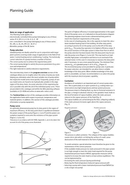
Pump curve<br />
An optimally dimensioned pump has its duty point in the region of<br />
maximum efficiency. At the duty point there is equilibrium between<br />
the power output of the pump (Figure 1, Curve P) and the power consumption<br />
required to overcome the resistance of the pipe system<br />
(Figure 1, Curve A1).<br />
Tolerances in accordance with ISO 9906, Appendix 1, are to be taken into<br />
account for all of the pump curves illustrated.<br />
Figure 1<br />
H<br />
[m]<br />
P 2<br />
[kW]<br />
Q min<br />
Q nenn<br />
A 1<br />
Q max<br />
Q[m 3 /h]<br />
P max<br />
Q[m 3 /h]<br />
A 2<br />
The point of highest efficiency is located approximately in the upper<br />
third of the pump curve, or is indicated on the performance diagram.<br />
The planning engineer must locate a dimensioned duty point to<br />
match the maximum requirements of the pump.<br />
In the case of a heating pump, this is the capacity to meet the calculated<br />
standard heating load of the building. All other duty points<br />
occurring in practice lie on the pump curve to the left of the duty<br />
point Q nenn. The pump thus operates in its highest efficiency range. If<br />
the actual resistance of the pipe system is lower than that on which<br />
the pump selection has been based, then the duty point may lie outside<br />
the pump curve (Figure 1, Curve A2). This may lead to an inadmissibly<br />
high power consumption and hence to an overload of the<br />
selected motor. In this case it is necessary to reassess the duty point<br />
and, if necessary, to use a more powerful pump. The minimum flow<br />
volume Q min of a glanded pump is 10 % of Q max (Figure 1).<br />
The incremental pump curves provided for pumps and, in particular,<br />
for power selection, are intended for use when there is reliable<br />
knowledge of the duty point. When reliable knowledge of the duty<br />
point is unavailable, our basic recommendation is to select the pump<br />
with the maximum electrical power capability.<br />
Cavitation<br />
Avoidance of cavitation is an important part of correct pump selection.<br />
This is particularly so in open systems (e. g. cooling tower systems)<br />
and at very high temperatures and low system pressures.<br />
The pressure drop in a flowing fluid, e.g. due to frictional resistance in<br />
the pipe, a change in absolute velocity or the geodetic head, leads to<br />
the local formation of vapour bubbles, when the static pressure<br />
reduces to the vapour pressure of the fluid (Fig. 2).<br />
The vapour bubbles are carried along by the flow, collapsing suddenly<br />
if the static pressure increases again above the vapour pressure<br />
(Fig. 3).<br />
Negative pressure Positive pressure<br />
Figure 2 Figure 3<br />
This process is called cavitation. The collapse of the vapour bubbles<br />
causes micro-jets which, on hitting the surface of a wall, cause<br />
destruction of the wall material in the form of pitting.<br />
To avoid cavitation, special attention must therefore be given to the<br />
maintenance of the correct pressure.<br />
If the available intake pressure (or static pressure) in the pipe system<br />
is not high enough to meet the static head required for the pump<br />
(maintained pressure head or NPSH), appropriate measures will be<br />
required to increase the static head to at least achieve equilibrium. This<br />
can be implemented by:<br />
- Increasing the static pressure (pump positioning).<br />
- Reducing the fluid temperature (reduced vapour pressure pD)<br />
- Selecting a pump with a lower maintained pressure head (NPSH) (as<br />
arule a larger size pump)<br />
6 Subject to change without prior notice 09/2006 WILO AG