SD6 Leistungskit für 3.0 CRD - startech
SD6 Leistungskit für 3.0 CRD - startech
SD6 Leistungskit für 3.0 CRD - startech

Erfolgreiche ePaper selbst erstellen
Machen Sie aus Ihren PDF Publikationen ein blätterbares Flipbook mit unserer einzigartigen Google optimierten e-Paper Software.
Montageanleitung<br />
<strong>Leistungskit</strong> <strong>SD6</strong><br />
LX-<strong>SD6</strong>-00<br />
Chrysler<br />
300 C<br />
<strong>3.0</strong> <strong>CRD</strong><br />
LX<br />
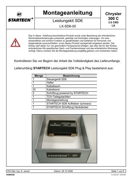
Das in dieser Anleitung beschriebene Produkt wurde unter Beachtung der erforderlichen<br />
Sicherheitsanforderungen entwickelt, gefertigt und Kontrollen unterzogen. Um eine<br />
einwandfreie und sichere Funktion zu gewährleisten und Gefahren <strong>für</strong> Personen und<br />
Gegenstände auszuschließen, muss dieses Produkt sachgemäß eingebaut werden. Der<br />
Einbau darf daher nur von geschultem Fachpersonal erfolgen, das über die <strong>für</strong> den Einbau<br />
erforderlichen Kfz-spezifischen Sach- und Fachkenntnisse und das erforderliche Werkzeug<br />
verfügt. Hierzu müssen Sie die Montageanleitung sorgfältig gelesen und verstanden haben.<br />
Kontrollieren Sie vor Beginn der Arbeit die Vollständigkeit des Lieferumfangs.<br />
Lieferumfang STARTECH <strong>Leistungskit</strong> <strong>SD6</strong> Plug & Play bestehend aus:<br />
Menge Bezeichnung<br />
1 Steuergerät <strong>SD6</strong><br />
1 Halter<br />
1 Kabelbaum<br />
20 Kabelband<br />
2 Schriftzug powered by STARTECH<br />
1 TÜV-Teilegutachten<br />
1 Montageanleitung<br />
1 STARTECH <strong>SD6</strong> Aufkleber (schwarz)<br />
1 STARTECH Schriftzug Heckdeckel<br />
V02 Dipl. Ing. S. Janert Datum: 26.10.2006 Seite 1 von 6<br />
STARTECH Formblatt-Nr.: 026/04/06
(Abb.: 1)<br />
Montageanleitung<br />
<strong>Leistungskit</strong> <strong>SD6</strong><br />
LX-<strong>SD6</strong>-00<br />
Steckerübersicht/Kabelverlegungsplan<br />
1. Stecker <strong>SD6</strong> Steuergerät<br />
2. Den roten Bereich nicht knicken!!!<br />
3. Anschluss an die Fahrzeugmasse (Kabelschuh)<br />
4. Stecker/Gegenstecker, 3 pol. <strong>für</strong> Raildrucksensor<br />
5. Stecker/Gegenstecker, 2 pol. <strong>für</strong> Mengenregelventil<br />
6. Stecker/Gegenstecker, 2 pol. <strong>für</strong> Injektor Zyl. 4<br />
7. Stecker/Gegenstecker, 3 pol. <strong>für</strong> Ladedrucksensor<br />
8. Stecker/Gegenstecker, 2 pol. <strong>für</strong> Injektor Zyl. 1<br />
3.<br />
1.<br />
(Abb.: 2)<br />
(Abb.: 2)<br />
3.<br />
2.<br />
4.<br />
2.<br />
8.<br />
1.<br />
Chrysler<br />
300 C<br />
<strong>3.0</strong> <strong>CRD</strong><br />
LX<br />
V02 Dipl. Ing. S. Janert Datum: 26.10.2006 Seite 2 von 6<br />
STARTECH Formblatt-Nr.: 026/04/06<br />
4.<br />
7.<br />
6.<br />
6.<br />
5.<br />
8.<br />
7.<br />
5.
Montageanleitung<br />
<strong>Leistungskit</strong> <strong>SD6</strong><br />
LX-<strong>SD6</strong>-00<br />
Anschluss Mengenregelventil<br />
Chrysler<br />
300 C<br />
<strong>3.0</strong> <strong>CRD</strong><br />
LX<br />
1. Verlegen Sie den <strong>SD6</strong> - Kabelbaum wie in Abb.: 2 dargestellt. Befestigen Sie diesen erst,<br />
wenn Sie alle Stecker verbunden haben, mit den beigelegten Kabelbindern.<br />
2. Ziehen Sie den Originalstecker des Mengenregelventils ab und verbinden<br />
Sie diesen mit dem Gegenstecker 5 des <strong>SD6</strong> - Kabelbaumes. Verbinden Sie den Stecker 5<br />
mit dem Mengenregelventil. (siehe Abb.1,2,3).<br />
3. Befestigen Sie die Steckverbindung mit einem Kabelband am Fahrzeugkabelbaum<br />
des Mengenregelventils.<br />
5.<br />
(Abb.: 3)<br />
(Abb.: 4)<br />
Anschluss Ladedrucksensor<br />
4. Ziehen Sie den Originalstecker des Ladedrucksensors ab und verbinden<br />
Sie diesen mit dem Gegenstecker 7 des <strong>SD6</strong> – Kabelbaumes. Verbinden Sie den Stecker 7<br />
mit dem Ladedrucksensor (siehe Abb. 1,2,4).<br />
5. Befestigen Sie die Steckverbindung mit einem Kabelband am Fahrzeugkabelbaum<br />
des Ladedrucksensors.<br />
Achten Sie darauf, dass die elektrischen Leitungen vor<br />
Beschädigungen und hohen Temperaturen geschützt sind und<br />
kontrollieren Sie nochmals den korrekten Sitz der Anschlussstecker.<br />
V02 Dipl. Ing. S. Janert Datum: 26.10.2006 Seite 3 von 6<br />
STARTECH Formblatt-Nr.: 026/04/06<br />
7.
Montageanleitung<br />
<strong>Leistungskit</strong> <strong>SD6</strong><br />
LX-<strong>SD6</strong>-00<br />
Anschluss Injektoren 1,4<br />
Chrysler<br />
300 C<br />
<strong>3.0</strong> <strong>CRD</strong><br />
LX<br />
1. Ziehen Sie den Originalstecker des Injektors vom Zyl. 1 (siehe Abb.: 7) ab und verbinden Sie<br />
diesen mit dem Gegenstecker 8 des <strong>SD6</strong> – Kabelbaumes. Verbinden Sie den Stecker 8 mit<br />
dem Injektor des 1. Zylinders (siehe Abb.: 1,2,5).<br />
2. Ziehen Sie den Originalstecker des Injektors vom Zyl. 4 (siehe Abb.: 7) ab und verbinden Sie<br />
diesen mit dem Gegenstecker 6 des <strong>SD6</strong> – Kabelbaumes. Verbinden Sie den Stecker 6 mit<br />
dem Injektor des 4. Zylinders (siehe Abb.: 1,2,6).<br />
3. Befestigen Sie die Steckverbindungen und die Leitungen mit Kabelbändern an den<br />
Metallkraftstoffleitungen.<br />
(Abb.: 5)<br />
8.<br />
(Abb.: 6)<br />
Schematische Darstellung: Zylinder-Anordnung<br />
3<br />
2<br />
(Abb.: 7)<br />
M<br />
O<br />
T<br />
O<br />
6<br />
5<br />
1 R<br />
4<br />
Achten Sie darauf, dass die elektrischen Leitungen vor<br />
Beschädigungen und hohen Temperaturen geschützt sind und<br />
kontrollieren Sie nochmals den korrekten Sitz der Anschlussstecker.<br />
V02 Dipl. Ing. S. Janert Datum: 26.10.2006 Seite 4 von 6<br />
STARTECH Formblatt-Nr.: 026/04/06<br />
Fahrtrichtung<br />
6.
Montageanleitung<br />
<strong>Leistungskit</strong> <strong>SD6</strong><br />
LX-<strong>SD6</strong>-00<br />
Anschluss Raildrucksensor<br />
Chrysler<br />
300 C<br />
<strong>3.0</strong> <strong>CRD</strong><br />
LX<br />
1. Ziehen Sie den Originalstecker des Raildrucksensors ab und verbinden Sie diesen mit dem<br />
Gegenstecker 4 des <strong>SD6</strong> – Kabelbaumes. Verbinden Sie den Stecker 4 mit dem<br />
Raildrucksensor (siehe Abb. 1,2,8).<br />
2. Befestigen Sie die Steckverbindung mit einem Kabelbinder.<br />
(Abb.: 8)<br />
4.<br />
Achten Sie darauf, dass die elektrischen Leitungen vor<br />
Beschädigungen und hohen Temperaturen geschützt sind und<br />
kontrollieren Sie nochmals den korrekten Sitz der Anschlussstecker.<br />
V02 Dipl. Ing. S. Janert Datum: 26.10.2006 Seite 5 von 6<br />
STARTECH Formblatt-Nr.: 026/04/06
Montageanleitung<br />
<strong>Leistungskit</strong> <strong>SD6</strong><br />
LX-<strong>SD6</strong>-00<br />
Anschluss / Montageort des <strong>SD6</strong> Steuergerätes<br />
(Abb.: 9)<br />
Chrysler<br />
300 C<br />
<strong>3.0</strong> <strong>CRD</strong><br />
LX<br />
1. Verlegen Sie den <strong>SD6</strong> – Kabelbaum zum Montageort des <strong>SD6</strong> Steuergerätes (siehe Abb.:<br />
9).<br />
2. Befestigen Sie das <strong>SD6</strong> Steuergerät in dem Halter und verbinden Sie dieses mit dem<br />
Kabelbaum. Reinigen Sie die Klebefläche, sodass diese schmutz-, fett -und wachsfrei ist.<br />
Kleben Sie nun das <strong>SD6</strong> Steuergerät mit dem Stecker nach unten an die in Abb.: 9 gezeigte<br />
Stelle. Nachdem Sie das Steuergerät angeklebt haben nehmen Sie dieses aus dem Halter<br />
und drücken diesen fest an die Motorraumwand. Stecken Sie das Steuergerät wieder in den<br />
Halter.<br />
3. Verschrauben Sie den Kabelschuh 3. des schwarzen Kabels mit der Fahrzeugmasse (siehe<br />
Abb.: 2).<br />
4. Zu lange Kabel des <strong>SD6</strong> - Kabelbaumes sind durch Schlaufen (Kabelbaum nicht kürzen!)<br />
entsprechend in der Länge zu ändern bis zum Montageort des <strong>SD6</strong> - Steuergerätes.<br />
5. Kontrollieren Sie zum Schluss alle Steckverbindungen.<br />
6. Kleben Sie den STARTECH <strong>SD6</strong> Aufkleber auf die Motorabdeckung und die powered by<br />
STARTECH Schriftzüge unter die Seitenblinker.<br />
7. Führen Sie eine Probefahrt durch.<br />
Achten Sie darauf, dass die elektrischen Leitungen vor<br />
Beschädigungen und hohen Temperaturen geschützt sind und<br />
kontrollieren Sie nochmals den korrekten Sitz der Anschlussstecker.<br />
V02 Dipl. Ing. S. Janert Datum: 26.10.2006 Seite 6 von 6<br />
STARTECH Formblatt-Nr.: 026/04/06
Fitting instructions<br />
STARTECH Performance Kit <strong>SD6</strong><br />
Part-no.: LX-<strong>SD6</strong>-00<br />
Chrysler<br />
300 C<br />
<strong>3.0</strong> <strong>CRD</strong><br />
LX<br />
The product described in the instructions was developed, produced and checked<br />
considering the necessary safety requirements. In order to ensure a proper and<br />
safe function and rule out danger for persons and things, this product must be<br />
installed appropriately. Only trained, qualified staff, having the necessary<br />
technical/mechanical know-how and tools, are allowed to perform the installation.<br />
Therefore you must carefully read and understand the instructions.<br />
Before you start work, please check the extent of supply.<br />
Included in delivery of STARTECH performance kit <strong>SD6</strong> Plug & Play:<br />
Quantity Description<br />
1 control unit <strong>SD6</strong><br />
1 bracket<br />
1 wiring loom<br />
20 cable ties<br />
2 Powered by STARTECH writing<br />
1 TÜV-Certificate<br />
1 fitting instructions<br />
1 STARTECH <strong>SD6</strong> sticker (black)<br />
1 STARTECH writing trunk lid<br />
V02 Dipl. Ing. S. Janert Date: 26.10.2006 Page 1 of 6<br />
STARTECH Formblatt-Nr.: 026/04/06
(Fig.: 1)<br />
Fitting instructions<br />
STARTECH Performance Kit <strong>SD6</strong><br />
3.<br />
Part-no.: LX-<strong>SD6</strong>-00<br />
Overview of Wiring loom<br />
2.<br />
1.<br />
Chrysler<br />
300 C<br />
<strong>3.0</strong> <strong>CRD</strong><br />
LX<br />
1. Connection for <strong>SD6</strong> control unit<br />
2. Do not kink or sharply bend the cable in the red taped area!!!<br />
3. Connection to the vehicle ground/earth (terminal end)<br />
4. Male / Female connection for the common-rail-pressure sensor (3 pole)<br />
5. Male / Female connection for the quantity control valve (2 pole)<br />
6. Male / Female connection for the Piezo injector 4th Cylinder (2 pole)<br />
7. Male / Female connection for the boost-pressure sensor (3 pole)<br />
8. Male / Female connection for the Piezo injector 1st cylinder ( 2 pole)<br />
V02 Dipl. Ing. S. Janert Date: 26.10.2006 Page 2 of 6<br />
STARTECH Formblatt-Nr.: 026/04/06<br />
4.<br />
6.<br />
8.<br />
7.<br />
5.
Fitting instructions<br />
STARTECH Performance Kit <strong>SD6</strong><br />
LHD – left hand drive<br />
(Fig.: 2a)<br />
3.<br />
Part-no.: LX-<strong>SD6</strong>-00<br />
Overview of Wiring plan<br />
Chrysler<br />
300 C<br />
<strong>3.0</strong> <strong>CRD</strong><br />
LX<br />
1. Connection for <strong>SD6</strong> control unit<br />
2. Do not kink or sharply bend the cable in the red taped area!!!<br />
3. Connection to the vehicle ground/earth (terminal end)<br />
4. Male / Female connection for the common-rail-pressure sensor (3 pole)<br />
5. Male / Female connection for the quantity control valve (2 pole)<br />
6. Male / Female connection for the Piezo injector 4th Cylinder (2 pole)<br />
7. Male / Female connection for the boost-pressure sensor (3 pole)<br />
8. Male / Female connection for the Piezo injector 1st cylinder ( 2 pole)<br />
(Fig.: 2b)<br />
1.<br />
3.<br />
1.<br />
2.<br />
8.<br />
RHD – right hand drive<br />
4.<br />
8.<br />
2. 7.<br />
V02 Dipl. Ing. S. Janert Date: 26.10.2006 Page 3 of 6<br />
STARTECH Formblatt-Nr.: 026/04/06<br />
4.<br />
7.<br />
6.<br />
6.<br />
5.<br />
5.
Fitting instructions<br />
STARTECH Performance Kit <strong>SD6</strong><br />
Part-no.: LX-<strong>SD6</strong>-00<br />
Connection at the quantity control valve<br />
Chrysler<br />
300 C<br />
<strong>3.0</strong> <strong>CRD</strong><br />
LX<br />
9. Route the <strong>SD6</strong> wiring loom as shown in Fig. 2a or Fig. 2b. Do not fasten it with the supplied<br />
cable ties until all plugs have been connected.<br />
10. Pull off the original plug of the control valve and connect this with the female plug No. 5 of<br />
the <strong>SD6</strong> wiring loom. Connect the male plug No. 5 to the control valve (Fig.:1,2,3)<br />
11. Fasten the connectors with a cable tie onto the vehicle wiring loom of the quantity control<br />
valve<br />
(Fig.: 3)<br />
5.<br />
(Fig.: 4)<br />
Connection at the boost-pressure sensor<br />
12. Pull off the original connector of the boost-pressure sensor and connect this with the female<br />
plug No. 7 of the <strong>SD6</strong> wiring loom. Connect the male plug No. 7 with the boost-pressure<br />
sensor.(Fig.:1,2,4)<br />
13. Fasten the connectors with a cable tie onto the vehicle wiring loom of the boost-pressure<br />
sensor.<br />
Please take care that the wiring is protected at all times from possible<br />
damage and high temperatures. Always re-check all connections, making<br />
sure that these are correctly and completely fastened.<br />
V02 Dipl. Ing. S. Janert Date: 26.10.2006 Page 4 of 6<br />
STARTECH Formblatt-Nr.: 026/04/06<br />
7.
Fitting instructions<br />
STARTECH Performance Kit <strong>SD6</strong><br />
Part-no.: LX-<strong>SD6</strong>-00<br />
Connections at the injectors 1 & 4<br />
Chrysler<br />
300 C<br />
<strong>3.0</strong> <strong>CRD</strong><br />
LX<br />
14. Pull off the original plug of the injector for cyl. 1 (Fig.: 7) and connect it with the female plug<br />
No. 8 of the <strong>SD6</strong> wiring loom. Connect the male plug No. 8 with the injector for cyl. 1.<br />
(pic.:1,2,5)<br />
15. Pull off the original plug of the injector for cyl. 4 (Fig.:7) and connect it with the female plug<br />
No. 6 of the <strong>SD6</strong> wiring loom. Connect the male plug No. 6 with the injector for cyl. 4.<br />
(Fig.:1,2,6)<br />
16. Fasten the connectors with cable ties onto the metal fuel lines.<br />
8.<br />
(Fig.: 5)<br />
(Fig.: 6)<br />
Schematic: Clyinder configuration<br />
3<br />
2<br />
(Fig.: 7)<br />
E<br />
n<br />
g<br />
i<br />
n<br />
6<br />
5<br />
1 e 4<br />
Please take care that the wiring is protected at all times from possible<br />
damage and high temperatures. Always re-check all connections, making<br />
sure that these are correctly and completely fastened.<br />
V02 Dipl. Ing. S. Janert Date: 26.10.2006 Page 5 of 6<br />
STARTECH Formblatt-Nr.: 026/04/06<br />
Driving Direc.<br />
6.
Fitting instructions<br />
STARTECH Performance Kit <strong>SD6</strong><br />
Part-no.: LX-<strong>SD6</strong>-00<br />
Connection at the common-rail-pressure sensor<br />
Chrysler<br />
300 C<br />
<strong>3.0</strong> <strong>CRD</strong><br />
LX<br />
17. Pull off the original plug of the rail-pressure sensor and connect it to the female plug No. 4 of<br />
the <strong>SD6</strong> wiring loom. Connect the male plug No. 4 with the rail-pressue sensor. (Fig.: 1,2,8)<br />
18. Fasten the connections with a cable tie.<br />
(Fig.: 8)<br />
4.<br />
Please take care that the wiring is protected at all times from possible<br />
damage and high temperatures. Always re-check all connections, making<br />
sure that these are correctly and completely fastened.<br />
V02 Dipl. Ing. S. Janert Date: 26.10.2006 Page 6 of 6<br />
STARTECH Formblatt-Nr.: 026/04/06
Fitting instructions<br />
STARTECH Performance Kit <strong>SD6</strong><br />
Part-no.: LX-<strong>SD6</strong>-00<br />
Connection / Postion of the <strong>SD6</strong> control unit<br />
19. Route the <strong>SD6</strong> wiring loom to the location of the <strong>SD6</strong> control unit (Fig.: 9).<br />
Chrysler<br />
300 C<br />
<strong>3.0</strong> <strong>CRD</strong><br />
LX<br />
20. Clip the <strong>SD6</strong> control unit into the fastening bracket and then connect the <strong>SD6</strong> control unit with<br />
the wiring loom. Clean the surface to be adhered so that it is free of dirt, grease and wax.<br />
Adhere the control unit with bracket, wiring loom facing downwards, onto the indicated area<br />
(Fig.:9). After adhering the control unit with bracket remove the control unit from the bracket<br />
and press down firmly on the empty bracket so that it will adhere to the fitting point.<br />
21. Fasten the cable end No. 3. of the black cable with the vehicle ground/earth (Fig.: 2).<br />
22. Extra cable length of the <strong>SD6</strong> wiring loom can be shortened by looping the cable (do not cut<br />
the cable!) until the length is appropriate.<br />
23. Final check of all connections.<br />
24. Refit all removed parts ensuring good fit.<br />
25. Stick the STARTECH <strong>SD6</strong> sticker onto the engine cover and the powered by STARTECH<br />
writings under the side blinker.<br />
26. Make a Test drive.<br />
(Fig.: 9)<br />
Please take care that the wiring is protected at all times from possible<br />
damage and high temperatures. Always re-check all connections, making<br />
sure that these are correctly and completely fastened.<br />
V02 Dipl. Ing. S. Janert Date: 26.10.2006 Page 7 of 6<br />
STARTECH Formblatt-Nr.: 026/04/06