AZBox Ultra HD Wiederbelebung

Sie wollen auch ein ePaper? Erhöhen Sie die Reichweite Ihrer Titel.
YUMPU macht aus Druck-PDFs automatisch weboptimierte ePaper, die Google liebt.
1<br />
2<br />
3<br />
4 5<br />
Die älteren <strong>AZBox</strong> Receiver, zu denen<br />
auch mein <strong>Ultra</strong> <strong>HD</strong> gehörte, verfügen<br />
über eine interne serielle Schnittstelle.<br />
Über diese kann man sich in den Bootloader<br />
einklinken und die Firmware erneut<br />
flashen. Doch ganz so einfach ist es<br />
nicht, denn die interne serielle Schnittstelle<br />
funktioniert mit TTL-Pegeln (3.3<br />
Volt) statt den üblichen 12 Volt einer<br />
RS232 Schnittstelle. Würde man direkt<br />
die interne serielle Schnittstelle des Receivers<br />
mit einem Nullmodem-Kabel an<br />
den COM-Port des Computers anschließen,<br />
dann wäre ein Hardware-Defekt<br />
vorprogrammiert. Man braucht also in<br />
diesem Fall einen TTL-Adapter, wie man<br />
sie z.B. sehr günstig bei eBay für unter<br />
2 Euro ersteigern kann. Es handelt sich<br />
um einen USB-TTL Adapter, der am PC<br />
automatisch als COM-Port erkannt wird.<br />
Diese Adapter benutzen den bekannten<br />
Prolific 2303 Chip, der auch in den meisten<br />
USB-RS232 Adaptern vorkommt.<br />
Einziger Unterschied ist, dass in diesem<br />
Fall noch ein MAX232 für die Pegel-<br />
Wandlung zum Einsatz kommt.<br />
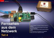
Aber ich entschied mich für eine andere<br />
Lösung: ich benutzte ein altes No-<br />
kia DLR-2L Datenkabel. Da ich das Kabel<br />
sowieso nicht mehr benutze schnitt ich<br />
einfach den Nokia-Stecker ab. Durch<br />
Probieren am Oszilloskop konnte ich<br />
schnell ermitteln, dass der rote Leiter<br />
RX, der grüne TX und der schwarze<br />
Leiter wie erwartet GND überträgt. Ein<br />
altes CD-ROM Audiokabel für Computer<br />
bietet einen passenden Stecker für die<br />
<strong>AZBox</strong>, so dass die entsprechenden Leiter<br />
nur noch verbunden werden mussten.<br />
Nach einem ersten Test fiel mir<br />
natürlich gleich der jedem Bastler bekannte<br />
einschlägige Fehler jeder seriellen<br />
Übertragung auf: TX und RX müssen<br />
natürlich gekreuzt verbunden werden.<br />
Und dann funktionierte es auch schon.<br />
Mit Putty, einem sehr bekannten Freeware<br />
Terminal-Programm, konnte ich<br />
den Bootloader der <strong>AZBox</strong> verfolgen und<br />
dieser meldete eine ungültige Firmware.<br />
Dieser Bootloader nennt sich YAMON<br />
(„Yet Another MONitor“) und ist viel umfangreicher<br />
als gewöhnliche Bootloader<br />
älterer Receiver und bietet eine Kommando-Ebene,<br />
die es unter anderem erlaubt,<br />
über das Netzwerk Dateien in den<br />
RAM-Speicher zu lesen oder von diesem<br />
6<br />
1. The Nokia DLR-2L cable features a TTL<br />
to RS232 converter and can be used to<br />
connect the COM-Port of a PC with a TTL<br />
interface. If your computer does not have<br />
a COM-port anymore, you can just use a<br />
RS232 to USB converter. Bear in mind that<br />
neither the Nokia-cable, nor the RS232 to<br />
USB converter cross the TX and RX lines:<br />
you will need to cross them yourself. Pay<br />
special attention to just use TX, RX and<br />
GND. The second pin on the <strong>AZBox</strong> PCB<br />
is not to be used. Doing so can quickly<br />
fry the circuit on the <strong>AZBox</strong> and then<br />
you are definitely locked out of any TTL<br />
restoration.<br />
2. See the white dot on the PCB, close to<br />
the 4 TTL pins? It marks the pin #1. On the<br />
different <strong>AZBox</strong> receivers the pins have<br />
always the same function:<br />
Pin 1 – TX<br />
Pin 2 – VCC (Warning: do not use this pin!)<br />
Pin 3 – GND<br />
Pin 4 – RX<br />
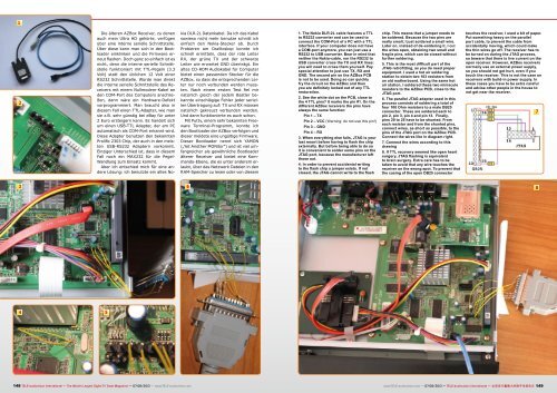
3. When everything else fails, JTAG is your<br />
last resort before having to flash the chip<br />
externally. But before being able to do so<br />
it is convenient to solder some pins on the<br />
JTAG port, because the manufacturer left<br />
those out.<br />
4. In order to prevent accidental writing<br />
to the flash chip a jumper exists. If not<br />
closed, the JTAG cannot write to the flash<br />
chip. This means that a jumper needs to<br />
be soldered. Because the two pins are<br />
really small, I just soldered a small wire.<br />
Later on, instead of de-soldering it, I cut<br />
the wires open, obtaining two small and<br />
fragile pins, which can be closed without<br />
further soldering.<br />
5. This is the most difficult part of the<br />
JTAG retrofitting, as you do need proper<br />
equipment. I used a hot air soldering<br />
station to obtain two 103 resistors from<br />
an old motherboard. Using the same hot<br />
air station, I soldered these two miniscule<br />
resistors to the <strong>AZBox</strong> PCB, close to the<br />
JTAG port.<br />
6. The parallel JTAG adapter used in this<br />
process consists of soldering a total of<br />
four 100 Ohm resistors to a male DB25<br />
connector. These are soldered each to<br />
pin 2, pin 3, pin 4 and pin 13. Finally,<br />
pins 20 to 25 have to be shunted. From<br />
each resistor and from the shunted pins,<br />
connect wires, as short as possible, to the<br />
pins of the JTAG port on the <strong>AZBox</strong> PCB.<br />
Connect the wires like in diagram right.<br />
7. Connect the wires according to this<br />
drawing<br />
8. If TTL recovery seemed like open heart<br />
surgery, JTAG flashing is equivalent<br />
to brain surgery. Extra care has to be<br />
taken to avoid that any wire touches the<br />
receiver on the wrong spot. To prevent that<br />
the casing of the open DB25 connector<br />
touches the receiver, I used a bit of paper.<br />
Put something heavy on the parallel<br />
port cable, to prevent the cable from<br />
accidentally moving, which could make<br />
the thin wires go off. The receiver has to<br />
be turned on during the JTAG process,<br />
so beware that there is live current on the<br />
open receiver. However, <strong>AZBox</strong> receivers<br />
normally use an external power supply,<br />
so you should not get hurt, even if you<br />
touch the receiver. This is not the case on<br />
receivers with build-in power supply. In<br />
these cases you have to be extra careful<br />
and advise other people in the house to<br />
not get near the receiver.<br />
148 TELE-audiovision International — The World‘s Largest Digital TV Trade Magazine — 07-08/2013 — www.TELE-audiovision.com www.TELE-audiovision.com — 07-08/2013 — TELE-audiovision International — 全球发行量最大的数字电视杂志 149<br />
7<br />
8