Trumatic S 3002 FS
Trumatic S 3002 FS
Trumatic S 3002 FS

Sie wollen auch ein ePaper? Erhöhen Sie die Reichweite Ihrer Titel.
YUMPU macht aus Druck-PDFs automatisch weboptimierte ePaper, die Google liebt.
<strong>Trumatic</strong> S <strong>3002</strong> <strong>FS</strong><br />
Gebrauchsanweisung Seite 2<br />
Montageanweisung Seite 6<br />
Operating instructions Page 10<br />
Installation instructions Page 14<br />
Komfort für unterwegs
Verwendungszweck<br />
Die Flüssiggasheizung <strong>Trumatic</strong> S <strong>3002</strong> <strong>FS</strong> wurde für die<br />
stationäre Montage in fest ausgebauten Vorzelten konstruiert.<br />
Der Betrieb der Heizung ist nur zulässig, wenn die Gasversorgung<br />
(30 mbar) über das Fahrzeug (Caravan / Motorcaravan)<br />
erfolgt (z. B. über Gas-Außensteckdose).<br />
2<br />
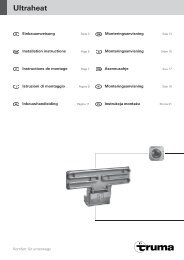
<strong>Trumatic</strong> S <strong>3002</strong> <strong>FS</strong><br />
Flüssiggasheizung zur freistehenden Aufstellung in festausgebauten Vorzelten<br />
7<br />
6<br />
Der Einbau in Kraftfahrzeuge (Reisemobile) oder Kraftomnibusse<br />
ist nicht zulässig.<br />
Die Heizung hat einen zum Aufstellungsraum geschlossenen<br />
Verbrennungsluft-/Abgaskreislauf.<br />
Weitere Anwendungen sind nur nach Rücksprache mit Truma<br />
möglich.<br />
Wichtige Bedienungshinweise<br />
1. Die Verbrennungsluft-An saugung (2) muss von Schmutz<br />
und Schneematsch freigehalten werden.<br />
2. Im Winter muss vor dem Zünden der Kamin (4) vom<br />
Schnee befreit werden.<br />
1<br />
5<br />
3<br />
8<br />
7<br />
4<br />
2<br />
6<br />
1 Flüssiggasheizung <strong>Trumatic</strong> S <strong>3002</strong> <strong>FS</strong><br />
2 Verbrennungsluft-Ansaugung<br />
3 Abgasrohr mit Überrohr<br />
4 Abgaskamin<br />
5 Trumavent Gebläse TEB 2<br />
6 Warmluftrohre<br />
7 Warmluftaustritte<br />
8 Gaszufuhr<br />
3. Das Abgas- und Verbrennungsluftzuführungsrohr sowie alle<br />
An schlüsse müssen regelmäßig, in jedem Fall nach Verpuffungen<br />
(Fehlzündungen), überprüft werden. Das Abgasrohr<br />
muss unbedingt auf ganzer Länge steigend und mit mehreren<br />
Schellen fest montiert verlegt sein. Auf keinen Fall dürfen<br />
Gegenstände auf das Abgasrohr gelegt werden, da dies zu<br />
Beschädigungen führen könnte. Das Abgasrohr muss sowohl<br />
an der Heizung wie am Kamin dicht und fest angeschlossen<br />
sein. Heizungen mit falsch montierten oder beschädigten Abgasrohren<br />
dürfen nicht mehr betrieben werden!<br />
4. Der Warmluftaustritt an der Heizung darf unter keinen<br />
Umständen behindert werden. Deshalb keinesfalls<br />
Textilien o.ä. zum Trocknen vor oder auf die Heizung hängen.<br />
Solche Zweckentfrem dung könnte Ihre Heizung durch die<br />
dabei hervorgerufene Überhitzung schwer be schädigen. Keine<br />
brennbaren Gegenstände in die Nähe der Heizung bringen!<br />
Bitte beachten Sie dies im Interesse Ihrer Sicherheit.<br />
Bauartbedingt wird während des Betriebes die<br />
Heizungsverkleidung heiß. Die Sorgfaltspflicht<br />
gegen über Dritten (insbesondere Kleinkindern)<br />
obliegt dem Betreiber.
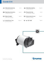
Gebrauchsanweisung<br />
Vor Inbetriebnahme unbedingt Gebrauchsanweisung<br />
und „Wichtige Bedienungs hinweise“ beachten!<br />
a = Bedienungsgriff<br />
(Thermostat)<br />
b = Integriertes Bedienteil für<br />
Trumavent Gebläse TEB<br />
c = Schnellschlussventil für<br />
die Gaszufuhr<br />
d = Zündautomat mit<br />
Batteriefach<br />
e = Zündfernanzeige<br />
(Zubehör)<br />
f = Sichtfenster zum<br />
Beobachten der Flamme<br />
g = Thermostatfühler<br />
h = Fabrikschild<br />
(Verkleidung abnehmen!)<br />
Inbetriebnahme der Heizung<br />
Vor der ersten Inbetriebnahme sicher stellen, dass eine Batterie<br />
eingelegt ist (siehe Wartung, Punkt „Batteriewechsel“)!<br />
1. Gasflasche und Schnellschlussventil<br />
in der Gaszuleitung<br />
öffnen.<br />
2. Den Bedienungsgriff (a)<br />
in Thermostatstellung 1 – 10<br />
drehen und bis zum Anschlag<br />
niederdrücken. Die Zündung<br />
erfolgt automatisch (Zünd funke<br />
hörbar), bis die Flamme brennt.<br />
e<br />
h<br />
b<br />
d<br />
10<br />
0<br />
9<br />
f<br />
8<br />
a<br />
g<br />
. .<br />
Den Bedienungsgriff noch bis zu 10 Sekunden gedrückt halten,<br />
damit die Zündsicherung anspricht.<br />
Bei Störungen vor erneutem Zünd versuch mindestens<br />
2 Minuten warten!<br />
Sollte die Flamme wieder verlöschen, erfolgt während<br />
der Schließzeit der Zündsicherung (ca. 30 Sekunden) eine<br />
sofortige Wiederzündung.<br />
Wenn keine Flamme zustande kommt, arbeitet der Zündautomat<br />
weiter, bis am Be dienungsgriff (a) auf „0” ge schaltet wird.<br />
Falls die Gaszuleitung luftgefüllt ist, kann es bis zu zwei Minuten<br />
dauern, bis Gas zur Verbrennung bereitsteht. Während<br />
dieser Zeit ist der Bedienungsgriff gedrückt zu halten, bis die<br />
Flamme brennt.<br />
Zur optischen Kontrolle des Zündvorgangs lässt sich die<br />
Heizung problemlos mit einer Zündfernanzeige (e), nachrüsten<br />
(Art.-Nr. 30040-65000).<br />
.<br />
.<br />
7<br />
1<br />
6<br />
.<br />
.<br />
5<br />
2<br />
3<br />
.<br />
4<br />
.<br />
.<br />
c<br />
a<br />
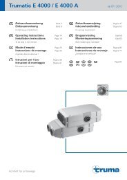
Inbetriebnahme des Gebläses<br />
Um eine gleichmäßige und rasche Warmluftverteilung<br />
sowie eine Absenkung der Oberflächentemperaturen<br />
am Heizgerät sicherzustellen, empfehlen wir, die Heizung immer<br />
mit laufendem Trumavent Gebläse zu betreiben.<br />
k = Handregelung<br />
(z. B. für Ventilation)<br />
Gewünschte Leistung am<br />
Drehknopf einstellen.<br />
l = Aus<br />
m = Automatikbetrieb<br />
(Heizen)<br />
Die Leistung gleicht sich stufenlos der jeweiligen Wärmeabgabe<br />
der Heizung an. Die Höchstleistung kann nach Wunsch am<br />
Drehknopf begrenzt werden. Die Regelung zwischen diesem<br />
Wert und Langsamlauf erfolgt automatisch.<br />
Über die Luftklappe (n) lässt<br />
sich die Luftmenge individuell<br />
zur Warmluftverteilung<br />
einstellen. In der Mittelstellung<br />
verteilt sich die Warmluft<br />
zu 50 % auf die beiden<br />
Ausgänge.<br />
Zur Verstellung der<br />
Luftklappe muss der<br />
Heizungskasten an der<br />
Rückwand gelöst werden.<br />
Bei unterschiedlich langen Lüfterrohren oder auf Seiten mit<br />
höherem Wärmebedarf ist das Lüfterrohr Ø 72 mm zu verwenden.<br />
Hierdurch kann die volle Luftleistung auf dieser Seite<br />
ausgeschöpft werden. Durch Verstellen der Luftklappe (n)<br />
kann die Luftmenge individuell noch gesteigert werden. Dadurch<br />
wird die Luftleistung auf der anderen Seite reduziert.<br />
Sinkt die Luft lei s tung bzw. erhöht sich das Betriebsgeräusch,<br />
kann das Lüfterrad stark verschmutzt sein<br />
(siehe Wartung, Punkt „Reinigung“)!<br />
Raumthermostat<br />
Eine mittlere Raumtem pe ratur von ca. 22 °C erreicht man<br />
ohne Ge bläsebetrieb mit einer Thermostat ein stellung von<br />
3 – 5. Wir empfehlen für den Be trieb mit Gebläse eine<br />
Thermostateinstellung von 4 – 8.<br />
Die genaue Thermostateinstellung muss nach dem eigenen<br />
Wärmebedürfnis individuell ermittelt werden.<br />
Der Thermostatfühler befindet sich unten an der Heizung.<br />
Bitte beachten Sie, dass kalter Luftzug durch Türspalten<br />
usw. den Thermo stat ungünstig beeinflusst. Solche Störquellen<br />
sind in jedem Fall zu beseitigen, da sonst keine befriedigende<br />
Temperaturregelung gewährleistet ist.<br />
Ausschalten<br />
Den Bedienungsgriff der Heizung auf „0” stellen (der Zündautomat<br />
wird damit gleichzeitig ausgeschaltet). Das Gebläse am<br />
Bedienteil auf „Aus“ (Position l) stellen.<br />
Wird das Gerät längere Zeit nicht benutzt, das Schnellschlussventil<br />
in der Gaszuleitung und die Gasflasche schließen.<br />
3
Wartung<br />
Bei einer Störung wenden Sie sich bitte grundsätzlich an den<br />
Truma Service (siehe Truma Serviceheft oder www.truma.com).<br />
Achtung<br />
Trotz sorgfältiger Fertigung kann die Heizung scharfkantige<br />
Teile enthalten, deshalb bei Wartungs- und<br />
Reinigungsarbeiten immer Schutzhandschuhe<br />
verwenden!<br />
Heizungsverkleidung abnehmen<br />
Die Verkleidung oben nach<br />
vorne ziehen, die Haltefedern<br />
seitlich hochdrücken und<br />
die Verkleidung nach vorne<br />
klappen.<br />
Anschließend die Anschlusskabel<br />
(z. B. für das Warmluftgebläse<br />
sowie für die Zündkontrolllampe)<br />
abstecken.<br />
Zur Montage die Verkleidung<br />
auf die unteren Haltelaschen<br />
(p) stellen und die<br />
elektrischen Anschlusskabel<br />
anstecken. Die Bedienungsstange<br />
von unten in die Griffbuchse<br />
einführen und die<br />
Verkleidung oben einrasten<br />
lassen.<br />
Den Bedienungs griff von<br />
oben so aufstec ken, dass der<br />
Pfeil zur „0“-Stel lung zeigt.<br />
Batteriewechsel am Zündautomat<br />
Sind keine Zündfunken hörbar oder nur in Zeitabständen von<br />
mehr als einer Sekunde (bzw. die Kontrolllampe „e“ – Zubehör –<br />
blinkt nicht), muss die Batterie erneuert werden.<br />
Die Batterie nur bei ausgeschalteter und abgekühlter Heizung<br />
wechseln. Vor Beginn jeder Heizsaison neue Batterie einsetzen!<br />
Heizungsverkleidung abnehmen (siehe<br />
oben), Batterie fachabdeckung nach oben<br />
schieben und Batterie wechseln.<br />
Plus / Minus beachten. Batteriefach wieder<br />
schließen.<br />
Nur eine temperaturbeständige (+70 °C), auslaufsichere<br />
Mignon-Batterie (LR 6, AA, AM 3) verwenden (Art.-Nr.<br />
30030-99200), andere Batterien können Funktionsstörungen<br />
verursachen!<br />
Reinigung<br />
(nur bei ausgeschaltetem und abgekühltem Gerät!)<br />
Es empfiehlt sich, mindestens einmal jährlich vor Beginn der<br />
Heizsaison den sich am Wärmetauscher, an der Bodenplatte<br />
und am Lüfterrad der Trumavent Warmluftanlage ansammelnden<br />
Staub zu entfernen. Das Lüfter rad vorsichtig mit einem<br />
Pin sel oder einer kleinen Bürste reinigen.<br />
4<br />
p<br />
Allgemeine Sicherheitshinweise<br />
Bei Undichtigkeiten der Gasanlage bzw. bei Gasgeruch:<br />
– alle offenen Flammen löschen<br />
– nicht rauchen<br />
– Geräte ausschalten<br />
– Gasflasche schließen<br />
– Fenster und Türe öffnen<br />
– keine elektrischen Schalter betätigen<br />
– die gesamte Anlage von einem Fachmann über prüfen<br />
lassen!<br />
Reparaturen dürfen nur vom Fach mann durchgeführt<br />
werden!<br />
Nach jeder Demontage der Abgasführung muss ein neuer<br />
O-Ring montiert werden!<br />
Zum Erlöschen von Gewährleistungs- und Garantieansprüchen<br />
sowie zum Ausschluss von Haftungsansprüchen führen<br />
insbesondere:<br />
– Veränderungen am Gerät (einschließlich Zubehörteilen),<br />
– Veränderungen an der Abgasführung und am Kamin,<br />
– Verwendung von anderen als Truma Originalteilen als<br />
Ersatz- und Zubehörteile,<br />
– das Nichteinhalten der Einbau- und Gebrauchsanweisung.<br />
Der Betriebsdruck der Flüssiggasversorgung 30 mbar muss<br />
mit dem Betriebsdruck des Gerätes (siehe Fabrikschild)<br />
übereinstimmen.<br />
Aus Sicherheitsgründen empfehlen wir generell, die Gasanlage<br />
alle 2 Jahre von einem Fachmann (z. B. Sachkundiger nach<br />
G 607) auf Funktion und Dichtheit überprüfen zu lassen.<br />
In anderen Ländern müssen die dort geltenden<br />
technischen und administrativen Vorschriften beachtet<br />
werden.<br />
Bei erster Inbetriebnahme eines fabrikneuen Gerätes (bzw.<br />
nach längerer Stillstandzeit) kann kurzzeitig eine leichte<br />
Rauch- und Geruchsentwicklung auftreten. Es ist zweckmäßig,<br />
das Gerät dann sofort mit höchster Leistung brennen zu lassen<br />
und für gute Durchlüftung des Raumes zu sorgen.<br />
Ein ungewohntes Brenner geräusch oder Abheben der Flamme<br />
lässt auf einen Reg lerdefekt schließen und macht eine<br />
Überprüfung des Reglers notwendig.
Technische Daten<br />
ermittelt nach EN 624 bzw. Truma Prüfbedingungen<br />
Gasart<br />
Flüssiggas (Propan / Butan)<br />
Betriebsdruck<br />
30 mbar (siehe Fabrikschild)<br />
Nennwärmeleistung<br />
3400 W<br />
Gasverbrauch<br />
30 – 280 g/h<br />
Betriebsspannung<br />
Heizung: 1,5 V<br />
Gebläse: 12 V<br />
Stromaufnahme<br />
Heizung: 50 mA (Zünden), 0,01 mA (Überwachen)<br />
Gebläse: 0,3 bis 1,0 A<br />
Luftfördermenge<br />
bis 135 m 3 /h (mit Lüfterrohr ÜR Ø 65 mm)<br />
bis 142 m 3 /h (mit Lüfterrohr VR Ø 72 mm)<br />
Gewicht<br />
18,5 kg (inkl. Verkleidung und Gebläse)<br />
Konformitätserklärung<br />
Die Flüssiggasheizung <strong>Trumatic</strong> S <strong>3002</strong> <strong>FS</strong> ist durch den<br />
DVGW baumusterge prüft und erfüllt die EG-Gasge räte-Richtlinie<br />
(90/396/EWG) sowie die mitgeltenden EG-Richtlinien.<br />
Für EU-Länder liegt die Produkt-Ident-Num mer vor:<br />
CE-0085AP0325<br />
EG Typgenehmigung<br />
e1 032603<br />
Technische Änderungen vorbehalten!<br />
Abmessungen<br />
510 mm<br />
ca. 72 mm<br />
ca. 582 mm<br />
713 mm<br />
Ø 73<br />
167<br />
45 mm<br />
375 mm<br />
280 mm<br />
320 mm<br />
210 mm<br />
240 mm<br />
Truma Hersteller-Garantieerklärung<br />
1. Garantiefall<br />
Der Hersteller gewährt Garantie für Mängel des Gerätes, die<br />
auf Material- oder Fertigungsfehler zurückzuführen sind. Daneben<br />
bestehen die gesetzlichen Gewährleistungsansprüche<br />
gegen den Verkäufer fort.<br />
Der Garantieanspruch besteht nicht<br />
– für Verschleißteile und bei natürlicher Abnutzung,<br />
– infolge Verwendung von anderen als Truma Originalteilen<br />
in den Geräten und bei Verwendung ungeeigneter<br />
Gasdruckregler,<br />
– infolge Nichteinhaltung der Truma Einbau- und Gebrauchsanweisungen,<br />
– infolge unsachgemäßer Behandlung,<br />
– infolge unsachgemäßer, nicht von Truma veranlass ter<br />
Transportverpackung.<br />
2. Umfang der Garantie<br />
Die Garantie gilt für Mängel im Sinne von Ziffer 1, die innerhalb<br />
von 24 Monaten seit Abschluss des Kaufvertrages zwischen<br />
dem Verkäufer und dem Endverbraucher eintreten. Der<br />
Hersteller wird solche Mängel durch Nacherfüllung beseitigen,<br />
das heißt nach seiner Wahl durch Nach besserung oder Ersatzlieferung.<br />
Leistet der Hersteller Garantie, beginnt die Garantiefrist<br />
hinsichtlich der reparierten oder ausgetauschten Teile<br />
nicht von neuem, sondern die alte Frist läuft weiter. Weitergehende<br />
Ansprüche, insbesondere Schadensersatzansprüche<br />
des Käufers oder Dritter sind ausgeschlos sen. Die Vorschriften<br />
des Produkthaftungs gesetzes bleiben unberührt.<br />
Die Kosten der Inanspruch nahme des Truma Werks kun dendienstes<br />
zur Beseitigung eines unter die Garantie fallenden<br />
Mangels – insbesondere Transport-, Wege-, Arbeits- und<br />
Materialkosten – trägt der Hersteller, soweit der Kundendienst<br />
innerhalb von Deutschland eingesetzt wird. Kundendiensteinsätze<br />
in anderen Ländern sind nicht von der Garantie gedeckt.<br />
Zusätzliche Kosten aufgrund erschwerter Aus- und Einbaubedingungen<br />
des Gerätes (z. B. Demontage von Möbel- oder<br />
Karosserieteilen) können nicht als Garantieleistung anerkannt<br />
werden.<br />
3. Geltendmachung des Garantiefalles<br />
Die Anschrift des Herstellers lautet:<br />
Truma Gerätetechnik GmbH & Co. KG,<br />
Wernher-von-Braun-Straße 12,<br />
85640 Putzbrunn.<br />
In Deutschland ist bei Störungen grundsätzlich das Truma<br />
Servicezentrum zu benachrichtigen; in anderen Ländern stehen<br />
die jeweiligen Servicepartner zur Verfügung (siehe Truma<br />
Serviceheft oder www.truma.com). Beanstandungen sind näher<br />
zu bezeichnen. Ferner ist die ordnungsgemäß ausgefüllte<br />
Garantie-Urkunde vorzulegen oder die Fabriknummer des<br />
Gerätes sowie das Kaufdatum anzugeben.<br />
Damit der Hersteller prüfen kann, ob ein Garantiefall vorliegt,<br />
muss der Endverbraucher das Gerät auf seine Gefahr zum<br />
Hersteller bringen oder ihm übersenden. Bei Schäden an Heizkörpern<br />
(Wärmetau scher) ist der Gasdruckregler ebenfalls mit<br />
einzusenden.<br />
Bei Einsendung ins Werk hat der Versand per Frachtgut zu erfolgen.<br />
Im Garantiefall übernimmt das Werk die Transportkosten<br />
bzw. Kosten der Einsendung und Rücksendung. Liegt kein<br />
Garantiefall vor, gibt der Hersteller dem Kunden Bescheid und<br />
nennt die vom Hersteller nicht zu übernehmenden Reparaturkosten;<br />
in diesem Fall gehen auch die Versandkosten zu<br />
Lasten des Kunden.<br />
5
6<br />
Montage anweisung<br />
Montage und Reparatur des Gerätes darf nur vom<br />
Fachmann durchgeführt werden. Vor Beginn der Arbeiten<br />
Montageanweisung sorgfältig durchlesen und befolgen!<br />
Achtung<br />
Das Edelstahl-Abgasrohr ist extrem scharfkantig,<br />
verwenden Sie deshalb bei der Verarbeitung immer<br />
Schutzhandschuhe!<br />
Verwendungszweck<br />
Die Flüssiggasheizung <strong>Trumatic</strong> S <strong>3002</strong> <strong>FS</strong> wurde für die<br />
stationäre Montage in fest ausgebauten Vorzelten konstruiert.<br />
Der Betrieb der Heizung ist nur zulässig, wenn die Gasversorgung<br />
(30 mbar) über das Fahrzeug (Caravan / Motorcaravan)<br />
erfolgt (z. B. über Gas-Außensteckdose).<br />
Der Einbau in Kraftfahrzeuge (Reisemobile) oder Kraftomnibusse<br />
ist nicht zulässig.<br />
Die Heizung hat einen zum Aufstellungsraum geschlossenen<br />
Verbrennungsluft-/Abgaskreislauf.<br />
Weitere Anwendungen sind nur nach Rücksprache mit Truma<br />
möglich.<br />
Vorschriften<br />
Zum Erlöschen von Gewährleistungs- und Garantieansprüchen<br />
sowie zum Ausschluss von Haftungsansprüchen führen<br />
insbesondere:<br />
– Veränderungen am Gerät (einschließlich Zubehörteilen),<br />
– Veränderungen an der Abgasführung und am Kamin,<br />
– Verwendung von anderen als Truma Originalteilen als<br />
Ersatz- und Zubehörteile,<br />
– das Nichteinhalten der Einbau- und Gebrauchsanweisung.<br />
Der Betriebsdruck der Gasversorgung, 30 mbar muss<br />
mit dem Betriebsdruck des Gerätes (siehe Fabrikschild)<br />
übereinstimmen.<br />
Aus Sicherheitsgründen empfehlen wir generell, die Gasanlage<br />
alle 2 Jahre von einem Fachmann (z. B. Sachkundiger nach<br />
G 607) auf Funktion und Dichtheit überprüfen zu lassen.<br />
In anderen Ländern müssen die dort geltenden technischen<br />
und administrativen Vorschriften beachtet werden.<br />
Nähere Angaben zu den Vorschriften in den entsprechenden<br />
Bestimmungsländern können über unsere Auslands-Vertretungen<br />
(siehe Truma Serviceheft oder www.truma.com) angefordert<br />
werden.<br />
Zulassung<br />
Konformitätserklärung<br />
Die Flüssiggasheizung <strong>Trumatic</strong> S <strong>3002</strong> <strong>FS</strong> ist durch den<br />
DVGW baumusterge prüft und erfüllt die EG-Gasge räte-Richtlinie<br />
(90/396/EWG) sowie die mitgeltenden EG-Richtlinien.<br />
Für EU-Länder liegt die Produkt-Ident-Num mer vor<br />
CE-0085AP0325<br />
EG Typgenehmigung<br />
e1 032603<br />
Platzwahl<br />
Die Heizung wird freistehend unmittelbar an einer festen<br />
Außenwand aufgestellt und muss mit 6 Schrauben sicher<br />
befes tigt werden. Bei nicht fest ausgebauten Vorzelten muss<br />
die Außenwand mittels geeigneter Hilfskonstruktion verstärkt<br />
werden.<br />
Abgasleitungen und Kamine müssen so installiert sein, dass<br />
das Eindringen von Abgasen nach innen nicht möglich ist.<br />
Falls eine Elektro-Zusatzheizung Truma Ultraheat montiert<br />
wird, den entsprechend vorgestanzten Deckel<br />
entfernen und diese entsprechend der dem Ultraheat beiliegenden<br />
Einbauanweisung im Einbaukasten vormontieren.<br />
Bei der Verlegung des Kabels bitte die Hinweise unter „elektrischer<br />
Anschluss – Kabelverlegung” beachten.<br />
Durchführung für Verbrennungsluft-<br />
Ansaugung und Abgasführung<br />
Die Verbrennungluft wird mittels eines flexiblen Schlauches<br />
Ø 80 mm unmittelbar hinter der Heizung durch die Seitenwand<br />
von außen angesaugt. Eine Ansaugung der Verbrennungsluft<br />
aus dem Innenraum ist nicht zulässig!<br />
Die Durchführung für den flexiblen Schlauch der<br />
Verbrennungsluft-Ansaugung muss in einer vorgeschriebenen<br />
Mindesthöhe von 400 mm (Abstand zwischen<br />
Lochmitte und Boden am Aufstellungsort) gebohrt werden!<br />
Heizung provisorisch an den<br />
geplanten Aufstellungsort<br />
stellen und Umrisse an der<br />
Wand markieren. Heizung<br />
wegstellen und Bohrungen<br />
für Abgasrohr Ø 70 mm (1)<br />
und Verbrennungsluft-<br />
Ansaugung Ø 83 mm (2)<br />
gemäß Abbildung anzeichnen<br />
und bohren. Bei<br />
Hohlräumen im Bereich der<br />
Bohrungen, diese mit Holz<br />
ausfüttern.<br />
Bei größeren Wandstärken<br />
die Durchführungsbohrung<br />
für das Abgasrohr<br />
im 30-Grad-Winkel<br />
nach oben bohren, um das<br />
Abgasrohr mit möglichst<br />
kleinem Radius verlegen zu<br />
können.<br />
400 mm<br />
375 mm<br />
75 mm<br />
(1) Ø 70 mm<br />
Ø 70<br />
(2) Ø 83 mm<br />
Verlegung Verbrennungsluft-Ansaugung<br />
30°<br />
1. Vom beiliegenden Rohr Ø 80 mm ca. 500 mm für die Verbrennungsluft-Ansaugung<br />
ablängen (1).<br />
2. Die Gummidichtung (3) über das Rohr (1) schieben und<br />
das Rohr fest auf den Flansch (4) schieben. Anschließend mit<br />
2 Schrauben (8) gegen Lösen sichern (2,5 mm vorbohren!).<br />
3. Das vormontierte Rohr von außen durch die Bohrung (2)<br />
stecken und zusammen mit dem Sieb (5) und der Kaminscheibe<br />
(6) mit 4 Schrauben B 3,5 x 13 (7) befestigen.<br />
2<br />
400 mm<br />
83 mm<br />
1<br />
500 mm<br />
3<br />
4 5<br />
Die Abdichtung erfolgt mit beigelegter Gummidichtung ohne<br />
weitere Dichtmittel.<br />
8<br />
6<br />
7
Abgasführung<br />
Die Heizung ist nur mit Dachkamin zulässig. Dieser darf nur<br />
senkrecht oder mit maximal 15 Grad Neigung eingebaut werden!<br />
Die beigefügten Montageteile sind für eine Dachneigung<br />
von ca. 10° ausgelegt.<br />
Für die Abgasführung darf nur das Truma Edelstahl-Abgasrohr<br />
AE 3 (Ø 55 mm) mit den beiliegenden Truma Überrohren ÜR<br />
(Ø 65 mm) und ZR 80 verwendet werden, da das Gerät nur in<br />
Verbindung mit diesen Rohren geprüft und zugelassen ist.<br />
Das Abgasrohr wird vorzugsweise außen an der Vorzeltwand<br />
zum Dachkamin geführt. Bei eingeschränkten<br />
Platzverhältnissen kann das Abgasrohr auch innen verlegt<br />
werden. Hierzu im oberen Bereich des Heizungskastens eine<br />
Öffnung Ø 70 mm bohren. Das Schutzrohr Ø 80 mm (25) wird<br />
dann nur vom Kamin (15) bis zum Heizungskasten verlegt.<br />
Den Dachkamin so platzieren, dass von<br />
der Heizung zum Kamin eine direkte, auf<br />
ganzer Länge steigende Rohrverlegung<br />
(min. 1,5 m, max. 3 m!) möglich ist.<br />
Bei einer Rohrlänge von 1,5 m muss eine<br />
Mindest höhe von 1 m erreicht sein. Die<br />
weitere Rohrverlegung zum Dachkamin<br />
muss nahezu senkrecht erfolgen.<br />
Montage des Dachkamins<br />
Öffnung von Ø 60 mm in<br />
einem Mittelabstand von min.<br />
55 mm zu seit lichen Wänden<br />
ausschneiden.<br />
Bei doppelschaligen Dächern<br />
den Hohlraum (9) mit Holz<br />
ausfüttern, um das Dach so<br />
zu versteifen, dass es beim<br />
Anziehen der Verschraubung<br />
nicht verformt wird und<br />
regendicht bleibt.<br />
19<br />
18<br />
55<br />
17<br />
10<br />
11<br />
12<br />
13<br />
14<br />
60 mm<br />
9<br />
15<br />
13<br />
11<br />
16<br />
min 1,5 m / max 3 m<br />
1. O-Ring (10), erste Schrägdurchführung (11), Formring (12),<br />
erste Dichtplatte (13) und Dichtung (14) über das Kaminteil<br />
(15) schieben und von oben durch das Dach stecken. Von<br />
innen die zweite Dichtplatte (13) sowie die zweite Schrägdurchführung<br />
(11) über das Kaminteil (15) schieben und mit<br />
dem Schraub ring (16) festziehen. Anschließend den Schraubring<br />
(16) mit der Schraube (17) sichern.<br />
2. Von oben die drei beiliegenden Kaminverlängerungen (18)<br />
und das Kamindach (19) aufschrauben.<br />
Die Abdichtung erfolgt mittels beigelegter Gummidichtungen<br />
ohne weitere Dichtmittel.<br />
Verlegung des Abgasrohres<br />
Das Abgasrohr muss in einem Stück, auf ganzer Länge<br />
steigend und mit mehreren Schellen fest und dauerhaft<br />
montiert sein, da sich sonst ein Wassersack bilden kann, welcher<br />
den freien Abzug der Abgase verhindert.<br />
1. Von außen über die Bohrung<br />
Ø 70 mm (21) einen<br />
Anschlussflansch (22) und<br />
eine Dichtung (23) mit 4<br />
Schrauben B 3,5 x 13 (24)<br />
befestigen.<br />
2. Das äußere Schutzrohr<br />
Ø 80 mm (25) so ablängen, dass<br />
es vom Kaminstutzen (15) zum<br />
Anschluss flansch (22) reicht.<br />
3. Eine Schneckengewindeschelle<br />
(26) über das Schutzrohr (25)<br />
schieben.<br />
4. Das Überrohr Ø 65 mm (27)<br />
auf das Abgasrohr Ø 55 mm (28)<br />
schieben (muss vom Kamin bis<br />
zur Rückwand der Heizung reichen).<br />
Anschlie ßend das Schutzrohr<br />
Ø 80 mm über das Überrohr<br />
Ø 65 mm schieben.<br />
5. Das Abgasrohr (28) bis zum<br />
Anschlag in den Kaminstutzen<br />
(15) einschieben und mit<br />
einer Blechschraube (29) sichern.<br />
Anschließend das Überrohr<br />
Ø 65 mm und das Schutzrohr<br />
Ø 80 mm über den Kamin stutzen<br />
schieben und mit einer Schraube<br />
(30) sichern.<br />
28<br />
27<br />
25<br />
15<br />
22<br />
26<br />
Ø 70<br />
30<br />
28 27<br />
6. Das Abgasrohr (28) mit dem Überrohr Ø 65 mm (27) durch<br />
die Bohrung (21) nach innen durchstecken und das Schutzrohr<br />
(25) mit der Schelle (26) am Anschluss flansch (22)<br />
befestigen.<br />
7. Die Abgasführung mit den drei beiliegenden Schellen<br />
ZRS (31) an der Außenwand befestigen.<br />
Kondenswasserablauf<br />
Zur Ableitung des an der Heizung entstehenden Kondenswassers<br />
wird der beiliegende Schlauch (32 – Länge 40 cm)<br />
verwendet.<br />
Ø 13<br />
29<br />
21<br />
25<br />
23<br />
22<br />
1. In unmittelbarer Nähe des Anschlussstutzens (33) im Boden<br />
eine Öffnung Ø 13 mm bohren.<br />
2. Den Kondenswasserschlauch (32) fest über den Anschlussstutzen<br />
(33) schieben, schräg abschneiden und das freie Ende<br />
stetig fallend durch die Bohrung nach unten stecken.<br />
33<br />
32<br />
24<br />
31<br />
7
Warmluftverteilung<br />
Die Warmluft wird über das Trumavent Gebläse (35) angesaugt<br />
und über die zwei Warmluftausgänge am Luftverteiler (37) mit<br />
flexiblen Rohren (36) vorwiegend in den Fußbodenbereich des<br />
Raumes geleitet.<br />
Bei Bedarf Stege (38) am<br />
Warmluftaustritt entfernen<br />
(ermöglicht das Vorziehen<br />
der Heizung auch bei fester<br />
Warmluftrohrverlegung).<br />
Die 2 Stutzen am Luftverteiler<br />
(37) sind für das Truma<br />
Lüfterrohr ÜR Ø 65 mm<br />
und VR Ø 72 mm ausgelegt.<br />
Die Lüfterrohre fest<br />
in / auf die Warmluftstutzen<br />
schieben. Werden nicht die<br />
druckfesten origi nal Truma<br />
Lüfterrohre verwendet,<br />
müssen die Rohre gegen<br />
Herausrutschen aus den<br />
Warmluftstutzen mit zwei<br />
Blechschrauben Ø 2,9 mm<br />
gesichert werden.<br />
8<br />
38<br />
36<br />
37 37<br />
39<br />
An beide Warmluftaustritte muss ein Warmluftrohr<br />
(gegebenenfalls mit mehreren Luftauslässen) angeschlossen<br />
werden.<br />
Bei unterschiedlich langen Lüfterrohren oder auf Seiten mit<br />
höherem Wärmebedarf ist das Lüfterrohr Ø 72 mm zu verwenden.<br />
Hierdurch kann die volle Luftleistung auf dieser Seite<br />
ausgeschöpft werden. Durch Verstellen der Luftklappe (39)<br />
kann die Luftmenge individuell noch gesteigert werden. Dadurch<br />
wird die Luftleistung auf der anderen Seite reduziert.<br />
Das Warmluftsystem wird für jeden Einbau individuell im<br />
Baukastenprinzip ausgelegt. Dafür steht ein reichhaltiges<br />
Zubehör-Programm zur Verfügung.<br />
Elektrischer Anschluss<br />
Trumavent Gebläse (12 V)<br />
Vor Beginn der Arbeit an elektrischen Teilen muss das<br />
Gerät von der Strom versorgung abgeklemmt werden.<br />
Ausschalten am Bedienteil reicht nicht!<br />
Der Steckanschluss K<br />
betrifft nur die Heizgeräte<br />
<strong>Trumatic</strong> S <strong>3002</strong> K und<br />
S 5002 K und wird nicht<br />
benötigt.<br />
Das Gerät an einer abgesicherten<br />
Stromversorgung<br />
12 V (5 – 10 A) mit Kabel<br />
2 x 1,5 mm², bei Längen<br />
über 6 m mit Ka bel<br />
2 x 2,5 mm², anschließen.<br />
Bei direktem An schluss an eine Batterie ist die Plus- und Minusleitung<br />
abzusichern. An schlüsse (40) in Faston, voll isoliert<br />
(Kfz-Flach steck system 6,3 mm) ausführen.<br />
Bei Verpolung der Anschlüsse besteht Gefahr von<br />
Kabelbrand. Außerdem erlischt jeder Garantie-<br />
oder Haftungs anspruch.<br />
Bei Verwendung von Netz- bzw. Stromversorgungsgeräten<br />
beachten, dass diese eine geregelte Ausgangsspannung<br />
zwischen 11 V und 15 V liefern und die Wechselspannungswelligkeit<br />
< 1,2 Vss beträgt.<br />
K<br />
38<br />
40<br />
35<br />
36<br />
Anschluss 230 V<br />
Das Trumavent Gebläse TEB kann über den Truma<br />
Spannungsumformer SPU (Art.-Nr. 40000-47700) auch<br />
mit 230 V ~ betrieben werden. Die Montage des Spannungsumformers<br />
SPU sollte in Bodennähe erfolgen. Ein Anschluss<br />
von weiteren 12 V-Geräten an diesen Spannungsumformer ist<br />
nicht möglich.<br />
Bei Verwendung von Netz- bzw. Stromversorgungsgeräten<br />
beachten, dass diese eine geregelte Ausgangsspannung<br />
zwischen 11 V und 15 V liefern und die Wechselspannungswelligkeit<br />
< 1,2 Vss beträgt. Für den Anschluss mehrerer<br />
12 V-Geräte empfehlen wir das Truma Batterie-Ladegerät<br />
NT12/ 3-18 (Art.-Nr. 39901-01). Dieses Ladegerät (18 A Ladestrom)<br />
ist für das Laden von Blei-Säure- oder Blei-Gel-Batterien<br />
geeignet. Andere Ladegeräte nur mit einer 12 V-Batterie<br />
als Puffer verwenden.<br />
Kabelverlegung<br />
Für die Kabeldurchführung Kantenschutzprofile (41) in den<br />
Warmluftaustritten am Heizungskasten anbringen und alle<br />
Kabel (12 V und 230 V) zusammen mit dem Warmluftrohr<br />
nach außen verlegen.<br />
41<br />
41
Befestigung der Heizung<br />
1. Die Heizung leicht schräg an den vorgesehenen Aufstellungsort<br />
stellen.<br />
2. Das Abgasrohr (28) durch die Öffnung (20) im inneren Einbaukasten<br />
stecken. Das Verbrennungsluft-Zuführungsrohr (1)<br />
mit einer Schneckengewindeschelle (42) am Stutzen (43)<br />
befes tigen und den Kondenswasserschlauch stetig fallend (32)<br />
knickfrei durch die Bohrung (34) im Boden schieben.<br />
44<br />
32<br />
43<br />
42<br />
1<br />
20<br />
28<br />
3. Anschließend den Heizungskasten ganz an die Außenwand<br />
schieben und mit 6 Schrauben (44) sicher befestigen.<br />
Achten Sie vor dem Anschrauben des Heizungskastens<br />
darauf, dass keine Schläuche oder Leitungen eingeklemmt<br />
oder geknickt werden.<br />
34<br />
Abgasrohr an die Heizung anschließen<br />
Eine erhebliche Montage-<br />
Erleichterung für das Biegen<br />
des Edelstahlrohres und das<br />
Aufziehen des O-Ringes bringt<br />
die Verwendung des Biege-<br />
Boys (Art.-Nr. 30030-33000).<br />
Die Dichtplatte (45) etwa<br />
3 cm auf das Abgasrohr<br />
schieben (Kralle zeigt zum<br />
Abgasstutzen der Heizung).<br />
Den Druckring (46) aufschieben.<br />
Den O-Ring (47) durch<br />
Ausweiten vorsichtig über die<br />
Rohrschnittkante führen und<br />
das Abgasrohr bis zum Anschlag<br />
in den Abgasstutzen<br />
stecken.<br />
O-Ring, Druckring und Dichtplatte an den Abgasstutzen heranschieben.<br />
Dichtplatte (45) durch Drehen einhängen und mit<br />
Schraube (48) fest anziehen.<br />
Nach jeder Demontage muss ein neuer O-Ring (47)<br />
montiert werden.<br />
Gasanschluss<br />
Vor dem Anschluss an die Heizung sicherstellen, dass die<br />
Gasleitungen frei von Schmutz, Spänen u.ä. sind!<br />
1. Winkelverschraubung (49)<br />
und Schnellschlussventil<br />
(50) mit dem Anschlussstutzen<br />
(51) verschrauben.<br />
2. Die Gaszuleitung Ø 8 mm<br />
(52) wird dann direkt am<br />
Schnellschlussventil (50)<br />
angeschlossen.<br />
3. Die Gaszuleitung (52)<br />
so befestigen, dass der<br />
Heizungsanschluss nicht<br />
verdreht werden kann.<br />
51 49<br />
Der Gasanschluss an der Heizung darf nicht verbogen<br />
werden! Beim Festziehen diesen sorgfältig mit ei nem<br />
Schlüssel gegenhalten!<br />
Die Rohrverlegung ist so zu wählen, dass für Service-Arbeiten<br />
die Heizung wieder ausgebaut werden kann.<br />
Anschluss-Möglichkeiten der Heizung an die Gasanlage:<br />
– mit einem Kupplungs-Schnellschlussventil KV 8 oder Abzweig-Kupplungs-Schnellschlussventil<br />
AKV 8 an die vorhandene<br />
Gasversorgung des Wohnwagens<br />
Heizungsverkleidung<br />
1. Die Griffbuchse (53)<br />
und das integrierte<br />
Bedienteil (54) für das<br />
Trumavent Gebläse TEB<br />
in die Aussparungen<br />
eindrücken.<br />
2. Freie Aussparungen mit<br />
dem Verschlussdeckel (55)<br />
verschließen.<br />
3. Das Typenschild (56) in<br />
die Sichtfenster-Aussparung<br />
(links) eindrücken.<br />
4. Das Verbindungskabel<br />
(57) des Trumavent Gebläses<br />
TEB am Bedienteil (54)<br />
anstecken.<br />
56<br />
50<br />
52<br />
55 54 57 53 62 55<br />
5. Die Verkleidung auf die unteren Haltelaschen (59) stellen.<br />
Druckstange (60) von unten in die Griffbuchse (53) einführen<br />
und die Verkleidung oben einrasten lassen. Den Bedienungsgriff<br />
(62) von oben so auf die Druckstange (60) aufstecken,<br />
dass der Pfeil zur „0“-Stellung zeigt.<br />
Funktionsprüfung<br />
Aus Sicherheitsgründen empfehlen wir, vor der Erst-Inbetriebnahme<br />
die Gasanlage von einem Fachmann auf Funktion und<br />
Dichtheit überprüfen zu lassen.<br />
Anschließend gemäß der Gebrauchsanweisung sämtliche<br />
Funktionen des Gerätes prüfen.<br />
Die Gebrauchsanweisung mit ausgefüllter Garantiekarte ist<br />
dem Fahrzeughalter auszuhändigen.<br />
60<br />
59<br />
9
Intended use<br />
The <strong>Trumatic</strong> S <strong>3002</strong> <strong>FS</strong> liquid gas heater has been designed<br />
for stationary installation in fixed awning structures.<br />
Operating the heater will only be allowed using 30 mbar LPG-<br />
supply from the caravan or motorcaravan (e.g. via BBQ point).<br />
10<br />
<strong>Trumatic</strong> S <strong>3002</strong> <strong>FS</strong><br />
Liquid gas heater for free-standing installation in fixed awning structures<br />
7<br />
The equipment must not be used in vehicles (campers)<br />
or coaches.<br />
The heater has a combustion air / exhaust circuit that is sealed<br />
from the installation area.<br />
Other applications are only permitted after prior consultation<br />
with Truma.<br />
Important operating notes<br />
6<br />
1. The combustion air intake (2) must be kept free of dirt and<br />
slush.<br />
2. Before switching on the heater in winter, clear all snow<br />
from the cowl (4).<br />
1<br />
5<br />
3<br />
8<br />
7<br />
4<br />
2<br />
6<br />
1 Liquid gas heater<strong>Trumatic</strong> S <strong>3002</strong> <strong>FS</strong><br />
2 Combustion air intake<br />
3 Exhaust duct with insulating duct<br />
4 Exhaust gas cowl<br />
5 Trumavent fan TEB 2<br />
6 Warm air pipes<br />
7 Warm air outlets<br />
8 Gas supply<br />
3. Inspect the exhaust duct and all connections at regular<br />
intervals, and always in the event of blowback (misfire). It is<br />
essential for the exhaust duct to be installed so that it slopes<br />
upwards over its whole length and is secured with several<br />
clamps. Never place any object on the exhaust duct, since this<br />
could result in damage. The exhaust duct connection to both<br />
the heater and the cowl must be firm and well sealed. It is no<br />
longer per missible to operate heaters with incorrectly fitted or<br />
damaged exhaust ducts!<br />
4. Never allow the warm air outlet on the heater to be<br />
obstructed in any way. For instance never hang washing<br />
on or in front of the heater to dry. Misusing your heater in this<br />
way could cause serious damage from overheating. Do not<br />
place flammable objects near the heater. Please follow these<br />
guidelines in the interest of your own safety.<br />
Due to the design, the heating front case will<br />
become hot during operation. The operator is<br />
obliged to ensure that due care is taken to protect<br />
third parties (small children in particular).
Operating instructions<br />
Always observe the operating instructions and<br />
“Im portant operating notes” prior to starting!<br />
a = Control knob (Thermostat)<br />
b = Integrated control switch<br />
for the Trumavent fan TEB<br />
c = Quick-action stop for<br />
gas supply<br />
d = Automatic ignition device<br />
with battery compartment<br />
e = Remote ignition display<br />
(Accessory)<br />
f = Window to check flame<br />
g = Thermostat sensor<br />
h = Name plate<br />
(Remove front case)<br />
Starting up the heater<br />
Before starting up the heater for the first time, please check<br />
that a battery has been inserted (see servicing, item “Changing<br />
Batteries”)!<br />
1. Turn on gas cylinder and open<br />
quick-acting valve in the gas<br />
supply line.<br />
2. Turn control knob (a) to<br />
thermostat setting 1 – 10<br />
and press it down as far as<br />
the stop. Ignition takes place<br />
automatically (ignition can be<br />
heard) until flame is burning.<br />
e<br />
h<br />
b<br />
d<br />
10<br />
0<br />
9<br />
f<br />
8<br />
a<br />
g<br />
. .<br />
Keep the control knob pressed down for a further 10 seconds<br />
to allow the safety pilot to operate.<br />
In the event of a fault always wait 2 minutes<br />
before attempting to reignite!<br />
If the flame goes out again, re-ignition occurs immediately<br />
during the closing time of the safety pilot (approx. 30 se conds).<br />
If there is no flame, the automatic ignitor continues to operate<br />
until the control knob (a) is switched to “0”.<br />
If there is air in the gas supply line, it can take up to two minutes<br />
until there is gas available for combustion. During this<br />
time hold the control knob down until the flame lights.<br />
It is easy to retrofit the heater with a remote ignition indicator<br />
(e – part no. 30040-65000) for optical monitoring of<br />
the ignition procedure.<br />
.<br />
.<br />
7<br />
1<br />
6<br />
.<br />
.<br />
5<br />
2<br />
3<br />
.<br />
4<br />
.<br />
.<br />
c<br />
a<br />
Starting up the fan<br />
In order to ensure that the warm air is distributed evenly<br />
and quickly and to minimise the surface temperature<br />
of the heater unit, we recommend leaving the Trumavent fan<br />
on at all times during heater operation.<br />
k = Manual control<br />
(e.g. for ventilation)<br />
Adjust desired output at<br />
the control knob.<br />
l = Off<br />
m = Automatic operation<br />
(Heating)<br />
The output steadily adjusts to the respective heat emission of<br />
the heater. The maximum output can be limited at the control<br />
knob, as required. The regulating between this value and slow<br />
running is carried out autmatically.<br />
The quantity of air can be<br />
individually adjusted at the air<br />
flap (n), for warm air distribution.<br />
In centre position 50 %<br />
of the warm air is distributed<br />
to each outlet.<br />
The heater box on<br />
the rear wall must be<br />
detached from the rear wall<br />
to adjust the air flap.<br />
Use the fan duct with dia. 72 mm if the fan ducts are of different<br />
lengths or on sides with a greater heat requirement. This<br />
means that the air output can be used to the full on this side.<br />
By adjusting the air flap (f) the quantity of air can be increased<br />
individually. This means that the air output on the other side is<br />
reduced.<br />
If the air output drops or the operating noise increases,<br />
the fan impeller wheel may be severely soiled (see Servicing,<br />
item “Cleaning”)!<br />
Room thermostat<br />
An average room temperature of about 22 °C can be achieved<br />
without blower operation with a thermostat setting of 3 – 5.<br />
For operation with blower, we recommend a thermostat setting<br />
of 4 – 8.<br />
The exact thermostat setting must be determined in each<br />
case, depending on how much heat is needed.<br />
The thermostat sensor is underneath the heater. Please<br />
note that the thermostat will be adversely affected by<br />
cold draughts from gaps below doors, etc.. Always be sure to<br />
avoid problems of this kind, otherwise satis factory temperature<br />
control cannot be guaranteed.<br />
Switching off<br />
Turn the control switch to “0” (automatic ignition is immediately<br />
automatically switched off). Set fan to “Off” at control<br />
panel (position I).<br />
If the unit is not used for a relatively long period of time,<br />
close off the quick-action gate valve on the gas pipe and gas<br />
cylinder.<br />
11
Servicing<br />
In the event of a fault contact the Truma Service outlet in the<br />
first instance (see Truma Service Booklet or www.truma.com).<br />
Caution<br />
Despite careful manufacture, the heating system may<br />
contain sharp-edged components, and protective<br />
gloves should always be worn when carrying out any<br />
maintenance or cleaning work.<br />
Removing the heater front case<br />
Pull the front case forward<br />
at the top, lift up the retaining<br />
springs and fold out front<br />
case forwards.<br />
Then disconnect the connecting<br />
cables (e.g. for the warm<br />
air fan and the ignition indicator<br />
lamp).<br />
For assembly, place the front<br />
case on the lower retaining<br />
lugs (p) and attach the electrical<br />
connecting cables. Insert<br />
operating bar into handle<br />
sleeve from below and allow<br />
front case to engage at the<br />
top.<br />
Press the control knob into<br />
position from above in such a<br />
way that the arrow points to<br />
the “0” position.<br />
Changing batteries on the automatic ignitor<br />
If no ignition sparking can be heard, or only at intervals of<br />
more than one second (or if the monitor lamp “e”, a accessory,<br />
is not flashing), the battery needs to be replaced.<br />
Always ensure that heater is switched off and cooled down<br />
before replacing battery. Insert a new battery before the start<br />
of the heating season!<br />
Remove the heater front case (see above),<br />
push the battery compartment front case<br />
up and change the battery. Ensure that<br />
the polarity is correct. Close the battery<br />
compartment again.<br />
Only use temperature resistant (+70 °C), leakproof Mignon<br />
batteries (LR 6, AA, AM 3, part no. 30030-99200), other batteries<br />
could caus operational faults!<br />
Cleaning<br />
(only when device has been switched off and has cooled down!)<br />
It is recommended that at least once a year, before the start<br />
of the heating season, the dust should be removed which<br />
may have collected on the heat exchanger, the baseplate, and<br />
the fan wheel of the Truma vent hot air system. Clean the fan<br />
wheel carefully with a dusting brush or small paintbrush.<br />
12<br />
p<br />
General safety notes<br />
If the gas system is leaking or if there is a smell of gas:<br />
– extinguish all naked flames<br />
– do not smoke<br />
– switch off the appliances<br />
– shut off the gas cylinder<br />
– open windows and door<br />
– do not actuate any electrical switches<br />
– have the entire system checked by an expert!<br />
Repairs may only be carried out by an expert!<br />
A new O-ring must always be installed after dismantling the<br />
exhaust duct!<br />
Guarantee claims, warranty claims and acceptance of liability<br />
will be ruled out in the event of the following:<br />
– modifications to the unit (including accessories),<br />
– modifications to the exhaust duct and the cowl,<br />
– failure to use original Truma parts as replacement parts and<br />
accessories,<br />
– failure to follow the installation and operating instructions.<br />
The operating pressure for the liquid gas supply is 30 mbar<br />
must correspond to the operating pressure of the appliance<br />
(see data plate).<br />
For safety reasons we generally recommend having the operation<br />
and the tightness of the gas system checked every<br />
2 years by a specialist (e.g. expert in accordance with G 607).<br />
In other countries the applicable technical and administrative<br />
regulations must be observed.<br />
During the initial operation of a brand new appliance (or after<br />
it has not been used for some time), a slight amount of fumes<br />
and smell may be noticed for a short while. This can be remedied<br />
by running the heater immediately at maximum output<br />
and ensuring adequate room ventilation.<br />
If the burner makes an unusual noise or if the flame lifts off, it<br />
is likely that the regulator is faulty and it is essential to have it<br />
checked.
Technical data<br />
determined in accordance with EN 624 or<br />
Truma test conditions<br />
Type of gas<br />
Liquid gas (propane / butane)<br />
Operating pressure<br />
30 mbar (see data plate)<br />
Rated thermal output<br />
3400 W<br />
Gas consumption<br />
30 – 280 g/h<br />
Operating voltage<br />
Heater: 1,5 V<br />
Fan: 12 V<br />
Power consumption<br />
Heater: 50 mA (ignition), 0,01 mA (monitoring)<br />
Fan: 0,3 bis 1,0 A<br />
Air flow rate<br />
up to 135 m³/h (with fan duct ÜR dia. 65 mm)<br />
up to 142 m³/h (with fan duct VR dia. 72 mm)<br />
Weight<br />
18,5 kg (with front case and fan )<br />
Declaration of conformity<br />
The liquid gas heater <strong>Trumatic</strong> S <strong>3002</strong> <strong>FS</strong> has been approved<br />
by the DVGW and complies with the EC guide lines<br />
(90/396/EWG) for gas appliances as well as with the associated<br />
EC guidelines. The product ID No. for EU countries is<br />
CE-0085AP0325<br />
EC Type Approval<br />
e1 032603<br />
The right to effect technical modifications is reserved!<br />
Dimensions<br />
510 mm<br />
ca. 72 mm<br />
ca. 582 mm<br />
713 mm<br />
Ø 73<br />
167<br />
45 mm<br />
375 mm<br />
280 mm<br />
320 mm<br />
210 mm<br />
240 mm<br />
Manufacturer’s terms of warranty<br />
1. Case of warranty<br />
The manufacturer grants a warranty for malfunctions in the<br />
appliance which are based on material or production faults.<br />
In addition to this, the statutory warranty claims against the<br />
seller remain valid.<br />
A claim under warranty shall not pertain<br />
– for parts subject to wear and in cases of natural wear and<br />
tear,<br />
– as a result of using components in the units that are not<br />
original Truma parts and using unsuitable gas pressure<br />
regulators,<br />
– as a consequence of failure to respect Truma instructions<br />
for installation and use,<br />
– as a consequence of improper handling,<br />
– as a consequence of improper transport packing, not<br />
arranged by Truma.<br />
2. Scope of warranty<br />
The warranty is valid for malfunctions as stated under<br />
item 1, which occur within 24 months after conclusion of<br />
the purchase agreement between the seller and the final<br />
consumer. The manufacturers will make good such defects<br />
by subsequent fulfilment, i.e. at their discretion either by<br />
repair or replacement. In the event of manufacturers providing<br />
service under warranty, the term of the warranty shall not<br />
re commence anew with regard to the repaired or replaced<br />
parts; rather, the old warranty period shall continue to run.<br />
More extensive claims, in particular claims for compensatory<br />
damages by purchasers or third parties, shall be excluded.<br />
This does not affect the rules of the product liability law.<br />
The manufacturer shall bear the cost of employing the Truma<br />
customer service for the removal of a malfunction under warranty<br />
– in particular transportation costs, travelling expenses,<br />
job and material costs, as long as the service is carried out in<br />
Germany. The warranty does not cover customer service work<br />
in other countries.<br />
Additional costs based on complicated removal and installation<br />
conditions of the appliance (e.g. removal of furniture or<br />
parts of the vehicle body) do not come under warranty.<br />
3. Raising the case of warranty<br />
The manufacturer's address is:<br />
Truma Gerätetechnik GmbH & Co. KG,<br />
Wernher-von-Braun Strasse 12,<br />
85640 Putzbrunn.<br />
In Germany, always notify the Truma Service Centre if problems<br />
are encountered; in other countries the relevant service<br />
partners should be contacted (see Truma Service Booklet<br />
or www.truma.com). Any complaints are to be described in<br />
detail. In addition, the properly completed guarantee certificate<br />
is to be presented, or the factory number of the unit and<br />
the date of purchase given.<br />
In order for the manufacturers to be able to determine whether<br />
an incident subject to guarantee has occurred, the end user<br />
must, at his own risk, bring the device to the manufacturers or<br />
send it to them. If there is damage to heaters (heat exchangers),<br />
the gas pressure regulator must also be sent back to the<br />
factory.<br />
In instances of the device being sent to the works, dispatch<br />
is to be effected by freight transport. In cases under guarantee,<br />
the works shall bear the transport costs or the costs<br />
of delivery and return. If the damage is deemed not to be a<br />
warranty case, the manufacturer shall notify the customer<br />
and shall specify repair costs which shall not be borne by the<br />
manufacturer; in this case, the customer shall also bear the<br />
shipping costs.<br />
13
14<br />
Installation Instructions<br />
Installation and repair jobs on the heater are only to be<br />
carried out by an expert. Read and follow the installation<br />
instructions carefully prior to starting any work!<br />
Caution<br />
Despite careful manufacture, the heating system<br />
may contain sharp-edged components, and<br />
protective gloves should always be worn when<br />
carrying out any maintenance or cleaning work.<br />
Intended use<br />
The <strong>Trumatic</strong> S <strong>3002</strong> <strong>FS</strong> liquid gas heater has been designed<br />
for stationary installation in fixed awning structures. Operating<br />
the heater will only be allowed using 30 mbar LPG- supply<br />
from the caravan or motorcaravan (e.g. via BBQ point).<br />
The equipment must not be used in vehicles (campers)<br />
or coaches.<br />
The heater has a combustion air / exhaust circuit that is sealed<br />
from the installation area.<br />
Other applications are only permitted after prior consultation<br />
with Truma.<br />
Regulations<br />
Guarantee claims, warranty claims and acceptance of liability<br />
will be ruled out in the event of the following:<br />
– modifications to the unit (including accessories),<br />
– modifications to the exhaust duct and the cowl,<br />
– failure to use original Truma parts as replacement parts and<br />
accessories,<br />
– failure to follow the installation and operating instructions.<br />
The 30 mbar gas supply operating pressure must correspond<br />
with the operating pressure of the device (see data plate).<br />
For safety reasons we generally recommend having the operation<br />
and the tightness of the gas system checked every<br />
2 years by a specialist (e.g. expert in accordance with G 607).<br />
In other countries the applicable technical and administrative<br />
regulations must be observed.<br />
More information on the regulations in the relevant destination<br />
countries can be requested from our foreign representatives<br />
(see Truma Service Booklet or www.truma.com).<br />
Approval<br />
Declaration of conformity<br />
The liquid gas heater <strong>Trumatic</strong> S <strong>3002</strong> <strong>FS</strong> has been approved<br />
by the DVGW and complies with the EC guide lines<br />
(90/396/EWG) for gas appliances as well as with the associated<br />
EC guidelines. The product ID No. for EU countries is<br />
CE-0085AP0325<br />
EC Type Approval<br />
e1 032603<br />
Choice of location<br />
The heater is installed free-standing next to a fixed outer wall<br />
and must be firmly secured with 6 screws. If the awning does<br />
not have a fixed structure the outer wall must be reinforced<br />
with a suitable additional structure.<br />
The flue gas pipes and the cowls must be installed such that<br />
flue gas cannot penetrate the interior.<br />
If a Truma Ultraheat electric auxiliary heater is installed,<br />
remove the relevant pre-cut cover and pre-install it in the<br />
installation box as described in the installation instructions<br />
enclosed with the Ultraheat. Please follow the instructions<br />
in “Electrical Connection – Cable Routing” when routing the<br />
cable.<br />
Leadthrough for combustion air intake<br />
and flue gas discharge<br />
The combustion air is drawn in from the outside through the<br />
side wall via a flexible dia. 80 mm hose immediately behind<br />
the heater. The combustion air must not be drawn in<br />
from the interior!<br />
The leadthrough for the flexible hose of the combustion<br />
air intake connection must be drilled at the prescribed<br />
minimum height of 400 mm (distance between middle of hole<br />
and floor at installation location)!<br />
Provisionally place heater at<br />
planned installation location<br />
and mark outlines on the<br />
wall. Remove heater, mark<br />
holes for flue gas pipe dia.<br />
70 mm (1) and combustion<br />
air intake dia. 83 mm (2) as<br />
shown in illustration and drill<br />
holes. Line cavities in vicinity<br />
of drilled holes with wood.<br />
If the walls are of a<br />
thicker type, drill flue<br />
gas pipe leadthrough hole<br />
upwards at an angle of<br />
30 degrees so that flue gas<br />
pipe can be routed with the<br />
smallest possible radius.<br />
400 mm<br />
375 mm<br />
75 mm<br />
(1) Ø 70 mm<br />
Ø 70<br />
Combustion air intake pipe routing<br />
(2) Ø 83 mm<br />
30°<br />
1. Make combustion air intake pipe (1) by cutting a piece of<br />
pipe approx. 500 mm in length from the enclosed dia. 80 mm<br />
pipe (1).<br />
2. Slide rubber seal (3) over pipe (1) and insert pipe firmly onto<br />
flange (4). Then secure pipe with 2 screws (8 – pre-drill by<br />
2.5 mm!).<br />
3. Insert pre-assembled pipe through the hole (2) from the<br />
outside and attach with 4 screws B 3.5 x 13 (7) together with<br />
the filter (5) and the cowl disk (6).<br />
2<br />
400 mm<br />
83 mm<br />
1<br />
500 mm<br />
3<br />
4 5<br />
The pipe is sealed by the provided rubber seal – no additional<br />
sealing required.<br />
8<br />
6<br />
7
Exhaust duct<br />
The heater may only be used in combination with a roof cowl.<br />
This must always be installed vertically or with a maximum incline<br />
of 15 degrees! The enclosed installation components are<br />
only designed for a roof incline of approximately 10°.<br />
Only the Truma stainless steel exhaust pipe AE 3 (dia. 55 mm)<br />
must be used in combination with the provided Truma ÜR<br />
(dia. 65 mm) and ZR 80 air ducts for removing flue gas, since<br />
the device has only been tested and approved with these<br />
pipes.<br />
The flue gas pipe should preferably be routed along the<br />
outside of the awning wall to the roof cowl. If space is<br />
restricted the flue gas pipe can also be routed on the inside.<br />
To do this, drill a dia. 70 mm opening in the upper area of the<br />
heater box. The dia. 80 mm protecting tube (25) is then only<br />
routed from the cowl (15) to the heater box.<br />
Position roof cowl such that a pipe can be<br />
routed from the heater to the cowl that ascends<br />
along its entire length (min. 1.5 m,<br />
max. 3 m!).<br />
A minimum height of 1 m must be reached<br />
with a pipe that is 1.5 m in length. The rest<br />
of the pipe routing to the roof cowl must<br />
be almost vertical.<br />
Assembly of the roof cowl<br />
Cut dia. 60 mm opening in<br />
a central position approx.<br />
55 mm from the side walls.<br />
19<br />
15<br />
If the roof has a double layer,<br />
line cavity (9) with wood to<br />
stiffen roof so that it is not<br />
deformed when the screws<br />
are tightened and remains<br />
18<br />
10<br />
11<br />
12<br />
13<br />
14<br />
watertight. 60 mm<br />
55<br />
17<br />
9<br />
13<br />
11<br />
16<br />
min 1,5 m / max 3 m<br />
1. Slide O-ring (10), first angled leadthrough (11), moulded<br />
ring (12), first sealing plate (13) and sealing ring (14) over the<br />
cowl section (15) and insert through the roof from above.<br />
Slide the second sealing plate (13) and the second angled<br />
leadthrough (11) over the cowl section (15) from the inside<br />
and screw together using the threaded ring (16). Then secure<br />
the threaded ring (16) using the screw (17).<br />
2. Screw on the three provided cowl extensions (18) and the<br />
cowl (19) from above.<br />
The pipe is sealed by the provided rubber seals – no additional<br />
sealing required.<br />
Exhaust pipe routing<br />
The flue gas pipe must be securely and permanently installed<br />
using several clamps in an unjointed piece and be<br />
ascending along its entire length, since otherwise a water pocket<br />
may form that will prevent the flue gas from exiting freely.<br />
1. Fit a connecting flange (22)<br />
and a sealing ring (23) with<br />
4 screws B 3.5 x 13 (24)<br />
from the outside through the<br />
dia. 70 mm hole (21).<br />
2. Cut piece of outer dia. 80 mm<br />
protection tube (25) that is long<br />
enough to reach from the cowl<br />
connection (15) to the connecting<br />
flange (22).<br />
3. Slide a worm drive hose<br />
clip (26) over the protection<br />
tube (25).<br />
4. Slide the dia. 65 mm ÜR air<br />
duct (27) onto the dia. 55 mm<br />
flue gas pipe (28) (must reach<br />
from cowl to rear panel of heater).<br />
Then slide the dia. 80 mm<br />
protection tube over the dia.<br />
65 mm ÜR air duct.<br />
5. Insert the flue gas pipe (28)<br />
into the cowl connection (15) as<br />
far as it will go and secure with<br />
a sheet metal screw (29). Then<br />
slide the dia. 65 mm ÜR air duct<br />
and the dia. 80 mm protection<br />
tube over the cowl connection<br />
and secure with a screw (30).<br />
28<br />
27<br />
25<br />
15<br />
22<br />
26<br />
Ø 70<br />
30<br />
28 27<br />
29<br />
21<br />
23<br />
22<br />
6. Insert the flue gas pipe (28) with the dia. 65 mm ÜR air<br />
duct (27) through the hole (21) towards the inside and secure<br />
the protection tube (25) at the connecting flange (22) with the<br />
clamp (26).<br />
7. Attach the flue gas system to the outer wall using the three<br />
provided ZRS clamps (31).<br />
Condensate water drain<br />
The provided hose (32 – length 40 cm) is used to remove the<br />
condensate that is produced at the heater.<br />
Ø 13<br />
1. Drill a dia. 13 mm hole in the floor close to the connecting<br />
piece (33).<br />
2. Slide the condensate hose (32) firmly over the connecting<br />
piece (33), cut off at an angle and insert the free end downwards<br />
through the hole (descending along its entire length).<br />
33<br />
32<br />
25<br />
24<br />
31<br />
15
Warm air distribution<br />
The warm air is drawn in by the Trumavent fan (35) and led<br />
mainly into the floor area via two warm air outlets at the air<br />
distributor (37) via flexible pipes (36).<br />
If necessary, remove ridges<br />
(38) at warm air outlet<br />
(allows heater to be pulled<br />
forward, even with fixed<br />
warm air pipe routing).<br />
The 2 connections at the<br />
warm air distributor (37)<br />
are designed for the Truma<br />
dia. 65 mm ÜR and dia.<br />
72 mm VR fan ducts.<br />
The fan ducts slide firmly<br />
into / onto the warm air<br />
connections. If original<br />
pressure-proof Truma fan<br />
ducts are not used, the<br />
ducts must be prevented<br />
from slipping out of the<br />
warm air connections with<br />
two dia. 2.9 mm sheet<br />
metal screws.<br />
16<br />
38<br />
36<br />
37 37<br />
39<br />
38<br />
A warm air pipe must be connected to each warm air<br />
outlet (with several air outlets if necessary).<br />
If the fan ducts are of different lengths or at sides with differing<br />
heating requirements, the dia. 72 mm fan duct must be<br />
used. This allows the full air capacity to be used at this side.<br />
The quantity of air can be individually increased by adjusting<br />
the air flap (39). This reduces the air capacity at the other side.<br />
The warm air system is individually designed for each<br />
installation using a modular principle. A wide range of<br />
accessories is available for this purpose.<br />
Electrical connection<br />
Trumavent fan (12 V)<br />
Prior to working on electric components the appliance<br />
must be disconnected from the power supply. Switching<br />
off at the control panel is not sufficient!<br />
The plug-in connection<br />
K only applies to<br />
the <strong>Trumatic</strong> S <strong>3002</strong> K and<br />
S 5002 K heaters and is not<br />
used.<br />
Connect device to a fuseprotected<br />
12 V (5 – 10 A)<br />
power supply using a<br />
2 x 1.5 mm² cable, or a<br />
2 x 2.5 mm² for distances<br />
exceeding 6 metres.<br />
When connecting directly to the battery, fuse the plus and<br />
minus line. Connect with faston terminals (40), fully insulated<br />
(motor vehicle flat connector system 6.3 mm).<br />
If the connections are interchanged there is a risk<br />
of cables burning. Fur thermore, this rules out any<br />
guarantee or liability claim.<br />
When power packs or power supply units are being used,<br />
note that the output voltage is between 11 V and 15 V and the<br />
alternating current ripple is < 1.2 Vpp.<br />
K<br />
40<br />
35<br />
36<br />
Connecting 230 V<br />
The Trumavent fan TEB can also be operated with<br />
230 V – by using the Truma voltage converter SPU (part<br />
no. 40000-47700). The assembly of the SPU voltage converter<br />
should be as close to the floor as possible. It is not possible to<br />
connect further 12 V appliances to this voltage converter.<br />
When power packs or power supply units are being<br />
used, note that the output voltage is between 11 V and<br />
15 V and the alternating current ripple is< 1.2 Vpp. The Truma<br />
battery charger NT12/ 3-18 (part no. 39901-01) is recommended<br />
for connecting multiple 12 V devices. This charger (with a<br />
charging current of 18 A) is suitable for charging lead-acid or<br />
lead-gel batteries.<br />
Cable routing<br />
Attach edge protection profiles (41) in the warm air outlets at<br />
the heater box for leading cables through and route all cables<br />
(12 V and 230 V) to the outside together with the warm air pipe.<br />
41<br />
Attaching the heater<br />
1. Place heater at intended installation site at a slight angle.<br />
2. Insert the flue gas pipe (28) through the opening (20) into<br />
the inner installation box. Attach the combustion air supply<br />
pipe (1) to the connection (43) using a worm drive hose<br />
clip (42) and slide the condensate hose (32) through the<br />
hole (34) in the floor without kinking, descending along its<br />
entire length.<br />
44<br />
32<br />
43<br />
34<br />
42<br />
1<br />
41<br />
20<br />
28<br />
3. Then push the heater box against the outer wall and firmly<br />
secure with 6 screws (44).<br />
When screwing on the heater box, please ensure that<br />
no hoses or pipes are trapped or kinked.
Attaching flue gas pipe to heater<br />
Fitting and bending the<br />
stainless steel duct and<br />
stretching open the<br />
O-ring are made considerably<br />
easier by using<br />
“Biege-Boy” (part no.<br />
30030-33000).<br />
Slide sealing plate (45)<br />
about 3 cm onto the<br />
exhaust duct (with the<br />
claw pointing towards the<br />
heater exhaust outlet).<br />
Slide on pressure ring (46).<br />
Stretch open O-Ring (47)<br />
and carefully pass it over<br />
the cut edge of the duct.<br />
Then plug the exhaust duct<br />
into the ex haust outlet as<br />
far as the stop.<br />
Slide the O-ring, pressure ring and sealing plate to the exhaust<br />
outlet. Twist on sealing plate (45) and fasten it securely by<br />
tightening screw (48).<br />
A new O-ring (47) must be fitted each time the exhaust<br />
duct is dismantled.<br />
Gas connection<br />
Before connecting to heater, please ensure that the gas pipes<br />
are free of dirt, swarf and the like!<br />
1. Screw threaded elbow<br />
joint (49) and quick-action<br />
stop valve (50) to connecting<br />
piece (51).<br />
2. The dia. 8 mm gas supply<br />
pipe (52) is then directly<br />
connected to the quickaction<br />
stop valve (50).<br />
3. Attach the gas supply<br />
pipe (52) such that the<br />
heater connection cannot<br />
be twisted.<br />
51 49<br />
The gas connection fitting on the heating appliance<br />
must not be bent! When tightening the connection<br />
nipple, hold it carefully in place with a second wrench!<br />
The pipes must be routed in such a way as to allow the heater<br />
to be removed again for service work.<br />
50<br />
Alternatives for connecting heater to gas system:<br />
– to the existing gas supply of the caravan with a KV 8 coupling<br />
quick-action stop valve or an AKV 8 branch coupling<br />
quick-action stop valve.<br />
52<br />
Front case<br />
1. Push handle sleeve (53)<br />
and integrated control panel<br />
(54) for Trumavent TEB fan<br />
into the recesses.<br />
2. Close off unused recesses<br />
using covers (55).<br />
3. Push type plate (56) into<br />
inspection window recess<br />
(left).<br />
4. Attach connecting cable<br />
(57) of Trumavent TEB fan<br />
to control panel (54).<br />
56<br />
55 54 57 53 62 55<br />
5. Place front case onto lower retaining lugs (59). Insert operating<br />
bar (60) into handle sleeve (53) from below and allow<br />
front case to engage at the top. Attach control knob (62) onto<br />
operating bar (60) from above such that the arrow points to<br />
position “0”.<br />
Function check<br />
For safety reasons we recommend having the operation and<br />
tightness of the gas system checked by an expert before starting<br />
up for the first time.<br />
Following this inspection, test all functions of the appliance as<br />
specified in the operating instructions.<br />
The operating instructions and completed guarantee card are<br />
to be given to the owner of the vehicle.<br />
60<br />
59<br />
17
<strong>Trumatic</strong> S <strong>3002</strong> <strong>FS</strong>
In Deutschland ist bei Störungen grundsätzlich das<br />
Truma Servicezentrum zu benachrichtigen; in anderen<br />
Ländern stehen die jeweiligen Servicepartner zur Verfügung<br />
(siehe Truma Serviceheft oder www.truma.com).<br />
Für eine rasche Bearbeitung halten Sie bitte Gerätetyp<br />
und Fabriknummer (siehe Typenschild) bereit.<br />
In Germany, always notify the Truma Service Centre<br />
if problems are encountered; in other countries the<br />
relevant service partners should be contacted (see<br />
Truma Service Booklet or www.truma.com). Having<br />
the equipment model and the serial number ready<br />
(see type plate) will speed up processing.<br />
Truma Gerätetechnik<br />
GmbH & Co. KG<br />
Wernher-von-Braun-Straße 12<br />
85640 Putzbrunn<br />
✂<br />
<strong>Trumatic</strong> S <strong>3002</strong> <strong>FS</strong><br />
Garantiekarte<br />
Guarantee Card<br />
Bon de Garantie<br />
Certificato di Garanzia<br />
Garantiebon<br />
Garantikort<br />
Tarjeta de garantía<br />
Verkaufsdatum<br />
Date of sale<br />
Date de vente<br />
Data di vendita<br />
Verkoopdatum<br />
Salgsdato<br />
Fecha de venta<br />
Händler-Adresse<br />
Dealer’s address<br />
Adresse du commerçant<br />
Timbro del rivenditore<br />
Dealeradres<br />
Forhandleradresse<br />
Dirección del comerciante<br />
Fabrik-Nummer<br />
Serial number<br />
No. de fabrication<br />
No. di matricola<br />
Serie-nummer<br />
Seriennummer<br />
Número de fábrica<br />
Service<br />
Telefon +49 (0)89 4617-2142<br />
Telefax +49 (0)89 4617-2159<br />
info@truma.com<br />
www.truma.com<br />
30040-77100 · 02 · 06/2009 · Fo · ©