Table Top Miter Saw Universal-Kapp- und Gehrungssäge ... - Makita
Table Top Miter Saw Universal-Kapp- und Gehrungssäge ... - Makita
Table Top Miter Saw Universal-Kapp- und Gehrungssäge ... - Makita

Sie wollen auch ein ePaper? Erhöhen Sie die Reichweite Ihrer Titel.
YUMPU macht aus Druck-PDFs automatisch weboptimierte ePaper, die Google liebt.
Adjusting the miter angle (Fig. 8)<br />
Loosen the grip by turning counterclockwise. Turn the<br />
turn base while pressing down the lock lever. When you<br />
have moved the grip to the position where the pointer<br />
points to the desired angle on the miter scale, securely<br />
tighten the grip clockwise.<br />
CAUTION:<br />
When turning the turn base, be sure to raise the handle<br />
fully.<br />
After changing the miter angle, always secure the turn<br />
base by tightening the grip firmly.<br />
Adjusting the bevel angle (Fig. 9 & 10)<br />
To adjust the bevel angle, loosen the lever at the rear of<br />
the tool counterclockwise.<br />
Push the handle to the left to tilt the saw blade until the<br />
pointer points to the desired angle on the bevel scale.<br />
Then tighten the lever clockwise firmly to secure the arm.<br />
CAUTION:<br />
When tilting the saw blade, be sure to raise the handle<br />
fully.<br />
After changing the bevel angle, always secure the arm<br />
by tightening the lever clockwise.<br />
Switch action (Fig. 11)<br />
CAUTION:<br />
Before operation, make sure that the tool is turned on<br />
and off.<br />
To start the tool, press the ON ( I ) button. To stop it,<br />
press the OFF ( O ) button.<br />
Lighting up the lamps (Fig. 11 & 12)<br />
For Model LH1040F only<br />
Push the upper position of the switch for turning on the<br />
light and the lower position for off.<br />
CAUTION:<br />
Do not look in the light or see the source of light<br />
directly.<br />
NOTE:<br />
Use a dry cloth to wipe the dirt off the lens of lamp. Be<br />
careful not to scratch the lens of light, or it may lower<br />
the illumination.<br />
Adjusting the level of top table (Fig. 13)<br />
To adjust the level of top table, loosen two levers by turning<br />
counterclockwise and then raise or lower the top<br />
table. Tighten these levers firmly after the adjustment.<br />
WARNING:<br />
Position the top table at the topmost position when<br />
using the tool in the miter saw mode and at the desired<br />
position when using in the table saw mode (bench<br />
mode).<br />
16<br />
ASSEMBLY<br />
CAUTION:<br />
Always be sure that the tool is switched off and<br />
unplugged before carrying out any work on the tool.<br />
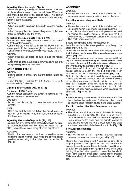
Installing or removing saw blade<br />
CAUTION:<br />
Always be sure that the tool is switched off and<br />
unplugged before installing or removing the blade.<br />
Use only the <strong>Makita</strong> socket wrench provided to install<br />
or remove the blade. Failure to do so may result in<br />
overtightening or insufficient tightening of the hex bolt.<br />
This could cause an injury.<br />
Secure the top table at the topmost position.<br />
Lock the handle in the raised position by pushing in the<br />
stopper pin. (Fig. 14)<br />
To remove the blade, first loosen the clamping screw so<br />
that the lower blade guard B is lowered as shown in the<br />
figure. (Fig. 15)<br />
Then use the socket wrench to loosen the hex bolt holding<br />
the center cover by turning it counterclockwise. Raise<br />
the lower blade guard A and center cover while pushing<br />
the lever nearby the handle to the left. (Fig. 16)<br />
Press the shaft lock to lock the spindle and use the<br />
socket wrench to loosen the hex bolt clockwise. Then<br />
remove the hex bolt, outer flange and blade. (Fig. 17)<br />
To install the blade, mount it carefully onto the spindle,<br />
making sure that the direction of the arrow on the surface<br />
of the blade matches the direction of the arrow on the<br />
blade case. Install the outer flange and hex bolt, and then<br />
use the socket wrench to tighten the hex bolt (lefthanded)<br />
securely counterclockwise while pressing the<br />
shaft lock. (Fig. 18 & 19)<br />
NOTE:<br />
When installing a saw blade, be sure to insert it from<br />
the outside of the blade guard B at first and then raise it<br />
so that the blade is finally placed in the blade guard B.<br />
For all countries other than European countries<br />
CAUTION:<br />
The silver ring 25.4 mm in outer diameter is factoryinstalled<br />
onto the spindle. The black ring 25 mm in<br />
outer diameter is included as standard equipment.<br />
Before mounting the blade onto the spindle, always be<br />
sure that the correct ring for the arbor hole of the blade<br />
you intend to use is installed onto the spindle. (Fig. 20)<br />
For European countries<br />
CAUTION:<br />
The ring 30 mm in outer diameter is factory-installed<br />
between the inner and outer flanges. (Fig. 20)<br />
Return the lower blade guard A and center cover to its<br />
original position. Then tighten the hex bolt clockwise to<br />
secure the center cover. Raise the blade guard B as far<br />
as it will go and tighten the clamping screw firmly while<br />
holding it in the raised position. Lower the handle to<br />
make sure that the lower blade guards move properly.<br />
Make sure shaft lock has released spindle before making<br />
cut.