AIRTRONIC D 2 in MB Sprinter NCV3 (DOKA) / VW Crafter ... - Espar
AIRTRONIC D 2 in MB Sprinter NCV3 (DOKA) / VW Crafter ... - Espar
AIRTRONIC D 2 in MB Sprinter NCV3 (DOKA) / VW Crafter ... - Espar

Erfolgreiche ePaper selbst erstellen
Machen Sie aus Ihren PDF Publikationen ein blätterbares Flipbook mit unserer einzigartigen Google optimierten e-Paper Software.
Informationsblatt zum Werkse<strong>in</strong>bau<br />
Information sheet to work <strong>in</strong>stallation<br />
<br />
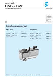
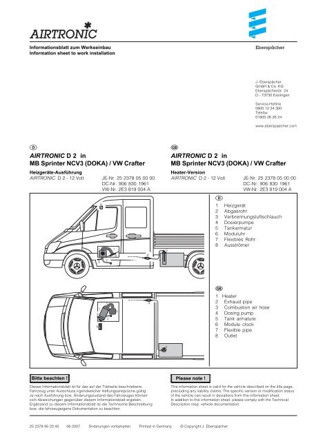
<strong>AIRTRONIC</strong> D 2 <strong>in</strong><br />
<strong>MB</strong> Spr<strong>in</strong>ter <strong>NCV3</strong> (<strong>DOKA</strong>) / <strong>VW</strong> <strong>Crafter</strong><br />
Heizgeräte-Ausführung<br />
<strong>AIRTRONIC</strong> D 2 - 12 Volt JE-Nr. 25 2378 05 00 00<br />
DC-Nr. 906 830 1961<br />
<strong>VW</strong>-Nr. 2E3 819 004 A<br />
Bitte beachten !<br />
Dieses Informationsblatt ist für das auf der Titelseite beschriebene<br />
Fahrzeug unter Ausschluss irgendwelcher Haftungsansprüche gültig.<br />
Je nach Ausführung bzw. Änderungszustand des Fahrzeuges können<br />
sich Abweichungen gegenüber diesem Informationsblatt ergeben.<br />
Ergänzend zu diesem Informationsblatt ist die Technische Beschreibung<br />
bzw. die fahrzeugeigene Dokumentation zu beachten.<br />
3<br />
6<br />
1<br />
3<br />
1<br />
6<br />
2<br />
7<br />
2<br />
7<br />
8<br />
8<br />
25 2378 95 20 45 06.2007 Änderungen vorbehalten Pr<strong>in</strong>ted <strong>in</strong> Germany © Copyright J. Eberspächer<br />
4<br />
4<br />
5<br />
5<br />
Eberspächer<br />
J. Eberspächer<br />
GmbH & Co. KG<br />
Eberspächerstr. 24<br />
D - 73730 Essl<strong>in</strong>gen<br />
Service-Hotl<strong>in</strong>e<br />
0800 12 34 300<br />
Telefax<br />
01805 26 26 24<br />
www.eberspaecher.com<br />
<br />
<strong>AIRTRONIC</strong> D 2 <strong>in</strong><br />
<strong>MB</strong> Spr<strong>in</strong>ter <strong>NCV3</strong> (<strong>DOKA</strong>) / <strong>VW</strong> <strong>Crafter</strong><br />
Heater-Version<br />
<strong>AIRTRONIC</strong> D 2 - 12 Volt JE-Nr. 25 2378 05 00 00<br />
DC-Nr. 906 830 1961<br />
<strong>VW</strong>-Nr. 2E3 819 004 A<br />
<br />
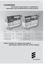
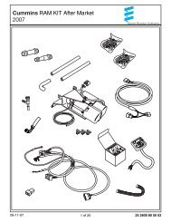
1 Heizgerät<br />
2 Abgasrohr<br />
3 Verbrennungsluftschlauch<br />
4 Dosierpumpe<br />
5 Tankarmatur<br />
6 Moduluhr<br />
7 Flexibles Rohr<br />
8 Ausströmer<br />
Please note !<br />
<br />
1 Heater<br />
2 Exhaust pipe<br />
3 Combustion air hose<br />
4 Dos<strong>in</strong>g pump<br />
5 Tank armature<br />
6 Module clock<br />
7 Flexible pipe<br />
8 Outlet<br />
This <strong>in</strong>formation sheet is valid for the vehicle described on the title page,<br />
preclud<strong>in</strong>g any liability claims. The specific version or modification status<br />
of the vehicle can result <strong>in</strong> deviations from this <strong>in</strong>formation sheet.<br />
In addition to this <strong>in</strong>formation sheet, please comply with the Technical<br />
Description resp. vehicle documentation.
Technische Daten<br />
Heizmedium Luft<br />
Brennstoff Diesel - handelsüblich, EN 590<br />
Regelstufen Power/Groß/Mittel/Kle<strong>in</strong>/Aus<br />
Wärmestrom 2200 / 1600 / 1200 / 850 Watt<br />
Brennstoffverbrauch 0,28 / 0,23 / 0,15 / 0,10 l/h<br />
Nennspannung 12 Volt<br />
Betriebsbereich 10,6 bis 16 Volt<br />
Untere Spannungsgrenze<br />
Ansprechzeit - Unterspannungsschutz: 20 Sek.<br />
E<strong>in</strong> im Steuergerät e<strong>in</strong>gebauter Unterspannungsschutz<br />
schaltet die Heizgeräte bei erreichen der Spannungsgrenze<br />
ab.<br />
Obere Spannungsgrenze<br />
Ansprechzeit - Unterspannungsschutz: 20 Sek.<br />
E<strong>in</strong> im Steuergerät e<strong>in</strong>gebauter Überspannungsschutz<br />
schaltet die Heizgeräte bei erreichen der Spannungsgrenze<br />
ab.<br />
Elektrische Leistungsaufnahme<br />
beim Start < 100 Watt<br />
Betrieb 34 / 23 / 12 / 8 Watt<br />
Regelstufe - Aus 4 Watt<br />
Mediumdurchsatz ohne 105 / 87 / 60 / 42 kg/h<br />
Gegendruck Regelstufe - Aus 13 kg/h<br />
Funkentstörgrad Entstörklasse 5 nach<br />
DIN 55 025<br />
Gewicht ca. 2,7 kg<br />
Lüftungsbetrieb möglich<br />
Heizluftansaugtemperatur max. +40 °C<br />
Umgebungstemperatur<br />
Heizgerät<br />
- im Betrieb -40 °C bis + 70 °C<br />
- ohne Betrieb -40 °C bis + 85 °C<br />
Dosierpumpe<br />
- im Betrieb -40 °C bis + 50 °C<br />
- ohne Betrieb -40 °C bis + 125 °C<br />
Alle Technische Daten ± 10 %<br />
2<br />
<br />
Technical data<br />
Heat<strong>in</strong>g medium air<br />
Fuel commercially available diesel<br />
fuel, EN 590<br />
Control stages power/large/middle/small/off<br />
Thermal current 2200 / 1600 / 1200 / 850 Watt<br />
Fuel consumption 0,28 / 0,23 / 0,15 / 0,10 l/h<br />
Rated voltage 12 V<br />
Operat<strong>in</strong>g range 10.6 to 16 V<br />
Lower voltage limit<br />
Response time – undervoltage protection: 20 sec.<br />
Undervoltage protection fitted <strong>in</strong> the controller switches<br />
the heater off on reach<strong>in</strong>g the voltage limit.<br />
Upper voltage limit:<br />
Response time – overvoltage 1 protection: 20 sec.<br />
Overvoltage protection fitted <strong>in</strong> the controller switches<br />
the heater off on reach<strong>in</strong>g the voltage limit.<br />
Electrical power consumption<br />
at start < 100 Watt<br />
dur<strong>in</strong>g operation 34 / 23 / 12 / 8 Watt<br />
control stage off 4 Watt<br />
Medium flow rate without 105 / 87 / 60 / 42 kg/h<br />
counter pressure control stage off 13 kg/h<br />
Interference suppression Interference class 5 as per<br />
DIN 55 025<br />
Weight approx. 2,7 kg<br />
Ventilation operation possible<br />
Hot air <strong>in</strong>take temperature max. +40 °C<br />
Ambient temperature<br />
Heater<br />
- <strong>in</strong> operation -40 °C to + 70 °C<br />
- not <strong>in</strong> operation -40 °C to + 85 °C<br />
Dos<strong>in</strong>g pump<br />
- <strong>in</strong> operation -40 °C bis + 50 °C<br />
-not <strong>in</strong> operation -40 °C bis + 125 °C<br />
All technical data ± 10 %
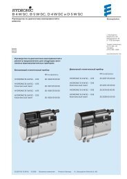
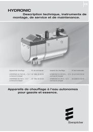
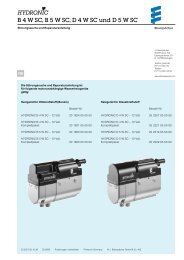
E<strong>in</strong>bauplatz Heizgerät<br />
Das Heizgerät ist <strong>in</strong> der Fahrerkab<strong>in</strong>e, im rechten<br />
Sitzkasten e<strong>in</strong>gebaut.<br />
Das Heizgerät arbeitet im Umluftbetrieb.<br />
Heizgerät e<strong>in</strong>gebaut im Kasten<br />
Heater <strong>in</strong>stalled <strong>in</strong> box<br />
Flex. Schlauch für Heizluftführung<br />
Flexible hose for hot air system<br />
Abgasführung<br />
Das flexible Abgasrohr ist 320 mm lang und zusätzlich mit<br />
e<strong>in</strong>er Befestigungsschelle am Fahrzeugboden befestigt.<br />
Verbrennungsluftführung<br />
Der Verbrennungsluftschlauch ist 160 mm lang und<br />
zusätzlich mit e<strong>in</strong>er Befestigungsschelle am Fahrzeugboden<br />
befestigt.<br />
Bei der Montage muss darauf geachtet werden, dass<br />
ausreichend Abstand zwischen dem Verbrennungsluftschlauch<br />
und fahrzeugseitiger Wandung besteht.<br />
<br />
<br />
3<br />
<br />
Heater <strong>in</strong>stallation position<br />
The heater is fitted <strong>in</strong> the driver’s cab, <strong>in</strong> the right seat box.<br />
The heater works <strong>in</strong> recirculation mode.<br />
<br />
Exhaust gas system<br />
The flexible exhaust pipe is 320 mm long and fastened<br />
additionally to the vehicle floor with a fasten<strong>in</strong>g clip.<br />
Combustion air system<br />
The combustion air hose is 160 mm long and fastened<br />
additionally to the vehicle floor with a fasten<strong>in</strong>g clip.<br />
Dur<strong>in</strong>g <strong>in</strong>stallation, care must be given to ensure that<br />
there is sufficient clearance between the combustion air<br />
hose and the wall of the vehicle.<br />
Flexibles Abgasrohr - entgegen der Fahrtrichtung gerichtet<br />
Flexible exhaust pipe, po<strong>in</strong>t<strong>in</strong>g opposite to the direction of travel<br />
Verbrennungsluftschlauch - <strong>in</strong> Fahrtrichtung gerichtet<br />
Combustion air hose – po<strong>in</strong>t<strong>in</strong>g <strong>in</strong> the direction of travel
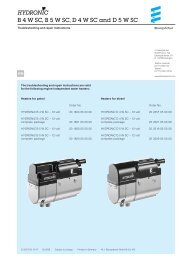
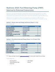
Brennstoffversorgung<br />
Die Dosierpumpe ist mit e<strong>in</strong>er Gummihalterung am l<strong>in</strong>ken<br />
Längsrahmen befestigt.<br />
Die Brennstoffentnahme erfolgt durch e<strong>in</strong> Steigrohr,<br />
e<strong>in</strong>gebaut <strong>in</strong> der Tankarmatur.<br />
Bitte beachten ! Please note !<br />
Bei <strong>NCV3</strong> gibt es zwei Tankvarianten:<br />
1x 75 Litertank (Serie) - Heizgerätebetrieb bis ca. 15 Liter<br />
Tankvolumen möglich<br />
1x 100 Litertank (SA) - Heizgerätebetrieb bis ca. 25 Liter<br />
Tankvolumen möglich<br />
Bei Erreichen dieser o.g. M<strong>in</strong>destmengen geht das<br />
Heizgerät auf Störung -> Fehleranzeige <strong>in</strong> der Moduluhr.<br />
Nach dem Betanken muss das Leitungssystem durch<br />
mehrmaliges E<strong>in</strong>- und Ausschalten über die Moduluhr<br />
(bis zu ca. 4 mal) befüllt und entlüftet werden.<br />
Dieser Vorgang kann ca. 30 M<strong>in</strong>uten betragen, bis die<br />
Heizgerätefunktion wieder gewährleistet ist.<br />
<br />
Dosierpumpe / Dos<strong>in</strong>g pump<br />
4<br />
<br />
Fuel supply<br />
The meter<strong>in</strong>g pump is fastened to the left longitud<strong>in</strong>al<br />
frame with a rubber holder. The fuel is withdrawn through<br />
a ris<strong>in</strong>g pipe, <strong>in</strong>stalled <strong>in</strong> the tank fitt<strong>in</strong>g.<br />
The <strong>NCV3</strong> has two tank versions:<br />
1x 75 l tank (standard): heaters can be operated to a tank<br />
volume of approx. 15 l.<br />
1x 100 l tank (SA): heaters can be operated to a tank<br />
volume of approx. 25 l<br />
On reach<strong>in</strong>g the m<strong>in</strong>imum levels stated above, the heater<br />
<strong>in</strong>dicates a fault with an error display <strong>in</strong> the module timer.<br />
After refuell<strong>in</strong>g, the pipe system must be filled and vented<br />
by switch<strong>in</strong>g on at the module timer several times (up to<br />
approx. 4 times). This can take approx. 30 m<strong>in</strong>utes until<br />
the heater will function properly aga<strong>in</strong>.
Luftführung<br />
Die Umluftansaug erfolgt durch das Gitter, seitlich im<br />
Sitzkasten.<br />
Die Heizluft strömt durch den Ausströmer, e<strong>in</strong>gebaut im<br />
Sitzkasten <strong>in</strong> den Fahrzeug<strong>in</strong>nenraum.<br />
Vom Heizgerät zum Ausströmer ist e<strong>in</strong> flex. Schlauch<br />
verlegt.<br />
Gitter seitlich im Sitzkasten<br />
Grat<strong>in</strong>g on the side <strong>in</strong> the seat box<br />
Bedienelement<br />
Die Moduluhr bef<strong>in</strong>det sich im Fahrzeug<strong>in</strong>nenraum, <strong>in</strong><br />
der Dachkonsole über Innenraumleuchte.<br />
Die Bedienung der Moduluhr ist <strong>in</strong> der fahrzeugeigenen<br />
Dokumentation beschrieben.<br />
Diagnose<br />
Im Fehlerfall kann die Störung mit der Moduluhr<br />
ausgelesen werden.<br />
<strong>MB</strong>-Diagnose ist nicht möglich.<br />
<br />
<br />
Moduluhr / Module timer<br />
5<br />
<br />
Air system<br />
The air is taken <strong>in</strong>to the recirculation system through the<br />
grat<strong>in</strong>g on the side <strong>in</strong> the seat box.<br />
The heater air flows <strong>in</strong>to the vehicle <strong>in</strong>terior through the outlet<br />
<strong>in</strong> the seat box.<br />
A flexible hose is routed from the heater to the outlet.<br />
Ausströmer, e<strong>in</strong>gebaut im Sitzkasten<br />
Outlet, <strong>in</strong>tegrated <strong>in</strong> the seat box<br />
Control element<br />
The module timer is located <strong>in</strong> the vehicle <strong>in</strong>terior, <strong>in</strong> the<br />
overhead console above the <strong>in</strong>terior light.<br />
Operation of the module timer is described <strong>in</strong> the vehicle<br />
documentation.<br />
Diagnosis<br />
In the case of an error, the fault can be read out with the<br />
module timer.<br />
<strong>MB</strong> diagnosis is not possible.
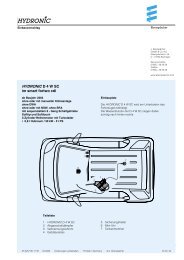
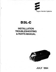
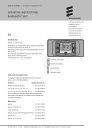
Schaltplan<br />
Circuit diagram<br />
Flachsteckergehäuse 12 pol. AMP<br />
<strong>MB</strong> Nr. 026 545 96 28<br />
Gegenstecker dazu passend:<br />
Steckhülsengehäuse 12 pol. AMP<br />
<strong>MB</strong> Nr. 005 545 94 26<br />
Flat receptacle hous<strong>in</strong>g 12-p<strong>in</strong> AMP<br />
<strong>MB</strong> No. 026 545 96 28<br />
Match<strong>in</strong>g mat<strong>in</strong>g plug:<br />
Receptacle hous<strong>in</strong>g 12-p<strong>in</strong> AMP<br />
<strong>MB</strong> No. 005 545 94 26<br />
Steckhülsengehäuse 2 pol.<br />
AMP 0-282 189-1<br />
Receptacle hous<strong>in</strong>g 2-p<strong>in</strong><br />
AMP 0-282 189-1<br />
6<br />
Steckhülsengehäuse 12 pol. AMP<br />
<strong>MB</strong> Nr. 005 545 94 26<br />
Receptacle hous<strong>in</strong>g 12-p<strong>in</strong> AMP<br />
<strong>MB</strong> No. 005 545 94 26<br />
25 2378 00 96 01 A
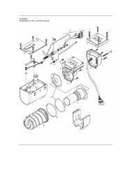
Teileliste<br />
1.1 Brennermotor<br />
1.2 Glühstift<br />
1.5 Überhitzungsfühler / Flammfühler<br />
2.1 Steuergerät<br />
2.2 Dosierpumpe<br />
2.7 Hauptsicherung, 20 A<br />
2.7.1 Sicherung - Betätigung, 5 A<br />
3.2.8 Moduluhr<br />
5.1 Batterie<br />
a) Diebstahlwarnanlage<br />
b) <strong>MB</strong> Diagnose (nicht angeschlossen)<br />
d) bei Nichtbelegung Kammer 4 (3.2.8) ADR-Funktion<br />
e) JE Diagnose<br />
Stecker - und Buchsengehäuse s<strong>in</strong>d von der<br />
Leitungse<strong>in</strong>trittseite dargestellt<br />
sw = schwarz<br />
br = braun<br />
rt = rot<br />
ge = gelb<br />
gn = grün<br />
bl = blau<br />
gr = grau<br />
ws = weiß<br />
7<br />
<br />
Parts list<br />
1.1 Burner eng<strong>in</strong>e<br />
1.2 Glow plug<br />
1.5 Overheat<strong>in</strong>g sensor / Flame sensor<br />
2.1 Controller<br />
2.2 Dos<strong>in</strong>g pump<br />
2.7 Ma<strong>in</strong> fuse, 20 A<br />
2.7.1 Fuse, actuation, 5 A<br />
3.2.8 Module timer<br />
5.1 Battery<br />
a) Vehicle alarm<br />
b) <strong>MB</strong> diagnosis (not connected)<br />
d) when not <strong>in</strong> use: chamber 4 (3.2.8) ADR function<br />
e) JE diagnosis<br />
Connectors and bush hous<strong>in</strong>gs are shown from<br />
the cable <strong>in</strong>let side<br />
sw = black<br />
br = brown<br />
rt = red<br />
ge = yellow<br />
gn = green<br />
bl = blue<br />
gr = grey<br />
ws = white
Ersatzteile<br />
Abweichende Ersatzteile zum Basis-Heizgerät mit der<br />
Ausführungs-Nr. 25 2069 05 00 00.<br />
Benennung Bestell Nr.<br />
Steuergerät 22 5101 00 34 02<br />
DC Bestell Nr. 001 446 18 29<br />
<strong>VW</strong> Bestell Nr. 2E0 909 516 A<br />
Dosierpumpe 22 4519 03 00 0 0<br />
DC Bestell Nr. 001 835 07 02<br />
<strong>VW</strong> Bestell Nr. 2E1 819 029 B<br />
Schlauch, 75 mm 25 2378 80 00 01<br />
DC Bestell Nr. 906 997 04 52<br />
<strong>VW</strong> Bestell Nr. 2E1 883 913<br />
Schlauch, 75 mm 25 2378 80 00 02<br />
DC Bestell Nr. 906 997 05 52<br />
<strong>VW</strong> Bestell Nr. 2E1 883 913 A<br />
Abgasrohr, 24 mm 25 2378 80 04 00<br />
DC Bestell Nr. 906 830 45 15<br />
<strong>VW</strong> Bestell Nr. 2E3 819 085<br />
Kraftstoffleitung 25 2378 80 05 00<br />
DC Bestell Nr. 906 832 01 64<br />
<strong>VW</strong> Bestell Nr. 2E1 819 887<br />
Verbrennungsluftschlauch 25 2378 80 02 00<br />
DC Bestell Nr. 906 997 09 52<br />
<strong>VW</strong> Bestell Nr. 2E1 983 913 B<br />
Ausströmer 25 2378 80 00 03<br />
DC Bestell Nr. 906 835 00 18<br />
<strong>VW</strong> Bestell Nr. 2E1 819 383<br />
Weitere Ersatzteile können aus der Ersatzteilliste mit<br />
der Druck Nr. 25 2069 95 12 06, Ausgabe 11. 2005<br />
ausgewählt werden.<br />
8<br />
<br />
Spare parts<br />
Deviat<strong>in</strong>g spare parts from the basic heater version<br />
number 25 2069 05 00 00.<br />
Name Order number<br />
Control box 22 5101 00 34 02<br />
DC order number 001 446 18 29<br />
<strong>VW</strong> order number 2E0 909 516 A<br />
Meter<strong>in</strong>g pump 22 4519 03 00 0 0<br />
DC order number 001 835 07 02<br />
<strong>VW</strong> order number 2E1 819 029 B<br />
Hose, 75 mm 25 2378 80 00 01<br />
DC order number 906 997 04 52<br />
<strong>VW</strong> order number 2E1 883 913<br />
Hose, 75 mm 25 2378 80 00 02<br />
DC order number 906 997 05 52<br />
<strong>VW</strong> order number 2E1 883 913 A<br />
Exhaust pipe, 24 mm 25 2378 80 04 00<br />
DC order number 906 830 45 15<br />
<strong>VW</strong> order number 2E3 819 085<br />
Fuel pipe 25 2378 80 05 00<br />
DC order number 906 832 01 64<br />
<strong>VW</strong> order number 2E1 819 887<br />
Combustion air hose 25 2378 80 02 00<br />
DC order number 906 997 09 52<br />
<strong>VW</strong> order number 2E1 983 913 B<br />
Outlet 25 2378 80 00 03<br />
DC order number 906 835 00 18<br />
<strong>VW</strong> order number 2E1 819 383<br />
Other spare parts can be chosen from the spare parts list<br />
pr<strong>in</strong>t number 25 2069 95 12 06, issue 11.2005.