HYDRONIC D 5 W S in Mercedes Benz - Sprinter, T1N, NAFTA - Espar
HYDRONIC D 5 W S in Mercedes Benz - Sprinter, T1N, NAFTA - Espar
HYDRONIC D 5 W S in Mercedes Benz - Sprinter, T1N, NAFTA - Espar

Sie wollen auch ein ePaper? Erhöhen Sie die Reichweite Ihrer Titel.
YUMPU macht aus Druck-PDFs automatisch weboptimierte ePaper, die Google liebt.
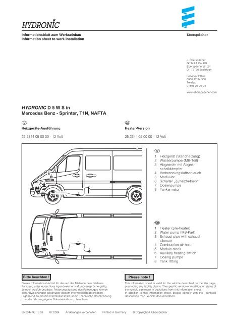
Informationsblatt zum Werkse<strong>in</strong>bau<br />
Information sheet to work <strong>in</strong>stallation<br />
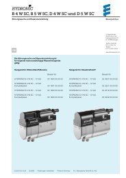
<strong>HYDRONIC</strong> D 5 W S <strong>in</strong><br />
<strong>Mercedes</strong> <strong>Benz</strong> - Spr<strong>in</strong>ter, <strong>T1N</strong>, <strong>NAFTA</strong><br />
<br />
Heizgeräte-Ausführung<br />
25 2344 05 00 00 - 12 Volt<br />
Bitte beachten !<br />
Dieses Informationsblatt ist für das auf der Titelseite beschriebene<br />
Fahrzeug unter Ausschluss irgendwelcher Haftungsansprüche gültig.<br />
Je nach Ausführung bzw. Änderungszustand des Fahrzeuges können<br />
sich Abweichungen gegenüber diesem Informationsblatt ergeben.<br />
Ergänzend zu diesem Informationsblatt ist die Technische Beschreibung<br />
bzw. die fahrzeugeigene Dokumentation zu beachten.<br />
<br />
Heater-Version<br />
25 2344 05 00 00 - 12 Volt<br />
Please note !<br />
25 2344 95 16 59 07.2004 Änderungen vorbehalten Pr<strong>in</strong>ted <strong>in</strong> Germany © Copyright J. Eberspächer<br />
Eberspächer<br />
J. Eberspächer<br />
GmbH & Co. KG<br />
Eberspächerstr. 24<br />
D - 73730 Essl<strong>in</strong>gen<br />
Service-Hotl<strong>in</strong>e<br />
0800 12 34 300<br />
Telefax<br />
01805 26 26 24<br />
www.eberspaecher.com<br />
<br />
1 Heizgerät (Standheizung)<br />
2 Wasserpumpe (MB-Teil)<br />
3 Abgasrohr mit Abgasschalldämpfer<br />
4 Verbrennungsluftschlauch<br />
5 Moduluhr<br />
6 Schalter „Zuheizbetrieb“<br />
7 Dosierpumpe<br />
8 Tankarmatur<br />
<br />
1 Heater (pre-heater)<br />
2 Water pump (MB-Part)<br />
3 Exhaust pipe with exhaust<br />
silencer<br />
4 Combustion air hose<br />
5 Module clock<br />
6 Auxiliary heat<strong>in</strong>g switch<br />
7 Dos<strong>in</strong>g pumpe<br />
8 Tank fitt<strong>in</strong>g<br />
This <strong>in</strong>formation sheet is valid for the vehicle described on the title page,<br />
preclud<strong>in</strong>g any liability claims. The specific version or modification status of<br />
the vehicle can result <strong>in</strong> deviations from this <strong>in</strong>formation sheet.<br />
In addition to this <strong>in</strong>formation sheet, please comply with the Technical<br />
Description resp. vehicle documentation.
Technische Daten<br />
Heizmedium Wasser-Glykol-Gemische<br />
Brennstoff Diesel - handelsüblich, EN 590<br />
Regelstufen Groß / Kle<strong>in</strong><br />
Wärmestrom Groß - 5000 Watt<br />
Kle<strong>in</strong> - 2400 Watt<br />
Brennstoffverbrauch Groß - 0,62 l/h<br />
Kle<strong>in</strong> - 0,30 l/h<br />
Nennspannung 12 Volt<br />
Betriebsbereich 10,2 bis 16 Volt<br />
Untere Spannungsgrenze<br />
Ansprechzeit - Unterspannungsschutz: 20 Sek.<br />
E<strong>in</strong> im Steuergerät e<strong>in</strong>gebauter Unterspannungsschutz<br />
schaltet die Heizgeräte bei erreichen der Spannungsgrenze<br />
ab.<br />
Obere Spannungsgrenze<br />
Ansprechzeit - Überspannungsschutz: 20 Sek.<br />
E<strong>in</strong> im Steuergerät e<strong>in</strong>gebauter Überspannungsschutz<br />
schaltet die Heizgeräte bei erreichen der Spannungsgrenze<br />
ab.<br />
Elektrische Leistungsaufnahme<br />
beim Start < 100 Watt<br />
Betrieb Groß 44 Watt<br />
Kle<strong>in</strong> 13 Watt<br />
Zulässiger Betriebsdruck bis 2,5 bar Überdruck<br />
M<strong>in</strong>destwasserdurchsatz 300 l/h<br />
Funkentstörgrad 5 UKW / 5 KW / 5 MW / 2 LW<br />
nach DIN 57 879<br />
Teil 1 VDE 0879<br />
Gewicht ca. 2,3 kg<br />
Umgebungstemperatur<br />
Heizgerät<br />
- im Betrieb -40 °C bis + 80 °C<br />
- ohne Betrieb -40 °C bis + 105 °C<br />
Steuergerät<br />
- im Betrieb -40 °C bis + 80 °C<br />
- ohne Betrieb -40 °C bis + 105 °C<br />
Dosierpumpe<br />
- im Betrieb -40 °C bis + 80 °C<br />
- ohne Betrieb -40 °C bis + 105 °C<br />
Alle Technische Daten ± 10 %<br />
2<br />
Technical data<br />
Heat<strong>in</strong>g medium water/glycol mixture<br />
Fuel commercially available diesel<br />
fuel, EN 590<br />
Control stages large / small<br />
Thermal current large - 5000 watt<br />
small - 2400 watt<br />
Fuel consumption large - 0.62 l/h<br />
small - 0.30 l/h<br />
Rated voltage 12 Volt<br />
Operat<strong>in</strong>g range 10.2 to 16 V<br />
Lower voltage limit<br />
Response time – undervoltage protection: 20 sec.<br />
Undervoltage protection fitted <strong>in</strong> the controller switches<br />
the heater off on reach<strong>in</strong>g the voltage limit.<br />
Upper voltage limit:<br />
Response time – overvoltage protection: 20 sec.<br />
Overvoltage protection fitted <strong>in</strong> the controller switches<br />
the heater off on reach<strong>in</strong>g the voltage limit.<br />
Electrical power consumption<br />
at start < 100 watt<br />
dur<strong>in</strong>g operation large 44 watt<br />
small 13 watt<br />
Tolerable operat<strong>in</strong>g up to 2.5 bar overpressure<br />
pressure<br />
M<strong>in</strong>imum water flow 300 l/h<br />
Interference suppression 5 FM / 6 AM / 5 MW / 2 LW<br />
as per DIN 57 879<br />
Part 1 VDE 0879<br />
Weight: approx approx. 2.3 kg<br />
Ambient temperature<br />
Heater<br />
<strong>in</strong> operation -40°C to +80°C<br />
not <strong>in</strong> operation -40°C to +105°C<br />
Controller<br />
<strong>in</strong> operation -40°C to +80°C<br />
not <strong>in</strong> operation -40°C to +105°C<br />
Dos<strong>in</strong>g pump<br />
<strong>in</strong> operation -40°C to +80°C<br />
not <strong>in</strong> operatioN -40°C to +105°C<br />
Alle Technische Daten ± 10 %
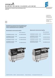
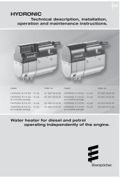
E<strong>in</strong>bauplatz Heizgerät<br />
Das Heizgerät ist unter dem l<strong>in</strong>ken Hauptsche<strong>in</strong>werfer<br />
e<strong>in</strong>gebaut.<br />
Abgasführung<br />
Der Abgasschalldämpfer ist am Längsrahmen befestigt.<br />
Das Abgasrohr ist vom Heizgerät durch e<strong>in</strong>e Bohrung im<br />
Radhaus zum Abgasschalldämpfer verlegt.<br />
Verbrennungsluftführung<br />
Der Verbrennungsluftschlauch ist unter den Batteriekasten<br />
verlegt.<br />
Heizgerät <br />
Verbrennungsluftschlauch <br />
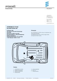
Brennstoffversorgung<br />
Die Dosierpumpe ist auf der l<strong>in</strong>ken Fahrzeugseite<br />
zwischen Fahrzeugtank und Getriebe, neben der<br />
Kardanwelle am Fahrzeugboden befestigt.<br />
Die Brennstoffentnahme erfolgt durch e<strong>in</strong> Steigrohr,<br />
e<strong>in</strong>gebaut <strong>in</strong> der Tankarmatur.<br />
Dosierpumpe <br />
Druckleitung <br />
<br />
<br />
3<br />
<br />
Installation position of heater<br />
The heater is <strong>in</strong>stalled under the left ma<strong>in</strong> headlamp<br />
Exhaust system<br />
The exhaust silencer is fastened to the longitud<strong>in</strong>al frame.<br />
The exhaust pipe from the heater is routed to the exhaust<br />
silencer through a bore <strong>in</strong> the wheel case.<br />
Combustion air system<br />
The combustion air hose is routed under the battery case.<br />
Fuel system<br />
Heater<br />
Combustion air hose<br />
The dos<strong>in</strong>g pump is fastened on the left side of the vehicle on<br />
the floor, between the tank and the gear, next to the universal<br />
shaft.<br />
The fuel is withdrawn through a ris<strong>in</strong>g pipe <strong>in</strong>tegrated <strong>in</strong> the<br />
tank fitt<strong>in</strong>g.<br />
<br />
<br />
Dos<strong>in</strong>g pump<br />
Pressure l<strong>in</strong>e
Bedienelement<br />
Schalter „Zuheizbetrieb“<br />
Der Schalter „Zuheizbetrieb“ bef<strong>in</strong>det sich im Mittelteil<br />
des Armaturenbrettes.<br />
E<strong>in</strong>schalten<br />
Schalter drücken, die Kontrollleuchte im Schalter leuchtet<br />
auf.<br />
Ausschalten<br />
Schalter erneut oben drücken, die Kontrollleuchte<br />
im Schalter erlischt.<br />
Moduluhr<br />
Die Moduluhr ist im Mittelteil des Armaturenbrettes<br />
e<strong>in</strong>gebaut.<br />
Bitte beachten !<br />
Im Zuheizbetrieb schaltet das Heizgerät nach<br />
ca. 120 M<strong>in</strong>uten oder beim Abstellen des Motors<br />
automatisch aus.<br />
Diagnose<br />
Schalter „Zuheizbetrieb“ <br />
Moduluhr <br />
Im Fehlerfall kann die Störung mit dem JE-Diagnosegerät,<br />
dem Kundendienst-Programm KD 2000 oder mit der<br />
DC-Star-Diagnose ausgelesen werden.<br />
Die MB-Diagnosedose darf für das JE-Diagnosegerät<br />
nicht benutzt werden (mehrere Steuergeräte s<strong>in</strong>d mit<br />
dieser Leitung verbunden).<br />
Die Laufzeit des Heizgerätes ist durch e<strong>in</strong> spezifisches<br />
MB-Steuergeräteprogramm auf 120 M<strong>in</strong>uten begrenzt.<br />
Beim Abstellen des Fahrzeugmotors schaltet sich das<br />
Heizgerät automatisch aus.<br />
Die Wasserpumpe ist e<strong>in</strong> MB-Teil.<br />
<br />
4<br />
<br />
Control element<br />
Auxiliary heater switch<br />
The auxiliary heater switch is <strong>in</strong> the middle of the<br />
dashboard.<br />
Switch on<br />
Press the switch: the control light <strong>in</strong> the switch lights up.<br />
Switch off<br />
Press the switch aga<strong>in</strong>: the control light <strong>in</strong> the switch<br />
goes off.<br />
Module timer<br />
The module timer is fitted <strong>in</strong> the middle of the dashboard.<br />
Please note!<br />
In auxiliary heater mode, the heater switches off<br />
automatically after approx. 120 m<strong>in</strong>utes or when the<br />
eng<strong>in</strong>e is turned off.<br />
<br />
Diagnosis<br />
Auxiliary heater switch<br />
Module timer<br />
When a fault occurs, the error can be read out with the<br />
JE diagnosis, the customer service program KD 2000 or the<br />
DC Star diagnosis.<br />
The MB diagnosis socket must not be used for the JE<br />
diagnosis unit (several controllers are connected to this<br />
l<strong>in</strong>e).<br />
The service period of the heater is limited to 120 m<strong>in</strong>s by a<br />
specific MB controller program.<br />
When the vehicle eng<strong>in</strong>e is turned off, the heater switches<br />
off automatically.<br />
The water pump is a MB part.
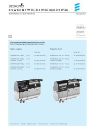
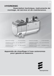
Wasserkreislauf<br />
Das Heizgerät ist <strong>in</strong> der Vorlaufleitung vom<br />
Fahrzeugmotor zum Fahrzeugwärmetauscher<br />
e<strong>in</strong>gesetzt.<br />
Die Wasserpumpe ist e<strong>in</strong> MB - Teil.<br />
In die Wasserleitung zum Fahrzeugmotor ist e<strong>in</strong><br />
Absperrventil bzw. e<strong>in</strong> Taktventil e<strong>in</strong>gesetzt.<br />
Heizgerät<br />
Wasserpumpe (MB-Teil)<br />
Fahrzeugwärmetauscher<br />
Fahrzeugmotor<br />
Absperrventil<br />
Bypass-Durchfluß nur bei geschlossenen Absperrventil<br />
<br />
Steckerbelegung<br />
Kabelstrang-Heizgerät<br />
Kammer Querschnitt/Farbe Funktion Gegenstecker<br />
1 1,5 rt Plus Versorgung, Kl. +30<br />
2 1,5 br M<strong>in</strong>us Versorgung, Kl. -31<br />
3 0,5 sw/rt Plus-Signal, Gebläseansteuerung<br />
4 0,5 gn Plus-Signal, Dosierpumpenansteuerung<br />
5 0,5 bl/ws Diagnose<br />
6 0,5 bl Plus-E<strong>in</strong>schaltsignal,<br />
Zuheizkriterium<br />
7 0,5 ge Plus-E<strong>in</strong>schaltsignal, Uhr<br />
8 0,5 sw/ws nicht belegt<br />
Steckerbelegung<br />
Kabelstrang-Wasserpumpe<br />
Kammer Querschnitt/Farbe Funktion Gegenstecker<br />
A 0,75 br Wasserpumpe, M<strong>in</strong>us<br />
B 0,75 vi Wasserpumpe, Plus<br />
4<br />
5<br />
5<br />
<br />
Water circuit<br />
The heater is <strong>in</strong>tegrated <strong>in</strong> the feed l<strong>in</strong>e from the vehicle<br />
eng<strong>in</strong>e to the vehicle heat exchanger.<br />
The water pump is an MB part.<br />
A shut-off valve or cycle valve is fitted <strong>in</strong> the water pipe to the<br />
vehicle eng<strong>in</strong>e.<br />
2<br />
3<br />
1<br />
Heater<br />
Water pump (MB part)<br />
Vehicle heat exchanger<br />
Vehicle eng<strong>in</strong>e<br />
Shut-off valve<br />
Bypass flow only when shut-off valve closed<br />
<br />
P<strong>in</strong> configuration<br />
Cable harness – heater<br />
Chamber Cross section Function counter connector<br />
colour<br />
1 1,5 red plus supply, term<strong>in</strong>al +30<br />
2 1,5 brown m<strong>in</strong>us supply, term<strong>in</strong>al –31<br />
3 0,5 black/red plus signal, fan control<br />
4 0,5 green plus signal, dos<strong>in</strong>g pump<br />
control<br />
5 0,5 blue/white diagnosis<br />
6 0,5 blue plus switch-on signal,<br />
auxiliary heater criterion<br />
7 0,5 yellow plus switch-on signal, timer<br />
8 0,5 black/white not <strong>in</strong> use<br />
P<strong>in</strong> configuration<br />
Cable hardness – water pump<br />
Chamber Cross section Function counter connector<br />
colour<br />
A 0,75 brown water pump, m<strong>in</strong>us<br />
B 0,75 violet water pump, plus
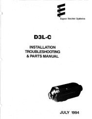
Schaltplan<br />
Wir<strong>in</strong>g diagramm<br />
S1<br />
Flat contact hous<strong>in</strong>g<br />
8-pole Dautz & Rietz<br />
3A0 973 734 – VW<br />
B1<br />
Flat contact hous<strong>in</strong>g<br />
8-pole Dautz & Rietz<br />
3A0 973 734 – VW<br />
6<br />
Inputs Output signals<br />
A B Burner W-pump Fan Remarks<br />
open open OFF OFF OFF<br />
D+ open ON ON OFF auxiliary heater mode<br />
open term<strong>in</strong>al 30 ON ON ON pre-heater mode<br />
D+ term<strong>in</strong>al 30 ON ON ON/OFF pre-heater mode / then<br />
auxiliary heater mode<br />
B2<br />
Receptacle hous<strong>in</strong>g<br />
2-pole Ak 7205<br />
Re<strong>in</strong>shagen<br />
S2<br />
Connector hous<strong>in</strong>g<br />
2-pole Ak 7205<br />
Re<strong>in</strong>shagen<br />
B3<br />
Receptacle hous<strong>in</strong>g<br />
2-pole<br />
0-282 189-A AMP<br />
B4<br />
Receptacle hous<strong>in</strong>g<br />
12-pole AMP<br />
DC No. 005 545 94 26
A/C switch<br />
Term<strong>in</strong>al 30<br />
Special extra “A/C”<br />
Fan stage 1<br />
Special extra “comfort”<br />
Auxiliary heater switch<br />
Term<strong>in</strong>al 31<br />
25 2091 00 96 01<br />
7<br />
Pre-heater switch<br />
Term<strong>in</strong>al 31<br />
Term<strong>in</strong>al 30<br />
Teileliste<br />
1.1 Brennermotor<br />
1.2 Glühstift<br />
1.5 Überhitzungsfühler<br />
1.12 Flammfühler<br />
1.13 Temperaturfühler<br />
2.1 Steuergerät<br />
2.2 Dosierpumpe<br />
2.12 Wasserpumpe<br />
3.2.9 Moduluhr<br />
(Sonderausstattung)<br />
Stecker - und Buchsengehäuse<br />
s<strong>in</strong>d von der Leitungse<strong>in</strong>trittseite<br />
dargestellt<br />
sw = schwarz<br />
br = braun<br />
rt = rot<br />
ge = gelb<br />
gn = grün<br />
bl = blau<br />
gr = grau<br />
ws = weiß<br />
Parts list<br />
1.1 Burner eng<strong>in</strong>e<br />
1.2 Glow plug<br />
1.5 Overheat<strong>in</strong>g sensor<br />
1.12 Flame sensor<br />
1.13 Temperature sensor<br />
2.1 Controller<br />
2.2 Dos<strong>in</strong>g pump<br />
2.12 Water pump<br />
3.2.9 Module timer<br />
(special extra)<br />
Connectors and bush hous<strong>in</strong>gs<br />
are shown from the cable <strong>in</strong>let<br />
side<br />
sw = black<br />
br = brown<br />
rt = red<br />
ge = yellow<br />
gn = green<br />
bl = glue<br />
gr = grey<br />
ws = white
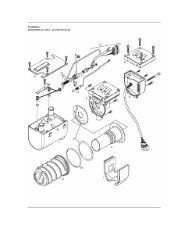
Ersatzteile<br />
Spare parts<br />
8
Bild-Nr. Stückzahl Benennung Bestell-Nr. JE Bestell-Nr. MB<br />
<br />
Fig. No Quantity Designation JE order number MB order number<br />
1 1 Mantel 25 1922 01 01 01 001 830 09 03<br />
Jacket<br />
2 1 Gebläse, Verbrennungsluft 25 221915 00 00 000 835 52 07<br />
Fan, combustion air<br />
3 1 Brennkammer mit Flammrohr 25 2216 10 00 00 000 831 13 85<br />
Combustion chamber with flame tube<br />
4 1 Wärmetauscher 25 2149 06 00 01 003 835 71 01<br />
Heat exchanger<br />
5 1 Steuergerät 22 5201 00 50 03 001 446 03 29<br />
Controller<br />
6 1 Deckel 25 1922 01 00 02 000 835 00 56<br />
Cover<br />
7 1 Dichtungen 20 1820 99 00 01 001 835 42 98<br />
Gaskets<br />
8 1 O-R<strong>in</strong>g, 74 x 3 22 1000 70 00 02 001 835 42 98<br />
O-r<strong>in</strong>g, 74 x 3<br />
9 1 Glühstift 25 2106 01 10 00 000 835 40 26<br />
Glow plug<br />
10 1 Fühler, Flammüberwachung 25 1920 35 00 00 000 830 89 72<br />
Sensor, flame monitor<strong>in</strong>g<br />
11 1 Leitungsstrang 25 2149 01 20 00 000 820 21 13<br />
Cable harness<br />
12 1 Druckfeder 25 1922 01 00 05 000 993 65 05<br />
Pressure spr<strong>in</strong>g<br />
13 2 O-R<strong>in</strong>g, 7,5 x 2 320 75 159 014 997 26 45<br />
O-r<strong>in</strong>g, 7.5 x 2<br />
14 1 Abdeckung 20 1864 01 00 03 000 835 16 09<br />
Cover<br />
15 1 Dosierpumpe 22 4503 00 00 00 000 478 22 01<br />
Dos<strong>in</strong>g pump<br />
16 1 Topfsieb 25 1312 00 00 06 000 473 00 35<br />
Cup filter<br />
17 1 Schalldämpfer, Abgas, vormontiert 25 2091 80 01 00 000 830 14 24<br />
Silencer, exhaust, pre-mounted<br />
9