Einbauanleitung
Einbauanleitung
Einbauanleitung

Sie wollen auch ein ePaper? Erhöhen Sie die Reichweite Ihrer Titel.
YUMPU macht aus Druck-PDFs automatisch weboptimierte ePaper, die Google liebt.
© COPYRIGHT 2012 DEHN + SÖHNE / protected by ISO 16016<br />
Montageanleitung<br />
Fangstangenhalter für Steildächer<br />
zur Aufnahme:<br />
- von Fangstangen mit ∅ 16/10 mm<br />
- von Fangstangen GFK/AI mit ∅ 16/10 mm<br />
- von Fangspitzen mit ∅ 10 mm<br />
Überspannungsschutz<br />
Blitzschutz / Erdung<br />
Arbeitsschutz<br />
DEHN + SÖHNE<br />
GmbH + Co. KG<br />
Postfach 1640<br />
92306 Neumarkt<br />
Tel. +49 9181 906-0<br />
Fax +49 9181 906-1100<br />
www.dehn.de<br />
info@dehn.de<br />
Blitzschutz / Erdung<br />
Publication No. 1796 DE / UPDATE 06.12 Id No. 064234
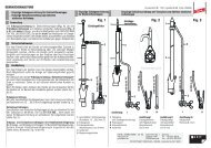
1. Anwendung / Aufbau<br />
Der Fangstangenhalter dient zur Aufnahme einer Fangstange/Fangspitze oder einer<br />
GFK/AI-Fangstange mit einem Durchmesser von 16/10 mm. Angewendet wird das System für<br />
getrennte Fangeinrichtung von Sende-/Empfangsanlagen (Parabol-, terrestrische Antennen) oder z.B.<br />
für PV-, solarthermische Anlagen auf Steildächern. Im Auslieferungszustand ist der Fangstangenhalter<br />
lose beigepackt (siehe Bild 1).<br />
2 x Holzschraube,<br />
(Torx T40, 8 x120/80)<br />
2 x Federscheibe<br />
2 x Überleger<br />
Bild 1<br />
Auslieferungszustand, Fangstangenhalter<br />
2. Montage / Fangstangenhalter<br />
2<br />
Aufnahmebuchse<br />
D= 16/16/10 mm<br />
Strebe D=16 mm<br />
M10 x 16 mm<br />
M10 x 16 mm<br />
M10 x 16 mm<br />
Der Fangstangenhalter kann nur auf geeignete, tragfähige Unterkonstruktionen montiert werden.<br />
Für die Montage ist eine Konterlattung zwingend erforderlich.<br />
Der Fangstangenhalter ist für ein eingeleitetes Moment bis 35 Nm konzipiert. Dieses Moment wirkt<br />
entsprechend auf die Unterkonstruktion. Der Fangstangenhalter kann nicht bei<br />
Biberschwanz-Dachziegel eingesetzt werden.<br />
Zur Montage des Fangstangenhalters werden nachfolgende Werkzeuge benötigt:<br />
- Akku-Schrauber<br />
- Holzbohrer ∅ 5 mm<br />
- Bit-Einsatz, Torx T40<br />
- Gabel-/ Ringschlüssel, SW 17<br />
- Wasserwaage<br />
- Zollstock
- ggf. Winkelschleifer<br />
- ggf. Drahtbürste<br />
- Lappen (zum Reinigen der Klebeflächen)<br />
In der nachfolgenden Bildfolge werden die einzelnen Montageschritte aufgezeigt:<br />
Vor der Montage der Fangstangen/Fangspitze muss der Fangstangenhalter auf das jeweilige Steildach<br />
montiert werden. Für die Montage des Fangstangenhalters ist eine Konterlattung auf den Dachsparren<br />
zwingend erforderlich (siehe Bild 2).<br />
Der Fangstangenhalter kann bei Steildächern mit einer Dachneigung von 24° bis 53° Grad eingesetzt<br />
werden. Die Abstände der Konterlattung können von 60 -75 mm variieren. Die Abstände der Dachsparren<br />
können dabei von 50 bis 70 cm variieren (siehe Bild 2).<br />
Dachsparren<br />
Konterlattung<br />
Bild 2<br />
Fangstangenhalter<br />
Dachsparrenabstand<br />
Konterlattungsabstand<br />
3
Montageschritt<br />
1<br />
Zuerst wird der Fangstangenhalter (Strebe mit Aufnahmebuchse) auf die beiden Konterlattungen<br />
aufgesetzt. Die Platzierung hat so zu erfolgen, dass sich der Fangstangenhalter (Aufnahmebuchse)<br />
genau in der Mitte eines entfernten Dachziegel befindet. Die richtige Platzierung horizontal und vertikal<br />
ist besonders wichtig, da später über die Aufnahmebuchse mit Fangstange der ALU-Dachziegel passen<br />
muss (siehe Bild 3).<br />
Dachsparren<br />
Konterlattung<br />
Bild 3<br />
Fangstangenhalter<br />
Fangstangenhalter<br />
Position des<br />
entfernten Dachziegels<br />
links<br />
Aufnahmebuchse<br />
Dachsparrenabstand<br />
Konterlattungsabstand<br />
4<br />
rechts
Montageschritt<br />
Nach genauer Platzierung wird der Fangstangenhalter mit den im Lieferumfang enthalten Holzschrauben,<br />
Federscheiben, und Überleger festgeschraubt:<br />
2 Stück, Holzschrauben<br />
2 Stück, Federscheibe<br />
2 Stück, Überleger<br />
Hinweis:<br />
Es empfiehlt sich die Konterlattung vorzubohren (Holzbohrer ca. Ø 5 mm) , damit beim Festschrauben<br />
des Fangstangenhalters keine Beschädigungen (Risse, Brüche) an der Konterlattung entstehen<br />
(siehe Bild 4).<br />
Bild<br />
4<br />
2<br />
3<br />
2<br />
1<br />
2<br />
Bohrung Ø 5 mm<br />
3<br />
1<br />
1<br />
2<br />
3<br />
Bohrung Ø 5 mm<br />
Dachsparrenabstand<br />
Konterlattungsabstand<br />
5
Zur horizontalen Ausrichtung kann die Aufnahmebuchse je nach Bedarf nach links oder rechts<br />
verschoben werden. Nach genauer Platzierung wird nun die untere Arretierungsschraube M10 x 16 mm<br />
leicht angeschraubt. Die Aufnahmebuchse muss sich auf jedem Fall in der Mitte des darunter und darüber<br />
liegenden Dachziegels befinden (siehe Bild 5).<br />
Aufnahmebuchse<br />
25 Nm<br />
Bild 5<br />
Fangstangenhalter<br />
Arretierungsschraube<br />
M10 x 16 mm<br />
Arretierungsschraube<br />
M10 x 16 mm<br />
untere Arretierungsschraube<br />
M10 x 16 mm<br />
links<br />
rechts<br />
Aufnahmebuchse<br />
6
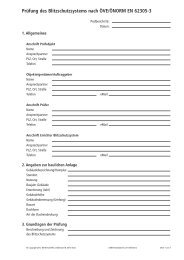
3. Anschluss / Montage der Fangstangen<br />
Mit dem Fangstangenhalter können verschiedene Aufbauvarianten realisiert werden (siehe Bild 6).<br />
Die Fangstangen aus Metall bis zu einer max. Länge von 1,5 m (16/10 mm) und die Fangstangen GFK/AI<br />
sind für eine Windgeschwindigkeit bis 145 km/h (Windlastzone II) einsetzbar (siehe Bild 6).<br />
Fangspitzen, Ø 10 mm, L=1000 mm<br />
(Material aus: Alu, Kupfer, NIRO)<br />
Bild<br />
Fig. 1<br />
6<br />
Fangstangen, Ø 16/10 mm, max. L=1500 mm<br />
(Material aus: Alu, Kupfer, Stahl/tZn,NIRO<br />
(auch Rohrfangstangen)<br />
Fangstangen aus GFK/Alu, Ø 16 /10 mm, Baukastenprogramm mit Fangspitze<br />
Ø 10 mm, L= 1000 mm und GFK-Stab Ø 16 mm, L = 415 mm, Art.-Nr. 106 214<br />
Hinweis:<br />
Hier muss der Abstand zum nächsten Haltepunkt der Fangleitung ≤ 3,4 m betragen!<br />
Fangstangen aus GFK/Alu, Ø 16 /10 mm, max. L= 1660 mm, Art.-Nr. 106 207<br />
(verpresst)<br />
Hinweis:<br />
Hier muss der Abstand zum nächsten Haltepunkt der Fangleitung ≤ 1,1 m betragen!<br />
Fig. 2 Fig. 3 Fig. 4<br />
7<br />
bzw. GFK-Stab Ø 16 mm, L = 675 mm, Art.-Nr. 106 217<br />
Hinweis:<br />
Hierbei muss der Abstand zum nächsten Haltepunkt der Fangleitung ≤ 1,1 m betragen!
Empfehlung<br />
Vor der Montage der Fangstange in den Fangstangehalter empfiehlt es sich den Metall-Dachziegel über<br />
die jeweilige Fangstange zu stülpen. Gleichermaßen wird auch die Gummitülle (entsprechend dem<br />
Durchmesser Fangstange/Fangspitze zuschneiden) übergestülpt (siehe Bild 8, Seite 10)!<br />
Je nach Bedarf wird die jeweilige Fangstange/Fangspitze in die Aufnahmebuchse eingeführt und<br />
festgeschraubt.<br />
Bei Fangspitzen mit einem Ø von 10 mm wird die Fangspitze an der linken Aussparrung der<br />
Auf nahmebuchse eingepasst bzw. eingeführt und mit der gegenüberliegenden Arretierungsschraube<br />
M10 x 16 mm 1 festgeschraubt (siehe Fig. 1 , Bild 7, Seite 9).<br />
Bei Fangstangen aus Metall mit einem Ø von 16/10 mm wird die Fangstange zuerst mit der vorderen<br />
Arretierungschraube 2 und danach mit der 1 festgeschraubt (siehe Fig. 2 , Bild 7, Seite 9).<br />
Fangstangen aus GFK (glasfaserverstärkter Kunststoff) dürfen nur mit der vorderen Arretierungsschraube<br />
2 festgeschraubt werden (siehe Fig. 3 und Fig. 4<br />
, Bild 7, Seite 9).<br />
Generell sind die im Bild 7, Seite 9 angegebenen Anzugsdrehmomente zu<br />
beachten!<br />
8
Bild<br />
Detail<br />
Draufsicht 1<br />
7<br />
1<br />
Arretierungsschraube M10 x 16 mm,<br />
für Fangstange / Fangspitze<br />
Arretierungsschraube<br />
M10 x 16 mm, Fangstange / Fangspitze<br />
Arretierungsschraube<br />
M10 x 16 mm, für Fangstangenhalter<br />
Arretierungsschraube<br />
M10 x 16 mm, Fangstange / Fangspitze<br />
2<br />
Arretierungsschraube<br />
M10 x 16 mm, Fangstange / Fangspitze<br />
Ø = 10 mm<br />
2<br />
Fig. 1<br />
Draufsicht<br />
25 Nm<br />
Fig. 2 Fig. 3 Fig. 4<br />
Ø = 10 mm<br />
9<br />
Draufsicht<br />
25 Nm<br />
Ø = 10 mm<br />
GFK-Stab<br />
Ø = 10 mm<br />
GFK-Stab<br />
Draufsicht<br />
1 1 1<br />
2 2 2<br />
Ø = 16 mm<br />
Ø = 16 mm<br />
Ø = 16 mm<br />
8 Nm
Montageschritt<br />
Im Montageschritt 3 wird mittels einer Wasserwaage die exakte lotrechte Position der Fangstange/<br />
Fangspitze ermittelt und entsprechend eingestellt. Dazu wird die untere Arretierungsschraube<br />
(Aufnahmebuchse) gelockert. Danach wird die exakte Einstellung mit der Wasserwaage vorgenommen.<br />
Nach der Einstellung wird die Arretierungsschraube wieder festgeschraubt. Dabei ist ein<br />
Anzugsdrehmoment von 25 Nm zu beachten! (siehe Bild 8).<br />
Bild<br />
8<br />
3<br />
Gummitülle<br />
ALU-Dachziegel<br />
10<br />
Detail<br />
Arretierungsschraube<br />
M10 x 16 mm, für Fangstangenhalter<br />
25 Nm
Nach der Ausrichtung der Fangstange/Fangspitze muss der ALU-Dachziegel eingepasst werden.<br />
Dabei sind die nachfolgenden Montagehinweise zu beachten:<br />
1. Vor der Montage des ALU-Dachziegels sind die Oberflächen der benachbarten Dachziegel, denen<br />
der ALU-Dachziegel aufgeklebt wird zu überprüfen. Die Oberflächen müssen sauber, trocken, staub-,<br />
fett- und moosfrei sein. Ein Bearbeitungstemperaturbereich von +5°C bis +40° C ist zu bachten!<br />
2. Die Fangstange/Fangspitze mittig zum Dachziegelverlauf positionieren, so dass der ALU-Dachziegel<br />
spannungsfrei und vollständig flächendeckend den Original-Dachziegel ersetzt.<br />
Die Fangstange/Fangspitze darf an keiner Stelle die Durchführung des ALU-Dachziegels berühren.<br />
Es darf weder Druck noch Zug auf den ALU-Dachziegel einwirken. Im Gegensatz zum Bleiziegel<br />
(der nur lose „schwimmend“ aufgelegt wird) ist der ALU-Dachziegel durch Butylklebestreifen<br />
fest mit dem Dach verbunden.<br />
Durch die mittige Ausrichtung erhält die Fangstange/Fangspitze den notwendigen Raum zum<br />
„Schwingen“. Wird dieser Raum nicht gewährt, kann die dauerhafte Dichtigkeit des ALU-Dach-<br />
ziegels nicht sichergestellt werden (siehe Bild 9 und Bild 10, Seite 12).<br />
Platzierung,<br />
mittig<br />
Bild 9<br />
Richtig<br />
Platzierung,<br />
unten<br />
3. Zur Montage auf den benachbarten Dachziegeln sind die drei Klebeschutzstreifen vom<br />
ALU-Dachziegel zu entfernen. Der ALU-Dachziegel wird nun an die benachbarten Dachziegel fest<br />
angedrückt. Durch die Sonneneinstrahlung vulkanisiert die Klebung des ALU-Dachziegels und<br />
verfestigt sich im Laufe der Zeit noch stärker (siehe Bild 10 und Bild 11 auf Seite 12 ).<br />
Anmerkung:<br />
Falls der überklebende Untergrund nicht ausreichend gereinigt wurde, haften die Klebestreifen<br />
nicht korrekt. In diesem Fall empfehlen wir den Einsatz von Ersatzklebestreifen.<br />
Der ALU-Dachziegel muss unterhalb der darüberliegenden Dachziegel so eingebördelt<br />
werden, dass kein Regenwasser (Schlagregen) unterhalb der Dachbedeckung eindringen kann.<br />
Ferner muss der ALU-Dachziegel den seitlich rechten und die darunterliegenden Dachziegel noch<br />
überdecken.<br />
An diesen Dachziegeln muss der ALU-Dachziegel plan angebördelt sein (siehe Bild 10 und<br />
Bild 11 auf Seite 12).<br />
11<br />
Falsch<br />
Platzierung,<br />
oben<br />
Falsch
Bild<br />
10<br />
Anmerkung:<br />
Zur besseren Auflage der<br />
Dacheindeckung müssen<br />
evtl. einzelne Rippen vom<br />
jeweiligen überdeckten<br />
Dachziegel vorsichtig<br />
entfernt werden.<br />
4. An der oberen Kante des<br />
ALU-Dachziegels (Kante<br />
ohne Klebe schutzstreifen)<br />
ist ein Falz als Wassersperre<br />
zu bilden<br />
(siehe Bild 11).<br />
Bild 11<br />
12<br />
Falz / Wassersperre
5. Abdichtung<br />
Zur Abdichtung des ALU-Dachziegels bzw. dessen Übergangs zur Fangstange/Fangspitze ist<br />
nachfolgende Vorgehensweise zu beachten:<br />
Gummitülle entsprechend dem<br />
Durchmesser der Fangstange/Fangspitze<br />
zuscheiden<br />
Gummitülle am ALU-Dachziegel anpassen<br />
Dichtband an der Übergangsstelle<br />
Fangstange/Fangspitze anbringen<br />
6. Ableitung / Erdung<br />
Bild<br />
Bild<br />
10<br />
10<br />
13<br />
Gummitülle<br />
Dichtband<br />
Der Anschluss der Ableitung erfolgt z.B. über eine MV-Klemme (für Fangstangen) und ist unter<br />
Einhaltung des erforderlichen Trennungsabstandes mit der nächstgelegenen Fangeinrichtung<br />
oder Erdungsanlage zu verbinden!
Überspannungsschutz<br />
Blitzschutz / Erdung<br />
Arbeitsschutz<br />
DEHN + SÖHNE<br />
GmbH + Co. KG<br />
Postfach 1640<br />
92306 Neumarkt<br />
Tel. +49 9181 906-0<br />
Fax +49 9181 906-1100<br />
www.dehn.de<br />
info@dehn.de<br />
© Copyright 2012 DEHN + SÖHNE / protected by ISO 16016
© COPYRIGHT 2012 DEHN + SÖHNE / protected by ISO 16016<br />
Installation Instructions<br />
Air-Termination Rod Support for Pitched Roofs<br />
For:<br />
- Air-termination rods with a diameter of 16/10 mm<br />
- GRP/AI air-termination rods with a diameter of 16/10 mm<br />
- Air-termination tips with a diameter of 10 mm<br />
Surge Protection<br />
Lightning Protection / Earthing<br />
Safety Equipment<br />
DEHN + SÖHNE<br />
GmbH + Co. KG<br />
Postfach 1640<br />
92306 Neumarkt<br />
Tel. +49 9181 906-0<br />
Fax +49 9181 906-1100<br />
www.dehn.de<br />
info@dehn.de<br />
Lightning Protection /<br />
Earthing<br />
Publication No. 1796 GB / UPDATE 06.12 Id No. 064234
1. Use / design<br />
The air-termination rod support can be fitted with an air-termination rod/air-termination tip or a GRP/Al<br />
air-termination rod with a diameter of 16/10 mm. The system is used for isolated air-termination<br />
systems of transmitters/receivers (parabolic, terrestrial antennas) or e.g. for photovoltaic or solar thermal<br />
systems on pitched roofs. The air-termination rod support is delivered in an unassembled condition<br />
(see Fig. 1).<br />
two wood screws<br />
(torx T40, 8 x120/80)<br />
two spring washers<br />
two cleats<br />
2<br />
bushing<br />
D= 16/16/10 mm<br />
brace D=16 mm<br />
Fig. 1<br />
Air-termination rod support in its unassembled condition<br />
2. Installation of the air-termination rod support<br />
M10 x 16 mm<br />
M10 x 16 mm<br />
M10 x 16 mm<br />
The air-termination rod support may only be installed on a suitable and stable substructure.<br />
Counter battens are required for installation.<br />
The air-termination rod support is designed for a torque up to 35 Nm which accordingly acts on the substructure.<br />
It must not be used for plain tiles.<br />
The following tools are required to install an air-termination rod support:<br />
- Cordless screwdriver<br />
- Wood drill (diameter of 5 mm)<br />
- Bit insert, torx T40<br />
- Open-end/ring spanner, wrench size 17<br />
- Water level<br />
- Folding rule
- Angle grinder, where necessary<br />
- Wire brush, where necessary<br />
- Cloth (for cleaning the adhesive surfaces)<br />
Proceed as follows to install the air-termination rod support:<br />
Before installing the air-termination rods/air-termination tip, the air-termination rod support must be<br />
installed on the relevant pitched roof. Counter battens are required to this end (see Fig. 2).<br />
The air-termination rod support can be used for pitched roofs with a roof inclination from 24° to 53°.<br />
Counter batten spacing may vary from 60 to 75 cm (rafter spacing may vary from 50 to 70 cm)<br />
(see Fig. 2).<br />
rafter<br />
counter batten<br />
Fig. 2<br />
Air-termination rod support<br />
rafter spacing<br />
counter batten spacing<br />
3
Installation step<br />
1<br />
At first, the air-termination rod support (brace with bushing) is placed on the two counter battens. To<br />
this end, the air-termination rod support (bushing) must be located exactly in the centre of the removed<br />
roof tile. The right horizontal and vertical alignment is particularly important since the aluminium<br />
roof tile will later be fitted over the bushing with the air-termination rod (see Fig. 3).<br />
rafter<br />
counter batten<br />
air-termination rod support<br />
Fig. 3<br />
Air-termination rod support<br />
position of the<br />
removed roof tile<br />
left<br />
bushing<br />
rafter spacing<br />
counter batten spacing<br />
4<br />
right
Installation step<br />
After the air-termination rod support has been exactly positioned, it is tightened using the wood<br />
screws, spring washers and cleats delivered with the air-termination rod support:<br />
Two wood screws<br />
Two spring washers<br />
Two cleats<br />
Note:<br />
It is advisable to drill pilot holes in the counter battens (wood drill, (diameter of 5 mm)) to ensure that<br />
they are not damaged (cracked, broken) when tightening the air-termination rod support<br />
(see Fig. 4).<br />
Bild<br />
4<br />
2<br />
3<br />
1<br />
2<br />
2<br />
hole Ø 5 mm<br />
3<br />
1<br />
rafter spacing<br />
1<br />
2<br />
3<br />
hole Ø 5 mm<br />
counter batten spacing<br />
5
For horizontal alignment, the bushing can be shifted to the left or to the right as needed. When the<br />
bushing has been exactly positioned, the lower locking screw M10 x 16 mm is slightly tightened. The<br />
bushing must be located in the centre of the roof tile above and underneath it. (see Fig. 5).<br />
bushing<br />
25 Nm<br />
locking screw<br />
M10 x 16 mm<br />
locking screw<br />
M10 x 16 mm<br />
lower locking screw<br />
M10 x 16 mm<br />
left<br />
Fig. 5<br />
Air-termination rod support<br />
right<br />
bushing<br />
6
3. Connecting/installing the air-termination rods<br />
The air-termination rod support features different installation options (see Fig. 6).<br />
Metal air-termination rods with a maximum length of 1.5 m (16/10 mm) and GRP/Al air-termination<br />
rods can be used for a wind speed up to 145 Km/h (wind load zone II) (see Fig. 6).<br />
Air-termination tips, Ø 10 mm, L=1000 mm<br />
(material: aluminium, copper, stainless steel)<br />
Fig.<br />
Fig. 1<br />
6<br />
Air-termination rods, Ø 16/10 mm, max. L=1500 mm<br />
(material: aluminium, copper, stainless steel<br />
(also tubular air-termination rods))<br />
GRP/AI air-termination rods, Ø 16 /10 mm, modular system with air-termination tip<br />
Ø 10 mm, L= 1000 mm and GRP rod Ø 16 mm, L = 415 mm, Part No. 106 214<br />
Note:<br />
The distance from the next fixing point of the air-termination conductor must be ≤ 3,4 m!<br />
GRP/AI air-termination rods, Ø 16 /10 mm, max. L= 1660 mm, Part No. 106 207<br />
(pressed)<br />
Note:<br />
The distance from the next fixing point of the air-termination conductor must be ≤ 1,1 m!<br />
Fig. 2 Fig. 3 Fig. 4<br />
7<br />
or GRP rod Ø 16 mm, L = 675 mm, Part No. 106 217<br />
Note:<br />
The distance from the next fixing point of the air-termination conductor must be ≤ 1,1 m!
Recommendation<br />
Before fitting the air-termination rod in the air-termination rod support, it is advisable to put the<br />
aluminium roof tile over the relevant air-termination rod. The rubber sleeve (cut to size according to<br />
the diameter of the air-termination rod/air-termination tip) is also put over the air-termination rod (see<br />
Fig. 8, page 10)!<br />
The relevant air-termination rod/air-termination tip is inserted into the bushing and tightened.<br />
Air-termination tips with a diameter of 10 mm are inserted into the left recess of the bushing and<br />
tightened using the opposite locking screw M10 x 16 mm 1 (see Fig. 1 , Fig. 7, page 9).<br />
Metal air-termination rods with a diameter of 16/10 mm are tightened with the upper locking<br />
screw 2 and then with locking screw 1 (see Fig. 2 , Fig. 7, page 9).<br />
GRP (glass-fibre reinforced plastic) air-termination rods may only be tightened using the upper<br />
locking screw 2 (see Fig. 3 and Fig. 4<br />
, Fig. 7, page 9).<br />
The tightening torques stated in Fig. 7, page 9 must be observed!<br />
8
Fig.<br />
Detail view<br />
Top view 1<br />
7<br />
1<br />
Ø = 10 mm<br />
looking screw M10 x 16 mm<br />
for air-termination tips<br />
looking screw M10 x 16 mm<br />
for air-termination rod support<br />
looking screw M10 x 16 mm<br />
for air-termination tips<br />
2<br />
2<br />
Fig. 1<br />
looking screw M10 x 16 mm<br />
air-termination tips<br />
looking screw M10 x 16 mm<br />
for air-termination tips<br />
Top view<br />
25 Nm<br />
Fig. 2 Fig. 3 Fig. 4<br />
Ø = 10 mm<br />
9<br />
Top view<br />
25 Nm<br />
Ø = 10 mm<br />
GRP rod<br />
Ø = 10 mm<br />
GRP rod<br />
Top view<br />
1 1 1<br />
2 2 2<br />
Ø = 16 mm<br />
Ø = 16 mm<br />
Ø = 16 mm<br />
8 Nm
Installation step<br />
The exact perpendicular position of the air-termination rod/air-termination tip is determined with a<br />
water level and adjusted accordingly.<br />
To this end, the lower locking screw (bushing) is loosened. Then, the air-termination rod/airtermination<br />
tip is exactly aligned with a water level and the locking screw is tightened again with a<br />
tightening torque of 25 Nm (see Fig. 8).<br />
Fig.<br />
8<br />
3<br />
rubber sleeve<br />
aluminium roof tile<br />
10<br />
Detail view<br />
locking screw M10 x 16 mm<br />
for air-termination rod support<br />
25 Nm
After aligning the air-termination rod/air-termination tip, the aluminium roof tile must be fitted in<br />
place as follows:<br />
1. Before installing the aluminium roof tile, check the surfaces of the adjoining roof tiles to which<br />
the aluminium tile is to be adhered. These surfaces must be clean, dry as well as free of dust,<br />
grease and moss. Observe a temperature range of +5°C to +40°C!<br />
2. Position the air-termination rod/air-termination tip in the centre of the roofing so that the<br />
aluminium roof tile completely covers the original roof tile over the entire surface.<br />
The air-termination rod/air-termination tip must not contact any point of the hole in the<br />
aluminium roof tile. No pressure or stress must be applied to the aluminium roof tile. Compared<br />
with a lead tile (which is only loosely installed (“floating”)), the aluminium roof tile is firmly<br />
attached to the roof by butyl adhesive strips.<br />
Due to its centred position, the air-termination rod/air-termination tip has enough space for<br />
“swinging”. If this space is not provided, the aluminium roof tile may become leaky in the<br />
course of time (see Fig. 9 and 10, page 12).<br />
centred position<br />
Fig. 9<br />
correct<br />
bottom position<br />
3. Remove the three adhesive protection strips from the aluminium roof tile and firmly press it on<br />
the adjoining roof tiles. The adhesive on the aluminium roof tile is vulcanised by solar radiation<br />
and will gradually harden (see Fig. 10 and Fig. 11, page 12).<br />
Note:<br />
If the surface to which the aluminium roof tile is adhered is not clean enough, the adhesive<br />
strips will not properly stick to the surface. In this case, it is advisable to use replacement<br />
adhesive strips.<br />
The aluminium roof tile must be flanged underneath the roof tiles situated above to ensure that<br />
rain water (driving rain) does not to penetrate underneath the roofing.<br />
Moreover, the aluminium roof tile must overlap the roof tile on the right side and the roof tiles<br />
underneath it.<br />
The aluminium roof tile must be flanged to these roof tiles in a plane way (see Fig. 10 and<br />
Fig. 11, page 12).<br />
11<br />
incorrect top position<br />
incorrect
Fig.<br />
10<br />
Note:<br />
If necessary, individual<br />
ribs of the relevant<br />
covered roof tile must be<br />
carefully removed to<br />
better fit the aluminium<br />
tile into the roofing.<br />
4. Establish a seam at the<br />
top edge of the<br />
aluminium roof tile (edge<br />
without adhesive<br />
protection strip) as water<br />
barrier (see Fig. 11).<br />
Fig. 11<br />
12<br />
seam / water barrier
5. Sealing<br />
The aluminium roof tile/transition point to the air-termination rod/air-termination tip must be<br />
sealed as follows:<br />
Cut the rubber sleeve to length according to<br />
the diameter of the air-termination<br />
rod/air-termination tip<br />
Adjust the rubber sleeve to the aluminium roof tile<br />
Attach the sealing tape around the transition<br />
point to the air-termination<br />
rod/air-termination tip<br />
Bild<br />
6. Down conductor / Earthing<br />
Bild<br />
10<br />
10<br />
13<br />
rubber sleeve<br />
sealing tape<br />
The down conductor is connected to the nearest air-termination or earth-termination system<br />
using e.g. an MV clamp (for air-termination rods) while ensuring that the required separation<br />
distance is maintained.
Surge Protection<br />
Lightning Protection/Earthing<br />
Saftety Equipment<br />
DEHN + SÖHNE<br />
GmbH + Co. KG<br />
Postfach 1640<br />
92306 Neumarkt<br />
Germany<br />
Tel. +49 9181 906-0<br />
Fax +49 9181 906-1100<br />
www.dehn.de<br />
info@dehn.de<br />
© Copyright 2012 DEHN + SÖHNE / protected by ISO 16016