Montageanleitung Fangstange - Dehn + Söhne Blitzschutzsysteme
Montageanleitung Fangstange - Dehn + Söhne Blitzschutzsysteme
Montageanleitung Fangstange - Dehn + Söhne Blitzschutzsysteme

Sie wollen auch ein ePaper? Erhöhen Sie die Reichweite Ihrer Titel.
YUMPU macht aus Druck-PDFs automatisch weboptimierte ePaper, die Google liebt.
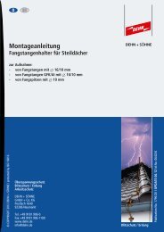
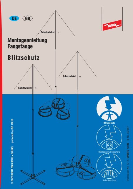
<strong>Montageanleitung</strong><br />
<strong>Fangstange</strong><br />
© COPYRIGHT 2009 DEHN + SÖHNE/ protected by ISO 16016<br />
DE<br />
GB<br />
Blitzschutz<br />
Schutzwinkel a<br />
Schutzwinkel a<br />
Schutzwinkel a<br />
Blitzschutz<br />
Überspannungsschutz<br />
Arbeitsschutz<br />
Publication No. 1712 / UPDATE 12.09 Id-No. 057867
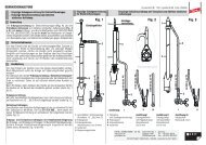
1. Anwendung<br />
Die <strong>Fangstange</strong> eignet sich zum<br />
Errichten von "Getrennten Blitzschutz<br />
Fangeinrichtungen"<br />
nach DIN EN 62305-3 (VDE<br />
0185-305-3).<br />
Beim Einsatz der <strong>Fangstange</strong> ist<br />
das "Schutzwinkelverfahren"<br />
anzuwenden.<br />
Der Schutzwinkel a ist abhänig<br />
von der Schutzklasse (Gefährdungspegel)<br />
und der Höhe der<br />
<strong>Fangstange</strong> über der Bezugsebene.<br />
Die Werte können aus der<br />
DIN EN 62-305-3 (VDE 0185-<br />
305-3),Tabelle 3 entnommen<br />
werden (siehe auch Tabelle 1<br />
und Fig.1).<br />
Gleichermaßen kann bei der<br />
Positionierung der <strong>Fangstange</strong><br />
das Blitzkugelverfahren angewandt<br />
werden.<br />
Die in der <strong>Montageanleitung</strong><br />
spezifizierten <strong>Fangstange</strong>n sind<br />
bis Windlastzone III nach DIN<br />
4131 dimensioniert.<br />
Bei ordnungsgemäßer Montage<br />
können Windgeschwindigkeiten<br />
bis 161 km/h standgehalten werden.<br />
a (°)<br />
80<br />
70<br />
60<br />
50<br />
40<br />
30<br />
20<br />
10<br />
0<br />
Schutzwinkel<br />
a<br />
Schutzklasse I II III IV<br />
0 10 20 30 40 50 60<br />
h (m)<br />
Tabelle 1 Berechnung der <strong>Fangstange</strong><br />
Fig. 1 Schutzwinkel a nach Tabelle 1<br />
Seite 2<br />
Schutzwinkel<br />
a<br />
Schutzwinkel<br />
a<br />
MO_1712_DE_GB_1209_057867
2. <strong>Fangstange</strong>n mit Betonsockel<br />
Die nachfolgend angeführten <strong>Fangstange</strong>n (Tabelle 2) dienen zum Schutz von Dachaufbauten,<br />
mit Anpassung an die Dachneigung bis. max. 10 Grad.<br />
Die <strong>Fangstange</strong>n sind für eine Windgeschwindigkeit bis 145 km/h und 161 km/h<br />
(Windlastzone II + III nach DIN 4131) dimensioniert.<br />
2.1Montage<br />
Bei der Montage der Betonsockel ist darauf zu achten, dass die Streben und die durchgezogene<br />
Betonaussparung der Betonsockel in einer Flucht liegen. Dadurch wird beim Einschlagen der<br />
Befestigungskeile die bestmögliche Stabilität und Standfestigkeit des Strebengestells sowie<br />
der <strong>Fangstange</strong> erreicht (siehe Fig. 2, Seite 4).<br />
2.1.1 Betonsockel<br />
Zur mechanischen Stabilisierung der <strong>Fangstange</strong> und den möglichen Windlastbeeinflussungen<br />
muss an jeder Strebenverankerung ein Betonsockel montiert werden.<br />
In Abhängigkeit der Gesamtlänge der jeweiligen <strong>Fangstange</strong> wird je Strebe ein Betonsockel<br />
mit 8,5 kg oder 17 kg montiert (siehe Tabelle 2 und Fig. 2, Seite 4).<br />
Anmerkung:<br />
Zum zusätzlichen Schutz von Dachbahnen, wird bei der Montage der Betonsockel die Verwendung<br />
von Unterlegplatten Art.-Nr. 102 050 oder 102 060 empfohlen (siehe Fig. 2, Seite 4)<br />
Die Fangeinrichtung darf nicht auf Metall-Blechdächer verwendet werden!<br />
<strong>Fangstange</strong><br />
komplett<br />
Art.-Nr. 105 425<br />
Länge: 2500 mm<br />
Art.-Nr. 105 430<br />
Länge: 3000 mm<br />
Art.-Nr. 105 435<br />
Länge: 3500 mm<br />
Art.-Nr. 105 401<br />
<strong>Fangstange</strong><br />
Æ 16 / 10 mm<br />
Art.-Nr. 103 221<br />
Länge: 2000 mm<br />
Art.-Nr. 103 221<br />
Länge: 2000 mm<br />
Art.-Nr. 103 231<br />
Länge: 2500 mm<br />
Dreibeinstativ<br />
<strong>Fangstange</strong>n-<br />
Unterteil /<br />
Alu-Rohr<br />
Æ 22 x 4 mm<br />
Art.-Nr. 105 405<br />
Länge: 500 mm<br />
Art.-Nr. 105 410<br />
Länge: 1000 mm<br />
Art.-Nr. 105 410<br />
Länge: 1000 mm<br />
Seite 3<br />
Betonsockel<br />
je Strebe<br />
Strebenlänge / Radius<br />
R = 250 mm<br />
Art.-Nr. 102 075<br />
1 x Betonsockel 8,5 kg<br />
Art.-Nr. 102 010<br />
1 x Betonsockel 17 kg<br />
Tabelle 2 <strong>Fangstange</strong>n von 2500 bis 3500 mm<br />
Art.-Nr. 102 010<br />
1 x Betonsockel 17 kg<br />
MO_1712_DE_GB_1209_057867
17 kg<br />
Befestigungskeil<br />
Strebengestell<br />
Strebe (Strebenverankerung)<br />
Fig. 2 Betonsockel<br />
Betonsockel<br />
Art.-Nr. 102 010<br />
Unterlegplatte<br />
Art.-Nr. 102 050<br />
Seite 4<br />
Aufnahme<br />
8,5 kg<br />
Befestigungskeil<br />
Betonsockel<br />
Art.-Nr. 102 075<br />
Unterlegplatte<br />
Art.-Nr. 102 060<br />
MO_1712_DE_GB_1209_057867
2.2 <strong>Fangstange</strong><br />
Die <strong>Fangstange</strong> Æ 16/10 mm wird am oberen Ende des <strong>Fangstange</strong>n-Unterteils Æ 22 x 4 mm<br />
eingeschraubt und mit der Sechskantmutter M 16 gekontert (siehe Fig. 2.2, Seite 6).<br />
Die zusammengeschraubte <strong>Fangstange</strong> wird in den Apdapter des Strebengestelles<br />
senkrecht eingeführt und mittels den vier Arretierungsschrauben M10 (Anzugsdrehmoment;<br />
25 Nm) festgeschraubt.<br />
Dabei müssen die vier Sechskantmuttern M 10 gegen den Adapter gekontert werden<br />
(siehe Fig. 2.2, Seite 6).<br />
2.2.1Ableitung<br />
Der Anschluss der Ableitung (Runddraht 8 - 10 mm) erfolgt über die am <strong>Fangstange</strong>n-Unterteil<br />
angebrachten Stangenklemme (für den Transport positioniert) und ist unter Einhaltung des<br />
erforderlichen Trennungsabstandes mit der nächstgelegenen Fangeinrichtung oder Erdungsanlage<br />
zu verbinden.<br />
Beim Anschluss der Ableitung über die Stangenklemme ist ein Anzugsdrehmoment von 25 Nm<br />
einzuhalten.<br />
Seite 5<br />
MO_1712_DE_GB_1209_057867
Sechskantmutter,<br />
M10<br />
Arretierungsschraube<br />
M10<br />
Fig. 2.2 Strebengestell / Betonsockel / <strong>Fangstange</strong><br />
Seite 6<br />
<strong>Fangstange</strong><br />
Æ 16 / 10 mm (Alu-Rund),<br />
Länge 2000 mm / 2500 mm<br />
Sechskantmutter M 16<br />
<strong>Fangstange</strong>n-<br />
Unterteil / Alu-Rohr<br />
Æ 22 x 4 mm<br />
Stangenklemme<br />
MO_1712_DE_GB_1209_057867
2.3 Anpassung der <strong>Fangstange</strong> bei Dachneigungen bis zu einem Neigungswinkel von 10°<br />
2.3.1Adaptereinstellung<br />
Die am Strebengestell angebrachte Aufnahme ermöglicht die Montage von freistehenden<br />
<strong>Fangstange</strong>n mit einem Durchmesser von 22 mm. Mit dem Adapter können <strong>Fangstange</strong>n<br />
bei Dachneigungen oder auch Geländeneigungen bis zu einem Neigungswinkel von 10°<br />
ausgeglichen werden (siehe Fig. 2.3).<br />
Je nach Ausrichtung des Neigungswinkels wird die <strong>Fangstange</strong> (Æ 22 mm; Alu-Rohr)<br />
in den Adapter eingeführt und mittels den vier Arretierungsschrauben M 10 festgeschraubt.<br />
Zusätzlich müssen die vier Sechskantmuttern gegen den Adapter gekontert werden.<br />
Die vorgegebenen Anzugsdrehmomente sind dabei zu beachten (siehe hierzu Fig. 2.2,<br />
Seite 6 und Fig. 2.3, Seite 7).<br />
Sechskantmutter M10<br />
max. 10°<br />
Fig. 2.3 Adaptereinstellung<br />
Seite 7<br />
<strong>Fangstange</strong>n-Unterteil<br />
Æ 22 x 4 mm; Alu-Rohr<br />
Anzugsdrehmoment<br />
Arretierungsschraube<br />
M 10; 25 Nm<br />
MO_1712_DE_GB_1209_057867
3. <strong>Fangstange</strong>n für Metalldächer<br />
Die nachfolgend angeführten <strong>Fangstange</strong>n (siehe Tabelle 3) dienen zum Schutz von Dachabauten,<br />
Lichtkuppeln, usw.<br />
Die <strong>Fangstange</strong>n sind für eine Windgeschwindigkeit bis 145 km/h und 161 km/h<br />
(Windlastzone II + III nach DIN 4131) dimensioniert.<br />
3.1Montage<br />
Zur mechanischen Stabilisierung der <strong>Fangstange</strong> und den möglichen Windlastbeeinflussungen<br />
muss an jedes Strebenende des Strebengestells (Bohrung Æ11mm) ein Dachleitungshalter<br />
montiert werden (siehe Fig. 3, Seite 9).<br />
3.1.1Dachleitungshalter<br />
Die Dachleitungshalter sind speziell für das jeweilige Dachprofil z.B: Stehfalz, Art.-Nr. 365 059<br />
oder Rundstehfalz Art.-Nr. 223 010 auszuwählen (siehe Fig. 3, Seite 9).<br />
Das max. mögliche eingeleitete Moment von 110 Nm bei WZ II und 136 Nm bei WZ III ist<br />
zu berücksichtigen!<br />
3.1.2 Anpassung des Strebengestells<br />
Das Strebengestell muss je nach Profilabstand (230 - 520 mm) des Metalldaches angepasst<br />
werden. Dazu wird die unterhalb des Strebengestells liegende Sechskantmutter M16 gelockert.<br />
Danach wird das Strebengestell je nach Profilabstand (Abstand der Falzkanten) eingestellt<br />
und auf den Falzkanten des Dachprofils abgesetzt (siehe Fig. 3, Seite 9).<br />
Zuerst empfiehlt es sich die jeweiligen vier Dachleitungshalter an den Falzkanten des Profils<br />
festzuschrauben. Danach erfolgt das Festschrauben der unterhalb des Strebengestells liegende<br />
Sechskantmutter M16. Die entsprechenden Anzugsdrehmomente sind zu beachten. (siehe<br />
Tabelle 3 und Fig. 3, Seite 9).<br />
Anmerkung:<br />
Bei Verwendung dieser vier Dachleitungshalter (Klemmen) für das entsprechende Dachprofil<br />
ist eine Blitzzstromtragfähigkeit mit 100 kA (10/350) gegeben.<br />
<strong>Fangstange</strong><br />
komplett<br />
Art.-Nr. 123 425<br />
Länge: 2500 mm<br />
Art.-Nr. 123 430<br />
Länge: 3000 mm<br />
Art.-Nr. 123 435<br />
Länge: 3500 mm<br />
Art.-Nr. 123 401<br />
<strong>Fangstange</strong><br />
Æ 16 / 10 mm<br />
Art.-Nr. 103 221<br />
Länge: 2000 mm<br />
Art.-Nr. 103 221<br />
Länge: 2000 mm<br />
Art.-Nr. 103 231<br />
Länge: 2500 mm<br />
Strebengestell<br />
<strong>Fangstange</strong>n-<br />
Unterteil /<br />
Alu-Rohr<br />
Æ 22 x 4 mm<br />
Art.-Nr. 105 405<br />
Länge: 500 mm<br />
Art.-Nr. 105 410<br />
Länge: 1000 mm<br />
Art.-Nr. 105 410<br />
Länge: 1000 mm<br />
Seite 8<br />
Leitungshalter /<br />
Klemmen<br />
4 x Art.-Nr. 365 059 /<br />
4 x Art.-Nr. 223 010/<br />
4 x Art.-Nr. 223 070<br />
4 x Art.-Nr. 365 059 /<br />
4 x Art.-Nr. 223 010/<br />
4 x Art.-Nr. 223 070<br />
4 x Art.-Nr. 365 059 /<br />
4 x Art.-Nr. 223 010/<br />
4 x Art.-Nr. 223 070<br />
Profilabstände 230 - 520 mm<br />
Tabelle 3 <strong>Fangstange</strong>n von 2500 bis 3500 mm<br />
MO_1712_DE_GB_1209_057867
Sechskantmutter M8 / 15 Nm<br />
Sechskantmutter<br />
M16 / 70 Nm<br />
Dachprofil,<br />
Typ: yp:<br />
Rundstehfalz<br />
Fig. 3 Strebengestell<br />
Bohrung,Æ 11mm<br />
Dachleitungshalter,<br />
Rundstehfalz,<br />
Art.-Nr. 223 010<br />
oder<br />
Stehfalz,<br />
Art.-Nr. 365 059<br />
(Sechskantmutter<br />
M8 / 15 Nm)<br />
Strebengestell mit<br />
Dachleitungshalter,<br />
Rundstehfalz, Art.-Nr. 223 010<br />
2x Sechskantmutter<br />
M8 /<br />
Anzugsdrehmoment<br />
15 Nm<br />
z.B. Scheibe oder Klemmbock<br />
Seite 9<br />
Strebengestell<br />
Profilabstände 230 - 520 mm<br />
Detail<br />
-Darstellung<br />
Sechskantmutter<br />
M16 / 70 Nm<br />
Sechskantmutter<br />
M16 / 70 Nm<br />
Dachprofil,<br />
Typ: yp:<br />
Stehfalz<br />
Strebenende<br />
Strebengestell mit<br />
Dachleitungshalter,<br />
Stehfalz, Art.-Nr. 365 059<br />
MO_1712_DE_GB_1209_057867
3.2 <strong>Fangstange</strong><br />
Die <strong>Fangstange</strong> Æ 16/10 mm wird am oberen Ende des <strong>Fangstange</strong>n-Unterteils Æ 22 x 4 mm<br />
eingeschraubt und mit der Sechskantmutter M 16 gekontert ( siehe Fig. 3.2, Seite 11).<br />
Die zusammengeschraubte <strong>Fangstange</strong> wird in den Apdapter des Strebengestelles<br />
senkrecht eingeführt und mittels den vier Arretierungsschrauben M8 (Anzugsdrehmoment;<br />
15 Nm) festgeschraubt.<br />
Dabei müssen die vier Sechskantmuttern M8 gegen den Adapter gekontert werden<br />
(siehe Fig. 3.2, Seite 11).<br />
3.2.1Ableitung des Blitzstrom<br />
Die <strong>Fangstange</strong> ist über das Strebengestell und den vier Dachleitungshaltern / Klemmen leitend<br />
mit dem Profildach verbunden. Daher ist ein zusätzliche Ableitung (z.B. mittels Runddraht<br />
8 - 10 mm) auf-/ oder entlang der Dachfläche nicht erforderlich.<br />
Vorausgesetzt ist jedoch dass, das Metalldach in den Äußeren Blitzschutz mit eingebunden ist.<br />
Das Metalldach wird z.B. an der Traufe in das Äußere Blitzschutzsystem mit den entsprechenden<br />
typischen Abständen der Ableitungen eingebunden und somit mit der Erdungsanlage verbunden.<br />
Seite 10<br />
MO_1712_DE_GB_1209_057867
Sechskantmutter,<br />
M8<br />
Arretierungsschraube<br />
M8<br />
Fig. 3.2 Strebengestell / <strong>Fangstange</strong><br />
Seite 11<br />
<strong>Fangstange</strong><br />
Æ 16 / 10 mm (Alu-Rund),<br />
Länge 2000 mm / 2500 mm<br />
Dachprofil<br />
Typ: yp: Rundstehfalz<br />
Sechskantmutter M 16<br />
<strong>Fangstange</strong>n-<br />
Unterteil / Alu-Rohr<br />
Æ 22 x 4 mm<br />
MO_1712_DE_GB_1209_057867
3.3 Anpassung der <strong>Fangstange</strong> bei Dachneigungen bis zu einem Neigungswinkel von 10°<br />
3.3.1Adaptereinstellung<br />
Die am Strebengestell angebrachte Aufnahme ermöglicht die Montage von freistehenden<br />
<strong>Fangstange</strong>n mit einem Durchmesser von 22 mm. Mit dem Adapter können <strong>Fangstange</strong>n<br />
bei Dachneigungen oder auch Geländeneigungen bis zu einem Neigungswinkel von 10°<br />
ausgeglichen werden (siehe Fig. 3.3).<br />
Je nach Ausrichtung des Neigungswinkels wird die <strong>Fangstange</strong> ( 22 mm; Alu-Rohr)<br />
in den Adapter eingeführt und mittels den vier Arretierungsschrauben M8 festgeschraubt.<br />
Zusätzlich müssen die vier Sechskantmuttern gegen den Adapter gekontert werden.<br />
Die vorgegebenen Anzugsdrehmomente sind dabei zu beachten (siehe hierzu Fig. 3.2,<br />
Seite 11 und Fig. 3.3, Seite 12).<br />
Sechskantmutter<br />
M8; 15 Nm<br />
Fig. 3.3 Anpassung <strong>Fangstange</strong><br />
max. 10°<br />
Seite 12<br />
<strong>Fangstange</strong>n-Unterteil<br />
22 x 4 mm; Alu-Rohr<br />
Anzugsdrehmoment<br />
Arretierungsschraube<br />
M 8; 15 Nm<br />
MO_1712_DE_GB_1209_057867
GB DE<br />
Installation Instructions<br />
Air-Termination Rod<br />
Lightning Protection<br />
© COPYRIGHT 2009 DEHN + SÖHNE/ protected by ISO 16016<br />
protective<br />
angle a<br />
protective<br />
angle a<br />
protective<br />
angle a<br />
Lightning Protection<br />
Surge Protection<br />
Safety Equipment<br />
Publication No. 1712 / UPDATE 12.09 Id-No. 057867
1.Use<br />
The air-termination rod is suitable<br />
for installing ”isolated<br />
air-terminations” in accordance<br />
with IEC/EN 62305-3<br />
(VDE 0185-305-3). When<br />
using the air-termination rod,<br />
the ”protective angle method”<br />
has to be applied.<br />
The protective angle a depends<br />
on the class of LPS (lightning<br />
protection level) and the height<br />
of the air-termination rod above<br />
the reference plane.<br />
For more detailed information<br />
on these values, see IEC/EN<br />
62305-3 (VDE 0185-305-3),<br />
Table 3 (see also Table 1 and<br />
Fig. 1).<br />
The rolling sphere method can<br />
also be used for positioning<br />
the air-termination rod.<br />
The air-termination rods specified<br />
in these installation instructions<br />
are designed up to<br />
wind load zone III in accordance<br />
with DIN 4131.<br />
If installed properly, airtermination<br />
rods can withstand<br />
wind speeds up to 161<br />
km/h.<br />
a (°)<br />
80<br />
70<br />
60<br />
50<br />
40<br />
30<br />
20<br />
10<br />
0<br />
protective<br />
angle a<br />
class of LPS I II III IV<br />
0 10 20 30 40 50 60<br />
h (m)<br />
Table 1 Calculation of the air-termination rod<br />
Fig. 1 Protective angle a according to table 1<br />
Page 2<br />
protective<br />
angle a<br />
protective<br />
angle a<br />
MO_1712_DE_GB_1209_057867
2. Air-termination rods with concrete block<br />
The air-termination rods listed below (see table 2) are supposed to protect roof superstructures<br />
and can be adjusted to roof inclinations up to max. 10 degrees.<br />
The air-termination rods are dimensioned for wind speeds up to 145 km/h and 161 km/h<br />
(wind load zone II + III in accordance with DIN 4131).<br />
2.1Installation<br />
When installing the concrete block, it has to be observed that the braces and the continuous<br />
concrete recess of the concrete blocks are aligned in a straight line. Thus, maximum stability<br />
of the brace frame and the air-termination rod is achieved when driving in the wedges (see<br />
Fig. 2, page 4).<br />
2.1.1 Concrete block<br />
For mechanical stabilisation of the air-termination rod and protection against possible wind<br />
load effects, a concrete block has to be installed on every bracing.<br />
Depending on the total length of the relevant air-termination rod, a concrete block with a<br />
weight of 8.5 kg or 17 kg is installed per brace (see table 2 and Fig. 2, page 4).<br />
Note:<br />
For additional protection of roof sheetings it is advisable to use ground plates, Part No. 102<br />
050 or 102 060, when installing the concrete blocks (see Fig. 2, page 4).<br />
The air-termination system may not be installed on sheet metal roofs!<br />
Complete airtermination-rod<br />
Part No. 105 425<br />
Length: 2500 mm<br />
Part No. 105 430<br />
Length: 3000 mm<br />
Part No. 105 435<br />
Length: 3500 mm<br />
Part No. 105 401<br />
Air-terminationrod<br />
with a<br />
diameter of<br />
Æ 16 / 10 mm<br />
Part No. 103 221<br />
Length: 2000 mm<br />
Part No. 103 221<br />
Length: 2000 mm<br />
Part No. 103 231<br />
Length: 2500 mm<br />
Tripod<br />
Lower part of the<br />
air-termination<br />
rod / aluminium tube<br />
Æ 22 x 4 mm<br />
Part No. 105 405<br />
Length: 500 mm<br />
Part No. 105 410<br />
Length: 1000 mm<br />
Part No. 105 410<br />
Length: 1000 mm<br />
Page 3<br />
Concrete block<br />
per brace<br />
Brace length / radius<br />
R = 250 mm<br />
Part No. 102 075<br />
1 x concrete block 8,5 kg<br />
Part No. 102 010<br />
1 x concrete block 17 kg<br />
Part No. 102 010<br />
1 x concrete block 17 kg<br />
Table 2 Air-termination rods from 2500 bis 3500 mm<br />
MO_1712_DE_GB_1209_057867
ace<br />
(bracing)<br />
wedge<br />
brace frame<br />
17 kg<br />
Fig. 2 concrete block<br />
concrete block<br />
Art.-Nr. 102 010<br />
ground plate<br />
Art.-Nr. 102 050<br />
Page 4<br />
adapter<br />
wedge<br />
8,5 kg<br />
concrete block<br />
Art.-Nr. 102 075<br />
ground plate<br />
Art.-Nr. 102 060<br />
MO_1712_DE_GB_1209_057867
2.2 Air-termination rod<br />
The air-termination rod with a diameter of 16/10 mm is screwed into the top of the lower part<br />
of the air-termination rod (Æ 22 x 4 mm) and the M 16 hexagon nut is tightened (see Fig. 2.2,<br />
page 6).<br />
The assembled air-termination rod is vertically inserted into the adapter of the brace frame and<br />
the four M10 locking bolts are tightened (tightening torque of 25 Nm).<br />
The four M10 hexagon nuts have to be tightened against the adapter (see Fig. 2.2, page 6).<br />
2.2.1 Down conductor<br />
The down conductor (round wire 8-10 mm) is connected via a rod clamp (positioned for<br />
transport) on the lower part of the air-termination rod and has to be connected to the next airtermination<br />
system or earth-termination system while maintaining the required separation<br />
distance.<br />
A tightening torque of 25 Nm has to be applied when connecting the down conductor via the<br />
rod clamp.<br />
Page 5<br />
MO_1712_DE_GB_1209_057867
hexagon nut,<br />
M10<br />
locking bolt<br />
M10<br />
Fig. 2.2 Brace frame / concrete block / air-termination rod<br />
Page 6<br />
air-termination rod<br />
Æ 16 / 10 mm (round aluminium),<br />
length 2000 mm / 2500 mm<br />
M 16 hexagon nut<br />
lower part of the air-termination<br />
rod / aluminium tube<br />
Æ 22 x 4 mm<br />
rod clamp<br />
MO_1712_DE_GB_1209_057867
2.3. Adjustment of the air-termination rod in case of roof inclinations up to an inclination angle<br />
of 10°<br />
2.3.1Adjustment of the adapter<br />
The adapter attached to the brace frame allows the installation of self-supporting air-termination<br />
rods with a diameter of 22 mm. This adapter compensates air-termination rods in case of<br />
roof inclinations or slopes up to an inclination angle of 10° (see Fig. 2.3).<br />
Depending on the inclination angle, the air-termination rod (Æ 22 mm; aluminium tube) is<br />
inserted into the adapter and the four M10 locking bolts are tightened.<br />
Moreover, the four hexagon nuts have to tightened against the adapter. The specified tightening<br />
torques have to be observed (see Fig. 2.2, page 6 and Fig. 2.3, page 7).<br />
M10 hexagon nut<br />
max. 10°<br />
Fig. 2.3 Adjustment of the adapter<br />
Page 7<br />
lower part of the<br />
air-termination rod<br />
Æ 22 x 4 mm; aluminium tube<br />
tightening torque for the<br />
M10 locking bolt;<br />
25 Nm<br />
MO_1712_DE_GB_1209_057867
3. Air-termination rods for metal roofs<br />
The air-termination rods listed below (see table 3) are supposed to protect roof superstructures,<br />
dome lights, etc.<br />
The air-termination rods are dimensioned for wind speeds up to 145 km/h and 161 km/h<br />
(wind load zone II + III in accordance with DIN 4131).<br />
3.1Installation<br />
For mechanical stabilisation of the air-termination rod and protection against possible wind<br />
load effects, a roof conductor holder has to be installed on every brace end of the brace frame<br />
(hole with a diameter of 11 mm) (see Fig. 3, page 9).<br />
3.1.1 Roof conductor holders<br />
The roof conductor holders have to be specifically selected for the relevant roof profile e.g.<br />
standing seam, Part No. 365 059, or round standing seam, Part No. 223 010 (see Fig. 3, page<br />
9).<br />
The max. torque of 110 Nm for wind load zone II and 136 Nm for wind load zone III has to<br />
be observed!<br />
3.1.2Adjustment of the brace frame<br />
The brace frame has to be adjusted according on the profile clearance (230 to 520 mm) of<br />
the metal roof. For this purpose, the M16 hexagon nut below the brace frame is loosened.<br />
After that, the brace frame is adjusted according on the profile clearance (clearance of the<br />
seam edges) and placed on the seam edges of the roof profile (see Fig. 3, page 9).<br />
It is advisable to tighten the relevant four roof conductor holders on the seam edges of the<br />
profile. After that, the M16 hexagon nut below the brace frame is tightened. Observe the<br />
relevant tightening torques (see table 3 and Fig. 3, page 9).<br />
Note:<br />
When using these four roof conductor holders (clamps) for the relevant roof profile a lightning<br />
current carrying capability of 100 kA (10/350) is ensured.<br />
Complete airtermination-rod<br />
Part No. 123 425<br />
Length: 2500 mm<br />
Part No. 123 430<br />
Length: 3000 mm<br />
Part No. 123 435<br />
Length: 3500 mm<br />
Part No. 123 401<br />
Air-terminationrod<br />
with a diameter<br />
of 16 / 10 mm<br />
Part No. 103 221<br />
Length: 2000 mm<br />
Part No. 103 221<br />
Length: 2000 mm<br />
Part No. 103 231<br />
Length: 2500 mm<br />
Brace frame<br />
Lower part of the<br />
air-termination rod /<br />
aluminium tube<br />
Æ 22 x 4 mm<br />
Part No. 105 405<br />
Length: 500 mm<br />
Part No. 105 410<br />
Length: 1000 mm<br />
Part No. 105 410<br />
Length: 1000 mm<br />
Profile clearances 230 - 520 mm<br />
Table 3 Air-termination rods from 2500 to 3500 mm<br />
Page 8<br />
Conductor holders /<br />
clamps<br />
4 x Part No. 365 059 /<br />
4 x Part No. 223 010/<br />
4 x Part No.. 223 070<br />
4 x Part No. 365 059 /<br />
4 x Part No. 223 010/<br />
4 x Part No. 223 070<br />
4 x Part No. 365 059 /<br />
4 x Part No. 223 010/<br />
4 x Part No. 223 070<br />
MO_1712_DE_GB_1209_057867
Roof profile,<br />
type: round<br />
standing seam<br />
hole Æ 11 mm ,<br />
roof conductor holder,<br />
round standing seam,<br />
Part No.223 010 or<br />
standing seam,<br />
Part No. 365 059<br />
M16 hexagon nut<br />
/ 70 Nm<br />
Fig. 3 Brace frame<br />
M8 hexagon nut / 15 Nm<br />
(M8 hexagon nut<br />
/ 15 Nm)<br />
brace frame with roof conductor<br />
holder, round standing seam,<br />
Part No. 223 010<br />
2 M8 hexagon nuts /<br />
tightening torque<br />
of 15 Nm<br />
Page 9<br />
brace frame<br />
profile clearances 230 - 520 mm<br />
Detailed<br />
view<br />
e.g. flat washer or clamping frame<br />
M16 hexagon<br />
nut / 70 Nm<br />
M16 hexagon nut<br />
/ 70 Nm<br />
Roof profile,<br />
type: standing<br />
seam<br />
brace end<br />
brace frame with roof conductor<br />
holder, standing seam,<br />
Part No. 365 059<br />
MO_1712_DE_GB_1209_057867
3.2 Air-termination rod<br />
The air-termination rod with a diameter of 16/10 mm is screwed into the top of the lower part<br />
of the air-termination rod ( Æ 22 x 4 mm) and the M 16 hexagon nut is tightened (see Fig. 3.2,<br />
page 11).<br />
The assembled air-termination rod is vertically inserted into the adapter of the brace frame and<br />
the four M8 locking bolts are tightened (tightening torque of 15 Nm).<br />
The four M8 hexagon nuts have to be tightened against the adapter (see Fig. 3.2, page 11).<br />
3.2.1Discharge of lightning current<br />
The air-termination rod is electrically connected to the profile roof via the brace frame and the<br />
four conductor holders / clamps. Therefore, an additional down conductor (e.g. by means of a<br />
round wire 8-10 mm) on or along the roof area is not required provided that the metal roof is<br />
integrated into the external lightning protection system.<br />
The metal roof is integrated into the external lightning protection system e.g. at the eaves while<br />
maintaining the typical the down conductor clearances and is thus connected to the earthtermination<br />
system.<br />
Page 10<br />
MO_1712_DE_GB_1209_057867
M8 hexagon nut<br />
M8 locking bolt<br />
Fig. 3.2 Brace frame / air-termination rod<br />
Page 11<br />
Roof profile<br />
type: round<br />
standing seam<br />
air-termination rod Æ 16/10 mm<br />
(round aluminium),<br />
length 2000 mm / 2500 mm<br />
M16 hexagon nut<br />
lower part of the<br />
air-termination rod /<br />
aluminium tube Æ 22 x 4 mm<br />
MO_1712_DE_GB_1209_057867
3.3 Adjustment of the air-termination rod in case of roof inclinations up to an inclination angle<br />
of 10°<br />
3.3.1 Adjustment of the adapter<br />
The adapter attached to the brace frame allows the installation of self-supporting air-termination<br />
rods with a diameter of 22 mm. This adapter compensates air-termination rods in case of roof<br />
inclinations or slopes up to an inclination angle of 10° (see Fig. 3.3).<br />
Depending on the inclination angle, the air-termination rod ( 22 mm; aluminium tube) is<br />
inserted into the adapter and the four M8 locking bolts are tightened.<br />
Moreover, the four hexagon nuts have to tightened against the adapter. The specified tightening<br />
torques have to be observed (see Fig. 3.2, page 11 and Fig. 3.3, page 12.<br />
M8 hexagon nut<br />
15 Nm<br />
max. 10°<br />
Fig. 3.3 Adjustment of the air-termination rod<br />
Page 12<br />
lower part of the<br />
air-termination rod<br />
22 x 4 mm; aluminium tube<br />
tightening torque for the<br />
M8 locking bolt<br />
M 8; 15 Nm<br />
MO_1712_DE_GB_1209_057867