Montageanleitung Fangstange - Dehn + Söhne Blitzschutzsysteme
Montageanleitung Fangstange - Dehn + Söhne Blitzschutzsysteme
Montageanleitung Fangstange - Dehn + Söhne Blitzschutzsysteme

Sie wollen auch ein ePaper? Erhöhen Sie die Reichweite Ihrer Titel.
YUMPU macht aus Druck-PDFs automatisch weboptimierte ePaper, die Google liebt.
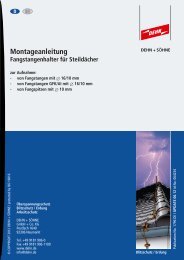
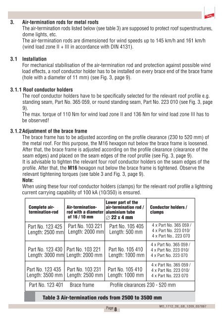
3. Air-termination rods for metal roofs<br />
The air-termination rods listed below (see table 3) are supposed to protect roof superstructures,<br />
dome lights, etc.<br />
The air-termination rods are dimensioned for wind speeds up to 145 km/h and 161 km/h<br />
(wind load zone II + III in accordance with DIN 4131).<br />
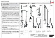
3.1Installation<br />
For mechanical stabilisation of the air-termination rod and protection against possible wind<br />
load effects, a roof conductor holder has to be installed on every brace end of the brace frame<br />
(hole with a diameter of 11 mm) (see Fig. 3, page 9).<br />
3.1.1 Roof conductor holders<br />
The roof conductor holders have to be specifically selected for the relevant roof profile e.g.<br />
standing seam, Part No. 365 059, or round standing seam, Part No. 223 010 (see Fig. 3, page<br />
9).<br />
The max. torque of 110 Nm for wind load zone II and 136 Nm for wind load zone III has to<br />
be observed!<br />
3.1.2Adjustment of the brace frame<br />
The brace frame has to be adjusted according on the profile clearance (230 to 520 mm) of<br />
the metal roof. For this purpose, the M16 hexagon nut below the brace frame is loosened.<br />
After that, the brace frame is adjusted according on the profile clearance (clearance of the<br />
seam edges) and placed on the seam edges of the roof profile (see Fig. 3, page 9).<br />
It is advisable to tighten the relevant four roof conductor holders on the seam edges of the<br />
profile. After that, the M16 hexagon nut below the brace frame is tightened. Observe the<br />
relevant tightening torques (see table 3 and Fig. 3, page 9).<br />
Note:<br />
When using these four roof conductor holders (clamps) for the relevant roof profile a lightning<br />
current carrying capability of 100 kA (10/350) is ensured.<br />
Complete airtermination-rod<br />
Part No. 123 425<br />
Length: 2500 mm<br />
Part No. 123 430<br />
Length: 3000 mm<br />
Part No. 123 435<br />
Length: 3500 mm<br />
Part No. 123 401<br />
Air-terminationrod<br />
with a diameter<br />
of 16 / 10 mm<br />
Part No. 103 221<br />
Length: 2000 mm<br />
Part No. 103 221<br />
Length: 2000 mm<br />
Part No. 103 231<br />
Length: 2500 mm<br />
Brace frame<br />
Lower part of the<br />
air-termination rod /<br />
aluminium tube<br />
Æ 22 x 4 mm<br />
Part No. 105 405<br />
Length: 500 mm<br />
Part No. 105 410<br />
Length: 1000 mm<br />
Part No. 105 410<br />
Length: 1000 mm<br />
Profile clearances 230 - 520 mm<br />
Table 3 Air-termination rods from 2500 to 3500 mm<br />
Page 8<br />
Conductor holders /<br />
clamps<br />
4 x Part No. 365 059 /<br />
4 x Part No. 223 010/<br />
4 x Part No.. 223 070<br />
4 x Part No. 365 059 /<br />
4 x Part No. 223 010/<br />
4 x Part No. 223 070<br />
4 x Part No. 365 059 /<br />
4 x Part No. 223 010/<br />
4 x Part No. 223 070<br />
MO_1712_DE_GB_1209_057867