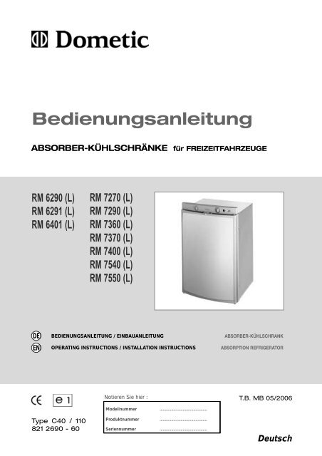
Bedienungsanleitung - Electrolux-ui.com
Bedienungsanleitung - Electrolux-ui.com
Bedienungsanleitung - Electrolux-ui.com

Erfolgreiche ePaper selbst erstellen
Machen Sie aus Ihren PDF Publikationen ein blätterbares Flipbook mit unserer einzigartigen Google optimierten e-Paper Software.
<strong>Bedienungsanleitung</strong><br />
ABSORBER-KÜHLSCHRÄNKE für FREIZEITFAHRZEUGE<br />
RM 6290 (L)<br />
RM 6291 (L)<br />
RM 6401 (L)<br />
DE<br />
EN<br />
BEDIENUNGSANLEITUNG / EINBAUANLEITUNG<br />
OPERATING INSTRUCTIONS / INSTALLATION INSTRUCTIONS<br />
Type C40 / 110<br />
821 2690 - 60<br />
RM 7270 (L)<br />
RM 7290 (L)<br />
RM 7360 (L)<br />
RM 7370 (L)<br />
RM 7400 (L)<br />
RM 7540 (L)<br />
RM 7550 (L)<br />
Notieren Sie hier :<br />
Modellnummer .............................................<br />
Produktnummer .............................................<br />
Seriennummer .............................................<br />
ABSORBER-KÜHLSCHRANK<br />
ABSORPTION REFRIGERATOR<br />
T.B. MB 05/2006<br />
Deutsch
Dansk<br />
Deutsch<br />
Ελληνικά<br />
English<br />
Español<br />
Français<br />
Italiano<br />
Nederlands<br />
Norsk<br />
Português<br />
Suomi<br />
Svensk<br />
Information<br />
Sicherheitshinweis<br />
Umwelthinweis<br />
via INTERNET<br />
www.dometic.<strong>com</strong><br />
Kundendienst<br />
Anweisung zur Einlagerung von Lebensmitteln in einen Kühlschrank:<br />
Kühlgeräte jeder Art können die Qualität von Lebensmitteln nicht verbessern, sondern maximal die Qualiltät der Lebensmittel<br />
zum Zeitpunkt der Einlagerung über einen kurzen Zeitraum erhalten.<br />
Berücksichtigen Sie folgende besondere Bedingungen beim Aufbewahren von Lebensmitteln in einem Kühlschrank , der in<br />
einem Fahrzeug eingebaut ist :<br />
- Veränderung der klimatischen Bedingungen, wie Temperaturänderungen<br />
- Hohe Innentemperatur, wenn das Fahrzeug geschlossen geparkt und der direkten Sonnenbestrahlung ausgesetzt ist<br />
( mögliche Temperatur bis zu 50°C)<br />
- Gebrauch des Kühlschranks während der Fahrt mit der Energiequelle 12V--DC<br />
- Kühlschrank eingebaut hinter einem Fenster und direkte Sonnenbestrahlung<br />
- Zu schnelles Einlagern von Waren kurz nach Inbetriebnahme des Gerätes<br />
Bei diesen besonderen Bedingungen kann der Kühlschrank die benötigte Temperatur für schnell verderbliche Lebensmittel<br />
nicht garantieren.<br />
Zu den schnell verderblichen Waren gehören: alle Produkte mit angegebenem Verfallsdatum und Mindestaufbewahrungstemperatur<br />
von +4°C oder weniger, besonders Fleisch, Geflügel, Fisch, Wurst, Fertiggerichte.<br />
Hinweise<br />
- Rohe und gekochte Waren separat verpacken (z.B. Behälter, Alu-Folie o.ä.).<br />
- Umverpackungen von Einzelverpackungen nur entfernen, wenn alle nötigen Daten wie z.B. Verfallsdatum auch<br />
auf den Einzelverpackungen abzulesen sind.<br />
- Gekühlte Ware nicht zu lange außerhalb des Kühlschranks belassen.<br />
- Lebensmittel mit dem jüngsten Verfallsdatum nach vorne stellen.<br />
- Reste wieder verpacken und schnellstmöglich verzehren.<br />
- Hände vor und nach dem Berühren von Lebensmittel waschen.<br />
- Innenraum des Kühlschranks in regelmäßigen Abständen reinigen.<br />
Information :<br />
Beachten Sie die Hinweise und Beschreibungen zum Verfallsdatum auf den Warenumverpackungen.<br />
Beachten Sie in dieser Anleitung die Abschnitte “5.1 Reinigung” und “5.3 Einlagern von Lebensmitteln”.<br />
Bewahren Sie diese Gebrauchsanweisung sorgfältig auf.<br />
Bei Weitergabe des Gerätes legen Sie diese Gebrauchsanweisung bitte bei.<br />
© Dometic GmbH - 2003 - Änderungen vorbehalten - Gedruckt in Deutschland<br />
2<br />
Achtung<br />
Warnung
INHALTSVERZEICHNIS<br />
1.0 VORWORT . . . . . . . . . . . . . . . . . . . . . . . . . . . . . . . . . . . . . . . . . . . 4<br />
2.0 FÜR IHRE SICHERHEIT . . . . . . . . . . . . . . . . . . . . . . . . . . . . . . . . . 4<br />
2.1 Warn- und Sicherheitshinweise . . . . . . . . . . . . . . . . . . . . . . . . . . . . . . . . . . . . . . . . . . . . . . . . . 4<br />
2.2 Kältemittel . . . . . . . . . . . . . . . . . . . . . . . . . . . . . . . . . . . . . . . . . . . . . . . . . . . . . . . . . . . . . . . . . . 4<br />
3.0 GARANTIE UND KUNDENDIENST . . . . . . . . . . . . . . . . . . . . . . . . 5<br />
4.0 MODELLBESCHREIBUNG . . . . . . . . . . . . . . . . . . . . . . . . . . . . . . . 5<br />
5.0 ANLEITUNG KÜHLSCHRANK . . . . . . . . . . . . . . . . . . . . . . . . . . . . 5<br />
5.1 Reinigung . . . . . . . . . . . . . . . . . . . . . . . . . . . . . . . . . . . . . . . . . . . . . . . . . . . . . . . . . . . . . . . . . . 5<br />
5.2 Bedienen des Kühlschranks . . . . . . . . . . . . . . . . . . . . . . . . . . . . . . . . . . . . . . . . . . . . . . . . . . . . 6<br />
5.3 Einlagern von Lebensmitteln . . . . . . . . . . . . . . . . . . . . . . . . . . . . . . . . . . . . . . . . . . . . . . . . . . . 9<br />
5.4 Eiswürfelbereitung . . . . . . . . . . . . . . . . . . . . . . . . . . . . . . . . . . . . . . . . . . . . . . . . . . . . . . . . . . . 10<br />
5.5 Ablageroste positionieren . . . . . . . . . . . . . . . . . . . . . . . . . . . . . . . . . . . . . . . . . . . . . . . . . . . . . . 10<br />
5.6 Türverriegelung . . . . . . . . . . . . . . . . . . . . . . . . . . . . . . . . . . . . . . . . . . . . . . . . . . . . . . . . . . . . . 10<br />
5.7 Abtauen . . . . . . . . . . . . . . . . . . . . . . . . . . . . . . . . . . . . . . . . . . . . . . . . . . . . . . . . . . . . . . . . . . . 11<br />
5.8 Winterbetrieb . . . . . . . . . . . . . . . . . . . . . . . . . . . . . . . . . . . . . . . . . . . . . . . . . . . . . . . . . . . . . . . 11<br />
5.9 Abschalten des Kühlschranks . . . . . . . . . . . . . . . . . . . . . . . . . . . . . . . . . . . . . . . . . . . . . . . . . . 12<br />
5.10 Batteriewechsel am Batteriezünder . . . . . . . . . . . . . . . . . . . . . . . . . . . . . . . . . . . . . . . . . . . . . . 12<br />
5.11 Beleuchtung . . . . . . . . . . . . . . . . . . . . . . . . . . . . . . . . . . . . . . . . . . . . . . . . . . . . . . . . . . . . . . . . 12<br />
5.12 Wechsel der Dekorplatte . . . . . . . . . . . . . . . . . . . . . . . . . . . . . . . . . . . . . . . . . . . . . . . . . . . . . . 13<br />
5.13 Türanschlag wechseln . . . . . . . . . . . . . . . . . . . . . . . . . . . . . . . . . . . . . . . . . . . . . . . . . . . . . . . . 14<br />
5.14 Verhalten bei Störungen . . . . . . . . . . . . . . . . . . . . . . . . . . . . . . . . . . . . . . . . . . . . . . . . . . . . . . . 15<br />
5.15 Wartung . . . . . . . . . . . . . . . . . . . . . . . . . . . . . . . . . . . . . . . . . . . . . . . . . . . . . . . . . . . . . . . . . . . 16<br />
5.16 Produkthaftung . . . . . . . . . . . . . . . . . . . . . . . . . . . . . . . . . . . . . . . . . . . . . . . . . . . . . . . . . . . . . . 16<br />
5.17 Umwelthinweise . . . . . . . . . . . . . . . . . . . . . . . . . . . . . . . . . . . . . . . . . . . . . . . . . . . . . . . . . . . . . 16<br />
5.18 Entsorgung . . . . . . . . . . . . . . . . . . . . . . . . . . . . . . . . . . . . . . . . . . . . . . . . . . . . . . . . . . . . . . . . . 16<br />
5.19 Energiesparhinweise . . . . . . . . . . . . . . . . . . . . . . . . . . . . . . . . . . . . . . . . . . . . . . . . . . . . . . . . . 16<br />
5.20 Technische Daten . . . . . . . . . . . . . . . . . . . . . . . . . . . . . . . . . . . . . . . . . . . . . . . . . . . . . . . . . . . . 17<br />
5.21 Konformitätserklärung . . . . . . . . . . . . . . . . . . . . . . . . . . . . . . . . . . . . . . . . . . . . . . . . . . . . . . . . 17<br />
6.0 EINBAUANLEITUNG . . . . . . . . . . . . . . . . . . . . . . . . . . . . . . . . . . . . 18<br />
6.1 Installation . . . . . . . . . . . . . . . . . . . . . . . . . . . . . . . . . . . . . . . . . . . . . . . . . . . . . . . . . . . . . . . . . 18<br />
6.2 Zugdichter Einbau . . . . . . . . . . . . . . . . . . . . . . . . . . . . . . . . . . . . . . . . . . . . . . . . . . . . . . . . . . . 20<br />
6.3 Be-und Entlüftung . . . . . . . . . . . . . . . . . . . . . . . . . . . . . . . . . . . . . . . . . . . . . . . . . . . . . . . . . . . . 21<br />
6.4 Einbau Lüftungssystem . . . . . . . . . . . . . . . . . . . . . . . . . . . . . . . . . . . . . . . . . . . . . . . . . . . . . . . 22<br />
6.5 Einbaunische . . . . . . . . . . . . . . . . . . . . . . . . . . . . . . . . . . . . . . . . . . . . . . . . . . . . . . . . . . . . . . . 23<br />
6.6 Kühlschrankbefestigung . . . . . . . . . . . . . . . . . . . . . . . . . . . . . . . . . . . . . . . . . . . . . . . . . . . . . . . 23<br />
6.7 Abgasführung . . . . . . . . . . . . . . . . . . . . . . . . . . . . . . . . . . . . . . . . . . . . . . . . . . . . . . . . . . . . . . . 24<br />
6.8 Gasinstallation . . . . . . . . . . . . . . . . . . . . . . . . . . . . . . . . . . . . . . . . . . . . . . . . . . . . . . . . . . . . . . 25<br />
6.9 Elektrische Installation . . . . . . . . . . . . . . . . . . . . . . . . . . . . . . . . . . . . . . . . . . . . . . . . . . . . . . . . 27<br />
3
1.0<br />
2.0<br />
2.1<br />
2.2<br />
VORWORT<br />
Mit dem Absorber Kühlschrank von Dometic haben Sie eine gute Wahl<br />
getroffen. Wir sind davon überzeugt, dass Sie ihr neues Gerät in jeder<br />
Hinsicht voll zufrieden stellen wird. Dieser Kühlschrank entspricht hohen<br />
Qualitätsanforderungen und gewährleistet einen effizienten Umgang mit Ressourcen<br />
und Energien im gesamten Lebenslauf - bei Herstellung, Nutzung und Entsorgung.<br />
Bevor Sie das Gerät in Betrieb nehmen, lesen Sie bitte die Installations- und<br />
<strong>Bedienungsanleitung</strong> sorgfältig durch.<br />
Der Kühlschrank ist für den Einbau in Freizeitfahrzeuge, wie Wohnwagen<br />
oder Reisemobile vorgesehen. Das Gerät ist für diese Anwendung in<br />
Konformität mit der EU-Gasrichtlinie 90/396/EWG baumustergeprüft.<br />
FÜR IHRE SICHERHEIT<br />
Warn- und Sicherheitshinweise<br />
Das Gerät niemals mit einer offenen Flamme auf Undichtigkeit<br />
überprüfen.<br />
Kinder schützen!<br />
Demontieren Sie bei Entsorgung des Kühlschrankes alle Kühlschranktüren<br />
und belassen Sie die Ablageroste im Kühlgerät. Ein versehentliches<br />
Einschliessen oder Ersticken wird verhindert.<br />
Bei Gasgeruch:<br />
- Absperrhahn der Gasversorgung und das Flaschenventil schliessen.<br />
- Fenster öffnen und den Raum verlassen.<br />
- keine elektrischen Schalter betätigen.<br />
- offene Flammen löschen.<br />
Das Absorberkühlaggregat niemals öffnen, es steht unter hohem Druck.<br />
Arbeiten an den Gas-, Abgas- und Elektroeinrichtungen dürfen nur von<br />
einem zugelassenen Fachmann ausgeführt werden.<br />
Der Betriebsdruck muss unbedingt der Angabe am Typenschild des<br />
Gerätes entsprechen.<br />
Vergleichen Sie die Angabe des Betriebsdruckes auf dem Typenschild mit<br />
den Daten des Druckminderers an der Flüssiggasflasche.<br />
Das Betreiben des Gerätes mit Gas ist auf Fähren nicht gestattet.<br />
Abdeckungen, die die elektrische Sicherheit gewährleisten, dürfen nur mit einem<br />
geeigneten Werkzeug entfernt werden.<br />
Das Gerät darf nicht dem Regen ausgesetzt werden.<br />
Das Gerät ist nicht für die fachgerechte Lagerung von Medikamenten vorgesehen.<br />
Kältemittel<br />
Als Kältemittel wird Ammoniak verwendet.<br />
Dies ist eine natürliche Verbindung, die auch in Haushaltsreinigern enthalten ist.<br />
(1 Liter Salmiakreiniger enthält bis zu 200 g Ammoniak, ca. doppelt soviel, wie im<br />
Kühlgerät enthalten ist). Natriumchromat wird als Korrosionsschutzmittel verwendet<br />
(1,8% des Lösungsmittels). Bei einer eventuell auftretenden Leckage (leicht erkennbar<br />
wegen des unangenehmen Geruchs):<br />
Das Gerät abschalten.<br />
Den Raum gut durchlüften.<br />
Den autorisierten Kundendienst informieren.<br />
4
3.0<br />
4.0<br />
5.0<br />
5.1<br />
GARANTIE UND KUNDENDIENST<br />
Garantieabwicklungen erfolgen nach der EC Directive 44/1999/CE und den<br />
landesüblichen Bedingungen. Im Garantie- oder Servicefall wenden Sie sich<br />
bitte an unseren Kundendienst.<br />
Störungen, die auf fehlerhafte Bedienung zurückzuführen sind, unterliegen<br />
nicht der Garantie. Jede Veränderung am Gerät oder die Verwendung von<br />
Ersatzteilen, die keine Original - Dometic - Ersatzteile sind, sowie das<br />
Nichteinhalten der Einbau- und Gebrauchsanweisung führt zum Erlöschen der<br />
Garantie und zum Ausschluss von Haftungsansprüchen. Ersatzteile können<br />
europaweit von unseren Kundendienststellen bezogen werden.<br />
Bei Kontakten mit dem Kundendienst geben Sie bitte immer das Modell,<br />
Produktnummer, Seriennummer und ggf. den MLC - Code an! Diese Informationen<br />
finden Sie auf dem Typenschild im Innenraum des Kühlschrankes.<br />
MODELLBESCHREIBUNG<br />
z.B.<br />
ANLEITUNG KÜHLSCHRANK<br />
Reinigung<br />
Bevor Sie den Kühlschrank in Betrieb setzen, empfiehlt es sich, das Gerät<br />
von innen und aussen zu reinigen und dies regelmäßig zu wiederholen.<br />
Benutzen Sie ein weiches Tuch, lauwarmes Wasser mit einem milden<br />
Reinigungsmittel.<br />
Anschliessend das Gerät mit klarem Wasser nachwaschen und gut<br />
abtrocknen.<br />
In jährlichen Abständen, das Kühlschrankaggregat mit einem Pinsel<br />
oder weichen Lappen von Staub befreien.<br />
ACHTUNG<br />
RM 7550 L<br />
Refrigerator Mobile /<br />
Mobiler Absorberkühlschrank<br />
Modellreihe<br />
Zur Vermeidung von Materialverschlechterungen:<br />
Verwenden Sie keine Seife oder scharfe, körnige bzw. sodahaltige<br />
Reinigungsmittel.<br />
Die Türdichtung nicht mit Öl oder Fett in Berührung bringen.<br />
5<br />
“L” mit Beleuchtung<br />
1 = automatische Zündung<br />
0 = manuelle Zündung<br />
0 = flache Tür<br />
5 = gebogene Tür
5.2<br />
5.2.1<br />
Bedienen des Kühlschrankes<br />
Das Kühlschrankaggregat arbeitet geräuschlos.<br />
Bei Erstinbetriebnahme des Gerätes kann es zu einer Geruchsbildung<br />
kommen, die sich nach einigen Stunden verflüchtigt.<br />
Den Wohnraum gut durchlüften.<br />
Der Kühlschrank erreicht seine Betriebstemperatur nach einigen Stunden,<br />
wobei das Tiefkühlfach etwa nach einer Stunde kalt werden sollte.<br />
Bedienelemente<br />
A. Manuelle Zündung “Piezozündung” (z.B. RM 6290L oder RM 7400L+)<br />
A<br />
A = Energiewahlschalter<br />
B = Gas / Elektrothermostat<br />
C = Druckknopf “Manuelle Zündung (Piezozünder, optional Batteriezünder)”<br />
D = Flammenanzeige ( Galvanometer)<br />
A B<br />
B. Automatische Zündung ( z.B. RM 6291L)<br />
A B D<br />
A = Energiewahlschalter<br />
B = Gas / Elektrothermostat<br />
D = Anzeige “Automatische Zündung”<br />
Erläuterungen:<br />
Der Kühlschrank kann entweder mit Netzspannung, mit 12V oder Flüssiggas betrieben<br />
werden.<br />
Die gewünschte Energieart wird mit Hilfe des Energiewahlschalters (A) eingestellt.<br />
Der Energiewahlschalter (A) hat vier Stellungen:<br />
Netzspannung , Gleichspannung (Batterie), Flüssiggas, Aus (O) .<br />
Aus<br />
Netzspannung 230V<br />
Gleichspannung 12V<br />
Gas<br />
6<br />
B<br />
C<br />
C D
5.2.2<br />
5.2.3<br />
Betrieb mit Strom<br />
1. Gleichspannung 12V<br />
Der Kühlschrank ist nur bei laufendem Motor über das Bordnetz zu<br />
betreiben.<br />
Den Energiewahlschalter (A) auf 12 V stellen.<br />
Der Kühlschrank arbeitet ohne thermostatische<br />
Regelung (Dauerbetrieb).<br />
2. Wechselspannung<br />
Diese Betriebsart ist nur zu wählen, wenn die Spannungsversorgung des<br />
Stromanschlusses mit dem auf dem Typenschild angegebenen Wert übereinstimmt.<br />
Bei abweichenden Werten kann das Gerät beschädigt werden.<br />
A<br />
1. Den Energiewahlschalter<br />
(A) auf<br />
230 V stellen. B<br />
Betrieb mit Gas<br />
<br />
<br />
<br />
<br />
Der Kühlschrank muss ausschliesslich mit Flüssiggas (Propan, Butan)<br />
betrieben werden ( kein Erdgas, Autogas, Stadtgas) .<br />
Beim Betrieb des Kühlschranks mit Gas während der Fahrt müssen die<br />
nationalen Verordnungen des jeweiligen Landes beachtet werden<br />
( gemäß EN 732 ).<br />
Über einer Höhe von ca. 1000 m NN können beim Zünden des Gases<br />
physikalisch bedingt Störungen auftreten (Keine Fehlfunktion !).<br />
Im Tankstellenbereich ist der Gasbetrieb grundsätzlich verboten!<br />
Alle Kühlschränke mit manueller Zündung sind mit einer automatischen<br />
Flammensicherung ausgestattet, die selbsttätig die Gaszufuhr<br />
nach ca. 30 Sekunden unterbricht, wenn die Flamme erlischt.<br />
Bei der ersten Inbetriebnahme sowie nach Gasflaschenwechsel, können<br />
die Gasleitungen Luft enthalten. Durch kurze Inbetriebnahme des<br />
Kühlschrankes und eventuell anderer Gasgeräte (z.B. Kocher) werden<br />
die Gasleitungen entlüftet. Das Gas zündet ohne Verzögerung.<br />
7<br />
A<br />
2. Mit dem Drehschalter<br />
(B) die<br />
Temperatur im<br />
Hauptkühlfach<br />
regeln.
1. Manuelle Zündung<br />
1. Öffnen Sie das Ventil der Gasflasche .<br />
2. Öffnen Sie danach den Absperrhahn der Gasversorgung für den Kühlschrank.<br />
Manuelle Zündung mit Piezo-Zünder :<br />
A<br />
C<br />
3. Den Energiewahlschalter<br />
(A) auf<br />
Gas stellen.<br />
5. Den Piezozünder<br />
(C) mehrfach im<br />
Abstand von 1-2<br />
Sek. betätigen.<br />
Manuelle Zündung mit Batterie-Zünder :<br />
C<br />
5. Den Piezozünder<br />
(C) eindrücken und<br />
gedrückt halten.<br />
7. Zünderknopf loslassen. Den Drehknopf (B) noch 10-15 Sek. eingedrückt halten,<br />
dann loslassen.<br />
8. Prüfen Sie am Flammenindikator, ob die Flamme brennt.<br />
9. Falls die Flamme erlischt, wiederholen Sie den gesamten Vorgang.<br />
10. Mit dem Drehknopf “B” können Sie die Temperatur im Hauptkühlfach regeln.<br />
2. Automatische Zündung (RM 6291, RM 6401)<br />
A 1. Den Energiewahlschalter<br />
(A) auf<br />
stellen.<br />
B<br />
D<br />
3. Der Zündvorgang erfolgt automatisch.<br />
Er wird durch Blinken der Indikatorlampe (D)<br />
und durch ein tickendes Geräusch begleitet.<br />
Nach erfolgreicher Zündung erlischt das<br />
Geräusch und Blinklicht.<br />
4. Den Drehknopf (B) noch 10-15 Sek. eingedrückt halten, dann loslassen.<br />
5. Wenn Schauglas vorhanden, prüfen ob die Flamme brennt.<br />
6. Mit dem Drehknopf (B) die Temperatur im Hauptkühlfach regeln.<br />
Bemerkung: Falls die Flamme im Gasbetrieb erlischt, wiederholt das Zündgerät<br />
automatisch den Zündvorgang.<br />
8<br />
B<br />
4. Den Drehschalter (B)<br />
eindrücken und<br />
halten.<br />
6. Prüfen, ob die Flamme<br />
im Schauglas zu sehen<br />
ist (Schauglas befindet<br />
sich unten links im<br />
Kühlschrank).<br />
6. Der Zeiger des Galvanometers<br />
wandert in den grünen Bereich,<br />
wenn die Flamme gezündet wurde.<br />
2. Den Drehschalter<br />
(B) eindrücken<br />
und halten.
5.2.4<br />
Einstellen der Kühlraumtemperatur<br />
5.3.2 Frosterfach<br />
Wie gezeigt, können Sie über den Drehknopf (B) die<br />
Kühlraumtemperatur bedarfsgemäß regeln.<br />
Umgebungsbedingungen beeinflussen die Leistung des Aggregates.<br />
Wählen Sie bei Umgebungstemperaturen zwischen +15°C und +25°C die<br />
Mittelstellung. Das Aggregat arbeitet im optimalen Leistungsbereich.<br />
Dometic Kühlschränke arbeiten nach dem Absorptionsprinzip.<br />
Physikalisch bedingt reagiert ein Absorbersystem träge auf Änderungen<br />
des Thermostatreglers, Kälteverlust beim Öffnen der Tür oder Einlagerung<br />
von Waren. Die Geräte erfüllen die Leistungsanforderungen der<br />
Klimaklasse SN nach EN/ISO 7371 im Temperaturbereich von +10°C bis<br />
+32°C Umgebungstemperatur.<br />
5.3 Einlagern von Lebensmitteln<br />
5.3.1<br />
B<br />
Mittelstellung<br />
Generelle Hinweise<br />
<br />
<br />
<br />
<br />
<br />
<br />
<br />
<br />
<br />
Setzen Sie den Kühlschrank ca. 12 Stunden vor der Bestückung in Betrieb.<br />
Lagern Sie immer vorgekühlte Waren ein. Achten Sie bereits beim Kauf und Transport<br />
darauf, dass die Ware gut gekühlt ist. Verwenden Sie Isoliertaschen.<br />
Bei Warenentnahme die Kühlschranktür nur kurzzeitig öffnen.<br />
Waren müssen verpackt, am besten in geschlossenen Behältern, Alufolie oder dgl. und<br />
getrennt voneinander eingelagert werden.<br />
Nie warme Lebensmittel in den Kühlschrank einlagern, erst abkühlen lassen.<br />
Waren, die leichtflüchtige, brennbare Gase abgeben können, dürfen nicht im<br />
Kühlschrank aufbewahrt werden.<br />
Lagern Sie empfindliche Lebensmittel in direkter Nähe der Kühlrippen ein.<br />
Der Kühlschrank darf nicht der direkten Sonnenbestrahlung ausgesetzt werden.<br />
Beachten Sie, dass die Innentemperatur eines geschlossenen Fahrzeugs durch<br />
Sonnenbestrahlung stark ansteigt, was die Leistung des Kühlschranks beeinträchtigen<br />
kann.<br />
Eine ungehinderte Luftzirkulation des Kühlschrankaggregates muss gewährleistet<br />
sein. (s. a. Abschnitt 6.3 "Be- und Entlüftung" )<br />
Bewahren Sie keine kohlesäurehaltigen Getränke im Frosterfach auf.<br />
Das Frosterfach ist für die Eiswürfelbereitung und für die kurzfristige<br />
Aufbewahrung gefrorener Lebensmittel geeignet. Es ist nicht geeignet zum<br />
Einfrieren von Lebensmitteln.<br />
Bei umgebenden Raumtemperaturen niedriger als +10°C kann eine gleichmäßige<br />
Regelung der Frosterfachtemperatur nicht gewährleistet werden, wenn der<br />
Kühlschrank diesen Temperaturen längere Zeit ausgesetzt ist. Dies kann zu<br />
einem möglichen Temperaturanstieg im Frosterfach und einem Abtauen des<br />
eingelagerten Gutes führen.<br />
9
5.4<br />
5.5<br />
5.6<br />
Eiswürfelbereitung<br />
Eiswürfel werden am besten nachts gefroren. Nachts ist der Kühlschrank weniger<br />
belastet und das Aggregat hat mehr Reserven.<br />
1. Eisschale mit<br />
Trinkwasser<br />
füllen.<br />
Nur Trinkwasser verwenden!<br />
Ablageroste positionieren<br />
Ausbau:<br />
1. Vordere und hintere<br />
Sicherungsklammer<br />
lösen.<br />
öffnen verriegeln<br />
2. Ablagerost nach links schieben und nach<br />
oben herausnehmen.<br />
Der Einbau erfolgt in umgekehrter Reihenfolge.<br />
Türverriegelung<br />
RM 6xxx<br />
verriegelt<br />
RM 7xx0<br />
10<br />
1.<br />
öffnen<br />
2. Eisschale ins<br />
Frosterfach stellen.<br />
Kühlschranktür grundsätzlich vor Fahrtbeginn schließen und verriegeln!<br />
2.<br />
Parkstellung
5.7<br />
5.8<br />
Abtauen<br />
Mit der Zeit bildet sich Reif auf den Kühlrippen.<br />
Wenn die Reifschicht etwa 3 mm beträgt, sollte der Kühlschrank abgetaut werden.<br />
1. Den Kühlschrank abschalten, wie unter Punkt “5.9 ABSCHALTEN” beschrieben.<br />
2. Eisschale und Lebensmittel herausnehmen.<br />
3. Die Kühlschranktür geöffnet lassen.<br />
4. Nach dem Abtauen (Frosterfach und Kühlrippen frei von Reif) den Schrank mit<br />
einem Tuch trocken wischen.<br />
5. Das Tauwasser im Frosterfach mit einem Tuch aufnehmen.<br />
6. Den Kühlschrank wieder einschalten, wie unter Punkt “5.2” beschrieben.<br />
Die Reifschicht darf niemals gewaltsam entfernt oder das Abtauen mit<br />
einem Heizstrahler beschleunigt werden.<br />
Bemerkung:<br />
Das Tauwasser des Hauptkühlfaches läuft in einen Auffangbehälter, der sich auf<br />
der Rückseite des Kühlschrankes befindet. Dort verdunstet das Wasser.<br />
Winterbetrieb<br />
1. Kontrollieren Sie, ob die Lüftungsgitter und die Abgasführung nicht von Schnee,<br />
Blättern oder dgl. zugesetzt sind.<br />
Lüftungsgitter unten (L200) Lüftungsgitter oben mit Abgasführung (L100)<br />
2. Bei einer Aussentemperatur unter +8°C sollte die Winterabdeckung<br />
montiert werden. Das Aggregat wird gegen allzu kalte Luft geschützt.<br />
3. Abdeckung aufsetzen und<br />
verriegeln.<br />
TIP<br />
11<br />
Bringen Sie die Winterabdeckung auch<br />
an, wenn das Fahrzeug für längere Zeit<br />
außer Betrieb genommen oder von<br />
aussen gereinigt wird.
5.9<br />
5.10<br />
5.11<br />
Abschalten<br />
A<br />
Beleuchtung<br />
Glühlampe wechseln<br />
1. Abdeckung lösen. 2. Defekte Glühlampe<br />
demontieren.<br />
4. Abdeckung einclipsen.<br />
Parkstellung<br />
1. Den Energiewahlschalter “A”<br />
auf Position “OFF” stellen. Das Gerät<br />
ist komplett abgeschaltet!<br />
12<br />
1.<br />
2.<br />
90°<br />
Bemerkung:<br />
Bei 12V Gleichspannung :<br />
1 Stück Glühlampe 8V, 2W<br />
Bei 24V Gleichspannung:<br />
2 Stück Glühlampen 28V, 1,5W<br />
2. Die Tür mit Hilfe der Türarretierung fixieren.<br />
Die Tür ist dadurch einen Spalt weit geöffnet,<br />
um Schimmelbildung im Gerät zu<br />
vermeiden.<br />
Abschalten Gasbetrieb!<br />
Wird der Kühlschrank für längere Zeit außer Betrieb genommen, bordseitiges<br />
Absperrventil und das Flaschenventil schließen.<br />
Batteriewechsel am Batteriezünder (optional)<br />
Durch Eindrücken und Drehen des Betätigungsknopfes (C) um ca. 90° nach rechts<br />
wird die Batterie entriegelt. Nach Herausziehen der Kappe kann die Batterie (1.5V AAA/<br />
R3 / Micro) entnommen und ausgewechselt werden (Polung beachten!).<br />
C<br />
3. Neue Glühlampe<br />
einsetzen.<br />
Ersatzglühlampen erhalten Sie vom Dometic<br />
Kundendienst oder ( in Deutschland ) über<br />
das Dometic Call Center unter 0180 53 66 384<br />
+<br />
_
5.12<br />
Wechsel der Dekorplatte<br />
1. Tür öffnen und<br />
Scharnierschraube<br />
lösen.<br />
4. Dekorplatte herausziehen<br />
und<br />
neue Dekorplatte<br />
einschieben.<br />
2. Tür nach oben<br />
wegnehmen.<br />
5. Abdeckleiste<br />
anschrauben.<br />
Abmessungen der Dekorplatten (mm) :<br />
Modell Höhe Breite Dicke<br />
RM 6290 718 +/-1 491,5 +1 3,2<br />
RM 6291 718 +/-1 491,5 +1 3,2<br />
RM 6401 718 +/-1 491,5 +1 3,2<br />
RM 7270 730 +/-1 453,5 + 1 3,2<br />
RM 7270 + 741 +/-1 462,0 1,8<br />
RM 7290 730 +/-1 491,5 + 1 3,2<br />
RM 7290 + 741 +/-1 500,0 1,8<br />
RM 7360 730 +/-1 453,5 + 1 3,2<br />
RM 7360 + 741 +/-1 462,0 1,8<br />
RM 7370 730 +/-1 453,5 + 1 3,2<br />
RM 7370 + 741 +/-1 462,0 1,8<br />
RM 7400 730 +/-1 491,5 + 1 3,2<br />
RM 7400 + 741 +/-1 500,0 1,8<br />
RM 7540 730 +/-1 491,5 + 1 2,6<br />
RM 7550 741 +/-1 500,0 2,6<br />
Das + Zeichen steht für Modelle mit gerundeten Türen.<br />
13<br />
3. Abdeckleiste ( 3 Schrauben)<br />
abschrauben.<br />
6. Tür einsetzen. 7. Scharnierschraube<br />
eindrehen.
5.13<br />
Türanschlag wechseln<br />
Es ist nicht immer möglich, den Türanschlag im eingebauten Zustand des Gerätes zu wechseln.<br />
1. Tür öffnen, Scharnierschraube<br />
lösen und<br />
aufbewahren.<br />
14<br />
2. Tür nach oben<br />
wegnehmen.<br />
6. 7.<br />
3. 4.<br />
5. Tür aufsetzen. 8. Scharnierschraube<br />
einschrauben.
5.14<br />
Verhalten bei Störungen<br />
Bevor Sie den autorisierten Kundendienst anrufen kontrollieren Sie bitte, ob:<br />
1. die Anweisungen im Abschnitt “Einschalten des Kühlschrankes” befolgt wurden.<br />
2. der Kühlschrank waagerecht steht.<br />
3. es möglich ist, den Kühlschrank mit einer vorhandenen Energiequelle zu betreiben.<br />
Störung : Der Kühlschrank funktioniert nicht im Gasbetrieb.<br />
Mögliche Ursache Selbsthilfe<br />
a.) Gasflasche ist leer.<br />
b.) Ist die vorgeschaltete Absperreinrichtung<br />
geöffnet ?<br />
15<br />
a.) Gasflasche tauschen.<br />
b.) Absperreinrichtung öffnen.<br />
Störung : Der Kühlschrank funktioniert nicht im 12V Betrieb.<br />
Mögliche Ursache Selbsthilfe<br />
a.) Bordseitige Sicherung defekt.<br />
a.) Neue Sicherung einsetzen.<br />
b.) Batterie entladen.<br />
b.) Batterie prüfen und laden.<br />
c.) Zündung nicht eingeschaltet<br />
c.) Motor starten<br />
Störung : Der Kühlschrank funktioniert nicht im 230V Betrieb.<br />
Mögliche Ursache Selbsthilfe<br />
a.) Bordseitige Sicherung defekt.<br />
b.) Fahrzeug nicht an Netzversorgung<br />
angeschlossen.<br />
Störung : Der Kühlschrank kühlt nicht ausreichend.<br />
Mögliche Ursache Selbsthilfe<br />
a.) Die Belüftung des Kühlaggregates ist a.) Prüfen, ob die Lüftungsgitter nicht<br />
nicht ausreichend.<br />
abgedeckt sind.<br />
b.) Die Thermostatstellung ist zu niedrig.<br />
c.) Der Verdampfer ist zu stark vereist.<br />
d.) Zuviel warme Lebensmittel kurzfristig<br />
eingelagert.<br />
e.) Gerät noch nicht lange genug in<br />
Betrieb.<br />
a.) Neue Sicherung einsetzen.<br />
b.) Netzverbindung herstellen.<br />
b.) Thermostat auf höhere Stellung<br />
drehen.<br />
c.) Prüfen, ob die Kühlschranktür dicht<br />
schliesst.<br />
d.) Lebensmittel erst abkühlen lassen.<br />
e.) Kühlschrank nach einigen<br />
Betriebsstunden auf Kühlung<br />
überprüfen.
5.15<br />
5.16<br />
5.17<br />
5.18<br />
5.19<br />
Wartung<br />
Arbeiten an Gas- und Elektroeinrichtungen dürfen nur von einem<br />
zugelassenen Fachmann ausgeführt werden. Es empfiehlt sich, diese<br />
von einer autorisierten Kundendienststelle ausführen zu lassen.<br />
Nach den geltenden Vorschriften wird darauf hingewiesen, dass die<br />
Gasanlage und die angeschlossenen Abgasführungen vor der ersten<br />
Inbetriebnahme sowie nach Ablauf von jeweils zwei Jahren von einem<br />
autorisierten Sachkundigen auf Einhaltung der Europäischen Norm EN 1949<br />
zu prüfen sind. Über diese Prüfung ist eine Bescheinigung auszustellen.<br />
Verantwortlich für die Veranlassung dieser Prüfung ist der Benutzer.<br />
Der Gasbrenner ist bei Bedarf, jedoch mindestens einmal jährlich von<br />
Verunreinigungen zu säubern.<br />
TIP<br />
Wir empfehlen eine Wartung nach längerer Außerbetriebnahme des Fahrzeugs.<br />
Produkthaftung<br />
Die Produkthaftung der Dometic GmbH ersteckt sich nicht auf Schäden, die durch<br />
Fehlbedienung, unsachgemäße Veränderungen am Gerät, Einwirkung von<br />
Umgebungseinflüssen, wie Temperaturänderungen und Luftfeuchtigkeit, am Gerät<br />
oder in unmittelbarer Nähe des Gerätes oder Personen bedingt durch diese<br />
Einwirkung entstehen.<br />
Umwelthinweise<br />
Die von Dometic GmbH hergestellten Kühlschränke sind frei von FCKW / HFCKW<br />
und HFKW. Im Kühlaggregat wird als Kältemittel Ammoniak (natürliche Verbindung<br />
aus Wasserstoff und Stickstoff) verwendet. Als Treibmittel für die Isolierung aus<br />
PU-Schaum kommt das ozonunschädliche Cyclopentan zum Einsatz.<br />
Entsorgung<br />
Um die stoffliche Verwertung der recyclingfähigen Verpackungsmaterialien<br />
sicherzustellen, sind diese den ortsüblichen Sammelsystemen zuzuführen.<br />
Das Gerät ist einem entsprechenden Entsorgungsunternehmen zu überlassen,<br />
das eine Verwertung der recyclingfähigen Anteile und die ordnungsgemäße<br />
Entsorgung des Restes gewährleistet.<br />
Zur umweltfreundlichen Entleerung des Kühlmediums aus allen Absorber-<br />
Kühlschrankaggregaten ist eine geeignete Entsorgungsanlage einzusetzen.<br />
Energiesparhinweise<br />
Bei einer durchschnittlichen Aussentemperatur von ca. 25°C ist es ausreichend,<br />
den Kühlschrank auf mittlerer Thermostatstellung (sowohl bei Gas<br />
oder Netzspannung) zu betreiben.<br />
Wenn möglich, immer vorgekühlte Waren einlagern.<br />
Der Kühlschrank darf nicht der direkten Sonnenbestrahlung ausgesetzt werden.<br />
Eine ungehinderte Luftzirkulation des Kühlschrankaggregates muss gewährlei<br />
stet sein.<br />
Regelmässiges Abtauen spart Energie (s. “5.3 Abtauen”).<br />
Bei Warenentnahme die Kühlschranktür nur kurzzeitig öffnen.<br />
Der Kühlschrank sollte ca. 12 Stunden vor Bestückung in Betrieb gesetzt werden.<br />
16
5.20<br />
5.21<br />
Technische Daten<br />
Modell Abmessungen Bruttoinhalt Nutzinhalt Anschlußwerte * Verbrauch Gewicht Zündung Stufen<br />
H x B x T (mm) incl. Frosterfach Netz / Batterie Elektro / Gas in 24h (netto) Piezo schrank<br />
Tiefe inkl. Tür Frosterfach<br />
RM 6290 821x525x541 86 lit. 10,5 lit. 125 W / 120 W ca.2,5 KWh / 270 g 27 kg X X<br />
RM 6291 821x525x541 86 lit. 10,5 lit. 125 W / 120 W ca.2,5 KWh / 270 g 27 kg X<br />
RM 6401 821x525x541 97 lit. 10,5 lit. 135 W / 130 W ca.2,6 KWh / 270 g 29 kg<br />
RM 7270 821x486x538 77 lit. 9,5 lit. 125 W / 120 W ca.2,5 KWh / 270 g 26 kg X X<br />
RM 7270+ 821x486x565 81 lit. 9,5 lit. 125 W / 120 W ca.2,5 KWh / 270 g 26 kg X X<br />
RM 7290 821x525x541 86 lit. 10,5 lit. 125 W / 120 W ca.2,5 KWh / 270 g 27 kg X X<br />
RM 7290+ 821x525x565 93 lit. 10,5 lit. 125 W / 120 W ca.2,5 KWh / 270 g 27 kg X X<br />
RM 7360 821x486x541 88 lit. 9,5 lit. 135 W / 130 W ca.2,6 KWh / 270 g 28 kg X<br />
RM 7360+ 821x486x568 92 lit. 9,5 lit. 135 W / 130 W ca.2,6 KWh / 270 g 28 kg X<br />
RM 7370 821x486x606 89 lit. 11,0 lit. 125 W / 120 W ca.2,5 KWh / 270 g 27 kg X X<br />
RM 7370+ 821x486x630 93 lit. 11,0 lit. 125 W / 120 W ca.2,5 KWh / 270 g 27 kg X X<br />
RM 7400 821x525x541 97 lit. 10,5 lit. 135 W / 130 W ca.2,6 KWh / 270 g 29 kg X<br />
RM 7400+ 821x525x568 104 lit. 10,5 lit. 135 W / 130 W ca.2,6 KWh / 270 g 29 kg X<br />
RM 7540+ 821x525x596 110 lit. 12,0 lit. 135 W / 130 W ca.2,6 KWh / 270 g 30 kg X<br />
RM 7550+ 821x525x623 117 lit. 12,0 lit. 135 W / 130 W ca.2,6 KWh / 270 g 30 kg X<br />
Das + Zeichen steht für Modelle gerundeten Türen.<br />
Technische Änderungen vorbehalten.<br />
*Durchschnittsverbrauch gemessen bei einer durchschnittlichen Umgebungstemperatur von 25°C<br />
in Anlehnung an ISO- Standard.<br />
Konformitätserklärung<br />
17
6.0<br />
6.1<br />
6.1.1<br />
EINBAUANLEITUNG<br />
Beim Einbau des Gerätes müssen die technischen und administrativen Vorschriften des<br />
Landes, in dem das Fahrzeug zum ersten Mal zugelassen wird, beachtet werden.<br />
Ansonsten sind die Einbauvorschriften des Herstellers zu beachten.<br />
In Europa z.B. müssen Gasgeräte, Leitungsverlegung, Gasflaschenaufstellung<br />
sowie Abnahme und Dichtheitsprüfung der EN 1949 für Flüssiggasanlagen in<br />
Fahrzeugen entsprechen.<br />
Installation<br />
Das Gerät und die Abgasführung müssen grundsätzlich so eingebaut werden, dass es<br />
für Servicearbeiten jederzeit gut zugänglich ist, leicht aus- und eingebaut und ohne<br />
großen Aufwand aus dem Fahrzeug entnommen werden kann.<br />
Die Installation des Gerätes darf nur von autorisiertem Fachpersonal erfolgen!<br />
Bei der Aufstellung und dem Anschluss des Gerätes sind folgende, dem<br />
neuesten Stand der Technik entsprechende, Bestimmungen zu beachten:<br />
Gas-Installation muss nach den nationalen und örtlichen Vorschiften erfolgen.<br />
Technische Regeln EN 1949 , Technische Regeln EN 732<br />
Technische Regeln Flüssiggas (TRF 1996)<br />
Elektrische Installation muss nach den nationalen und örtlichen Vorschiften<br />
erfolgen.<br />
Technische Regeln EN 60335-1, EN 60335-2-24, EN 1648-1 , EN 1648-2<br />
Örtliche und baupolizeiliche Bestimmungen<br />
StVZO § 22a<br />
Installieren Sie das Gerät geschützt gegen übermässige Wärmeeinstrahlung.<br />
Überhöhte Wärmeeinstrahlung führt zu Leistungseinbußen und erhöhtem<br />
Energieverbrauch des Kühlschrankes.<br />
Eine nicht fachgerechte Installation gefährdet die Gewährleistung des<br />
Herstellers.<br />
Seitlicher Einbau<br />
Wird das Gerät auf der Seite der Eingangstür eingebaut, ist darauf zu achten,<br />
dass die Belüftungsgitter nicht durch die aufstehende Tür zugedeckt<br />
werden (Abb.1, Abstand Tür - Belüftungsgitter min. 25 mm).<br />
Ansonsten entsteht eine eingeschränkte Belüftung, die zu Kühlleistungsverlusten führt.<br />
Die Türseite des Wohnwagens wird oft mit einem Vorzelt versehen. Dadurch wird<br />
die Ableitung von Verbrennungsgasen und Wärme durch die Lüftungsgitter erschwert.<br />
(Kühlleistungsverlust)!<br />
Abb.1 Abb.2 Lüftungsgitter frei !<br />
OK!<br />
(Abb.1) Lüftungsgitter ist abgedeckt. Der Abstand zwischen der Tür und den Lüftungsgittern muss<br />
min. 25 mm betragen! Bei Abständen Tür/Gitter zwischen 25 mm und 45 mm empfehlen wir den<br />
Einbau des Dometic Lüfterkits (Artikel-Nr. 241 2985 - 00/0) , um eine optimale Kühlleistung bei<br />
hohen Umgebungstemperaturen zu erreichen.<br />
18
6.1.2<br />
6.1.3<br />
Seitlicher Einbau mit Boden-Dach-Ventilation<br />
Eine weitere Möglichkeit ist, die Ventilation des Kühlschranks über eine Belüftungsöffnung<br />
im Boden und eine Entlüftungseinrichtung<br />
auf dem Dach des Fahrzeugs<br />
herbeizuführen (siehe Abb. 3). Zwischen<br />
Oberkante Kühlschrank und Dachentlüftung<br />
muss ein Kamin eingerichtet sein, der<br />
Warmluft<br />
die Warmluft und ggf. die Abgase des<br />
Kühlschrankaggregates direkt zur Dachentlüftung<br />
leitet.<br />
Die Bodenöffnung muss einen freien<br />
Querschnitt von mindestens 250cm² aufweisen.<br />
Die Öffnung muss mit einem<br />
Schutz, z.B. Prellblech und Netz, versehen<br />
sein, um den Eintritt von Schmutz in<br />
den Gasbrennerbereich zu verhindern. Bei<br />
dieser Belüftungsweise kann im Vergleich<br />
zur seitlichen Belüftung mehr Schmutz in<br />
den rückwärtigen Bereich des Kühlschranks<br />
eindringen, sodass eine regelmäßige<br />
Wartung des Gasbrenners, mind.<br />
einmal im Jahr, vorzusehen ist.<br />
Bei dieser Einbauvariante ist die regelmäßige Wartung der Gasbrennereinheit<br />
nur nach Ausbau des Gerätes möglich. Der Kühlschrank muss zwingend in<br />
der Weise installiert sein, dass ein leichter Ausbau gewährleistet ist.<br />
Heckeinbau<br />
Der Heckeinbau führt oftmals zu einer ungünstigen<br />
Einbausituation, da eine optimale Be- und Entlüftung nicht<br />
immer gewährleistet ist (z.B. wird das untere Lüftungsgitter<br />
durch den Stoßfänger oder die Rückleuchten des<br />
Fahrzeuges verdeckt !) (Abb. 4). Die maximale Kühlleistung<br />
des Aggregates ist effektiv nicht verfügbar.<br />
Eine weitere häufige Variante des<br />
Heckeinbaus ist die seitliche Anbringung<br />
der Be- und Entlüftungsgitter (Abb. 5). Die<br />
Luft- Wärme - Umwälzung ist sehr eingeschränkt,<br />
wodurch die Wärmetauscher<br />
(Kondenser, Absorber) nicht mehr ausreichend<br />
gekühlt werden. Auch die Variante<br />
mit einem zusätzlich im Boden montierten<br />
Belüftungsgitter weist hier eine schlechte<br />
Luftstromführung auf.<br />
Die maximale Kühlleistung ist nicht<br />
verfügbar!<br />
Bei allen Einbausituationen muss die<br />
Be- und Entlüftung, wie unter Punkt<br />
6.3 beschrieben, gewährleistet sein!<br />
19<br />
Abb.3<br />
Lüftungsgitter<br />
frei ! OK!<br />
Abb.5<br />
Kondenser<br />
Bodenöffnung:<br />
min. 50 mm breit<br />
min. 520 mm lang<br />
Abb.4
6.2<br />
Zugdichter Einbau<br />
Kühlgeräte in Wohnwagen, Reisemobilen oder sonstigen Fahrzeugen müssen<br />
zugdicht eingebaut sein (EN 1949). Das bedeutet, dass die Verbrennungsluft für<br />
den Gasbrenner nicht aus dem Wohnraum entnommen wird und die Abgase<br />
am direkten Eintritt in den Wohnraum gehindert werden.<br />
In keinem Fall soll der zugdichte Einbau des Kühlschranks mit Dichtungsmassen<br />
oder Verschäumung (z. B. Montageschaum) o. ä. erfolgen.<br />
Verwenden Sie KEINE leicht entflammbaren Materialien (besonders Silikon-<br />
Dichtungsmasse oder ähnliches) zur Abdichtung! Bei deren Verwendung<br />
erlischt die Produkthaftung und Gewährleistung des Geräteherstellers.<br />
Vorschlag 1:<br />
Vorschlag 2:<br />
Verwendung des Einbau-Dicht-Kit von Dometic<br />
(Art.Nr. 241 2559-00, erhältlich bei Dometic GmbH)<br />
Bringen Sie in die Einbaunische<br />
unten und jeweils seitlich die<br />
Lippendichtungen (A) an.<br />
Ein Ableitblech (B) versehen mit<br />
einer Lippendichtung (A) wird in<br />
der Einbaunische angebracht<br />
(siehe nebenst. Abb.)<br />
Das Ableitblech und die Lippendichtung müssen<br />
an der Nischen-und Fahrzeugwand befestigt<br />
sein, NICHT am Kühlschrank!<br />
Der Kühlschrank muss waagerecht in die Nische<br />
eingebaut werden.<br />
Eine weitere Variante ist, den Kühlschrank mit einer<br />
Ummantelung (A) zu versehen. Die Ummantelung (A)<br />
muss an der Wohnwagenwand befestigt werden, nicht am<br />
Kühlschrank! In die Ummantelung sind unten und<br />
seitlich Dichtstreifen anzubringen.<br />
Der Kühlschrank wird anschliessend von vorne in die<br />
Ummantelung eingeschoben.<br />
20<br />
Beide Einbauvarianten erleichtern im Servicefall<br />
den Aus- bzw. Einbau des Gerätes.<br />
Der Raum, der sich zwischen Fahrzeugaussenwand und Kühlschrank befindet, ist nun<br />
gegenüber dem Wohnbereich abgedichtet. Dadurch können keine Abgase in<br />
den Wohnbereich eindringen. Es ist beim zugdichten Einbau nicht erforderlich, eine<br />
spezielle Abgasführung einzusetzen. Die Abgase entweichen durch das obere Gitter<br />
der Be- und Entlüftung ins Freie. Bei dieser Einbauweise ist es empfehlenswert, oben<br />
wie unten das gleiche Lüftungsgitter (L200) ohne Abgasführung einzusetzen.
6.3<br />
Die obere Winterabdeckung ist in diesem Fall bei Gasbetrieb nicht<br />
anzubringen!<br />
Sollte trotz zugdichtem Einbau ein Abgaskamin gewünscht werden, bauen Sie in die<br />
obere Belüftungsöffnung das Belüftungssystem L100 mit Abgasführung ein.<br />
Einbau Abgaskamin siehe Punkt 6.7<br />
Abweichungen bedürfen der Zustimmung des<br />
Herstellers.<br />
Be- und Entlüftung<br />
Der perfekte Einbau des Gerätes ist für die Funktion wichtig, da sich auf der<br />
Rückseite des Gerätes, physikalisch bedingt, Wärme entwickelt, die ins Freie<br />
abgeleitet werden muss.<br />
Bei hohen Umgebungstemperaturen ist die volle Leistung des<br />
Kühlaggregates nur durch eine ausreichende Be- und Entlüftung<br />
gewährleistet.<br />
ohne Stufe<br />
15-20mm<br />
13cm²<br />
mit Stufe<br />
Die Belüftung des Aggregates erfolgt durch zwei Öffnungen in der<br />
Wohnwagenwand.Frischluft tritt unten ein und strömt erwärmt durch das obere<br />
Belüftungsgitter ab (Kamineffekt). Das obere Belüftungsgitter sollte so hoch wie möglich<br />
über dem Kondenser (A) angebracht werden. Das untere Belüftungsgitter muss<br />
bündig mit dem Fahrzeugbo-den angeordnet sein, damit evtl. ausleckendes Gas<br />
(schwerer als Luft) auf direktem Weg ins Freie gelangt. Wenn diese Anordnung nicht<br />
möglich ist, muss der Fahrzeughersteller eine Entlüftungsöffnung im Nischenboden<br />
herstellen, damit evtl. austretendes, unverbranntes Gas sich nicht am Boden sammelt<br />
(gemäß EN 1949).<br />
Die Belüftungsgitter müssen einen freien Querschnitt von mindestens 250 cm²<br />
aufweisen. Dies wird mit dem Dometic Absorber Be- und Entlüftungssystem L100<br />
/ L 200 erreicht, das für diesen Zweck geprüft und zugelassen ist . Das obere<br />
Lüftungssystem (L100) besteht aus einem Einbaurahmen (R1640), einem<br />
Lüftungsgitter inkl. Abgasführung (A1620) und einer Winterabdeckung (WA120).<br />
Das untere Lüftungssystem (L200) besteht ebenfalls aus einem Einbaurahmen<br />
(R1650), Lüftungsgitter ( A1630, jedoch ohne Abgasführung) und einer<br />
Winterabdeckung (WA130).<br />
Die korrekte Anbringung des unteren Lüftungsgitters erleichtert den<br />
Zugang zu Elektro- und Gasanschlüssen bei Wartungsarbeiten .<br />
21<br />
13cm²<br />
15-20mm
6.4<br />
Einbau Lüftungssystem<br />
L 100<br />
2. Rahmen einsetzen ...<br />
3. Lüftungsgitter einsetzen.<br />
22<br />
L 200<br />
Zum Einbau der Belüftungsgitter werden zwei rechteckige Ausschnitte in der<br />
Größe von 451 mm x 156 mm in der Fahrzeugaussenwand angebracht.<br />
(Lage der Ausschnitte siehe Punkt 6.3)<br />
1. Einbaurahmen wasserundurchlässig abdichten.<br />
Pkt. 1 entfällt beim Einbaurahmen mit integrierter Dichtung.<br />
... und anschrauben.<br />
4. Lüftungsgitter verriegeln.<br />
5. Einsatz für Abgasführung einclipsen.<br />
(nur bei oberem Entlüftungssystem L100)<br />
6. Winterabdeckung einsetzen.
6.5<br />
6.6<br />
Einbaunische<br />
Das Kühlgerät muss in eine Nische zugdicht eingebaut werden.<br />
Die Abmessungen der Nische sind aus der nachstehenden Tabelle abzulesen.<br />
Die Stufe A wird nur bei Stufenschränken benötigt. Das Gerät wird in die Nische<br />
soweit eingeschoben, bis Vorderkante des Kühlschrankgehäuses und Vorderkante<br />
Nische fluchten. Zwischen Nischenrückwand und Kühlschrankaggregat sollen<br />
15-20 mm Freiraum sein! Der Nischenboden muss eben sein, sodass das Gerät<br />
sich leicht in seine richtige Lage einschieben lässt. Der Boden muss genügend<br />
Festigkeit haben um das Gewicht des Gerätes tragen zu können.<br />
Der Kühlschrank muss waagerecht in die Nische eingebaut<br />
werden.<br />
Nischenmaße :<br />
Modell Höhe H Breite B Tiefe T Höhe HSt Tiefe TSt<br />
RM 6290 825 mm 529 mm 515 mm 220 mm 235 mm<br />
RM 6291 825 mm 529 mm 515 mm 220 mm 235 mm<br />
RM 6401 825 mm 529 mm 515 mm - -<br />
RM 7270 825 mm 490 mm 515 mm 220 mm 235 mm<br />
RM 7290 825 mm 529 mm 515 mm 220 mm 235 mm<br />
RM 7360 825 mm 490 mm 515 mm - -<br />
RM 7370 825 mm 490 mm 580 mm 220 mm 235 mm<br />
RM 7400 825 mm 529 mm 515 mm - -<br />
RM 7540 825 mm 529 mm 570 mm 220 mm 235 mm<br />
RM 7550 825 mm 529 mm 570 mm - -<br />
Kühlschrankbefestigung<br />
In den Seitenwänden des Kühlschrankes sind vier<br />
Kunststoffbuchsen mit Schrauben zur Befestigung des<br />
Kühlschrankes vorgesehen. Die Seitenwände oder die<br />
zur Kühlschrankbefestigung angebrachten Leisten müssen<br />
so ausgelegt sein, dass die Schrauben auch bei<br />
erhöhter Beanspruchung (während der Fahrt) fest sitzen.<br />
Schrauben immer durch die dafür vorgesehenen<br />
Buchsen drehen, da ansonsten eingeschäumte<br />
Bauteile wie Leitungen u. a. beschädigt werden<br />
können.<br />
Nachdem der Kühlschrank in seine endgültige Lage<br />
gebracht ist, werden die Schrauben durch das<br />
Blechgehäuse des Kühlschrankes in die Nischenwand<br />
geschraubt.<br />
23
6.7<br />
6.7.1<br />
Abgasführung<br />
Die Abgasführung muss so gestaltet sein, dass die vollständige Ableitung<br />
der Verbrennungsprodukte nach außerhalb des Wohnraumes sichergestellt ist.<br />
Die Abgasleitung muss stetig steigend geführt werden, um eine Ansammlung<br />
von Kondensat zu vermeiden.<br />
Eine nicht fachgerechte Installation vermindert die Kühlleistung und<br />
gefährdet die Gewährleistung.<br />
Montage Abgaskamin im oberen Lüftungsgitter<br />
24<br />
min. 10 mm<br />
max. 20 mm<br />
1. T-Stück (E) auf den Adapter (F), bzw. auf das Abgasrohr (K) aufstecken und mit der<br />
Schraube (G) fixieren. Dabei ist darauf zu achten, dass der Heizverteiler (H) in der<br />
dafür vorgesehenen Position sitzt.<br />
2. Abgasrohr kpl. (C) mit Abdeckplatte durch die dafür vorgesehene Öffnung des<br />
Rahmens (I) stecken und mit dem T-Stück (E) verbinden. Abgasrohr (C) eventuell<br />
auf richtige Länge kürzen.<br />
3. Das Lüftungsgitter (D) in den Einbaurahmen (I) einsetzen und mit dem Knebelverschluss,<br />
der sich auf der linken Seite des Gitters befindet, verriegeln.<br />
4. Abdeckkappe (B) auf das Abgasrohr (C) stecken.<br />
5. Einsatz für Abgasführung (A) in das Lüftungsgitter (D) einsetzen.<br />
Bei dieser Art der Abgasführung kann die Winterabdeckung angebracht werden.
6.7.2<br />
6.8<br />
Separate Abgasführung<br />
1. Ausschnitt 80 x 40 mm in die Wohnwagenaußenwand<br />
(I) schneiden.<br />
Die Lage des Ausschnittes ist dem<br />
jeweiligem Kühlschrankmodell und den<br />
Einbauverhältnissen anzupassen.<br />
2. T-Stück (E) auf den Adapter (F), bzw. auf<br />
das Abgasrohr (K) aufstecken und mit der Schraube (G) fixieren. Dabei ist darauf zu<br />
achten, dass der Heizverteiler (H) in der dafür vorgesehenen Position sitzt.<br />
3. Abgasrohr kpl. (C) durch die Öffnung stecken.<br />
4. Das Abgasrohr (C) mit dem T-Stück (E) verbinden. Abgasrohr (C) eventuell auf die<br />
richtige Länge kürzen.<br />
5. Den Ausschnitt mit nicht entflammbarem Material ausstopfen ( z.B. Steinwolle).<br />
6. Befestigungsblech (D) anschrauben.<br />
7. Abdeckkappe (B) auf das Abgasrohr (C) stecken.<br />
8. Außenabdeckung (A) anschrauben.<br />
Gasinstallation<br />
Grundsätzlich sind die in Punkt 6.1 aufgeführten Bestimmungen zu<br />
beachten!<br />
Die Geräte sind im Gasbetrieb ausschliesslich für einen Betrieb mit<br />
Flüssiggas (Propan/Butan) vorgesehen, auf keinen Fall etwa für Stadtgas<br />
oder Erdgas (EN 27418).<br />
Ein fest eingestellter Druckregler nach EN 12864 ist an dem<br />
Flüssiggasbehälter anzuschliessen.<br />
Der Druckregler muss mit dem auf dem Typenschild des Gerätes<br />
angegebenen Betriebsdruck übereinstimmen. Der Betriebsdruck entspricht<br />
dem Normdruck des Bestimmungslandes (EN 1949, EN 732).<br />
Für ein Fahrzeug ist nur ein einheitlicher Anschlussdruck zulässig!<br />
Ein Hinweisschild mit dem dauerhaften, gut lesbaren Hinweis auf den<br />
Betriebsdruck ist am Aufstellungsort der Gasflasche gut sichtbar<br />
anzubringen.<br />
Der Gasanschluss zum Gerät muss mit Rohranschlussleitungen fest und<br />
spannungsfrei installiert und mit dem Fahrzeug fest verbunden sein<br />
(Schlauchanschluss ist unzulässig) (EN 1949).<br />
25<br />
Ausschnitt:<br />
80 mm hoch<br />
40 mm breit<br />
min. 10 mm<br />
max. 20 mm
Der Gasanschluss an das Gerät erfolgt mittels einer Schneidring- (Ermeto-)<br />
Verschraubung L8, DIN 2353-ST nach der Europäischen Norm EN 1949.<br />
Der Gasanschluss darf nur von einem autorisierten Fachmann ausgeführt<br />
werden!<br />
Nach fachgerechter Installation ist eine<br />
Dichtheitsprüfung und eine Flammprobe<br />
gemäß EN 1949 von einem autorisierten<br />
Fachmann* durchzuführen.<br />
Über die Prüfung ist eine Bescheinigung<br />
auszustellen.<br />
* autorisierter Fachmann<br />
Autorisierte Fachleute sind anerkannte Sachkundige,<br />
die aufgrund ihrer Ausbildung und Kenntnisse die<br />
Gewähr dafür bieten, dass die Dichtheitsprüfung ordnungsgemäß<br />
durchgeführt wird.<br />
Das Kühlgerät muss durch eine<br />
Absperreinrichtung (C) in der Zuführungsleitung<br />
absperrbar sein.<br />
Die Absperreinrichtung sollte für den Benutzer<br />
leicht zugänglich angebracht werden.<br />
Anschlussdruck<br />
26<br />
SW 17<br />
C<br />
SW 14<br />
Kategorie I 3P(30) I 3P(37) I3P(50) I3+ I 3B/P(50) I 3B/P(30)<br />
mbar 30 37 50 28-37 30-37 50 30<br />
Druckpaar Druckpaar<br />
BE •<br />
DK •<br />
DE • •<br />
FI •<br />
FR •<br />
GR • •<br />
IE • •<br />
IS •<br />
IT •<br />
LU • •<br />
NL • •<br />
NO •<br />
AT • •<br />
PT • •<br />
SE •<br />
CH • •<br />
ES •<br />
UK • • •
6.9<br />
6.9.1<br />
6.9.2<br />
Elektrische Installation<br />
Die elektrische Installation darf nur von einem autorisierten Fachmann<br />
ausgeführt werden!<br />
Die elektrische Installation muss nach den nationalen Ländervorschriften<br />
erfolgen (für Europa EN 60335-2-24).<br />
Die Anschlusskabel müssen so verlegt sein, dass sie mit heissen Teilen<br />
des Aggregates / Brenners oder mit scharfen Kanten nicht in Berührung<br />
kommen.<br />
Veränderungen an der internen elektrischen Installation oder der Anschluss<br />
anderer elektrischer Komponenten (z. B. fremder Zusatzlüfter) an<br />
der internen Verkabelung des Gerätes führen zum Erlöschen der e1/CE -<br />
Zulassung sowie jeglicher Ansprüche aus Gewährleistung und<br />
Produkthaftung !<br />
Netzanschluss<br />
Die Stromversorgung muss an eine vorschriftsmäßig geerdete<br />
Steckdose oder an einen geerdeten Festanschluss erfolgen.<br />
Wird die Netzanschlussleitung mit Stecker verwendet, muss der Stecker<br />
frei zugänglich sein.<br />
Es empfiehlt sich, die Zuleitung über einen bordseitigen Sicherungsautomaten<br />
zu führen .<br />
Das Netzanschlusskabel muss so verlegt sein, dass es mit heissen Teilen des<br />
Aggregates / Brenners oder mit scharfen Kanten nicht in Berührung kommt.<br />
Wenn die Anschlussleitung beschädigt wird, muss sie durch den<br />
Kundendienst von Dometic oder durch ebenso qualifiziertes Personal<br />
ersetzt werden, um Gefährdungen zu vermeiden.<br />
Batterieanschluss<br />
Das bordseitige 12V-Anschlusskabel wird an eine Klemmleiste am<br />
Kühlschrank polrichtig angeschlossen. Die Verkabelung sollte mit einer direkten,<br />
möglichst kurzen Verbindung an die Batterie bzw. Lichtmaschine erfolgen.<br />
Motorcaravan<br />
Caravan (innerhalb)<br />
Caravan (ausserhalb)<br />
Leitungsquerschnitte Leitungslänge<br />
4 mm ² < 6 m<br />
6 mm ² > 6 m<br />
min 2,5 mm ² (EN1648-1)<br />
Bordseitig ist der 12V Stromkreis mit einer 16A Sicherung abzusichern.<br />
Damit beim Abstellen des Fahrzeugmotors nicht vergessen wird, den 12V-Betrieb<br />
auch auszuschalten (die Batterie würde in wenigen Stunden entladen),<br />
empfiehlt es sich, die Stromversorgung für die Heizpatrone (Anschluss A/B in den<br />
Schaltplänen) so auszuführen, dass sie beim Umdrehen des Zündschlüssels<br />
unterbrochen wird.<br />
An dem Anschluss C/D (Beleuchtung) muss ständig eine Spannung DC (12V--)<br />
anliegen.<br />
Bei Installation im Caravan dürfen caravanseitig die jeweiligen Minusund<br />
Plusleitungen der 12V-Anschlüsse A/B und C/D nicht miteinander<br />
verbunden werden ( EN 1648-1).<br />
27<br />
2,5mm²
Schaltschemata<br />
1. Schaltschema mit manueller Zündung ohne Beleuchtung<br />
2. Schaltschema mit manueller Zündung und Beleuchtung<br />
A = Massse Heizelement DC- weiss<br />
B = Heizelemt DC- rot<br />
C = Masse Beleuchtung schwarz<br />
D = Beleuchtung violett<br />
28
3. Schaltschema mit automatischer Zündung ohne Beleuchtung<br />
A = Erde Heizelement DC- weiss<br />
B = Heizelemt DC- rot<br />
C = Erde Zündgerät schwarz<br />
D = Zündgerät violett<br />
4. Schaltschema mit automatischer Zündung und Beleuchtung<br />
A = Erde Heizelement DC- weiss<br />
B = Heizelemt DC- rot<br />
C = Erde Zündgerät / schwarz<br />
Beleuchtung<br />
D = Zündgerät / violett<br />
Beleuchtung<br />
29
Operating instructions<br />
ABSORPTION-REFRIGERATORS for RECREATIONAL VEHICLES<br />
RM 6290 (L)<br />
RM 6291 (L)<br />
RM 6401 (L)<br />
EN<br />
OPERATING INSTRUCTIONS / INSTALLATION INSTRUCTIONS ABSORPTION REFRIGERATOR<br />
Typ C40 / 110<br />
RM 7270 (L)<br />
RM 7290 (L)<br />
RM 7360 (L)<br />
RM 7370 (L)<br />
RM 7400 (L)<br />
RM 7540 (L)<br />
RM 7550 (L)<br />
Please state for future reference :<br />
Model number .............................................<br />
Product number .............................................<br />
Serial number .............................................<br />
T.B. MB 05/2006<br />
English
Information<br />
Safety instructions<br />
Environmental<br />
Advice<br />
Customer Service<br />
Instructions for storing food in a refrigerator:<br />
No refrigerator of any kind can improve the quality of the food; refrigerators can only maintain the food's quality for a short<br />
duration as from the time of storing it.<br />
Please observe the following particular conditions for storing food in a refrigerator that is b<strong>ui</strong>lt into a vehicle:<br />
- A change in the climatic conditions such as temperature fluctuations<br />
- High temperatures inside the vehicle when it is closed and parked in direct sunlight (temperatures are possible<br />
up to 50°C)<br />
- Use of the refrigerator whilst travelling with the power supply of 12V--DC<br />
- A refrigerator b<strong>ui</strong>lt in behind a window and exposed to direct sunlight<br />
- Storing the goods too soon, i.e. shortly after switching the device on for use<br />
Under these particular conditions the refrigerator cannot guarantee having the temperature needed for food that perishes q<strong>ui</strong>kkly.<br />
Foods that perish q<strong>ui</strong>ckly include: all the products with a stipulated use-by date and a minimum storage temperature of +4°C<br />
or less, especially for meat, poultry, fish, sausage, pre-packed foods.<br />
Instructions<br />
- Pack raw and cooked foods separately (e.g. in containers, aluminium foil, etc.)<br />
- Only remove the outside packaging of single packs if all the necessary data, such as the use-by date, for<br />
example, can also be read on the single packs.<br />
- Do not leave cooled goods outside the refrigerator for too long.<br />
- Place the foods with the next use-by date at the front, accordingly.<br />
- Pack away any left-over food again and eat at the first opportunity.<br />
- Wash your hands before and after touching any food.<br />
- Clean the inside of the refrigerator at regular intervals.<br />
Information :<br />
Please observe the instructions and information regarding the use-by date on the outside packaging of the food.<br />
Please observe the following sections in these instructions: "5.1 Cleaning" and "5.3 Storing food".<br />
These operating instructions should be kept in a safe place.<br />
If this device is passed on, please include these operating instructions with it.<br />
© Dometic GmbH - 2003 - Subject to change without notice - Printed in Germany<br />
2<br />
Attention<br />
Warning
TABLE OF CONTENTS<br />
1.0 INTRODUCTION . . . . . . . . . . . . . . . . . . . . . . . . . . . . . . . . . . . . . . . 4<br />
2.0 FOR YOUR SAFETY . . . . . . . . . . . . . . . . . . . . . . . . . . . . . . . . . . . . 4<br />
2.1 Warning and safety notices . . . . . . . . . . . . . . . . . . . . . . . . . . . . . . . . . . . . . . . . . . . . . . . . . . . . 4<br />
2.2 Coolant . . . . . . . . . . . . . . . . . . . . . . . . . . . . . . . . . . . . . . . . . . . . . . . . . . . . . . . . . . . . . . . . . . . . 4<br />
3.0 WARRANTY AND CUSTOMER SERVICE . . . . . . . . . . . . . . . . . . . 5<br />
4.0 DESCRIPTION OF MODEL . . . . . . . . . . . . . . . . . . . . . . . . . . . . . . 5<br />
5.0 REFRIGERATOR GUIDE . . . . . . . . . . . . . . . . . . . . . . . . . . . . . . . . 5<br />
5.1 Cleaning . . . . . . . . . . . . . . . . . . . . . . . . . . . . . . . . . . . . . . . . . . . . . . . . . . . . . . . . . . . . . . . . . . . 5<br />
5.2 Using the refrigerator . . . . . . . . . . . . . . . . . . . . . . . . . . . . . . . . . . . . . . . . . . . . . . . . . . . . . . . . . 6<br />
5.3 Storing food . . . . . . . . . . . . . . . . . . . . . . . . . . . . . . . . . . . . . . . . . . . . . . . . . . . . . . . . . . . . . . . . 9<br />
5.4 Making ice cubes . . . . . . . . . . . . . . . . . . . . . . . . . . . . . . . . . . . . . . . . . . . . . . . . . . . . . . . . . . . . 10<br />
5.5 Positioning the storage racks . . . . . . . . . . . . . . . . . . . . . . . . . . . . . . . . . . . . . . . . . . . . . . . . . . . 10<br />
5.6 Door locking . . . . . . . . . . . . . . . . . . . . . . . . . . . . . . . . . . . . . . . . . . . . . . . . . . . . . . . . . . . . . . . . 10<br />
5.7 Defrosting . . . . . . . . . . . . . . . . . . . . . . . . . . . . . . . . . . . . . . . . . . . . . . . . . . . . . . . . . . . . . . . . . . 11<br />
5.8 Winter operation . . . . . . . . . . . . . . . . . . . . . . . . . . . . . . . . . . . . . . . . . . . . . . . . . . . . . . . . . . . . . 11<br />
5.9 Switching off . . . . . . . . . . . . . . . . . . . . . . . . . . . . . . . . . . . . . . . . . . . . . . . . . . . . . . . . . . . . . . . . 12<br />
5.10 Exchange of the igniter’s battery . . . . . . . . . . . . . . . . . . . . . . . . . . . . . . . . . . . . . . . . . . . . . . . . 12<br />
5.11 Interior light . . . . . . . . . . . . . . . . . . . . . . . . . . . . . . . . . . . . . . . . . . . . . . . . . . . . . . . . . . . . . . . . . 12<br />
5.12 Changing the decor panel . . . . . . . . . . . . . . . . . . . . . . . . . . . . . . . . . . . . . . . . . . . . . . . . . . . . . 13<br />
5.13 Changing the door hang . . . . . . . . . . . . . . . . . . . . . . . . . . . . . . . . . . . . . . . . . . . . . . . . . . . . . . . 14<br />
5.14 Troubleshooting . . . . . . . . . . . . . . . . . . . . . . . . . . . . . . . . . . . . . . . . . . . . . . . . . . . . . . . . . . . . . 15<br />
5.15 Maintenance . . . . . . . . . . . . . . . . . . . . . . . . . . . . . . . . . . . . . . . . . . . . . . . . . . . . . . . . . . . . . . . . 16<br />
5.16 Product liability . . . . . . . . . . . . . . . . . . . . . . . . . . . . . . . . . . . . . . . . . . . . . . . . . . . . . . . . . . . . . . 16<br />
5.17 Environmental hints . . . . . . . . . . . . . . . . . . . . . . . . . . . . . . . . . . . . . . . . . . . . . . . . . . . . . . . . . . 16<br />
5.18 Disposal . . . . . . . . . . . . . . . . . . . . . . . . . . . . . . . . . . . . . . . . . . . . . . . . . . . . . . . . . . . . . . . . . . . 16<br />
5.19 Energy-saving tips . . . . . . . . . . . . . . . . . . . . . . . . . . . . . . . . . . . . . . . . . . . . . . . . . . . . . . . . . . . 16<br />
5.20 Technical data . . . . . . . . . . . . . . . . . . . . . . . . . . . . . . . . . . . . . . . . . . . . . . . . . . . . . . . . . . . . . . 17<br />
5.21 Declaration of conformity . . . . . . . . . . . . . . . . . . . . . . . . . . . . . . . . . . . . . . . . . . . . . . . . . . . . . . 17<br />
6.0 INSTALLATION GUIDE . . . . . . . . . . . . . . . . . . . . . . . . . . . . . . . . . . 18<br />
6.1 Installation . . . . . . . . . . . . . . . . . . . . . . . . . . . . . . . . . . . . . . . . . . . . . . . . . . . . . . . . . . . . . . . . . 18<br />
6.2 Draught free installation . . . . . . . . . . . . . . . . . . . . . . . . . . . . . . . . . . . . . . . . . . . . . . . . . . . . . . . 20<br />
6.3 Ventilation and air extraction . . . . . . . . . . . . . . . . . . . . . . . . . . . . . . . . . . . . . . . . . . . . . . . . . . . 21<br />
6.4 Installation of the ventilation system . . . . . . . . . . . . . . . . . . . . . . . . . . . . . . . . . . . . . . . . . . . . . 22<br />
6.5 Installation recess . . . . . . . . . . . . . . . . . . . . . . . . . . . . . . . . . . . . . . . . . . . . . . . . . . . . . . . . . . . . 23<br />
6.6 Securing the refrigerator . . . . . . . . . . . . . . . . . . . . . . . . . . . . . . . . . . . . . . . . . . . . . . . . . . . . . . 23<br />
6.7 Fume extraction . . . . . . . . . . . . . . . . . . . . . . . . . . . . . . . . . . . . . . . . . . . . . . . . . . . . . . . . . . . . . 24<br />
6.8 Gas installation . . . . . . . . . . . . . . . . . . . . . . . . . . . . . . . . . . . . . . . . . . . . . . . . . . . . . . . . . . . . . . 25<br />
6.9 Electrical installation . . . . . . . . . . . . . . . . . . . . . . . . . . . . . . . . . . . . . . . . . . . . . . . . . . . . . . . . . . 27<br />
3
1.0<br />
2.0<br />
2.1<br />
2.2<br />
INTRODUCTION<br />
You have made an excellent choice in selecting the Dometic Absorption Refrigerator.<br />
We are sure that you will be fully satisfied with your new appliance in all respects.<br />
The appliance, which works silently, meets high quality standards and guarantees<br />
the efficient utilisation of resources and energy throughout its entire life cycle, during<br />
manufacture, in use and when being disposed of.<br />
Before you start to use the appliance, please read the installation and operating<br />
instructions carefully.<br />
The refrigerator is designed for installation in leisure vehicles such as caravans or<br />
motorcaravans. The appliance has been certified for this application in accordance with<br />
EU Gas Directive 90/396/EEC.<br />
FOR YOUR SAFETY<br />
Warning and safety notices<br />
Never use a naked flame to check the appliance for leaks.<br />
Protect children!<br />
When disposing of the refrigerator, remove all refrigerator doors and leave the<br />
storage rack in the refrigerator. This will prevent accidental locking in or suffocation.<br />
If you smell gas:<br />
- close the locking tap of the gas supply and the valve on the cylinder.<br />
- open the windows and leave the room.<br />
- do not switch on anything electrical.<br />
- exting<strong>ui</strong>sh naked flames.<br />
Never open the cooling unit; it is under high pressure.<br />
Work on the gas, flue system and electrical <strong>com</strong>ponents must only be<br />
carried out by qualified service personnel.<br />
It is imperative that the operating pressure should correspond to the data given on<br />
the model plate of the appliance.<br />
Compare the operating pressure data given on the model plate with the data on the<br />
pressure monitor of the liq<strong>ui</strong>d gas cylinder.<br />
Liq<strong>ui</strong>d gas cylinders may only be changed by qualified personnel.<br />
Gas operation of the appliance is not permitted while travelling on ferries.<br />
Covers ensure electrical safety and must only be removed using a tool.<br />
The appliance must not be exposed to rain.<br />
The refrigerator is not s<strong>ui</strong>table for the proper storage of medications.<br />
Coolant<br />
Ammonia is used as a coolant.<br />
This is a natural <strong>com</strong>pound also used in household cleaning agents (1 litre of<br />
Salmiak cleaner contains up to 200g of ammonia - about twice as much as is used in<br />
the refrigerator). Sodium chromate is used for corrosion protection (1.8% of the<br />
solvent).<br />
In the event of leakage (easily identifiable from the unpleasant odour):<br />
switch off the appliance.<br />
air the room thoroughly.<br />
inform the authorised Customer Service department.<br />
4
3.0<br />
4.0<br />
5.0<br />
5.1<br />
WARRANTY AND CUSTOMER SERVICE<br />
Warranty arrangements are in accordance with EC Directive 44/1999/CE and the<br />
normal conditions applicable for the country concerned. For warranty or other<br />
servicing, please contact our Dometic Service department. Any damage due to improper<br />
use is not covered by the warranty. The warranty does not cover any modifications<br />
to the appliance or the use of non-original Dometic parts;<br />
the warranty does not apply if the installation and operating instructions are not<br />
adhered to and no liability shall be entertained. Parts can be ordered throughout<br />
Europe from our Dometic Service department. Your Service Centre contact numbers<br />
numbers are found in the “European Service Network” booklet<br />
When contacting Dometic Service, please state the model and product numbers,<br />
the serial numbers together with the MLC Code, if applicable. You will find this<br />
information on the data plate inside the refrigerator.<br />
DESCRIPTION OF MODEL<br />
e.g.<br />
REFRIGERATOR GUIDE<br />
Cleaning<br />
Before using the refrigerator, it is advisable to clean the appliance both inside and<br />
out, and repeat this at regular intervals.<br />
Use a soft cloth and lukewarm water with a mild detergent.<br />
Then rinse the appliance with clean water and dry thoroughly.<br />
Remove dust from the refrigerator unit at yearly intervals using a brush or soft cloth.<br />
Attention<br />
RM 7550 L<br />
Model range<br />
Refrigerator Mobil /<br />
Mobile Absorber Refrigerator<br />
To avoid deterioration of materials:<br />
Do not use soap or hard, abrasive or soda-based cleaning agents.<br />
Do not allow the door seal to <strong>com</strong>e into contact with oil or grease.<br />
5<br />
“L” with interior light<br />
Last digit 1 = automatic ignition<br />
Last digit 0 = manual ignition<br />
5 = curved door
5.2<br />
5.2.1<br />
Using the refrigerator<br />
Controls<br />
The cooling unit is silent in operation.<br />
When the appliance is first put into operation, there may be a mild odour<br />
which will disappear after a few hours. Ensure the living area is well venti<br />
lated.<br />
The refrigerator will take several hours to reach its operating temperature<br />
in the cooling <strong>com</strong>partment. The freezer <strong>com</strong>partment should be cold about<br />
one hour after switching on the refrigerator.<br />
A. Manual ignition “Piezo” (e.g. RM 6290L or RM 7400L+)<br />
A<br />
A = energy selector switch<br />
B = gas/electric thermostat<br />
C = manual ignition button (“Piezo ignition, battery igniter as an option)”<br />
D = flame indicator ( galvanometer)<br />
A B<br />
B. Automatic ignition ( e.g. RM 6291L)<br />
A B D<br />
A = energy selector switch<br />
B = gas/electric thermostat<br />
D = “automatic ignition” indicator<br />
Note:<br />
The refrigerator is eq<strong>ui</strong>pped to operate off mains power, DC or liq<strong>ui</strong>d gas.<br />
The desired power option is selected by means of energy selector switch (A).<br />
Energy selector switch (A) has four settings: AC mains power, DC (12V),<br />
liq<strong>ui</strong>d gas, off (O).<br />
Off<br />
AC mains power 230V<br />
DC 12V<br />
Gas<br />
6<br />
B<br />
C D
5.2.2<br />
5.2.3<br />
Electrical operation<br />
1. 12V DC<br />
The refrigerator should only be used while the motor is running.<br />
Set energy selector switch (A) to 12 V .<br />
The refrigerator operates without thermostatic<br />
control (continuous operation).<br />
2. Mains power<br />
This option should only be selected where the supply voltage of the connection<br />
for power supply corresponds to the value specified on the data plate. Any difference<br />
in values may result in damage the appliance.<br />
A<br />
1. Set energy<br />
selector switch<br />
(A) to<br />
B<br />
Gas operation<br />
<br />
<br />
<br />
<br />
The refrigerator should only be operated using liq<strong>ui</strong>d gas<br />
(Propane, Butane). Do not use Autogas, town gas or natural gas.<br />
If the refrigerator is operated during travel using gas, the precautions<br />
stipulated by the legislation in the respective country must be taken (in<br />
conformity with the European standard EN 732).<br />
Due to physical reasons, ignition faults could occur starting from an<br />
altitude above sea level of approx. 1000 m /3280 ft. (No malfunction!)<br />
As a basic rule, operation using gas is prohibited in petrol stations.<br />
All refrigerators, whether manual or automatic ignition, are eq<strong>ui</strong>pped<br />
with automatic flame protection, which automatically cuts off the supply<br />
of gas approximately 30 seconds after the flame goes out.<br />
When using for the first time, and after changing the gas cylinder, the<br />
gas pipes may contain air. By means of brief operation of the refrigerator<br />
and any other gas appliances (e.g. cookers), air is removed from<br />
the gas pipes. The gas will ignite without delay<br />
7<br />
A<br />
2. Use rotary switch<br />
(B) to egulate the<br />
temperature in<br />
the main refrigerator<br />
<strong>com</strong>partment.
1. Manual ignition<br />
1. Open the valve of the gas cylinder.<br />
2. Open the shut-off valve to the gas supply.<br />
Manual ignition with Piezo igniter :<br />
A<br />
C<br />
3. Set energy<br />
selector switch<br />
(A) to<br />
5. Activate Piezo<br />
ignition (C)<br />
several times at<br />
intervals 1-2<br />
seconds.<br />
Manual ignition with battery igniter :<br />
C<br />
5. Activate ignition<br />
by pressing the<br />
button (C) and<br />
keep it depressed.<br />
7. Release igniter button (C). Keep rotary switch (B) depressed for another 10-15<br />
seconds, then release.<br />
8. Check the flame indicator to see whether a flame is burning.<br />
9. Repeat the entire process if the flame has gone out.<br />
10. Use rotary switch (B) to regulate the temperature in the main refrigerator <strong>com</strong>partment.<br />
2. Automatic ignition (RM 6291, RM 6401)<br />
A 1. Set energy<br />
selector switch (A)<br />
to<br />
B<br />
D<br />
3. The ignition process is activated automatically,<br />
ac<strong>com</strong>panied by a ticking sound; the indicator<br />
lamp (D) will flash. Upon successful ignition, the<br />
sound and the flashing will stop.<br />
4. Keep rotary switch (B) depressed for another 10-15 seconds, then release.<br />
5. Check the inspection glass (if existing) to see whether the flame is burning.<br />
6. Adjust the temperature in the main refrigerator <strong>com</strong>partment using rotary switch (B).<br />
Note:<br />
If the flame goes out, the ignition system will repeat the ignition process automatically.<br />
8<br />
B<br />
4. Press and hold<br />
rotary switch (B)<br />
6. Check the inspection glass to<br />
see whether there is a flame<br />
(the inspection glass is inside<br />
the refrigerator at the<br />
bottom left).<br />
6. Once the flame has been ignited<br />
and is burning, the needle of the<br />
galvanometer passes over into the<br />
green section.<br />
2. Press and hold<br />
rotary switch (B).
5.2.4<br />
5.3.2<br />
Temperature setting cooling <strong>com</strong>partment<br />
5.3 Storing food<br />
5.3.1 General advices<br />
<br />
<br />
<br />
<br />
<br />
<br />
<br />
<br />
<br />
B<br />
middle<br />
position<br />
As shown, you are able to regulate the temperature of<br />
the cooling <strong>com</strong>partment, if necessary, by turning<br />
rotary knob (B)<br />
The cooling unit’s performance is influenced by ambient temperatures.<br />
At ambient temperatures of +15°C up to +25°C, set the knob B to the<br />
middle position. The cooling unit works with optimal performance.<br />
Dometic refrigerators work according to the absorption principle.<br />
Due to physical reasons, an absorption system responds slowly to changes<br />
made on the thermostat controller, or a loss in cooling through opening the<br />
door, or storing food. The devices fulfill the cooling performance req<strong>ui</strong>rements<br />
of the Climatic Class SN acc. to EN/ISO 7371 in the temperature<br />
range of +10°C to 32°C ambient temperature.<br />
Switch the refrigerator on approx. 12 hours before filling it.<br />
Always store pre-cooled foods in the refrigerator. Make sure that the food is well<br />
cooled when it is bought and also when transporting it. Use insulated cooling bags.<br />
When taking food out of the refrigerator only open the refrigerator door very briefly.<br />
Foods must be packed - best of all in closed containers - and stored separately from<br />
each other.<br />
Allow foods that have been warmed up to cool down before storing.<br />
Products that could emit volatile, flammable gases must not be stored in the refrigerator.<br />
Store q<strong>ui</strong>ckly perishable foods directly next to the cooling fins.<br />
The refrigerator must not be exposed to direct sunlight. Please bear in mind that the<br />
tem- perature inside a closed vehicle increases sharply if exposed to sunlight and that<br />
this can reduce the efficiency of the refrigerator..<br />
The air around the cooling unit MUST be able to circulate freely without any hindrance<br />
(see also section 6.3 "Ventilation and air extraction") .<br />
Freezer <strong>com</strong>partment<br />
Do not keep carbonated drinks in the freezer.<br />
The freezer <strong>com</strong>partment is s<strong>ui</strong>table for making ice cubes and for short-term<br />
storage of frozen food. It is not s<strong>ui</strong>table as a means of freezing foods.<br />
When ambient temperatures are lower than +10°C an even regulation of freezer<br />
temperature cannot be guaranteed, if the refrigerator is exposed to these temperatures<br />
for a long period of time. This can cause the temperature in the freezer<br />
to rise and the stored goods to defrost.<br />
9
5.4<br />
5.5<br />
5.6<br />
Making ice cubes<br />
Ice cubes are best frozen overnight. At night, the refrigerator has less work to do and<br />
the unit has more reserves.<br />
1. Fill the ice<br />
cube tray with<br />
drinking water.<br />
Only use drinking water!<br />
Positioning the storage rack<br />
Dismantling:<br />
1. Loosen the front<br />
and back securing<br />
brackets.<br />
Door locking<br />
RM 6xxx<br />
closed<br />
RM 7xx0<br />
open close<br />
2. Move the storage rack to the left and<br />
remove it.<br />
10<br />
1.<br />
2.<br />
2. Place the ice cube tray<br />
in the freezer<br />
<strong>com</strong>partment.<br />
To fit the storage rack, the reverse order applies.<br />
open<br />
park position/<br />
vent position<br />
Always shut and lock the refrigerator before you start your journey!
5.7<br />
5.8<br />
Defrosting<br />
As time goes by, frost b<strong>ui</strong>lds up on the fins.<br />
When the layer of frost is about 3mm thick, the refrigerator should be defrosted.<br />
1. Switch off the refrigerator, as described in Section 5.9 - "Switching off".<br />
2. Remove the ice cube tray and food.<br />
3. Leave the refrigerator door open.<br />
4. After defrosting (freezer <strong>com</strong>partment and fins free of frost), wipe the cabinet dry<br />
with a cloth.<br />
5. Use a cloth to mop up the water from the freezer <strong>com</strong>partment.<br />
6. Switch the refrigerator back on again.<br />
The layer of ice must never be removed forcibly, nor may defrosting be<br />
accelerated using a heat source.<br />
Note:<br />
Water thawing in the main <strong>com</strong>partment of the refrigerator runs into an appropriate<br />
container at the back of the refrigerator. From there, the water evaporatesr<br />
Winter operation<br />
1. Check that the ventilation grilles and the extractor have not been blocked by<br />
snow, leaves or similar.<br />
Lower ventilation grille ( L200 ) Upper ventilation grille with flue vent ( L100)<br />
2. When the ambient temperature falls below +8°C, the optional winter covers<br />
should be fitted. This protects the unit from excessively cold air.<br />
3. Affix the cover and fasten it.<br />
TIP<br />
11<br />
You should also attach the winter cover if<br />
the vehicle is taken out of service for a longer<br />
period or while it is being cleaned from<br />
the outside.
5.9<br />
5.10<br />
5.11<br />
Switching off<br />
A<br />
Interior light (when fitted)<br />
Changing the light bulbs<br />
1. Remove cover. 2. Detach defective light<br />
bulb.<br />
4. Clip the cover back in<br />
place.<br />
park position<br />
1. Set energy selector switch (A)<br />
to position "0" (OFF). The appliance is<br />
now fully switched off.<br />
12<br />
1.<br />
2.<br />
90°<br />
Note:<br />
for 12V DC :<br />
1 light bulb 8V, 2W<br />
for 24V DC :<br />
2 light bulbs 28V, 1,5W<br />
2. Secure the door open by means of the door<br />
stop. The door will be slightly ajar. This is<br />
to prevent mould from forming inside<br />
the appliance.<br />
Abschalten Gasbetrieb!<br />
Wird der Kühlschrank für längere Zeit außer Betrieb genommen, bordseitiges<br />
Absperrventil und das Flaschenventil schließen.<br />
Exchange of the igniter's battery (option)<br />
Unlock the battery by depressing and turning the button (C) approx. 90° clockwise.<br />
Remove cap and exchange battery (1.5V AAA / R3 / Micro). Observe correct polarity.<br />
C<br />
+<br />
_<br />
3. Fit new light bulb.<br />
Please contact Dometic<br />
Service centres for<br />
replacement light bulbs.
5.12<br />
Changing the decor panel<br />
1. Open the door<br />
and loosen the<br />
hinge screw.<br />
4. Remove the decor<br />
plate and insert a new<br />
decor plate.<br />
2. Take off the door<br />
by moving it upwards.<br />
5. Screw the door<br />
strip back in<br />
position.<br />
Dimensions of the panels (mm) :<br />
13<br />
3. Unscrew the door strip<br />
(3 screws).<br />
6. Put the door<br />
back on.<br />
Model Height Width Thickness<br />
RM 6290 718 +/-1 491,5 +1 3,2<br />
RM 6291 718 +/-1 491,5 +1 3,2<br />
RM 6401 718 +/-1 491,5 +1 3,2<br />
RM 7270 730 +/-1 453,5 + 1 3,2<br />
RM 7270 + 741 +/-1 462,0 1,8<br />
RM 7290 730 +/-1 491,5 + 1 3,2<br />
RM 7290 + 741 +/-1 500,0 1,8<br />
RM 7360 730 +/-1 453,5 + 1 3,2<br />
RM 7360 + 741 +/-1 462,0 1,8<br />
RM 7370 730 +/-1 453,5 + 1 3,2<br />
RM 7370 + 741 +/-1 462,0 1,8<br />
RM 7400 730 +/-1 491,5 + 1 3,2<br />
RM 7400 + 741 +/-1 500,0 1,8<br />
RM 7540 730 +/-1 491,5 + 1 2,6<br />
RM 7550 741 +/-1 500,0 2,6<br />
The + sign describes models with curved door.<br />
7. Tighten the<br />
hinge screw.
5.13<br />
Changing the doorhang<br />
It is not always possible to change the door when the refrigerator is installed.<br />
1. Open the door,<br />
unscrew the hinge<br />
screw and keep it to<br />
hand.<br />
6. 7.<br />
14<br />
3. 4.<br />
2. Take off the door by<br />
moving it upwards.<br />
5. Attach the door. 8. Screw the hinge<br />
screw back in.
5.14<br />
Troubleshooting<br />
Before calling the authorised Service Department, please check whether:<br />
1. The instructions in the section "Using the refrigerator" have been followed.<br />
2. The refrigerator is not tilted excessiveley.<br />
3. It is possible to operate the refrigerator with an available power source.<br />
Failure : The refrigerator does not work in gas operation mode.<br />
Possible cause Action you can take<br />
a.) Gas bottle empty.<br />
a.) Change gas bottle.<br />
b.) Is the supply cut-out device open?<br />
c.) Air in the gas pipe?<br />
Failure : The refrigerator does not work on 12V.<br />
Possible cause Action you can take<br />
a.) On-board fuse defective.<br />
a.) Fit new fuse.<br />
b.) Engine not running.<br />
15<br />
b.) Start engine.<br />
Failure : The refrigerator does not work on 230V.<br />
Possible cause Action you can take<br />
a.) On-board fuse defective.<br />
a.) Fit new fuse.<br />
b.) No connection to supply voltage.<br />
b.) Establish power connection.<br />
Failure : The refrigerator does not cool sufficiently.<br />
Possible cause Action you can take<br />
a.) Inadequate ventilation to the unit.<br />
a.) Check that the ventilation grilles are not<br />
covered.<br />
b.) The thermostat setting is too low.<br />
b.) Turn the thermostat to a higher setting.<br />
c.) There is too much ice on the condenser. c.) Check that the refrigerator door seals<br />
when shut.<br />
d.) Too much warm food put inside.<br />
d.) Let food cool down first.<br />
e.) Appliance running for a short time.<br />
b.) Open the cut-out device.<br />
c.) Switch device off and on again 3-4 times to<br />
remove air from the gas pipe.<br />
e.) Wait several hours, check again.
5.15<br />
5.16<br />
5.17<br />
5.18<br />
5.19<br />
Maintenance<br />
Works on gas <strong>com</strong>ponents and electical installation may only be carried out<br />
by authorised personnel. We re<strong>com</strong>mend to contact your Dometic Service<br />
Centre.<br />
EN 1949 stipulates that the appliance´s gas eq<strong>ui</strong>pment and it’s associated fume<br />
system must be inspected after installation and a certificate issued.<br />
Afterwards a qualified technician must inspect according to EN 1949 every two<br />
years and a certificate issued.<br />
It is the user’s responsibily to arrange for inspections after purchase.<br />
It is re<strong>com</strong>mended that the gas burner be inspected and cleaned as necessary at<br />
least once a year.<br />
Product liability<br />
The product liability of Dometic GmbH does not cover damage due to improper use or<br />
any modifications or damage caused by the effect of environmental influence on the<br />
device or in direct proximity to the device as a result of this effect, e.g. temperature<br />
fluctuations and humidity.<br />
Environmental hints<br />
Refrigerators manufactured by Dometic contain neither CFC/HCFC nor HFC.<br />
Ammonia (a natural <strong>com</strong>pound of hydrogen and nitrogen) is used in the cooling unit<br />
as a coolant. The non-ozone-hazardous cyclopentan is used as a propellant in the<br />
manufacture of the PU foam insulation.<br />
Disposal<br />
In order to ensure that the recyclable packaging materials are re-used, these should<br />
be sent to the usual local collection system.<br />
The appliance should be transferred to a s<strong>ui</strong>table waste disposal <strong>com</strong>pany that will<br />
ensure re-use of the recyclable <strong>com</strong>ponents and proper disposal of the rest.<br />
For eco-friendly draining of the coolant from all absorber refrigeration units, a s<strong>ui</strong>table<br />
disposal plant should be used<br />
Energy-saving tips<br />
At an average ambient temperature of approx. 25°C, it is sufficient to operate the<br />
refrigerator at the middle thermostat setting (for both gas and mains voltage).<br />
Where possible, always store goods that have previously been cooled.<br />
Do not position the refrigerator in direct sunlight.<br />
Constant circulation of air must be supplied to the refrigerator unit.<br />
Defrost regularly.<br />
Open the door only for a short time when removing goods from the refrigerator.<br />
Run the refrigerator for about 12 hours before filling it.<br />
16
5.20<br />
5.21<br />
Technical data<br />
Model Dimensions Groos capacity Usable Connection * Consumption Netweight Ignition Stepped<br />
H x W x D (mm) incl. freezer capacity of Mains / Battery electricity / gas Piezo cabinet<br />
depth incl. door <strong>com</strong>partment freezer in 24 hrs<br />
<strong>com</strong>part.<br />
RM 6290 821x525x541 86 lit. 10,5 lit. 125 W / 120 W ca.2,5 KWh / 270 g 27 kg X X<br />
RM 6291 821x525x541 86 lit. 10,5 lit. 125 W / 120 W ca.2,5 KWh / 270 g 27 kg X<br />
RM 6401 821x525x541 97 lit. 10,5 lit. 135 W / 130 W ca.2,6 KWh / 270 g 29 kg<br />
RM 7270 821x486x538 77 lit. 9,5 lit. 125 W / 120 W ca.2,5 KWh / 270 g 26 kg X X<br />
RM 7270+ 821x486x565 81 lit. 9,5 lit. 125 W / 120 W ca.2,5 KWh / 270 g 26 kg X X<br />
RM 7290 821x525x541 86 lit. 10,5 lit. 125 W / 120 W ca.2,5 KWh / 270 g 27 kg X X<br />
RM 7290+ 821x525x565 93 lit. 10,5 lit. 125 W / 120 W ca.2,5 KWh / 270 g 27 kg X X<br />
RM 7360 821x486x541 88 lit. 9,5 lit. 135 W / 130 W ca.2,6 KWh / 270 g 28 kg X<br />
RM 7360+ 821x486x568 92 lit. 9,5 lit. 135 W / 130 W ca.2,6 KWh / 270 g 28 kg X<br />
RM 7370 821x486x606 89 lit. 11,0 lit. 125 W / 120 W ca.2,5 KWh / 270 g 27 kg X X<br />
RM 7370+ 821x486x630 93 lit. 11,0 lit. 125 W / 120 W ca.2,5 KWh / 270 g 27 kg X X<br />
RM 7400 821x525x541 97 lit. 10,5 lit. 135 W / 130 W ca.2,6 KWh / 270 g 29 kg X<br />
RM 7400+ 821x525x568 104 lit. 10,5 lit. 135 W / 130 W ca.2,6 KWh / 270 g 29 kg X<br />
RM 7540+ 821x525x596 110 lit. 12,0 lit. 135 W / 130 W ca.2,6 KWh / 270 g 30 kg X<br />
RM 7550+ 821x525x623 117 lit. 12,0 lit. 135 W / 130 W ca.2,6 KWh / 270 g 30 kg X<br />
The + sign describes models with curved door.<br />
We reserve the right to make technical changes.<br />
*Average consumption measured at an average ambient temperature of 25°C in pursuance of<br />
ISO Standard.<br />
Declaration of conformity<br />
17
6.0<br />
6.1<br />
6.1.1<br />
INSTALLATION GUIDE<br />
On installation of the appliance, the technical and administrative regulations of the<br />
country in which the vehicle will first be used must be adhered to. Otherwise the<br />
refrigerator must be installed as described in these instructions. In some OEM applications<br />
it may not be possible for these instructions to be followed exactly. In this case an<br />
authorised Dometic representative may issue supplementary instruction<br />
In Europe, for example, gas appliances, cable laying, installation of gas<br />
cylinders, as well as approval and checking for leaks must <strong>com</strong>ply with<br />
EN 1949 for liq<strong>ui</strong>d gas units in vehicles.<br />
Installation<br />
The appliance and its fume extraction shall be installed in such a way as to be accessible<br />
for servicing at all times and must be capable of easy removal and installation.<br />
The appliance may only be installed by authorised personnel.<br />
Installation and connection of the appliance must <strong>com</strong>ply with the latest<br />
technical regulations, as follows:<br />
European Standard EN 1949<br />
European Standard EN 732<br />
The electrical installation must <strong>com</strong>ply with national regulations<br />
( EN 1648-1 , EN 1648-2 , EN 60335-1, EN 60335-2-24 for Europe).<br />
The gas installation must <strong>com</strong>ply with national regulations.<br />
Local and b<strong>ui</strong>lding control department req<strong>ui</strong>rements<br />
The appliance shall be installed in such a way that it is shielded from<br />
excessive heat radiation.<br />
Excessive heat impairs performance and raises the energy consumption of the<br />
refrigerator.<br />
Any installation that is not carried out by qualified persons will<br />
jeopardize the manufacturer's guarantee.<br />
Side installation<br />
If the appliance is installed on the same side of the vehicle as the entrance door, it is<br />
desirable that the door does not cover the refrigerator's vents (fig. 1, gap between door<br />
and vent grille min. 25 mm). Otherwise ventilation could be impaired which causes a<br />
loss in cooling performance. Awnings are often placed at the door side of a caravan.<br />
This <strong>com</strong>plicates discharge of <strong>com</strong>bustion gases and heat through the ventilation grilles<br />
(loss in cooling performance)!<br />
Fig.1 Fig.2 Air vent grille not<br />
blocked ! OK!<br />
(Fig.1) Air vent grille blocked. There must be a distance between the door and the air vents of at<br />
least 25 mm! If the door/grille distance is between 25mm and 45 mm, we re<strong>com</strong>mend installing a<br />
Dometic ventilation kit (spare part no. 241 2985 - 00/0) to achieve an optimal cooling performance<br />
in high ambient temperatures.<br />
18
6.1.2<br />
6.1.3<br />
Side installation with floor-roof ventilation<br />
It is also possible to perform ventilation of<br />
the refrigerator via an aperture in the floor<br />
and a roof ventilation (see fig. 3). A flue<br />
has to be provided between the top edge<br />
of the refrigerator and the roof ventilation<br />
which directs the hot air and the exhausts<br />
straight to the air vent in the roof.<br />
The opening in the floor must have a cross<br />
section of at least 250cm². Protect the<br />
opening, e.g. with a baffle plate and a net,<br />
to prevent dirt from entering the gas burner.<br />
Compared to side ventilation, this ventilation<br />
method can allow more dirt to enter<br />
the rear area of the refrigerator, which<br />
makes regular maintenance of the gas<br />
burner, at least once a year, necessary.<br />
With this method of installation regular maintenance of the gas burner is only<br />
possible once the device has been dismantled. The refrigerator has to be<br />
installed in a way allowing easy dismantling.<br />
Rear installation<br />
Rear installation often causes an unfavourable<br />
installation arrangement, as ideal<br />
ventilation cannot always be assured (e.g.<br />
the lower ventilation grille is covered by the<br />
bumper or the rear lights of the vehicle!)<br />
(Fig. 4). The maximum cooling performance<br />
of the aggregate is actually not available.<br />
Another variant of the rear installation is<br />
the side installation of the ventilation grilles<br />
(fig. 5). The air-heat recirculation is very<br />
restricted which means the heat exchangers<br />
(condenser, absorber) cannot be adequately<br />
cooled. The variant with an additional<br />
ventilation grille mounted in the floor<br />
also has a bad airflow duct.<br />
The maximum cooling performance<br />
is not available!<br />
Please assure at all the installation<br />
variations correct ventilation and<br />
extraction, as described in item 6.3!<br />
19<br />
Fig.3<br />
Air vent grille<br />
not blocked !<br />
OK!<br />
hot air<br />
condenser<br />
floor opening:<br />
at least 50 mm wide<br />
at least 520 mm long<br />
Fig.4<br />
Fig.5
6.2<br />
Draught-free installation<br />
The refrigerator must be sealed in accordance with EN 1949.<br />
Illustrated below are two typical approved methods of sealing.<br />
Do NOT use any easily inflammable materials (in particular silicone sealing<br />
agent or similar) for sealing! The device manufacturer's product liability<br />
and guarantee shall lapse if such materials are used.<br />
Proposal 1:<br />
Proposal 2:<br />
Fig.1<br />
20<br />
Using the Installation Sealing Kit from Dometic<br />
(SP.No. 241 2559-00, available from Dometic)<br />
Insert lipped seals (A) into the installation<br />
recesses at the bottom and at each side.<br />
Insert deflector plate (B), fitted with a lipped seal<br />
(A) of heavy-duty, nonflammable material, into the<br />
installation recess (see Fig. 1).<br />
Insert deflector plate (B) in such a way that the hot<br />
air escapes through the air vent grating into the<br />
open air.<br />
Affix the discharge plate to the caravan wall, not to<br />
the refrigerator!<br />
In addition, discharge plate (B) with its lipped seal<br />
(A) must seal the refrigerator off from the living<br />
area (see Fig. 1).<br />
Ensure that the refrigerator is installed level in the<br />
recess.<br />
Another option is to provide the refrigerator with a cowl (A).<br />
The cowl (A) should ideally be affixed to the caravan wall,<br />
not to the refrigerator. Insert sealing strips at the bottom<br />
and sides of the cover.<br />
Finally, push the refrigerator into the cover from the front.<br />
Both of these installation options facilitate the removal<br />
and installation of the appliance for servicing.<br />
Comment:<br />
Other methods of sealing may be approved. However the<br />
chosen method must prevent draughts entering the living space of the caravan or<br />
motorhome. Failure to seal correctly will allow warm air to collect around the refrigera<br />
tor and its performance will be affected. If the cavity between the caravan wall and the<br />
refrigerator is sealed so that fumes cannot penetrate the living area it is possible to<br />
vent the flue gas directly through the upper grille without using the aluminium flue pipe.<br />
For this installation method, it is re<strong>com</strong>mended that the same air vent grille should be<br />
used at the top and at the bottom (L200), and that the T-piece of the flue pipe is turned<br />
45 degrees.
6.3<br />
In this case, for gas operation, do not use the upper winter cover!<br />
If even with draught-free installation a fume chimney is desirable, you must incorporte<br />
the L100 ventilation and extraction system into the upper air vent opening.<br />
Installation of fume chimney: please refer to point 6.7.<br />
Deviations shall req<strong>ui</strong>re the consent of the<br />
manufacturer.<br />
Ventilation and air extraction<br />
A correct installation is important for correct operation of the appliance to ensure, there<br />
is no a b<strong>ui</strong>ld-up of heat at the back of the appliance; this heat must be allowed to escape<br />
into the open air.<br />
In the event of high ambient temperatures, full performance of the cooling unit<br />
can only be achieved by means of adequate ventilation and extraction.<br />
without step<br />
15-20mm<br />
13cm²<br />
with step<br />
Ventilation is provided for the unit by means of two apertures in the caravan wall. Fresh<br />
air enters at the bottom, extracts the heat and exits through the upper vent grille.<br />
The upper ventilation grille should be positioned as high as possible above condenser<br />
(A). The lower ventilation grille should be flush with the floor of the vehicle, allowing<br />
any gas leakages (heavier than air) to escape directly into the open air.<br />
If such an arrangement is not possible a hole must be provided under the refrigerator<br />
(not close to the burner) so that any leaking LP gas can escape. This must have an<br />
effictive area of at least 13cm². It is desirable to fit the hole with wire mesh or similar,<br />
and an angle plate to protect it from stones, mud etc., the wire mesh must not reduce<br />
the effective area of 13cm² ( EN 1949).<br />
The ventilation grilles must have an open cross-section of at least 250 cm². This<br />
is reached using the Dometic Absorber Ventilation and Air Extraction System<br />
L100 / L 200 that has been tested and approved for this purpose.<br />
Comment:<br />
If the distance between the wall and the refrigerator is greater than 20 mm the gap can<br />
be reduced to 20 mm by fitting a s<strong>ui</strong>table baffle piece.<br />
Correct mounting of the lower ventilation grille facilitates the access<br />
to the electrical and gas connections during maintenance work.<br />
21<br />
13cm²<br />
15-20mm
6.4<br />
Installing the ventilation system<br />
L 100<br />
2. Insert the frame ...<br />
3. Insert the ventilation grilles.<br />
22<br />
L 200<br />
To install the ventilation grilles, cut two rectangles (451mm x 156mm) in the<br />
outer wall of the vehicle (for position of the cuts, see point 6.3).<br />
1. Seal the mounting frame, making it waterproof.<br />
Item 1 does not apply for installation framess with an<br />
integrated seal.<br />
... and screw into position.<br />
5. Clip the extractor insert in position<br />
(only for upper ventilation system L100)<br />
4. Lock the ventilation grilles.<br />
6. Insert winter cover
6.5<br />
6.6<br />
Installation recess<br />
The refrigerator must be installed draught-free in a recess.<br />
The measurements of the recess are given in the table below.<br />
Step (A) is only req<strong>ui</strong>red for cabinets with a step. Push the appliance far enough into<br />
the recess until the front edge of the refrigerator casing is flush with the front of the<br />
recess. Allow a gap of 15-20 mm between the back wall of the recess and the<br />
refrigeration unit. The floor of the recess must be level, allowing the appliance to be<br />
pushed easily into its correct position. The floor must be substantial enough to bear the<br />
weight of the appliance.<br />
Ensure that the refrigerator is installed level in the recess.<br />
Recess measurements :<br />
Width of recess = W Width of recess = W<br />
Model Height H Width B Depth T Height HSt DepthTSt<br />
RM 6290 825 mm 529 mm 515 mm 220 mm 235 mm<br />
RM 6291 825 mm 529 mm 515 mm 220 mm 235 mm<br />
RM 6401 825 mm 529 mm 515 mm - -<br />
RM 7270 825 mm 490 mm 515 mm 220 mm 235 mm<br />
RM 7290 825 mm 529 mm 515 mm 220 mm 235 mm<br />
RM 7360 825 mm 490 mm 515 mm - -<br />
RM 7370 825 mm 490 mm 580 mm 220 mm 235 mm<br />
RM 7400 825 mm 529 mm 515 mm - -<br />
RM 7540 825 mm 529 mm 570 mm 220 mm 235 mm<br />
RM 7550 825 mm 529 mm 570 mm - -<br />
Securing the refrigerator<br />
In the sidewalls of the refrigerator, there are four plastic<br />
sleeves with screws for securing the refrigerator. The<br />
sidewalls or rails attached for securing the refrigerator<br />
must be designed in such a way that the screws will<br />
remain firmly in place even when under increased load<br />
(while the vehicle is moving).<br />
Always insert screws through the sleeves provided;<br />
otherwise, structural parts embedded in the foam,<br />
such as cables, etc., may be damaged.<br />
Once the refrigerator is in its final position, secure the<br />
screws into the wall of the recess.<br />
The screws must penetrate through the sheet metal<br />
casing of the refrigerator.<br />
23
6.7<br />
6.7.1<br />
Fume extraction<br />
Fume extraction must be arranged in such a way as to provide <strong>com</strong>plete<br />
extraction of all products of <strong>com</strong>bustion to an area outside the living area.<br />
The flue system must slope in an upward direction in order to avoid a<br />
b<strong>ui</strong>ld-up of condensation.<br />
An installation that is not carried out by qualified persons causes a<br />
reduction in the cooling capacity and will jeopardize the<br />
manufacturer's guarantee.<br />
Fitting the fume flue in the upper ventilation grille<br />
24<br />
min. 10 mm<br />
max. 20 mm<br />
1. Connect T-piece (E) to adaptor (F) or flue pipe (K) as req<strong>ui</strong>red and affix with screw<br />
(G). Ensure that heat baffle (H) is lodged in the correct position.<br />
2. Insert flue pipe with cover plate (C) through the appropriate aperture in frame (I) and<br />
connect to T-piece (E). If necessary, shorten flue pipe (C) to the req<strong>ui</strong>red length.<br />
3. Insert ventilation grille (D) into mounting frame (I) and fasten, using the locking<br />
handle on the left of the grille.<br />
4. Put cap (B) on flue pipe (C).<br />
5. Insert extractor insert (A) into ventilation grille (D).<br />
This type of fume extraction allows use a winter cover.
6.7.2<br />
6.8<br />
Separate fume extraction<br />
1. Cut an 80mm x 40mm rectangle in the outer<br />
wall of the caravan. The position of the cut<br />
must be appropriate to the particular model<br />
of refrigerator and installation conditions.<br />
2. Connect T-piece (E) to adaptor (F) or flue<br />
pipe (K) as req<strong>ui</strong>red and affix with screw<br />
(G). Ensure that heat distributor (H) is<br />
lodged in the correct position.<br />
3. Insert flue pipe (C) through the aperture.<br />
4. Connect flue pipe (C) to T-piece (E). If necessary, shorten flue pipe (C) to the<br />
req<strong>ui</strong>red length.<br />
5. Pack the cut with non-flammable material (e.g. Rock Wool).<br />
6. Screw securing plate (D) into position.<br />
7. Put cap (B) on flue pipe (C).<br />
8. Screw on outer plate (A).<br />
Gas installation<br />
The rules in point 6.1 must be adhered to.<br />
When running on gas, these appliances are intended exclusively to use<br />
liq<strong>ui</strong>d gas (propane/butane) - under no circumstances should town gas or<br />
natural gas be used (EN 27418).<br />
A fixed, pre-set pressure regulator <strong>com</strong>plying with EN 12864 must be<br />
connected to the liq<strong>ui</strong>d gas cylinder.<br />
The pressure regulator must concur with the operating pressure specified<br />
on the data plate of the appliance. The operating pressure corresponds to<br />
the standard pressure of the country of specification (EN 1949, EN 732).<br />
Only one connection pressure is permissible for any one vehicle. A plate<br />
showing the permanent, clearly legible notice must be displayed in full view<br />
at the point where the gas cylinder is installed.<br />
The gas connection to the appliance must be installed securely and at<br />
zero potential using tube connectors and must be securely connected to the<br />
vehicle (a hose connection is not permissible) (EN 1949).<br />
Inflamable material should not be in immediate proximity to the burner.<br />
25<br />
Cut:<br />
80mm high<br />
40mm wide<br />
min. 10 mm<br />
max. 20 mm
The gas connection to the appliance is effected by means of a s<strong>ui</strong>table<br />
coupling tube fitting L8, DIN 2353-ST, <strong>com</strong>plying with European Standard<br />
EN 1949 (e.g. Ermeto).<br />
The gas connection may only be carried out by a qualified personnel.<br />
Following proper installation, a testing for<br />
leakage and a flame test must be carried<br />
out by *qualified personnel in <strong>com</strong>pliance<br />
with EN1949 .<br />
A certificate of testing must be issued.<br />
* qualified personnel<br />
Qualified personnel are accredited experts who<br />
are able, by virtue of their training and knowledge,<br />
to vouch for the correct implementation of the leakage<br />
test.<br />
The refrigerator must be eq<strong>ui</strong>pped with a<br />
gas cock (C) in the supply line to allow the<br />
supply to be disconnected. Such a cutout<br />
device must be readily accessible to the user.<br />
Gas pressure<br />
26<br />
SW 17<br />
C<br />
SW 14<br />
Category I 3P(30) I 3P(37) I3P(50) I3+ I 3B/P(50) I 3B/P(30)<br />
mbar 30 37 50 28-37 30-37 50 30<br />
BE •<br />
DK •<br />
DE • •<br />
FI •<br />
FR •<br />
GR • •<br />
IE • •<br />
IS •<br />
IT •<br />
LU • •<br />
NL • •<br />
NO •<br />
AT • •<br />
PT • •<br />
SE •<br />
CH • •<br />
ES •<br />
UK • • •
6.9<br />
6.9.1<br />
6.9.2<br />
Electrical installation<br />
Electrical installation may only be carried out by qualified personnel.<br />
The connection cables must be laid in such a way that they do not<br />
<strong>com</strong>e in contact with hot <strong>com</strong>ponents of the unit/burner or with sharp<br />
edges. The electrical installation must <strong>com</strong>ply with national regulations<br />
(EN 60335-2-24 for Europe). It is advisable to run the in<strong>com</strong>ing supply<br />
through an on-board fuse or automatic circ<strong>ui</strong>t breaker. The power<br />
cable must be laid in such a way that it does not <strong>com</strong>e in contact with<br />
hot <strong>com</strong>ponents of the unit/burner or with sharp edges.<br />
Changes at the internal electrical installation or the connection of<br />
other electrical <strong>com</strong>ponents (e.g. additional fan, no Dometic part) to<br />
the internal wiring of the appliance will expire the e1/ CE admittance as<br />
well as any claims from guarantee and product liability!<br />
Power line connection<br />
The power must be supplied via a properly earthed socket outlet or<br />
hardwired connection.<br />
Where a socket outlet is used for the mains connection lead, the outlet<br />
must be freely accessible.<br />
It is advisable to run the in<strong>com</strong>ing supply through an on-board fuse or automatic<br />
circ<strong>ui</strong>t breaker. The power cable must be laid in such a way that it does not <strong>com</strong>e<br />
in contact with hot <strong>com</strong>ponents of the unit/burner or with sharp edges.<br />
If the connection cable is damaged it must be replaced by the<br />
Customer Service at Dometic, or by respectively qualified personnel, in<br />
order to prevent any hazards.<br />
Battery connection<br />
The machine's mains 12V connection cable is connected (observing correct<br />
polarity) to a terminal strip.The cabling must be direct and by the shortest possible<br />
route to the battery and alternator respectively.<br />
The heating element circ<strong>ui</strong>t must be connected to the vehicle battery by a s<strong>ui</strong>table<br />
ignition operated relay in order that the 12V supply is only live while the vehicle<br />
ignition is switched on.It is re<strong>com</strong>mended that the electronic re-igniter and the inte<br />
rior light is connected to the on-board auxiliary battery.<br />
Motorcaravan<br />
Caravan (inside)<br />
Caravan (outside)<br />
Cross-sectional area of cable Length of cable<br />
4 mm ² < 6 m<br />
6 mm ² > 6 m<br />
min 2,5 mm ² (EN1648-1)<br />
The 12V circ<strong>ui</strong>t must be protected with a 16A fuse.<br />
If the appliance is installed in a caravan the respective leads for 12V+<br />
and 12V- the connections A/B and C/D must not be connected to each<br />
other on the caravan-side ( EN 1648-1).<br />
A = ground heating element DC (white)<br />
B = connection to the heating element DC (only live<br />
while the vehicle ignition is switched on, red).<br />
C = ground for lighting (black),<br />
D = connection for lighting,<br />
permanent DC (12V) available (violet).<br />
27<br />
2,5mm²
6.9.3<br />
Wiring diagrams<br />
1. Wiring diagram with manual ignition and no interior light.<br />
heatingelement<br />
DC<br />
2. Wiring diagram with manual ignition and interior light<br />
Battery connection 12V/24V -<br />
A = Ground heating element DC, white<br />
B = heating element DC-, red<br />
C = Ground interior light, black<br />
D = Interior light, violet<br />
battery connection DC mains connection AC<br />
thermo cut-off current<br />
heatingelementDC-<br />
heatingelement<br />
AC~<br />
28<br />
heatingelement<br />
AC<br />
battery connection<br />
12V/24V --<br />
thermo cut-off current<br />
resistor (replaced by a bridge<br />
for 24V battery voltage)<br />
reed contacts<br />
(sensor switching)<br />
light DC --<br />
to casing<br />
mains connection ~<br />
to casing
3. Wiring diagram with automatic ignition and no interior light<br />
Battery connection 12V/24V -<br />
A = Ground heating element DC, white<br />
B = Heating element DC-, red<br />
C = Ground automatic ignition, black<br />
D = Automatic ignition violet<br />
4. Wiring diagram with automatic ignition and interior light<br />
Battery connection 12V/24V -<br />
A = Ground heating element DC, white<br />
B = Heating element DC-, red<br />
C = Ground, automatic ignition black<br />
and interior light,<br />
D = Automatic ignition and violet<br />
interior light<br />
* resistor (replaced by a bridge for 24V battery voltage)<br />
heating-element DC -<br />
heating-element DC -<br />
ground<br />
heatingelement<br />
AC~<br />
29<br />
battery connection<br />
12V/24V --<br />
thermo cut-off current<br />
thermo cut-off current<br />
to casing<br />
spark plug<br />
spark plug<br />
light DC --<br />
reigniter<br />
ground ignition control lamp<br />
heatingelement<br />
AC~<br />
battery connection<br />
12V/24V --<br />
* resistor<br />
to casing<br />
to casing<br />
to casing<br />
from battery<br />
from battery<br />
ignition control lamp<br />
mains connection ~<br />
reed contacts<br />
(sensor switching)<br />
mains connection ~<br />
to casing
Dometic GmbH<br />
In der Steinwiese 16<br />
D-57074 Siegen<br />
www.dometic.<strong>com</strong>