Gebrauchsanleitung Abstands-Spannungsprüfer ASP - DEHN (UK)
Gebrauchsanleitung Abstands-Spannungsprüfer ASP - DEHN (UK)
Gebrauchsanleitung Abstands-Spannungsprüfer ASP - DEHN (UK)

Sie wollen auch ein ePaper? Erhöhen Sie die Reichweite Ihrer Titel.
YUMPU macht aus Druck-PDFs automatisch weboptimierte ePaper, die Google liebt.
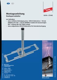
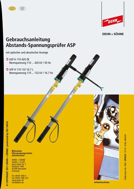
<strong>Gebrauchsanleitung</strong><br />
<strong>Abstands</strong>-<strong>Spannungsprüfer</strong> <strong>ASP</strong><br />
mit optischer und akustischer Anzeige<br />
<strong>ASP</strong> A 110 420 ZK<br />
Nennspannung 110 ... 420 kV / 50 Hz<br />
<strong>ASP</strong> A 110 132 16.7 L<br />
Nennspannung 110 ... 132 kV / 16.7 Hz<br />
© COPYRIGHT 2011 <strong>DEHN</strong> + SÖHNE / protected by ISO 16016<br />
Blitzschutz<br />
Überspannungsschutz<br />
Arbeitsschutz<br />
<strong>DEHN</strong> + SÖHNE<br />
GmbH + Co.KG.<br />
Hans-Dehn-Str. 1<br />
Postfach 1640<br />
92306 Neumarkt<br />
Germany<br />
Tel. 09181 906-0<br />
Fax 09181 906-333<br />
www.dehn.de<br />
info@dehn.de<br />
Arbeitsschutz<br />
Publication No. 1665 UPDATE 11.11 Id No. 064330
Inhaltsverzeichnis<br />
Besondere Sicherheitshinweise ................................................................................................................3<br />
1. Allgemeine Anwendungsbestimmungen....................................................................................4<br />
1.1 Normhinweise.......................................................................................................................4<br />
1.2 Nennspannung .....................................................................................................................4<br />
1.3 Sicherheitsabstände von Anlagenteilen ................................................................................4<br />
1.4 Witterungsbedingungen .......................................................................................................4<br />
1.5 Zustimmung zur Anwendung...................................... ..........................................................4<br />
2. Hinweise für die Benutzung.........................................................................................................5<br />
2.1 Überprüfung der Einzelteile ..................................................................................................5<br />
2.2 Defekte Einzelteile................................................................................................................5<br />
2.3 Verschmutzte Einzelteile.......................................................................................................5<br />
2.4 Betaute, feuchte Einzelteile...................................................................................................5<br />
2.5 Zulässige Komponenten........................................................................................................5<br />
2.6 Einsatz in Freileitungen.........................................................................................................5<br />
2.7 Einsatz in Freiluftanlagen......................................................................................................5<br />
2.8 Eigenprüfung (Funktionsprüfung) .........................................................................................5<br />
2.9 Hinweis zur Handhabe..........................................................................................................5<br />
2.10 Sicherheitsabstand................................................................................................................5<br />
2.11 Allpolige Prüfung auf Spannungsfreiheit ..............................................................................5<br />
2.12 Klimaklasse N, Temperatur- und Luftfeuchtebereich .............................................................5<br />
2.13 Transport, Aufbewahrung......................................................................................................5<br />
3. Anwendungshinweise.......................................................................................................... 6<br />
3.1 Funktion und Wirkungsweise ...........................................................................................6<br />
3.1.1 Wirkungsweise des elektrischen Wechselfeldes....................................................................6<br />
3.1.2 Funktionsprinzip der E-Feldmessung.....................................................................................6<br />
3.1.3 Funktionsprinzip des <strong>Abstands</strong>-<strong>Spannungsprüfer</strong> <strong>ASP</strong>......................................................... .7<br />
3.2 Zusammenbau des <strong>Abstands</strong>-<strong>Spannungsprüfer</strong> <strong>ASP</strong> .....................................................9<br />
3.2.1 Sichtprüfung der Einzelteile..................................................................................................9<br />
3.2.2 Montage E-Feldsensor..........................................................................................................9<br />
3.2.3 Montage Isolierstange mit Universialzahnkupplung............................................................10<br />
3.2.4 Montage Handhabeverlängerung ........................................................................................11<br />
3.2.5 Montage Anschlussteil Ringöse ...........................................................................................11<br />
3.2.6 Hinweise zur sicheren Handhabung.....................................................................................11<br />
3.2.7 Nennspannungsbereich .......................................................................................................13<br />
3.2.8 Anzeige Spannung vorhanden .............................................................................................13<br />
3.2.9 Erläuterung zum Typenschild ...............................................................................................13<br />
3.2.10 Eigenprüfung (Selbssttest) des Anzeigegerätes....................................................................14<br />
3.2.11 Elektrische Überprüfungder E-Feldsensoren.........................................................................15<br />
4. Inbetriebnahme und Anwendung ....................................................................................... 15<br />
4.1 Einschalten des Anzeigegerätes...........................................................................................15<br />
4.2 Anwendung Freileitung....................................................................................................16<br />
4.2.1 Zusammenstellung der Gerätekomponenten .......................................................................16<br />
4.2.2 Prüfvorgang bei Freileitung..................................................................................................16<br />
4.3 Anwendung Freiluftschaltanlage....................................................................................18<br />
4.3.1 Zusammenstellung der Gerätekomponenten .......................................................................18<br />
4.3.2 Prüfvorgang in Freiluftschaltanlagen ...................................................................................18<br />
5. Batteriewechsel Anzeigegerät <strong>ASP</strong> A 110 ... ..................................................................... 20<br />
6. Wiederholungsprüfung................................................................................................................22<br />
8. Reinigung und Pflege...................................................................................................................22<br />
8. Transport und Aufbewahrung .....................................................................................................23<br />
8.1 Transport..............................................................................................................................23<br />
8.2 Aufbewahrung.....................................................................................................................24<br />
8.3 Schutz vor UV-Strahlung......................................................................................................24<br />
9. Austauschteile ..............................................................................................................................24<br />
10. Beschädigungen ...........................................................................................................................24<br />
11. Normbezüge ....................................................................................................................... 24<br />
Seite 2
Besondere Sicherheitshinweise<br />
Der <strong>Abstands</strong>-<strong>Spannungsprüfer</strong> <strong>ASP</strong> darf nur von einer Elektrofachkraft oder einer<br />
elektrotechnisch unterwiesenen Person im Sinne von DIN VDE 0105-100: ... (EN 50110-1:<br />
...) benutzt werden – sonst besteht Lebensgefahr!<br />
Der <strong>Abstands</strong>-<strong>Spannungsprüfer</strong> <strong>ASP</strong> darf nur eingesetzt werden, wenn die<br />
Sicherheitsvorkehrungen gegen Brand- und Explosionsgefahren berücksichtigt<br />
wurden (siehe B2 und B3 in DIN VDE 0105-100: ... (EN 50110-1: ...)).<br />
Vor dem Einsatz ist der <strong>Abstands</strong>-<strong>Spannungsprüfer</strong> <strong>ASP</strong> auf ordnungsgemäßen<br />
Zustand zu kontrollieren. Sollte eine Beschädigung oder ein sonstiger Mangel<br />
festgestellt werden, darf der <strong>Abstands</strong>-<strong>Spannungsprüfer</strong> <strong>ASP</strong> nicht eingesetzt<br />
werden.<br />
Der Einsatz des <strong>Abstands</strong>-<strong>Spannungsprüfer</strong>s <strong>ASP</strong> ist grundsätzlich nur im Rahmen der<br />
in dieser <strong>Gebrauchsanleitung</strong> genannten Vorgaben und Bedingungen zulässig.<br />
Wird nur einer der angeführten Sicherheitshinweise nicht berücksichtigt oder<br />
missachtet, besteht Gefahr für Leib und Leben des Anwenders, außerdem ist die<br />
Anlagenverfügbarkeit gefährdet.<br />
Eingriffe oder Veränderungen an dem <strong>Abstands</strong>-<strong>Spannungsprüfer</strong> <strong>ASP</strong> oder das<br />
Hinzufügen fabrikat- oder typfremder Komponenten gefährden die Arbeitssicherheit,<br />
sind unzulässig und führen zum Erlöschen des Gewährleistungsanspruches.<br />
Seite 3
1. Allgemeine Anwendungsbestimmungen<br />
1.1 Bei der Anwendung des <strong>Abstands</strong>-<strong>Spannungsprüfer</strong> <strong>ASP</strong> ist die DIN VDE 0105-100 zu<br />
beachten.<br />
1.2 Der <strong>Abstands</strong>-<strong>Spannungsprüfer</strong> darf nur im Bereich der gleichen Nenndaten<br />
(z.B. Nennspannung / Nennfrequenz), welche auf dem jeweiligen Typenschild<br />
(Anlage / <strong>Abstands</strong>-<strong>Spannungsprüfer</strong>) ausgewiesen sind eingesetzt werden.<br />
<br />
<br />
<strong>ASP</strong> A 110 420 ZK<br />
Nennspannung 110 ... 420 kV / 50 Hz<br />
Der <strong>Abstands</strong>-<strong>Spannungsprüfer</strong> darf nur in Freileitungen und in Freiluftschaltanlagen<br />
verwendet werden.<br />
<strong>ASP</strong> A 110 132 16.7 L<br />
Nennspannung 110...132 kV / 16,7 Hz, für mittig geerdete Einphasensysteme<br />
Der <strong>Abstands</strong>-<strong>Spannungsprüfer</strong> darf nur in Freileitungen verwendet werden.<br />
1.3 Der <strong>Abstands</strong>-<strong>Spannungsprüfer</strong> <strong>ASP</strong> darf beim Prüfen auf Spannungsfreiheit nur<br />
an der Handhabe seiner Isolierstange gefasst und von einem sicheren Standort<br />
aus an den Anlegepunkt (siehe Pkt 4.2.2 bzw 4.3.2) geführt werden.<br />
Der Monteur sowie der Feldsensor des <strong>Abstands</strong>-<strong>Spannungsprüfer</strong>s <strong>ASP</strong> müssen<br />
dabei im notwendigen Sicherheitsabstand von unter Spannung stehenden<br />
Anlageteilen entfernt sein.<br />
1.4 Der <strong>Abstands</strong>-<strong>Spannungsprüfer</strong> <strong>ASP</strong> darf bei allen Witterungsbedingungen<br />
eingesetzt werden.<br />
1.5 Der Benutzer des <strong>Abstands</strong>-<strong>Spannungsprüfer</strong> <strong>ASP</strong> muss sich beim Betreiber der<br />
elektrischen Anlage die Zustimmung zur Anwendung des <strong>ASP</strong> einholen.<br />
Seite 4
2. Hinweise für die Benutzung<br />
Bei der Anwendung sind nachfolgende Punkte unbedingt zu beachten:<br />
2.1 Der <strong>Abstands</strong>-<strong>Spannungsprüfer</strong> <strong>ASP</strong> bestehend aus E-Feldsensor, Anzeigegerät<br />
und Isolierstange. Die Einzelteile sind vor der Anwendung einer Sichtprüfung auf<br />
mechanische Schäden zu unterziehen.<br />
2.2 Defekte Einzelteile sind aus Sicherheitsgründen der Weiterverwendung zu<br />
entziehen.<br />
2.3 Verschmutze Einzelteile sind vor der Anwendung (vor den Zusammenbau) mit<br />
einem sauberen, fusselfreien Tuch zu reinigen.<br />
2.4 Betaute, feuchte Einzelteile (z.B.: hervorgerufen durch extreme Temperaturschwankungen)<br />
sind vor der Anwendung trocken zu wischen, gegebenenfalls ist abzuwarten bis die<br />
Komponenten die Umgebungstemperatur angenommen haben.<br />
2.5 Das Anzeigegerät, Typ <strong>ASP</strong> A 110... .... .. darf nur mit dem am Typenschild<br />
aufgeführten E-Feldsensoren und Isolierstangen, verwendet werden.<br />
2.6 Der <strong>Abstands</strong>-<strong>Spannungsprüfer</strong> <strong>ASP</strong> darf an Freileitungen nur mit den am<br />
Typenschild aufgeführten E-Feldsensor Kategorie L und der Isolierstange mit<br />
Handschlaufe verwendet werden.<br />
2.7 Der <strong>Abstands</strong>-<strong>Spannungsprüfer</strong> <strong>ASP</strong> darf in Freiluftschaltanlagen nur mit den am<br />
Typenschild aufgeführten E-Feldsensor Kategorie S und einer der am Typenschild<br />
aufgeführten Isolierstangen verwendet werden.<br />
2.8 Der <strong>Abstands</strong>-<strong>Spannungsprüfer</strong> <strong>ASP</strong> ist unmittelbar vor und nach der Anwendung<br />
auf seine Funktion zu Prüfen (siehe Pkt. 3.2.10, Seite 14).<br />
2.9 Der <strong>Abstands</strong>-<strong>Spannungsprüfer</strong> <strong>ASP</strong> darf beim Prüfen auf Spannungsfreiheit nur an<br />
der Handhabe der Isolierstange gefasst werden.<br />
2.10 Beim Prüfvorgang ist auf einen sicheren Standort zu achten.<br />
2.11 Die Prüfung auf Spannungsfreiheit muss an der Arbeitsstelle allpolig durchgeführt werden<br />
(siehe Anwendungsbeispiele, Seite 17 und 19).<br />
2.12 Beim Prüfen auf Spannungsfreiheit sind die der Klimaklasse N entsprechenden<br />
Grenzwerte - 25°C bis +55°C (Temperaturbereich) und 20% bis 96% (relative<br />
Feuchte), einzuhalten.<br />
2.13 Der <strong>Abstands</strong>-<strong>Spannungsprüfer</strong> <strong>ASP</strong> und Zubehörteile sind in seiner Transporttasche<br />
(siehe Pkt. 8, Seite 23) zu transportieren und aufzuwahren, vor Verschmutzung zu<br />
schützen.<br />
Beim Transport und Lagerung ist der Temperaturbereich – 25°C bis +70°C sowie<br />
die Grenzwerte der relativen Luftfeuchte 20% bis 70% zu beachten.<br />
Seite 5
3. Anwendungshinweise<br />
3.1 Funktion und Wirkungsweise<br />
3.1.1 Wirkungsweise des elektrischen<br />
Wechselfeldes<br />
Zwischen zwei oder mehreren Elektroden,<br />
die sich auf unterschiedlichem Potential<br />
befinden, bildet sich ein elektrisches Feld<br />
aus (siehe Bild 3.1.1). Das elektrische<br />
Feld kann durch Äquipotentiallinien und<br />
die darauf senkrecht stehenden Feldlinien<br />
beschrieben werden.<br />
Die elektrische Feldstärke an einem bestimmten<br />
Punkt in der Umgebung einer<br />
elektrotechnischen Anlage hängt von der<br />
Höhe der Spannung an den Elektroden<br />
und von deren geometrischen Anordnung<br />
ab (siehe Bild 3.1.1).<br />
E-Feldlinien<br />
Isolator<br />
Leiter<br />
Bild 3.1.1 Prinzipielle Darstellung<br />
des E-Feldes<br />
3.1.2 Funktionsprinzip der E-Feldmessung<br />
Zwischen dem unter Spannung stehenden<br />
Anlagenteil (L), den beiden Elektroden E1<br />
und E2 des <strong>Abstands</strong>-<strong>Spannungsprüfer</strong>s<br />
<strong>ASP</strong> sowie der Erde, wirken Teilkapazitäten,<br />
wie in Bild 3.1.2 dargestellt.<br />
Da der ohmsche Eingangswiderstand RE<br />
gegenüber den Wechselstromwiderständen<br />
der Kapazitäten klein ist, wird der<br />
Eingangsstrom IE insbesondere von<br />
der Reihenschaltung CL1 (Phasenkapazität)<br />
und CE2 (Erdkapazität) bestimmt.<br />
Die Kapazitäten CL2 und CE1 wirken dabei<br />
als Nebenschlüsse (siehe Bild 3.1.2).<br />
L<br />
C L1<br />
C L2<br />
E1<br />
RE<br />
IE<br />
E2<br />
C E1 C E2<br />
Bild 3.1.2 Prinzipielle Darstellung<br />
der E-Feldmessung<br />
Seite 6
3.1.3 Funktionsprinzip des <strong>Abstands</strong>-<strong>Spannungsprüfer</strong> <strong>ASP</strong><br />
Wird der <strong>Abstands</strong>-<strong>Spannungsprüfer</strong> <strong>ASP</strong> in ein solches elektrisches Wechselfeld gebracht (siehe<br />
Bild 3.1.3a, APS, Freiluftschaltanlagen und Bild 3.1.3b, Seite 8, <strong>ASP</strong> an Freileitung) so fließt über<br />
die Messelektroden E1 (E-Feldsensor) ein Eingangsstrom IE, der in der nachgeschalteten<br />
Elektronik (Anzeigegerät) weiter verarbeitet wird. Übersteigt der Eingangsstrom IE einen<br />
bestimmten Sollwert, so gibt der <strong>Abstands</strong>-<strong>Spannungsprüfer</strong> <strong>ASP</strong> ein intermittierendes<br />
optisches (LED Rot) und akustische Signal (Ton) ab.<br />
z.B. Schaltanlagen 110 kV<br />
z.B. Schaltanlagen 110 kV<br />
mit Blitzschutzamatur<br />
Isolator<br />
90°<br />
Leiterseil<br />
Bügel<br />
90°<br />
Blitzschutzamatur<br />
Leiterseil<br />
Bügel<br />
E1<br />
Elektrode<br />
E-Feldsensor<br />
E2<br />
Elektrode<br />
Anzeigegerät<br />
<strong>ASP</strong><br />
L<br />
C L1<br />
C L2<br />
E1<br />
RE IE<br />
E2<br />
C E1 C E2<br />
Bild 3.1.3a Anwendung Freiluftschaltanlagen<br />
Seite 7
z.B. Freileitung 220 kV mit Blitzschutzamatur<br />
Blitzschutzamatur<br />
Elektrode<br />
Anzeigegerät<br />
<strong>ASP</strong><br />
E2<br />
RE<br />
C E1 C E2<br />
C L2<br />
E2<br />
IE<br />
Elektrode<br />
E-Feldsensor<br />
E1<br />
C L1<br />
E1<br />
Isolator<br />
L<br />
Leiterseil<br />
Bild 3.1.3b Anwendung Freileitung<br />
Seite 8
3.2 Zusammenbau des <strong>Abstands</strong>-<strong>Spannungsprüfer</strong><br />
<strong>ASP</strong><br />
Dichtring<br />
3.2.1 Sichtprüfung der Einzelteile vor dem<br />
Zusammenbau<br />
- E-Feldsensor, Anzeigegerät und Isolierstange<br />
sind auf mechanische Schäden zu überprüfen.<br />
- Teile mit erkennbaren Schäden wie z.B. Risse,<br />
Verformungen, abgebrochenen Anbauten<br />
sowie nicht mehr erkennbarer Aufschriften, sind<br />
der Weiterverwendung zu entziehen.<br />
- Verschmutzte Einzelteile sind vor der Montage<br />
zu Reinigen (siehe Pkt. 7, Seite 22).<br />
- Der Dichtring am E-Feldsensor, EFS L 127 oder<br />
EFS S 167 ist vor dem Aufschrauben auf das<br />
Anzeigegerät zu überprüfen. Ein poröser oder<br />
lose sitzender Dichtring ist auszutauschen<br />
(siehe Bild 3.2.1 (siehe hierzu auch Pkt. 9<br />
Seite 24)).<br />
3.2.2 Montage E-Feldsensor<br />
Bild 3.2.1<br />
E-Feldsensor<br />
EFS L 127<br />
E-Feldsensor<br />
EFS S 167<br />
E-Feldsensor für Freiluftschaltanlagen<br />
E- Field sensor for outdoor substations<br />
Kategorie/Category: "S"<br />
Fert.-Nr. Jahr Letzte Wiederh.-Prüfg.<br />
Prod.-No. Year Last repeat test<br />
EFS S 167<br />
767 577<br />
- Der E-Feldsensor EFS L 127 oder EFS S 167 ist auf das<br />
Anzeigegerät aufzusetzen und mittels Rechtsdrehung<br />
aufzuschrauben (siehe Bild 3.2.2).<br />
- Der Feldsensor ist bis zum Anschlag einzuschrauben.<br />
- Der Gehäuserand des Anzeigegerätes muss dabei vom<br />
E-Feldsensor um ca. 2 mm überdeckt werden.<br />
<strong>Abstands</strong>spannungsprüfer<br />
Non-contact Voltage Detector<br />
110...420 KV / 50 Hz<br />
<strong>ASP</strong><br />
Unter Spannung stehendeTeile nicht berühren /<br />
Do not touch any live parts<br />
E-Feldsensor / E-Field sensor<br />
Kategorie/Category "L": EFS L 127<br />
Kategorie/Category "S": EFS L 167<br />
Isolierstange / Insulating rod<br />
- IS ZK STK HS 670<br />
- IS ZK STK 670<br />
Klimaklasse: / Climatic category: N<br />
Anzeigegerät<br />
<strong>ASP</strong> A 110 420 ZK<br />
Anzeigegerät / Indicator<br />
<strong>ASP</strong> A 110 420 ZK<br />
767 570<br />
Seite 9<br />
Bild 3.2.2
3.2.3 Montage Isolierstange mit<br />
Universalzahnkupplung<br />
Anzeigegerät <strong>ASP</strong><br />
mit E-Feldsensor<br />
- Zur Montage und Demontage<br />
der Isolierstange auf das Anzeigegerät<br />
muss die Rändelschraube<br />
der Isolierstange<br />
komplett herausgeschraubt<br />
werden (siehe Bild 3.2.3).<br />
- Für die Anwendung Freileitung,<br />
von der Masttraverse aus, ist die<br />
Isolierstange, IS ZK STK HS 670<br />
mit Handschlaufe zu montieren.<br />
Handhabeverlängerung<br />
Handhabe<br />
HV STK 710 Isolierstange<br />
IS ZK STK HS 670<br />
Universalzahnkupplung<br />
(Rändelschraube)<br />
Handhabeverlängerung<br />
(Steckkupplung)<br />
- Zum Ausrichten des Anzeigegerätes<br />
beim Anlegen an die<br />
erdseitige Blitzschutzarmatur<br />
von der Masttraverse aus kann<br />
das Anzeigegerät an der Isolierstange<br />
abgewinkelt werden.<br />
Die geschlossene Zahnkupplung<br />
am Anzeigegerät verhindert beim<br />
Lösen der Rändelschraube zum<br />
Abwinkeln der Isolierstange ein<br />
Abstürzen des Anzeigegerätes.<br />
– Für die Anwendung in der Freiluftschaltanlage<br />
darf auch die<br />
Isolierstange, IS ZK STK 670<br />
ohne Handschlaufe montiert<br />
werden.<br />
– Grundsätzlich ist vor der Anwendung<br />
die Verschraubung der<br />
Zahnkupplung auf ihren<br />
festen Sitz zu überprüfen.<br />
Bild 3.2.3 Montage Isolierstange<br />
Seite 10
3.2.4 Montage Handhabeverlängerung<br />
– Zur Handhabeverlängerung sind die Isolierstangen,<br />
IS ZK STK HS 670, IS ZK STK 670 am Ende der Handhabe<br />
mit einer Kunststoff-Steckkupplung ausgerüstet (siehe Bild<br />
3.2.3, Seite 10).<br />
– Als Handhabeverlängerung können alle Handhabeverlängerungen<br />
mit Kunststoff-Steckkupplung aus den Dehn-Lieferprogramm<br />
eingesetzt werden. Dabei darf die maximale<br />
Länge LG max von 3500 mm nicht überschritten werden.<br />
– Die Handhabeverlängerung wird beim Einsatz des <strong>Abstands</strong>-<br />
<strong>Spannungsprüfer</strong> <strong>ASP</strong> in der Freiluftschaltanlage zum Erreichen<br />
des Anlegepunktes benötigt.<br />
3.2.5 Montage Abschlussteil Ringöse<br />
1<br />
2<br />
3<br />
E-Feldsensor<br />
EFS L 127<br />
Anlegemarke<br />
(Grüner Ring)<br />
– Das Abschlussteil mit Ringöse, AR STK ist am Ende der<br />
Handhabe durch einfaches Aufstecken zu montieren<br />
(siehe Bild 3.2.6a).<br />
– Das Abschlussteil Ringöse wird beim Einsatz des <strong>Abstands</strong>-<br />
<strong>Spannungsprüfer</strong> <strong>ASP</strong> an Freileitungen beim Mastaufstieg<br />
zum Einhängen am Karabiner des Geschirrs empfohlen.<br />
L I<br />
405 mm<br />
L G<br />
960 mm<br />
3.2.6 Hinweise zur sicheren Handhabung<br />
– Der <strong>Abstands</strong>-<strong>Spannungsprüfer</strong> <strong>ASP</strong> darf beim Prüfen auf<br />
Spannungsfreiheit nur an der Handhabe seiner Isolierstange<br />
bis zur Begrenzungsscheibe gefasst werden.<br />
– Ein Übergreifen der Begrenzungsscheibe ist während des<br />
Prüfvorganges nicht erlaubt.<br />
– Mit den E-Feldsensor des <strong>Abstands</strong>-<strong>Spannungsprüfer</strong> darf<br />
kein aktives, unter Spannung stehendes Anlagenteil, berührt<br />
werden (siehe Bild 3.2.6a und 3.2.6b, Seite 12).<br />
4<br />
5<br />
L H<br />
264 mm<br />
6<br />
Legende zu Bild 3.2.6a<br />
L G Gesamtlänge des <strong>Abstands</strong>-<strong>Spannungsprüfer</strong>s <strong>ASP</strong><br />
L I Länge des Isolierteils<br />
L H Länge der Handhabe<br />
1 E-Feldsensor EFS L 127<br />
2 Anzeigegerät <strong>ASP</strong> A 110 420 ZK / <strong>ASP</strong> A 110 132 16.7 L<br />
3 Anlegemarke (Grüner Ring)<br />
4 Isolierteil<br />
5 Begrenzungsscheibe<br />
6 Handhabe<br />
7 Ringöse AR STK<br />
Seite 11<br />
7<br />
Bild 3.2.6a<br />
150 mm<br />
<strong>Abstands</strong>-<strong>Spannungsprüfer</strong><br />
<strong>ASP</strong> für Freileitung
1<br />
E-Feldsensor<br />
EFS S 167<br />
3<br />
Ausleger<br />
2<br />
Anlegemarke<br />
(Grüne Gabel)<br />
L I<br />
405 mm<br />
L G<br />
1000 mm<br />
4<br />
5<br />
L H<br />
264 mm<br />
Legende zu Bild 3.2.6b<br />
L G Gesamtlänge des <strong>Abstands</strong>-<strong>Spannungsprüfer</strong>s <strong>ASP</strong><br />
L I Länge des Isolierteils<br />
L H Länge der Handhabe<br />
6<br />
1 E-Feldsensor EFS S 167<br />
2 Anzeigegerät <strong>ASP</strong> A 110 420 ZK / <strong>ASP</strong> A 110 132 16.7 L<br />
3 Ausleger mit grüner Gabel (Anlegemarke)<br />
4 Isolierteil<br />
5 Begrenzungsscheibe<br />
6 Handhabe<br />
Bild 3.2.6b<br />
<strong>Abstands</strong>-<strong>Spannungsprüfer</strong><br />
<strong>ASP</strong> für Freiluftschaltanlagen<br />
Seite 12
3.2.7 Nennspannungsbereich<br />
– Der <strong>Abstands</strong>-<strong>Spannungsprüfer</strong> <strong>ASP</strong> ist in seinen Ansprechverhalten für den Nennspannungsbereich<br />
ausgelegt:<br />
<strong>ASP</strong> A 110 420 ZK, Un = 110 bis 420 kV / 50 Hz<br />
<strong>ASP</strong> A 110 132 16.7 L , Un = 110 bis 132 kV / 16,7 Hz, für mittig geerdete Einphasensysteme<br />
– Der <strong>Abstands</strong>-<strong>Spannungsprüfer</strong> <strong>ASP</strong> darf nur in den am Typenschild aufgeführten<br />
Nennspannungsbereich und Nennfrequenz verwendet werden<br />
3.2.8 Anzeige Spannung Vorhanden<br />
Die Anzeige “Spannung vorhanden”<br />
wird bei einer Leiter-Erdspannung<br />
> 45 % der Nennspannung durch die<br />
blinkende LED Rot und ein<br />
intermittierendes Tonsignal signalisiert<br />
(siehe Bild 3.2.8).<br />
3.2.9 Erläuterung zum Typenschild<br />
Taste "Test"<br />
LED Rot<br />
LED Grün<br />
Austrittsöffnung<br />
für akustisches<br />
Tonsignal<br />
Der <strong>Abstands</strong>-<strong>Spannungsprüfer</strong> <strong>ASP</strong> darf<br />
nur mit den am Typendschild des<br />
Anzeigegerätes, <strong>ASP</strong> A 110 420 ZK<br />
Bild 3.2.8<br />
bzw. <strong>ASP</strong> A 110 132 16.7 L<br />
aufgeführten Komponenten verwendet werden (siehe hierzu nachfolgende Auflistung und<br />
Typenschilder):<br />
- E-Feldsensor, Typ EFS L 127 in der Freileitung<br />
- E-Feldsensor, Typ EFS S 167 in Freiluftschaltanlagen<br />
- Isolierstange, Typ IS ZK STK HS 670 in der Freileitung und in Freiluftschaltanlagen<br />
- Isolierstange, Typ IS ZK STK 670 in Freiluftschaltanlagen<br />
Anmerkung:<br />
Ausgenommen davon sind nachfolgende Handhabeverlängerungen aus dem<br />
<strong>DEHN</strong> + SÖHNE Programm: HV STK 30 710, HV STK 43 910 und HV STK 43 1280.<br />
<strong>Abstands</strong>spannungsprüfer<br />
Non-contact Voltage Detector<br />
110...420 KV / 50 Hz<br />
Unter Spannung stehendeTeile nicht berühren /<br />
Do not touch any live parts<br />
E-Feldsensor / E-Field sensor<br />
Kategorie/Category "L": EFS L 127<br />
Kategorie/Category "S": EFS S 167<br />
Isolierstange / Insulating rod<br />
- IS ZK STK HS 670<br />
- IS ZK STK 670<br />
Klimaklasse: / Climatic category: N<br />
Anzeigegerät / Indicator<br />
<strong>ASP</strong> A 110 420 ZK<br />
767 570<br />
Handhabeverlängerung<br />
Handle extension<br />
Art.No: 766 335<br />
Typ: HV STK 30 710<br />
<strong>ASP</strong><br />
Baujahr/Yaer. 08 09 10 11 12 13<br />
E-Feldsensor für Freiluftschaltanlagen<br />
E- Field sensor for outdoor substations<br />
Kategorie/Category: "S"<br />
F.-Nr. Jahr Letzte Wiederh.-Prüfg.<br />
Prod.-No. Year Last repeat test<br />
EFS S 167<br />
767 577<br />
E-Feldsensor für Freileitung<br />
E- Field sensor for Overhead lines<br />
Kategorie/Category: "L"<br />
F.-Nr. Jahr Letzte Wiederh.-Prüfg.<br />
Prod.-No. Year Last repeat test<br />
EFS L 127<br />
767 576<br />
Isolierstange<br />
Insulating rod<br />
F.-Nr. Jahr Letzte Wiederh.-Prüfg.<br />
Prod.-No. Year Last repeat test<br />
IS ZK STK HS 670<br />
766 369<br />
Isolierstange<br />
Insulating rod<br />
F.-Nr. Jahr Letzte Wiederh.-Prüfg.<br />
Prod.-No. Year Last repeat test<br />
IS ZK STK 670<br />
766 368<br />
Seite 13
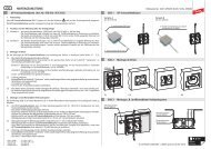
3.2.10 Eigenprüfung (Selbsttest) des Anzeigegerätes<br />
- Das Anzeigegerät ist mit einer zwangsweisen Eigenprüfung ausgestattet.<br />
- Bei jedem Einschaltvorgang des Anzeigegerätes durch das Drücken der Taste “Test” wird<br />
die Eigenprüfung gestartet.<br />
- Die Eigenprüfung überprüft die Funktion des Messkreises, die Ansprechschwelle, die Anzeigen<br />
und den Zustand der Batterieversorgung.<br />
- So lange die Taste “Test” gedrückt wird, blinkt die LED Rot und es ertönt ein intermittierender<br />
Signalton in der gleichen Taktfrequenz.<br />
- Beim Loslassen der Taste “Test” muss die LED Grün aufleuchten. Dabei erlischt die LED<br />
Rot und das Tonsignal verstummt.<br />
- Die LED Grün signalisiert die positiv abgeschlossene Eigenprüfung (Selbsttest) und die<br />
Betriebsbereitschaft des Anzeigegerätes für ca. 120 sec.<br />
- Eine erschöpfter Batterie signalisiert das Anzeigegerät durch einen Dauerton und die<br />
Daueranzeige der LED Rot und LED Grün (siehe Bild 3.2.10 sowie Tabelle 1).<br />
Taste "Test"<br />
LED Rot<br />
Bild 3.2.10<br />
LED Grün<br />
Austrittsöffnung<br />
für akustisches<br />
Tonsignal<br />
Anmerkung:<br />
Die Anzeige des<br />
Anzeigegerätes <strong>ASP</strong> A 110<br />
... . ist nur dann eindeutig,<br />
wenn eine der beiden LED-Anzeigen<br />
leuchtet. Mit der roten<br />
LED muss auch das intermittierende<br />
akustische Signal<br />
ertönen.<br />
Anzeige<br />
Spannungs-/Betriebszustand<br />
grüne LED zeigt Dauerlicht<br />
Spannung nicht vorhanden (Betriebsbereit)<br />
rote LED zeigt Blinklicht und das<br />
intermittierende akustische Signal ertönt<br />
Spannung vorhanden<br />
keine Anzeigenlampe leuchtet Eigenprüfung (nach Pkt. 3.2.10)<br />
nicht durchgeführt<br />
grüne und rote LED's leuchten<br />
Batterie ist erschöpft<br />
gleichzeitig und ein Dauerton ertönt (Batterie wechseln nach Pkt. 5, Seite 20)<br />
Tabelle 1 Bedeutung der Anzeigensignale<br />
Seite 14
3.2.11 Elektrische Überprüfung der E-Feldsensoren<br />
- Die beiden E-Feldsensoren sind nicht in die zwangsweise Eigenprüfung bei jeden<br />
Einschalten des Anzeigegerätes eingebunden.<br />
- Eine elektrische Überprüfung der E-Feldsensoren ist durch eine einfache<br />
Durchgangsprüfung möglich (siehe Bild 3.2.11).<br />
- Dabei müssen die beiden<br />
E-Feldsensoren folgende<br />
Innenwiderstände aufweisen:<br />
E-Feldsensor, EFS L 127<br />
Messwert: ca. 10 Ohm<br />
E-Feldsensor, EFS S 167<br />
Messwert: ca. 100 Ohm<br />
Messpunkt:<br />
an der metallischen<br />
Kappenverschraubung<br />
- Ein elektrische Überprüfung<br />
der E-Feldsensoren vor jeder<br />
Anwendung ist nicht notwendig<br />
(siehe Bild 3.2.11).<br />
Messpunkt:<br />
an der metallischen<br />
Gewindebuchse<br />
4. Inbetriebnahme und Anwendung<br />
4.1 Einschalten des Anzeigegerätes<br />
Bild 3.2.11 Funktionsprüfung am E-Feldsensor<br />
- Mit dem Einschalten des Anzeigegerätes, durch Drücken der Taste “Test”, wird automatisch<br />
die Eigenprüfung (Selbsttest) gestartet.<br />
- So lange die Taste “Test” gedrückt wird blinkt die LED Rot und ertönt ein intermittierendes<br />
Ton-Signal.<br />
- Beim Loslassen der Taste “Test” leuchtet die LED Grün auf.<br />
Die LED Grün signalisiert die positiv abgeschlossene Eigenprüfung (Selbsttest) und die<br />
Betriebsbereitschaft des Anzeigegerätes für ca. 120 sec.<br />
- Während des Prüfvorganges wird mit der Anzeige “Spannung vorhanden” automatisch die<br />
Betriebsbereitschaft für ca. 120 sec. verlängert (siehe Bild 4.1).<br />
Taste "Test"<br />
LED Rot<br />
LED Grün<br />
Austrittsöffnung<br />
für akustisches<br />
Tonsignal<br />
Anmerkung:<br />
Die Anzeige des Anzeigegerätes<br />
<strong>ASP</strong> A 110 ... .. ist nur<br />
dann eindeutig, wenn eine der<br />
beiden LED-Anzeigen leuchtet.<br />
Mit der roten LED muss auch das<br />
intermittierende akustische<br />
Signal ertönen.<br />
Bild 4.1<br />
Seite 15
4.2 Anwendung Freileitung<br />
4.2.1 Zusammenstellung der Gerätekomponenten<br />
- Das Anzeigegerät <strong>ASP</strong> A 110 420 ZK /<br />
<strong>ASP</strong> A 110 132 16.7 L ist mit dem<br />
E-Feldsensor, EFS L 127 und der Isolierstange,<br />
IS ZK STK HS 670 mit Handschlaufe zu montieren.<br />
- Zum Mastaufsteigen empfiehlt es sich das<br />
Abschlussteil, Ringöse, AR STK am Ende der<br />
Handhabe zu montieren.<br />
Der <strong>Abstands</strong>-<strong>Spannungsprüfer</strong> <strong>ASP</strong> kann damit<br />
einfach und sicher am Karabiner des Geschirres<br />
eingehängt werden (siehe Bild 4.2.1).<br />
4.2.2 Prüfvorgang bei Freileitung<br />
- Vor dem Prüfvorgang ist der <strong>Abstands</strong>-<br />
<strong>Spannungsprüfer</strong> durch Drücken der Taste “Test”<br />
einzuschalten.<br />
Beim Loslassen der Taste "Test" muss die LED<br />
Grün leuchten (siehe Bild 4.2.2a).<br />
Taste "Test"<br />
LED Grün<br />
Anzeigegerät<br />
<strong>ASP</strong> A 110 ...<br />
Isolierstange<br />
IS ZK STK HS 670<br />
E-Feldsensor<br />
EFS L 127<br />
LED Rot<br />
Austrittsöffnung<br />
für akustisches<br />
Tonsignal<br />
Bild 4.2.2a<br />
Handhabe<br />
Abschlussteil<br />
Ringöse STK<br />
AR STK<br />
Handschlaufe<br />
Bild 4.2.1<br />
Seite 16
- Zum Prüfen auf Spannungsfreiheit muss das Anzeigegerät direkt auf die erdseitige<br />
Blitzschutzarmatur (Anlegepunkt) unmittelbar vor dem “Grünen Ring” des Anzeigegerätes<br />
aufgelegt werden.<br />
- Der E-Feldsensor EFS L 127 muss dabei parallel zur Isolatorkettenachse in Richtung des<br />
zu prüfenden Leiterseiles ausgerichtet werden (siehe Bild 4.2.2b).<br />
- Die Prüfung auf “Spannungsfreiheit” muss allpolig durchgeführt werden.<br />
- Der Betriebszustand “Spannung vorhanden” wird optisch, durch eine blinkende LED Rot<br />
und akustisch durch ein intermittierendes Tonsignal angezeigt.<br />
- Der Betriebszustand “spannungsfrei” wird optisch durch die LED Grün angezeigt.<br />
- Erlischt während des Positionswechsel die LED Grün “Betriebsbereitschaft”, so muss das<br />
Anzeigegerät, erneut durch Drücken der Taste “Test” eingeschaltet werden (siehe Bild<br />
4.2.2a).<br />
- Die Eigenprüfung des Anzeigegerätes muss vor und nach den Prüfvorgang auf “Spannungsfreiheit”<br />
durchgeführt werden. (siehe Bild 3.2.10, Seite 14).<br />
Anmerkung:<br />
An Abspannketten kann zur Ausrichtung des <strong>Abstands</strong>-<strong>Spannungsprüfer</strong>s <strong>ASP</strong> das<br />
Anzeigegerät mit Hilfe der Zahnkupplung abgewinkelt werden.<br />
z.B. Freileitung<br />
geerdete<br />
Schutzamatur<br />
Isolator<br />
Leiterseil<br />
Bild 4.2.2b Anwendung Freileitung<br />
Seite 17
4.3 Anwendung Freiluftschaltanlage<br />
4.3.1 Zusammenstellung der Gerätekomponenten<br />
Handhabeverlängerung HV STK 30 710 E-Feldsensor EFS S 167<br />
Anzeigegerät<br />
<strong>ASP</strong> A 110 420 ZK<br />
Isolierstange<br />
IS ZK STK HS 670<br />
Handschlaufe<br />
- Das Anzeigegerät, <strong>ASP</strong> A 110 420 ZK ist mit dem<br />
E-Feldsensor, EFS S 167 und der Isolierstange,<br />
IS ZK STK HS 670 mit Handschlaufe<br />
oder<br />
IS ZK STK 670<br />
ohne Handschlaufe<br />
zu montieren.<br />
– Bei Anlagen mit Nennspannungen 220 kV und 420 kV<br />
muss zum Erreichen der Anlegestelle eine ausreichend lange<br />
Handhabeverlängerung montiert werden. z.B. 220 kV,<br />
2 x HV STK 30 710 (siehe Bild 4.3.1).<br />
4.3.2 Prüfvorgang bei Freiluftschaltanlage<br />
- Vor den Prüfvorgang ist der <strong>Abstands</strong>-<strong>Spannungsprüfer</strong><br />
durch Drücken der Taste “Test” einzuschalten.<br />
Beim Loslassen der Taste Test muss die LED Grün<br />
leuchten (siehe Bild 4.3.2a).<br />
- Der Ausleger am E-Feldsensor ist auszuklappen und in seine<br />
Endstellung einzurasten. Ausleger und Anzeigegerät ergeben<br />
bei einen ordnungsgemäß ausgeklappten Ausleger einen<br />
90°- Winkel (siehe Bild 4.3.1).<br />
- Zum Prüfen auf Spannungsfreiheit muss die grün gekennzeichnete<br />
Gabel am Ende des ausgestellten Auslegers direkt<br />
an den ersten erdseitigen Isolatorteller (Anlegepunkt)<br />
angelegt werden (siehe Bild 4.3.2b, Seite 19).<br />
- Bei einer vorhandenen erdseitigen Blitzschutzarmatur ist die<br />
grün gekennzeichnete Gabel am Ende des Auslegers direkt<br />
an den nächsten Isolatorteller oberhalb der Blitzschutzarmatur<br />
anzulegen (siehe Bild 4.3.2b, Seite 19).<br />
Taste "Test"<br />
LED Grün<br />
LED Rot<br />
Austrittsöffnung<br />
für akustisches<br />
Tonsignal<br />
Bild 4.3.1<br />
Seite 18<br />
Bild 4.3.2a
- Der <strong>Abstands</strong>-<strong>Spannungsprüfer</strong> muss parallel zum Stützisolator in Richtung des zu prüfenden<br />
Anlagenteiles ausgerichtet werden. Ausleger und Stützisolator bilden dabei einen<br />
90°-Winkel.<br />
- Der <strong>Abstands</strong>-<strong>Spannungsprüfer</strong> <strong>ASP</strong> ist grundsätzlich nur an festgelegten Positionen<br />
unterhalb der zu erdenden Anlagenteile, wie z.B. unterhalb von Bügelfestpunkten, einzusetzen.<br />
Die Prüfung auf “Spannungsfreiheit” ist grundsätzlich allpolig durchzuführen.<br />
- Der Betriebszustand “Spannung vorhanden” wird optisch, durch eine blinkende LED Rot<br />
und akustisch durch ein intermittierendes Tonsignal angezeigt.<br />
- Der Betriebszustand “spannungsfrei” wird optisch durch die LED Grün angezeigt.<br />
- Erlischt während des Positionswechsel die LED grün “Betriebsbereitschaft”, so muss das<br />
Anzeigegerät erneut durch Drücken der Taste “Test” eingeschaltet werden (siehe Bild<br />
4.3.2a, Seite 18).<br />
- Die Eigenprüfung des Anzeigegerätes muss vor und nach den Prüfvorgang auf<br />
“Spannungsfreiheit” durchgeführt werden (siehe Pkt. 3.2.10, Seite 14).<br />
z.B. Schaltanlagen 110 kV<br />
ohne erdseitiger Schutzarmatur<br />
Leiterseil<br />
Bügel<br />
z.B. Schaltanlagen 110 kV<br />
mit erdseitiger Schutzarmatur<br />
Leiterseil<br />
Bügel<br />
90°<br />
90°<br />
Bild 4.3.2b Anwendung Freiluftschaltanlagen<br />
Seite 19
5. Batteriewechsel Anzeigegerät <strong>ASP</strong> A 110 420 ZK / <strong>ASP</strong> A 110 132 16.7 L<br />
5.1 Durch Linksdrehung des Abschlussrings (4) am unteren Ende des Anzeigegerätes<br />
<strong>ASP</strong> A 110 ... ... . ist das Gehäuse (1) zu öffnen (die Isolierstange muss dazu nicht abgeschraubt<br />
werden) (siehe Bild 5).<br />
5.2 Danach kann der Elektronikeinschub (3) aus dem Gehäuse gezogen werden<br />
(siehe Bild 5).<br />
5.3 Die im oberen Ende des Elektronik-Einschubes im Batterieschacht befindliche 9 V Blockbatterie<br />
(2) ist gegen eine neue zu tauschen (Polaritätssymbole beachten), (siehe Bild 5).<br />
7 roter Markierungspunkt<br />
1 Gehäuse<br />
6 Führungsnut<br />
3 Elektronikeinschub<br />
5 Führungsnase<br />
8 Taste "TEST"<br />
6 Führungsnut<br />
2 Blockbatterie 9 V<br />
5 Führungsnase<br />
Hinweis:<br />
Auf einen festen Sitz<br />
der zusammengeschraubten<br />
Teile<br />
ist zu achten!<br />
4 Abschlussring<br />
Bild 5<br />
Batteriewechsel<br />
5.4 Vor dem Zusammenbau des Anzeigegerätes müssen die mit dem Elektronikteil verschraubten<br />
Sechskantmuttern sowie die Rändelmutter auf festen Sitz hin überprüft<br />
werden. Bei losen oder fehlenden Muttern (Sechskantmutter oder Rädelmutter) ist<br />
der <strong>Spannungsprüfer</strong> (das Anzeigegerät) der weiteren Anwendung zu entziehen und zur<br />
Reparatur an <strong>DEHN</strong>+SÖHNE zu senden (siehe Bild. 5.1)!<br />
Rändelmutter<br />
9 V E-Blockbatterie<br />
(IEC 6LR61)<br />
- 9 V +<br />
IEC 6 LR 61<br />
Sechskantmutter<br />
Fig. 5.1<br />
Unterseite Elektronikteil<br />
Seite 20
Bild 3.2<br />
5.5 Der Zusammenbau erfolgt in umgekehrter Reihenfolge. Beim Einschieben des Elektronikeinschubes<br />
(3) ist darauf zu achten, dass die rote Taste "TEST" (8) und der rote<br />
Markierungspunkt (7) gegenüber liegen (siehe rote gestrichelte Linie in Bild 5).<br />
Die Führungsnasen (5) müssen dabei in die Führungsnuten (6) eingreifen.<br />
Nach dem Einschieben des Elektronikeinschubes (3) ist der Abschlussring (4) durch<br />
Rechtsdrehung mit dem Gehäuse (1) zu verschrauben (siehe Bild 5).<br />
Anmerkung:<br />
Durch den Zusammenbau von Elektronikteil und Gehäuse wird die elektrische Verbindung<br />
zwischen Elektronik und Prüfspitze wieder hergestellt (siehe Anschlussbuchse oben im<br />
Elektronikteil und Kontaktstift am Gehäuseboden). Der Zusammenbau muss deshalb mit<br />
entsprechender Sorgfalt und ohne Gewaltanwendung erfolgen. Werden die Batterien bei<br />
mehreren <strong>Spannungsprüfer</strong>n gleichzeitig gewechselt, so dürfen Einzelteile (Elektronikeinschub<br />
und Gehäuse) von Prüfern nicht vertauscht werden.<br />
5.5 Die Eigenprüfung ist nach Pkt. 3.2.10, Seite 14 durchzuführen!<br />
5.6 Wartung der Batterie<br />
Die Batterie ist regelmäßig (z.B. 1/4-jährlich) auf Zustand und evtl. ausgelaufene<br />
Batteriesäure zu überprüfen. Bei Verwendung einer Lithium-Batterie (siehe Pkt. 11.3)<br />
können Kontrollintervalle auch auf einen größeren Zeitraum ausgedehnt werden.<br />
Zu verwendende Batterien:<br />
9 V E-Blockbatterie (IEC 6LR61), auslaufsicher, z. B.:<br />
• Energizer Alkaline Nr. 522<br />
• Panasonic Pro POWER<br />
• Kodak XTRALIFE Alkali-Mangan K9V<br />
oder<br />
• Ultralife Lithium Cell U9VL<br />
Bitte beachten Sie, dass die verbrauchte Batterie im Sinne des Umweltschutzes sachgerecht<br />
entsorgt werden muss.<br />
Seite 21
6. Wiederholungsprüfungen<br />
Nach BGV A3 sind <strong>Abstands</strong>-<strong>Spannungsprüfer</strong> <strong>ASP</strong> auf die Einhaltung der in den<br />
elektrotechnischen Regeln vorgegebenen Grenzwerte zu prüfen.<br />
Die Frist für die Wiederholungsprüfung für <strong>Abstands</strong>-<strong>Spannungsprüfer</strong> <strong>ASP</strong> richtet sich<br />
nach seinen Einsatzbedingungen, z.B. Häufigkeit der Benutzung, Beanspruchung durch<br />
Umgebungsbedingungen und Transport usw., nach BGV A3 mindestens jedoch alle<br />
6 Jahre.<br />
Die Wiederholungsprüfung wird an den Einzelteilen des <strong>Abstands</strong>-<strong>Spannungsprüfer</strong>s<br />
<strong>ASP</strong> dokumentiert (siehe hierzu Bild 6 "Etikett/Plakette für Wiederholungsprüfung"):<br />
- Anzeigegerät <strong>ASP</strong> A 110 420 ZK / <strong>ASP</strong> A 110 132 16.7 L<br />
- E-Feldsensor EFS L 127<br />
- E-Feldsensor EFS S 167<br />
- Isolierstange IS ZK STK HS 670<br />
- Isolierstange IS ZK STK 670<br />
Fert.-Nr.<br />
Jahr Letze Wiederh.-prüfg.<br />
13<br />
14<br />
15<br />
16<br />
Prod. No. Year Last repeat test<br />
Bild 6 Etikett/Plakette für Wiederholungsprüfung<br />
7. Reinigung und Pflege<br />
12<br />
W<br />
ie d e<br />
N<br />
r h o<br />
ä<br />
20..<br />
c<br />
h s<br />
p<br />
lu n g s<br />
te<br />
r ü<br />
fu n g<br />
17<br />
Grundsätzlich ist der <strong>Abstands</strong>-<strong>Spannungsprüfer</strong> <strong>ASP</strong> pfleglich zu behandeln.<br />
7.1 Reinigung<br />
Ist der <strong>Abstands</strong>-<strong>Spannungsprüfer</strong> <strong>ASP</strong> (Einzelkomponenten) verschmutzt, so ist er vor<br />
und nach der Benutzung mit einem fusselfreien, feuchten Tuch (z.B. Fensterleder) zu<br />
reinigen. Bei der Reinigung des Gerätes dürfen keine Reinigungs- oder Lösungsmittel<br />
verwendet werden.<br />
Betaute Komponenten (z.B. hervorgerufen durch extreme Temperaturwechsel) sind vor<br />
der Benutzung trocken zu wischen.<br />
7.2 Pflege Dichtring<br />
Der Dichtring der E-Feldsensoren EFS L 127 / EFS S 167 ist zur Erhaltung seiner<br />
Gleitfähigkeit in Abhängigkeit der Einsatzbedingungen, z.B. Häufigkeit der Montage,<br />
Verschmutzung, Beanspruchung durch Umgebungsbedingungen und Transport, .. von<br />
Zeit zu Zeit, mindestens jedoch einmal jährlich mit einem geeigneten Pflegemittel, wie<br />
z.B. Fin Super + Teflon, Fa. Interflon, Art. Nr. 8019 einzureiben (siehe Bild 7.2).<br />
Seite 22
Dichtring<br />
Bild 7.2 E-Feldsensoren EFS S 167<br />
8. Transport und Aufbewahrung<br />
8.1 Transport<br />
Der Transport des <strong>Abstands</strong>-<strong>Spannungsprüfer</strong> <strong>ASP</strong> hat grundsätzlich in einen geeigneten<br />
Aufbewahrungs- und Transportbehälter zu erfolgen. Hierzu werden nachfolgende Kunstledertaschen<br />
empfohlen:<br />
Kunstledertasche KLT 104 9<br />
Max. mögliche Bestückung:<br />
1 Anzeigegerät <strong>ASP</strong><br />
1 E-Feldsensor<br />
1 Isolierstange<br />
Kunstledertasche KLT 1010 300<br />
Max. mögliche Bestückung:<br />
1 Anzeigegerät <strong>ASP</strong><br />
2 E-Feldsensorn<br />
1 Isolierstange<br />
2 Handhabeverlängerungen<br />
Seite 23
8.2 Aufbewahrung<br />
Der <strong>Abstands</strong>-<strong>Spannungsprüfer</strong> <strong>ASP</strong> ist trocken aufzubewahren und dabei vor<br />
Verschmutzung zu schützen.<br />
Relative Luftfeuchtigkeit: 20 - 70%<br />
Lufttemperatur: -25°C bis +70°C<br />
Keine direkte Sonneneinstrahlung<br />
8.3 Schutz vor UV-Strahlung<br />
Verschiedene Isolierstoffe sind empfindlich gegen Ultra-Violette-Strahlung.<br />
Der <strong>Abstands</strong>-<strong>Spannungsprüfer</strong> <strong>ASP</strong> bzw. dessen Einzelkomponenten sollten deshalb nicht<br />
länger als nötig direkter Sonneneinstrahlung ausgesetzt werden.<br />
9. Austauschteile<br />
Vom Anwender dürfen, mit Ausnahme Dichtringe keinerlei Komponenten ausgetauscht oder<br />
verändert werden. Abgenützte, eingerissene oder spröde Dichtringe müssen gegen Orginal<br />
<strong>DEHN</strong>-Dichtringe (<strong>DEHN</strong>-Ersatzteil-Nr. 767 779) ausgetauscht werden.<br />
10. Beschädigungen<br />
Ist der <strong>Abstands</strong>-<strong>Spannungsprüfer</strong> <strong>ASP</strong> (oder deren Einzelkomponenten) beschädigt oder<br />
funktionslos, bzw. nicht im ordnungsgemäßen Zustand, so ist er der Benutzung zu entziehen<br />
und ohne jeglichen Eingriff zur Reparatur an <strong>DEHN</strong> + SÖHNE zu senden.<br />
11. Normbezüge<br />
DIN VDE 0105-100: ...; Betrieb von elektrischen Anlagen (EN 50110-1: ...)<br />
DIN EN 50110-1; Betrieb von elektrischen Anlagen<br />
DIN EN 50110-2; Betrieb von elektrischen Anlagen (nationale Anhänge)<br />
DIN VDE 0101 (VDE 0101: ...); Starkstromanlagen mit Nennwechselspannung über 1 kV<br />
E DIN VDE 0682-417:..; <strong>Abstands</strong>spannungsprüfer<br />
Diese Gebrauchsanweisung ist beim Anzeigegerät <strong>ASP</strong> A 110 420 ZK /<br />
<strong>ASP</strong> 110 132 16.7 L aufzubewahren !<br />
Seite 24
Instructions for Use<br />
<strong>ASP</strong> Non-Contact Voltage Detector<br />
with visual and acoustic indication<br />
<strong>ASP</strong> A 110 420 ZK<br />
nominal voltage 110 ... 420 kV / 50 Hz<br />
<strong>ASP</strong> A 110 132 16.7 L<br />
nominal voltage 110 ... 132 kV / 16.7 Hz<br />
© COPYRIGHT 2011 <strong>DEHN</strong> + SÖHNE / protected by ISO 16016<br />
Lightning Protection<br />
Surge Protection<br />
Safety Equipment<br />
<strong>DEHN</strong> + SÖHNE<br />
GmbH + Co.KG.<br />
Hans-Dehn-Straße 1<br />
Postfach 1640<br />
92306 Neumarkt<br />
Germany<br />
Tel. +49 91 81 / 9 06 - 0<br />
Fax +49 91 81 / 9 06 - 444<br />
www.dehn.de<br />
info@dehn.de<br />
Safety Equipment<br />
Publication No. 1665 UPDATE 11.11 Id No. 064330
Contents<br />
Special safety instructions.........................................................................................................................3<br />
1. General instructions for use ................................................................................................ 4<br />
1.1 Standards..............................................................................................................................4<br />
1.2 Nominal voltage ...................................................................................................................4<br />
1.3 Safety distances from parts of an installation.......................................................................4<br />
1.4 Weather conditions...............................................................................................................4<br />
1.5 Permission for use.................................................................................................................4<br />
2. Instructions for the user...............................................................................................................5<br />
2.1 Inspection of the single parts................................................................................................5<br />
2.2 Faulty single parts.................................................................................................................5<br />
2.3 Soiled single parts.................................................................................................................5<br />
2.4 Condensed, damp single parts..............................................................................................5<br />
2.5 Permissible components .......................................................................................................5<br />
2.6 Use for overhead lines ..........................................................................................................5<br />
2.7 Use in outdoor switching stations ........................................................................................5<br />
2.8 Self-test (test for correct operation)......................................................................................5<br />
2.9 Handle ................................................................................................................................... 5<br />
2.10 Safety distance......................................................................................................................5<br />
2.11 Verification of safe isolation from supply voltage on all poles..............................................5<br />
2.12 Climatic category N, temperature and air humidity ..............................................................5<br />
2.13 Transport, storage.................................................................................................................5<br />
3. Instructions for use.............................................................................................................. 6<br />
3.1 Functional principle...........................................................................................................6<br />
3.1.1 Principle of an alternating electric field ................................................................................6<br />
3.1.2 Functional principle of an electric field measurement...........................................................6<br />
3.1.3 Functional principle of an <strong>ASP</strong> non-contact voltage detector............................................... .7<br />
3.2 Assembly of <strong>ASP</strong> non-contact voltage detectors...........................................................9<br />
3.2.1 Visual inspection of the single parts .....................................................................................9<br />
3.2.2 Installation of the electric field sensor..................................................................................9<br />
3.2.3 Installation of the insulating stick with universal gear coupling..........................................10<br />
3.2.4 Installation of the extension handle ....................................................................................11<br />
3.2.5 Installation of the end fitting with eye.................................................................................11<br />
3.2.6 Notes on safe operation ......................................................................................................11<br />
3.2.7 Nominal voltage range ........................................................................................................13<br />
3.2.8 “Voltage present” indication...............................................................................................13<br />
3.2.9 Rating plate.........................................................................................................................13<br />
3.2.10 Self-test of the indicator......................................................................................................14<br />
3.2.11 Electrical test of electric field sensors ..................................................................................15<br />
4. Start-up and use ................................................................................................................. 15<br />
4.1 Switching on the indicator...................................................................................................15<br />
4.2 Use for overhead lines .....................................................................................................16<br />
4.2.1 Combination of the device components ..............................................................................16<br />
4.2.2 Test procedure for overhead lines........................................................................................16<br />
4.3 Use in outdoor switching stations..................................................................................18<br />
4.3.1 Combination of the device components ..............................................................................18<br />
4.3.2 Test procedure in outdoor switching stations ......................................................................18<br />
5. Battery replacement for <strong>ASP</strong> A 110 … indicators .............................................................. 20<br />
6. Maintenance tests........................................................................................................................22<br />
7. Cleaning and care.........................................................................................................................22<br />
8. Transport and storage..................................................................................................................23<br />
8.1 Transport..............................................................................................................................23<br />
8.2 Storage ................................................................................................................................24<br />
8.3 Protection against UV radiation...........................................................................................24<br />
9. Replacement parts .......................................................................................................................24<br />
10. Damage..........................................................................................................................................24<br />
11. Standards............................................................................................................................ 24<br />
Page 2
Special safety instructions<br />
Only electrically skilled or instructed persons in accordance with EN 50110-1: ... (DIN VDE<br />
0150-100:...) are allowed to use <strong>ASP</strong> non-contact voltage detectors – threat to life!<br />
Only use <strong>ASP</strong> non-contact voltage detectors if fire and explosion protection measures<br />
were taken (see B2 and B3 of EN 50110-1: … (DIN VDE 0150-100: ...)).<br />
Check that <strong>ASP</strong> non-contact voltage detectors are in good order and condition before<br />
they are used. If there is damage or any other defect, <strong>ASP</strong> non-contact voltage detectors<br />
must not be used.<br />
Only use <strong>ASP</strong> non-contact voltage detectors under the conditions shown and referred to<br />
in these instructions for use.<br />
If only one of the safety instructions is not followed accurately or is disregarded, life and<br />
health of the user and system availability will be threatened.<br />
Tampering with or modifications of <strong>ASP</strong> non-contact voltage detectors or the installation<br />
of components from other manufacturers or of other types will threaten occupational<br />
safety, are impermissible and will void warranty.<br />
Page 3
1. General instructions for use<br />
1.1 Observe DIN VDE 0105-100 when using <strong>ASP</strong> non-contact voltage detectors.<br />
1.2 Only use <strong>ASP</strong> non-contact voltage detectors that have the same nominal data<br />
(e.g. nominal voltage / nominal frequency) as specified on the rating plate (installation /<br />
non-contact voltage detector).<br />
<br />
<br />
<strong>ASP</strong> A 110 420 ZK<br />
Nominal voltage 110 ... 420 kV / 50 Hz<br />
This non-contact voltage detector may only be used for overhead lines and outdoor<br />
switching stations.<br />
<strong>ASP</strong> A 110 132 16.7 L<br />
Nominal voltage 110 ... 132 kV / 16.7 Hz for centre-earthed monophase systems<br />
This non-contact voltage detector may only be used for overhead lines.<br />
1.3 Only contact the handle of the insulating stick of <strong>ASP</strong> non-contact voltage detectors when<br />
verifying safe isolation from supply voltage and operate <strong>ASP</strong> non-contact voltage detectors<br />
from a safe location to reach the point of contact (see 4.2.2 and 4.3.2). The installer and<br />
the field sensor of <strong>ASP</strong> non-contact voltage detectors must maintain the required safety<br />
distance from live parts of the installation.<br />
1.4 <strong>ASP</strong> non-contact voltage detectors may be used in all weather conditions.<br />
1.5 The user of an <strong>ASP</strong> non-contact voltage detector must ask the operator of the electrical<br />
installation for permission to use the <strong>ASP</strong> non-contact voltage detector.<br />
Page 4
2. Instructions for the user<br />
Observe the following points when using <strong>ASP</strong> non-contact voltage detectors:<br />
2.1 <strong>ASP</strong> non-contact voltage detectors consist of an electric field sensor, indicator and<br />
insulating stick. Visually inspect the single parts for signs of mechanical damage before use.<br />
2.2 For safety reasons, faulty single parts must be withdrawn from service.<br />
2.3 Clean soiled single parts with a clean, lint-free cloth prior to use (assembly).<br />
2.4 Wipe dry condensed, damp single parts (e.g. due to extreme temperature variations) prior<br />
to use, if required, wait until the components have reached the ambient temperature.<br />
2.5 Only use the <strong>ASP</strong> A 110 … … .. indicator in conjunction with the electric field sensors and<br />
insulating sticks specified on the rating plate.<br />
2.6 Only use the <strong>ASP</strong> non-contact voltage detector for overhead lines in conjunction with the<br />
category L electric field sensor and the insulating stick with hand strap specified on the<br />
rating plate.<br />
2.7 Only use the <strong>ASP</strong> non-contact voltage detector in outdoor switching stations in conjunction<br />
with the category S electric field sensor and one of the insulating sticks specified on the<br />
rating plate.<br />
2.8 Test <strong>ASP</strong> non-contact voltage detectors for correct operation immediately before and after<br />
use (see 3.2.10, page 14).<br />
2.9 Only contact the handle of the insulating stick of <strong>ASP</strong> non-contact voltage detectors when<br />
verifying safe isolation from supply voltage.<br />
2.10 Ensure that <strong>ASP</strong> non-contact voltage detectors are operated from a safe location when<br />
verifying safe isolation from supply voltage.<br />
2.11 Verify safe isolation from supply voltage at the work location on all poles (see examples of<br />
use, pages 17 and 19).<br />
2.12 When verifying safe isolation from supply voltage, observe the limit values of<br />
-25°C to +55°C (temperature) and 20% to 96% (relative humidity) for climatic category N.<br />
2.13 Transport and store <strong>ASP</strong> non-contact voltage detectors and its accessories in a transport<br />
bag (see 8., page 23) to keep them clean.<br />
Observe the limit values of –25°C to +70°C (temperature) and 20% to 70% (relative air<br />
humidity) during transport and storage.<br />
Page 5
3. Instructions for use<br />
3.1 Functional principle<br />
3.1.1 Principle of an alternating electric field<br />
An electric field is created between two or<br />
more electrodes with different potentials<br />
(see Fig. 3.1.1). This electric field is<br />
characterised by equipotential lines and<br />
field lines that are perpendicular to these<br />
equipotential lines.<br />
The electric field strength at a certain point<br />
in the vicinity of an electrical installation<br />
depends on the voltage applied to the<br />
electrodes and on their geometrical<br />
arrangement (see Fig. 3.1.1).<br />
electric field lines<br />
insulator<br />
conductor<br />
Fig. 3.1.1 Basic principle of an electric<br />
field<br />
3.1.2 Functional principle of an electric field<br />
measurement<br />
As shown in Fig. 3.1.2., partial capacitances<br />
are effective between the live part of the<br />
installation (L), the two electrodes E1 and<br />
E2 of the <strong>ASP</strong> non-contact voltage detector<br />
and earth.<br />
Since the ohmic input resistance RE is low<br />
compared to the a.c. resistances of the<br />
capacitances, the input current IE is<br />
particularly influenced by the series<br />
connection of CL1 (phase capacitance) and<br />
CE2 (earth capacitance).<br />
The capacitances CL2 and CE1 are<br />
connected in parallel (see Fig. 3.1.2).<br />
L<br />
C L1<br />
C L2<br />
E1<br />
RE<br />
IE<br />
E2<br />
C E1 C E2<br />
Fig. 3.1.2 Basic principle of an electric<br />
field measurement<br />
Page 6
3.1.3 Functional principle of an <strong>ASP</strong> non-contact voltage detector<br />
If an <strong>ASP</strong> non-contact voltage detector is placed in such an alternating electric field (see Fig.<br />
3.1.3a, Use in an outdoor switching station, and Fig. 3.1.3b, page 8, Use for an overhead line),<br />
an input current IE flows through measuring electrode E1 (electric field sensor) and is used in<br />
the downstream electronics (indicator). If the input current IE exceeds a certain target value, the<br />
<strong>ASP</strong> non-contact voltage detector produces an intermittent visual (red LED) and acoustic signal<br />
(sound).<br />
e.g. 110 kV switchgear installations<br />
stranded conductor<br />
bracket<br />
insulator<br />
90°<br />
e.g. 110 kV switchgear<br />
installations with lightning<br />
protection fitting<br />
stranded conductor<br />
90°<br />
lightning<br />
protection<br />
fitting<br />
bracket<br />
E1<br />
electric field<br />
sensor<br />
electrode<br />
E2<br />
<strong>ASP</strong> indicator<br />
electrode<br />
L<br />
C L1<br />
C L2<br />
E1<br />
RE IE<br />
E2<br />
C E1 C E2<br />
Fig. 3.1.3a Use in an outdoor switching station<br />
Page 7
e.g. 220 kV overhead line with lightning protection fitting<br />
lightning<br />
protection<br />
fitting<br />
<strong>ASP</strong> indicator<br />
electrode<br />
E2<br />
electric field<br />
sensor electrode<br />
E1<br />
RE<br />
C L1<br />
C E1 C E2<br />
C L2<br />
E2<br />
IE<br />
E1<br />
insulator<br />
L<br />
stranded conductor<br />
Fig. 3.1.3b Use for an overhead line<br />
Page 8
3.2 Assembly of <strong>ASP</strong> non-contact voltage<br />
detectors<br />
sealing ring<br />
3.2.1 Visual inspection of the single parts prior<br />
to assembly<br />
- Check the electric field sensor, indicator and<br />
insulating stick for signs of mechanical damage.<br />
- Withdraw visibly damaged parts, for example<br />
cracked, deformed, broken parts and unreadable<br />
labels from service.<br />
- Clean soiled single parts prior to assembly (see<br />
7., page 22).<br />
- Before screwing the electric field sensor onto<br />
the indicator, check that the sealing ring on the<br />
EFS L 127 or EFS S 167 electric field sensor is in<br />
good order and condition. Replace porous or<br />
loose sealing rings (see Fig. 3.2.1 and 9, page<br />
24).<br />
3.2.2 Installation of the electric field sensor<br />
Fig. 3.2.1<br />
E-Feldsensor für Freiluftschaltanlagen<br />
E- Field sensor for outdoor substations<br />
Kategorie/Category: "S"<br />
Fert.-Nr. Jahr Letzte Wiederh.-Prüfg.<br />
Prod.-No. Year Last repeat test<br />
EFS S 167<br />
767 577<br />
EFS L 127<br />
electric field sensor<br />
EFS S 167<br />
electric field sensor<br />
- Position the EFS L 127 or EFS S 167 electric field sensor<br />
on the indicator and turn it clockwise (see Fig. 3.2.2).<br />
- Screw the field sensor into the indicator as far as it will<br />
go.<br />
- The electric field sensor must overlap the edge of the<br />
indicator housing by approximately 2 mm.<br />
<strong>Abstands</strong>spannungsprüfer<br />
Non-contact Voltage Detector<br />
110...420 KV / 50 Hz<br />
<strong>ASP</strong><br />
Unter Spannung stehendeTeile nicht berühren /<br />
Do not touch any live parts<br />
E-Feldsensor / E-Field sensor<br />
Kategorie/Category "L": EFS L 127<br />
Kategorie/Category "S": EFS L 167<br />
Isolierstange / Insulating rod<br />
- IS ZK STK HS 670<br />
- IS ZK STK 670<br />
Klimaklasse: / Climatic category: N<br />
<strong>ASP</strong> A 110 420 ZK<br />
indicator<br />
Anzeigegerät / Indicator<br />
<strong>ASP</strong> A 110 420 ZK<br />
767 570<br />
Page 9<br />
Fig. 3.2.2
3.2.3 Installation of the insulating<br />
stick with universal gear coupling<br />
<strong>ASP</strong> indicator with<br />
electric field sensor<br />
HV STK 710<br />
handle<br />
extension handle IS ZK STK HS 670<br />
insulating stick<br />
universal gear coupling<br />
(knurled screw)<br />
extension handle<br />
(plug-in coupling)<br />
- For installing and removing the<br />
insulating stick on/from the<br />
indicator, completely unscrew the<br />
knurled screw of the insulating<br />
stick (see Fig. 3.2.3).<br />
- Install an IS ZK STK HS 670<br />
insulating stick with hand strap<br />
when using the <strong>ASP</strong> non-contact<br />
voltage detector for overhead<br />
lines from the cross-arm of the<br />
tower.<br />
- The angle of the indicator on the<br />
insulating stick can be adjusted<br />
to contact the earthed protective<br />
fitting from the cross-arm of the<br />
tower. The engaged gear coupling<br />
on the indicator prevents the<br />
indicator from falling down when<br />
loosening the knurled screw to<br />
adjust the angle of the insulating<br />
stick.<br />
- If <strong>ASP</strong> non-contact voltage<br />
detectors are used in outdoor<br />
switching stations, IS ZK STK 670<br />
insulating sticks without hand<br />
strap may also be used.<br />
- Before using the voltage detector,<br />
always check the knurled screw<br />
of the gear coupling for tight fit.<br />
Fig. 3.2.3 Installation of the insulating stick<br />
Page 10
3.2.4 Installation of the extension handle<br />
- The end of the handle of IS ZK STK HS 670 and IS ZK STK<br />
670 insulating sticks is fitted with a plastic plug-in coupling<br />
that allows to extent the handle (see Fig. 3.2.3, page 10).<br />
- All <strong>DEHN</strong> extension handles with plastic plug-in coupling can<br />
be used to extend the handle. To this end, the maximum<br />
length LG max of 3500 mm must not be exceeded.<br />
- The extension handle is required to reach the point of<br />
contact when using <strong>ASP</strong> non-contact voltage detectors in<br />
outdoor switching stations.<br />
3.2.5 Installation of the end fitting with eye<br />
- Simply plug the AR STK end fitting with eye into the end of<br />
the handle (see Fig. 3.2.6a).<br />
- If <strong>ASP</strong> non-contact voltage detectors are used for overhead<br />
lines, it is advisable to hook the end fitting with eye into the<br />
carabiner of the harness when climbing the tower.<br />
1<br />
2<br />
3<br />
EFS L 127<br />
electric field sensor<br />
point of contact<br />
(green ring)<br />
3.2.6 Notes on safe operation<br />
- Only contact the handle of the insulating stick of <strong>ASP</strong><br />
non-contact voltage detectors up to the hand guard when<br />
verifying safe isolation from supply voltage.<br />
- Do not make contact with the insulating element when<br />
verifying safe isolation from supply voltage.<br />
- The electric field sensor of non-contact voltage detectors<br />
must not contact live parts of the installation (see Fig. 3.2.6a<br />
and 3.2.6b, page 12).<br />
4<br />
5<br />
L I<br />
405 mm<br />
L H<br />
264 mm<br />
L G<br />
960 mm<br />
6<br />
Legend to Fig. 3.2.6a<br />
L G total length of the <strong>ASP</strong> non-contact voltage detector<br />
L I Length of the insulating element<br />
L H Handle length<br />
7<br />
150 mm<br />
1 EFS L 127 electric field sensor<br />
2 <strong>ASP</strong> A 110 420 ZK / <strong>ASP</strong> A 110 132 16.7 L indicator<br />
3 point of contact (green ring)<br />
4 insulating element<br />
5 hand guard<br />
6 handle<br />
7 eye AR STK<br />
Page 11<br />
Fig. 3.2.6a <strong>ASP</strong> non-contact voltage<br />
detector for overhead lines
1<br />
electric field sensor<br />
EFS S 167<br />
3<br />
extension arm<br />
2<br />
point of contact<br />
(green fork)<br />
L I<br />
405 mm<br />
L G<br />
1000 mm<br />
4<br />
5<br />
L H<br />
264 mm<br />
Legend to Fig. 3.2.6b<br />
L G total length of the <strong>ASP</strong> non-contact voltage detector<br />
L I Length of the insulating element<br />
L H Handle length<br />
6<br />
1 EFS S 167 electric field sensor<br />
2 <strong>ASP</strong> A 110 420 ZK / <strong>ASP</strong> A 110 132 16.7 L indicator<br />
3 extension arm with green fork (point of contact)<br />
4 insulating element<br />
5 hand guard<br />
6 handle<br />
Fig. 3.2.6b <strong>ASP</strong> non-contact voltage detector<br />
for outdoor switching stations<br />
Page 12
3.2.7 Nominal voltage range<br />
- The response behaviour of <strong>ASP</strong> non-contact voltage detectors is rated for the following nominal<br />
voltage range:<br />
<strong>ASP</strong> A 110 420 ZK, Un = 110 bis 420 kV / 50 Hz<br />
<strong>ASP</strong> A 110 132 16.7 L , Un = 110 to 132 kV / 16.7 Hz, for centre-earthed monophase systems<br />
- Only use <strong>ASP</strong> non-contact voltage detectors for the nominal voltage range and nominal<br />
frequency specified on the rating plate.<br />
3.2.8 “Voltage present” indication<br />
“Voltage present” is indicated by a<br />
flashing red LED and an intermittent<br />
acoustic signal in case of a line-to-earth<br />
voltage of more than 45% of the nominal<br />
voltage (see Fig. 3.2.8).<br />
3.2.9 Rating plate<br />
“Test” button<br />
red LED<br />
green LED<br />
outlet for<br />
acoustic signal<br />
Only use <strong>ASP</strong> non-contact voltage<br />
detectors in conjunction with the<br />
components specified on the rating plate<br />
of the <strong>ASP</strong> A 110 420 ZK or <strong>ASP</strong> A 110<br />
132 16.7 L indicator (see the following<br />
list and rating plates):<br />
Fig. 3.2.8<br />
- EFS L 127 electric field sensor for overhead lines<br />
- EFS S 167 electric field sensor for outdoor switching stations<br />
- IS ZK STK HS 670 insulating stick for overhead lines and outdoor switching stations<br />
- IS ZK STK 670 insulating stick for outdoor switching stations<br />
Note:<br />
The following <strong>DEHN</strong> + SOEHNE extension handles may also be used: HV STK 30 710, HV STK 43<br />
910 and HV STK 43 1280.<br />
<strong>Abstands</strong>spannungsprüfer<br />
Non-contact Voltage Detector<br />
110...420 KV / 50 Hz<br />
Unter Spannung stehendeTeile nicht berühren /<br />
Do not touch any live parts<br />
E-Feldsensor / E-Field sensor<br />
Kategorie/Category "L": EFS L 127<br />
Kategorie/Category "S": EFS S 167<br />
Isolierstange / Insulating rod<br />
- IS ZK STK HS 670<br />
- IS ZK STK 670<br />
Klimaklasse: / Climatic category: N<br />
Anzeigegerät / Indicator<br />
<strong>ASP</strong> A 110 420 ZK<br />
767 570<br />
Handhabeverlängerung<br />
Handle extension<br />
Art.No: 766 335<br />
Typ: HV STK 30 710<br />
<strong>ASP</strong><br />
Baujahr/Yaer. 08 09 10 11 12 13<br />
E-Feldsensor für Freiluftschaltanlagen<br />
E- Field sensor for outdoor substations<br />
Kategorie/Category: "S"<br />
F.-Nr. Jahr Letzte Wiederh.-Prüfg.<br />
Prod.-No. Year Last repeat test<br />
EFS S 167<br />
767 577<br />
E-Feldsensor für Freileitung<br />
E- Field sensor for Overhead lines<br />
Kategorie/Category: "L"<br />
F.-Nr. Jahr Letzte Wiederh.-Prüfg.<br />
Prod.-No. Year Last repeat test<br />
EFS L 127<br />
767 576<br />
Isolierstange<br />
Insulating rod<br />
F.-Nr. Jahr Letzte Wiederh.-Prüfg.<br />
Prod.-No. Year Last repeat test<br />
IS ZK STK HS 670<br />
766 369<br />
Isolierstange<br />
Insulating rod<br />
F.-Nr. Jahr Letzte Wiederh.-Prüfg.<br />
Prod.-No. Year Last repeat test<br />
IS ZK STK 670<br />
766 368<br />
Page 13
3.2.10 Self-test of the indicator<br />
- The indicator automatically performs a self-test.<br />
- The self-test is started every time the “Test” button is pressed to switch on the indicator.<br />
- The self-test checks the correct operation of the measuring circuit, the response threshold,<br />
the indications and the battery charge condition.<br />
- As long as the “Test” button is pressed, the red LED flashes and an intermittent acoustic<br />
signal sounds at the same frequency.<br />
- The green LED lights up as soon as the “Test” button is released. The red LED goes out and<br />
the acoustic signal does not sound anymore.<br />
- The green LED indicates that the self-test was performed successfully and that the indicator is<br />
ready for operation for approximately 120 seconds.<br />
- If the battery is low, a constant acoustic signal sounds and the red and green LED are<br />
permanently illuminated (see Fig. 3.2.10 and table 1).<br />
"Test" button<br />
red LED<br />
green LED<br />
outlet for<br />
acoustic signal<br />
Note:<br />
The <strong>ASP</strong> A 110 …<br />
indicator only provides clear<br />
indication if one of the two<br />
LEDs is illuminated. If the red<br />
LED is illuminated, the intermittent<br />
acoustic signal must sound<br />
at the same time.<br />
Fig. 3.2.10<br />
Indication<br />
Voltage/operating state<br />
Green LED permanently illuminated<br />
No voltage present (ready for operation)<br />
Red LED flashes and intermittent acoustic signal sounds<br />
Voltage present<br />
No LED illuminated<br />
Self-test (see 3.2.10) not performed<br />
Green and red LED illuminated at the same time and<br />
constant acoustic signal sounds<br />
Low battery condition<br />
(see 5., page 20 for battery replacement)<br />
Table 1 Meaning of indication signals<br />
Page 14
3.2.11 Electrical test of the electric field sensors<br />
- The two electric field sensors are not automatically tested for correct operation every time<br />
the indicator is switched on.<br />
- A continuity test must be performed to electrically test electric field sensors (see Fig. 3.2.11).<br />
- To this end, the electric field<br />
sensors must have the following<br />
internal resistances:<br />
EFS L 127 electric field sensor<br />
Measured value: approximately<br />
10 ohms<br />
Measuring point:<br />
on the metal cap thread<br />
EFS S 167 electric field sensor<br />
Measured value: approximately<br />
100 ohms<br />
- Electric field sensors do not have<br />
to be tested for correct<br />
operation before each use (see<br />
Fig. 3.2.11).<br />
4. Start-up and use<br />
Measuring point:<br />
on the metal threaded<br />
bushing<br />
Fig. 3.2.11 Testing an electric field sensor for correct operation<br />
4.1 Switching on the indicator<br />
- The self-test is automatically performed as soon as the “Test” button is pressed to switch<br />
on the indicator.<br />
- The red LED flashes and an intermittent acoustic signal sounds as long as the “Test” button<br />
is pressed.<br />
- When releasing the “Test” button, the green LED lights up.<br />
- The green LED indicates that the self-test was performed successfully and that the indicator<br />
is ready for operation for approximately 120 seconds.<br />
- If “Voltage present” is indicated during testing, the indicator is ready for operation for<br />
another 120 seconds (see Fig. 4.1).<br />
"Test" button<br />
red LED<br />
green LED<br />
outlet for<br />
acoustic signal<br />
Note:<br />
The <strong>ASP</strong> A 110 … indicator<br />
only provides clear indication if<br />
one of the two LEDs is illuminated.<br />
If the red LED is illuminated, the<br />
intermittent acoustic signal must<br />
sound at the same time.<br />
Fig. 4.1<br />
Page 15
4.2 Use for overhead lines<br />
4.2.1 Combination of the device components<br />
- Mount the <strong>ASP</strong> A 110 420 ZK / <strong>ASP</strong> A 110 132<br />
16.7 L indicator to the EFS L 127 electric field<br />
sensor and the IS ZK STK HS 670 insulating stick<br />
with hand strap.<br />
- It is advisable to attach an AR STK end fitting with<br />
eye at the end of the handle when climbing the<br />
tower.<br />
Thus, the <strong>ASP</strong> non-contact voltage detector can be<br />
easily and safely secured at the carabiner of the<br />
harness (see Fig. 4.2.1).<br />
4.2.2 Test procedure for overhead lines<br />
<strong>ASP</strong> A 110 ...<br />
indicator<br />
EFS L 127<br />
electric field sensor<br />
- Before verifying safe isolation from supply<br />
voltage, press the “Test” button to switch on the<br />
non-contact voltage detector.<br />
As soon as the “Test” button is released, the<br />
green LED lights up (see Fig. 4.2.2a).<br />
"Test" button<br />
green LED<br />
IS ZK STK HS 670<br />
insulating stick<br />
red LED<br />
outlet for<br />
acoustic signal<br />
Fig. 4.2.2a<br />
AR STK<br />
end fitting<br />
with eye<br />
handle<br />
hand strap<br />
Fig. 4.2.1<br />
Page 16
- Position the indicator directly on the earthed protective fitting (point of contact) in front of<br />
the green ring of the indicator to verify safe isolation from supply voltage.<br />
- Position the EFS L 127 electric field sensor in parallel to the axis of the insulator set in the<br />
direction of the stranded conductor to be tested (see Fig. 4.2.2b).<br />
- Verify safe isolation from supply voltage on all poles.<br />
- “Voltage present” is indicated both visually (flashing red LED) and acoustically<br />
(intermittent acoustic signal).<br />
- “No voltage present” is visually indicated (green LED).<br />
- If the green LED (“ready for operation”) goes out when changing the position of the<br />
indicator, press the “Test” button again to switch on the indicator (see Fig. 4.2.2a).<br />
- Perform a self-test of the indicator before and after verifying safe isolation from supply<br />
voltage (see Fig. 3.2.10, page 14).<br />
Note:<br />
The angle of the indicator can be changed by means of the gear coupling to adjust the <strong>ASP</strong><br />
non-contact voltage detector at insulator sets.<br />
e.g. overhead line<br />
earthed<br />
protective<br />
fitting<br />
isolator<br />
stranded conductor<br />
Fig. 4.2.2b Use for overhead lines<br />
Page 17
4.3 Use in outdoor switching stations<br />
4.3.1 Combination of the device components<br />
HV STK 30 710 extension handle EFS S 167 electric field sensor<br />
<strong>ASP</strong> A 110 420 ZK<br />
indicator<br />
IS ZK STK HS 670<br />
insulating stick<br />
hand strap<br />
- Mount the <strong>ASP</strong> A 110 420 ZK indicator to the EFS S 167<br />
electric field sensor and the IS ZK STK HS 670 insulating<br />
stick with hand strap or the IS ZK STK 670 insulating stick<br />
without hand strap.<br />
- In installations with nominal voltages of 220 kV and 420 kV<br />
use an extension handle that is sufficiently long to reach the<br />
point of contact, e.g. 220 kV, 2 x HV STK 30 710<br />
(see Fig. 4.3.1).<br />
4.3.2 Test procedure in outdoor switching stations<br />
- Before testing, press the “Test” button to switch on the<br />
non-contact voltage detector.<br />
When releasing the “Test” button, the green LED lights up<br />
(see Fig. 4.3.2a).<br />
- Unfold the extension arm on the electric field sensor and lock<br />
it into its final position. The extension arm and the indicator<br />
form a 90° angle if the extension arm is properly unfolded<br />
(see Fig. 4.3.1).<br />
- Position the green fork at the end of the unfolded extension<br />
arm directly at the first earthed insulator plate (point of<br />
contact) to verify isolation from supply voltage<br />
(see Fig. 4.3.2b, page 19).<br />
- In case of an earthed protective fitting, position the green<br />
fork at the end of the extension arm directly at the next<br />
insulator plate above the lightning protection fitting<br />
(see Fig. 4.3.2b, page 19).<br />
"Test" button<br />
green LED<br />
red LED<br />
outlet for<br />
acoustic signal<br />
Fig. 4.3.1<br />
Page 18<br />
Fig. 4.3.2a
- Position the non-contact voltage detector in parallel to the post insulator in the direction of<br />
the part of the installation to be tested. The extension arm and post insulator form a 90° angle.<br />
- Only use <strong>ASP</strong> non-contact voltage detectors at defined positions below the parts of the<br />
installation to be earthed, e.g. below fixed bracket points.<br />
Verify safe isolation from supply voltage on all poles.<br />
- “Voltage present” is indicated both visually (flashing red LED) and acoustically (intermittent<br />
acoustic signal).<br />
- “No voltage present” is indicated visually (green LED).<br />
- If the green LED (“ready for operation”) goes out when changing the position of the indicator,<br />
press the “Test” button again to switch on the indicator (see 4.3.2a, page 18).<br />
- Perform a self-test of the indicator before and after verifying safe isolation from supply<br />
voltage (see Fig. 3.2.10, page 14).<br />
e.g. 110 kV switchgear installations<br />
without earthed protective fitting<br />
stranded conductor<br />
bracket<br />
e.g. 110 kV switchgear installations<br />
with earthed protective fitting<br />
stranded conductor<br />
bracket<br />
90°<br />
90°<br />
Fig. 4.3.2b Use in outdoor switching stations<br />
Page 19
5. Battery replacement for <strong>ASP</strong> A 110 420 ZK / <strong>ASP</strong> A 110 132 16.7 L indicators<br />
5.1 Open the housing (1) by turning the sealing ring (4) on the lower end of the <strong>ASP</strong> A 110 …<br />
indicator anticlockwise (the insulating stick does not have to be removed) (see Fig. 5).<br />
5.2 Pull the electronic element (3) out of the housing (see Fig. 5).<br />
5.3 Replace the 9V block battery (2) in the upper end of the electronic element in the battery<br />
compartment by a new one (observe battery symbols) (see Fig. 5).<br />
7 Red mark<br />
6 Guide slot<br />
1 Housing<br />
3 Electronic element<br />
5 Guide<br />
8 "TEST" button<br />
6 Führungsnut<br />
2 9 V block battery<br />
5 Guide<br />
Note:<br />
Ensure tight fit of the<br />
assembled elements!<br />
4 Sealing ring<br />
Fig. 5<br />
Battery replacement<br />
5.4 Before reassembling the indicator, check the hexagon nuts and the knurled nut screwed to<br />
the electronic element for tight fit. If nuts (hexagon and the knurled nuts) are loose or missing,<br />
withdraw the voltage detector (indicator) from service an send it to <strong>DEHN</strong> + SOEHNE for<br />
repair (see Fig. 5.1)!<br />
knurled nut<br />
9V block battery<br />
(IEC 6LR61)<br />
- 9 V +<br />
IEC 6 LR 61<br />
hexagon nut<br />
Fig. 5.1<br />
Lower end of the electronic element<br />
Page 20
Bild 3.2<br />
5.5 Reassemble the indicator in reverse order. When inserting the electronic element (3), ensure<br />
that the red “Test” button (8) and the red mark (7) are in line (see red dashed line in Fig. 5).<br />
Both guides (5) must engage with the guide slots (6).<br />
After inserting the electronic element (3), turn the sealing ring (4) clockwise to screw it to<br />
the housing (1) (see Fig. 5).<br />
Note:<br />
The assembly of the electronic element and the housing re-establishes the electrical<br />
connection between the electronics and the test prod (see connection bushing at the top of<br />
the electronic element and contact pin in the housing bottom). Therefore, assemble the<br />
elements carefully and without using excessive force. If the batteries of several voltage<br />
detectors are replaced at the same time, do not mix up the single parts (electronic element<br />
and housing) of the voltage detectors.<br />
5.5 Perform a self-test according to 3.2.10, page 14!<br />
5.6 Maintenance of the battery<br />
Check the battery on a regular basis (e.g. every 3 months) and make sure that it has not<br />
leaked. If Lithium batteries are used (see 11.3), the test intervals can be extended.<br />
The following batteries may be used:<br />
9V block batteries (IEC 6LR61), leak-proof, e.g.:<br />
• Energizer Alkaline No. 522<br />
• Panasonic Pro POWER<br />
• Kodak XTRALIFE Alkaline-Manganese K9V<br />
or<br />
• Ultralife Lithium Cell U9VL<br />
Used batteries must be disposed of in an environmentally friendly manner.<br />
Page 21
6. Maintenance tests<br />
In accordance with IEC/EN 61243-1... <strong>ASP</strong> non-contact voltage detectors must be tested<br />
for compliance with the limit values specified in the electrotechnical rules.<br />
The test intervals for maintenance tests of <strong>ASP</strong> non-contact voltage detectors depend on<br />
their operating conditions, for example frequency of use, environmental conditions or transport,<br />
however, maintenance tests must be carried out at least every 6 years (in accordance<br />
with IEC/EN 61243-1... <strong>ASP</strong>).<br />
Maintenance tests are documented on the single parts of <strong>ASP</strong> non-contact voltage<br />
detectors (see Fig. 6 “Label/sticker for maintenance tests”):<br />
- <strong>ASP</strong> A 110 420 ZK / <strong>ASP</strong> A 110 132 16.7 L indicator<br />
- EFS L 127 electric field sensor<br />
- EFS S 167 electric field sensor<br />
- IS ZK STK HS 670 insulating stick<br />
- IS ZK STK 670 insulating stick<br />
Fert.-Nr.<br />
Jahr Letze Wiederh.-prüfg.<br />
13<br />
14<br />
15<br />
16<br />
Prod. No. Year Last repeat test<br />
Fig. 6 Label/sticker for maintenance tests<br />
7. Cleaning and care<br />
12<br />
W<br />
ie d e<br />
N<br />
r h o<br />
ä<br />
20..<br />
c<br />
h s<br />
p<br />
lu n g s<br />
te<br />
r ü<br />
fu n g<br />
17<br />
Handle <strong>ASP</strong> non-contact voltage detectors with care.<br />
7.1 Cleaning<br />
Clean soiled <strong>ASP</strong> non-contact voltage detectors (single components) with a lint-free,<br />
damp cloth (e.g. washleather) before and after use. Do not use cleaning agents or<br />
solvents.<br />
Wipe dry condensed components (e.g. due to extreme temperature variations) before<br />
use.<br />
7.2 Care of the sealing ring<br />
To keep the sealing ring smooth, occasionally rub in the sealing ring of EFS L 127 /<br />
EFS S 167 electric field sensors with an appropriate care product such as Fin Super<br />
+ Teflon / Interflon, Part No. 8019, however, at least once a year depending on the<br />
operating conditions, for example installation frequency, degree of pollution,<br />
environmental conditions and transport (see 7.2).<br />
Page 22
sealing ring<br />
Fig. 7.2 EFS S 167 electric field sensor<br />
8. Transport and storage<br />
8.1 Transport<br />
Transport <strong>ASP</strong> non-contact voltage detectors in an appropriate storage and transport bag.<br />
The following artificial leather bags are recommended:<br />
KLT 104 9 artificial leather bag<br />
Max. capacity:<br />
1 <strong>ASP</strong> indicator<br />
1 electric field sensor<br />
1 insulating stick<br />
KLT 1010 300 artificial leather bag<br />
Max. capacity:<br />
1 <strong>ASP</strong> indicator<br />
2 electric field sensors<br />
1 insulating stick<br />
2 Handhabeverlängerungen<br />
Page 23
8.2 Storage<br />
Store <strong>ASP</strong> non-contact voltage detectors in a dry place and protect them from dirt.<br />
Relative air humidity: 20 to 70%<br />
Air temperature: -25°C to +70°C<br />
No exposure to direct sunlight<br />
8.3 Protection against UV radiation<br />
Some insulating materials are sensitive to ultraviolet radiation.<br />
For this reason, <strong>ASP</strong> non-contact voltage detectors, that is their single parts, should not be<br />
exposed to direct sunlight for longer than necessary.<br />
9. Replacement part<br />
Do not replace or change components except sealing rings. Replace worn-out, cracked or brittle<br />
sealing rings by original <strong>DEHN</strong> sealing rings (<strong>DEHN</strong> Part No. 767 779).<br />
10. Damage<br />
Withdraw <strong>ASP</strong> non-contact voltage detectors (or their single parts) that are damaged or faulty,<br />
that is not in good order and condition, from service and immediately send them to <strong>DEHN</strong> +<br />
SOEHNE for repair.<br />
11. Standards<br />
EN 50110-1:...: ...; Operation of electrical installations (DIN VDE 0105-100)<br />
DIN EN 50110-1; Operation of electrical installations<br />
DIN EN 50110-2; Operation of electrical installations (national annexes)<br />
DIN VDE 0101 (VDE 0101: ...); Power installations exceeding 1 kV<br />
E DIN VDE 0682-417:...; Live working - Voltage detectors - Distance voltage detector<br />
Retain these instructions for use together with the <strong>ASP</strong> A 110 420 ZK / <strong>ASP</strong> 110 132 16.7<br />
L indicator!<br />
Page 24