Manual - RC-Toy
Manual - RC-Toy
Manual - RC-Toy

Erfolgreiche ePaper selbst erstellen
Machen Sie aus Ihren PDF Publikationen ein blätterbares Flipbook mit unserer einzigartigen Google optimierten e-Paper Software.
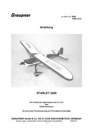
JIVE Regler<br />
Bedienungsanleitung<br />
JIVE Speed Controls<br />
Operation <strong>Manual</strong><br />
1
Inhaltsverzeichnis<br />
1 EINLEITUNG....................................................................................................................................................................4<br />
2 TECHNISCHE DATEN.....................................................................................................................................................4<br />
3 EIGENSCHAFTEN DER JIVE REGLER .........................................................................................................................4<br />
3.1 HIGHLIGHTS: ...................................................................................................................................................................4<br />
3.2 BEC ...............................................................................................................................................................................5<br />
3.3 RINGKERN.......................................................................................................................................................................5<br />
3.4 TIEFENTLADUNGSSCHUTZ ................................................................................................................................................5<br />
3.5 ANSCHLUSS DER KABEL ..................................................................................................................................................5<br />
3.5.1 BEC-KABEL: ................................................................................................................................................................6<br />
3.5.2 MOTOR-KABEL .............................................................................................................................................................6<br />
3.5.3 AKKU KABEL.................................................................................................................................................................6<br />
4 ANPASSUNG DES REGLERS AN DIE FERNSTEUERUNG.........................................................................................7<br />
4.1 DER AUTO-PROGRAMMIER-MODUS APM (MODUS 1) .......................................................................................................8<br />
4.2 DER SEGELFLUG-MODUS (MODUS 2) ...............................................................................................................................9<br />
4.3 DER MOTORFLUG- / BOOT-MODUS (MODUS 3)...............................................................................................................10<br />
4.4 DER HELI-MODUS (MODUS 4) ........................................................................................................................................11<br />
4.5 DER WETTBEWERBS-MODUS (F5B / F5D) (MODUS 5)....................................................................................................12<br />
4.6 MODUS 6.......................................................................................................................................................................13<br />
4.7 DREHRICHTUNGSUMKEHR (MODUS7)..............................................................................................................................14<br />
4.8 MODUS 8 MOTORFLUGMODUS MIT EINSTELLBARER “F3A-BREMSE” ...............................................................................14<br />
4.9 LIPO-MODUS (MODUS 9)................................................................................................................................................15<br />
5 SICHERHEITSHINWEISE..............................................................................................................................................16<br />
6 FEHLERSUCHE.............................................................................................................................................................16<br />
6.1 FEHLER BEIM ANSTECKEN DES AKKUS ...........................................................................................................................16<br />
6.2 FEHLER WÄHREND DER PROGRAMMIERUNG....................................................................................................................16<br />
6.3 FEHLER IM BETRIEB.......................................................................................................................................................17<br />
6.3.1 UNERWARTETE MOTORABSCHALTUNG – WENN SIE NACH DER ABSCHALTUNG KEIN GAS MEHR GEBEN, ZEIGT DIE LED<br />
NACH DER LANDUNG DEN ABSCHALTGRUND AN.........................................................................................................................17<br />
6.3.2 MOTOR LÄSST SICH NICHT EINSCHALTEN:.....................................................................................................................17<br />
7 ALLGEMEINES..............................................................................................................................................................18<br />
7.1 KÜHLUNG / BEFESTIGUNG..............................................................................................................................................18<br />
7.2 TEILLASTFESTIGKEIT .....................................................................................................................................................18<br />
7.3 AKTIVER FREILAUF ........................................................................................................................................................18<br />
7.4 SENSORLOSE KOMMUTIERUNG: .....................................................................................................................................18<br />
7.5 VARIABLE TAKTFREQUENZ.............................................................................................................................................18<br />
7.6 BERATUNG / TECHNISCHE HILFE / HOTLINE ....................................................................................................................18<br />
8 GEWÄHRLEISTUNG .....................................................................................................................................................19<br />
2
1 INTRODUCTION ............................................................................................................................................................21<br />
2 TECHNICAL DATA OF THE JIVE SPEED CONTROLS ..............................................................................................21<br />
3 FEATURES OF THE JIVE SPEED CONTROLS...........................................................................................................21<br />
3.1 BEC .............................................................................................................................................................................22<br />
3.2 TOROIDAL CORE ............................................................................................................................................................22<br />
3.3 LOW VOLTAGE CUT-OFF .................................................................................................................................................22<br />
3.4 CONNECTION OF THE CABLES.........................................................................................................................................22<br />
3.4.1 MOTOR CABLES ..........................................................................................................................................................22<br />
3.4.2 BATTERY CONNCTOR ..................................................................................................................................................22<br />
3.4.3 CONNECTION TO THE RECEIVER...................................................................................................................................23<br />
4 SETTING UP THE SPEED CONTROL TO YOUR EQUIPMENT..................................................................................23<br />
4.1 AUTO-PROGRAMMING-MODE APM - RESET (MODE 1)....................................................................................................24<br />
4.2 GLIDER-MODE (MODE 2) ...............................................................................................................................................25<br />
4.3 MOTOR-PLANE-/ BOAT-MODE (MODE 3) ........................................................................................................................26<br />
4.4 HELI-MODE (MODE 4)....................................................................................................................................................27<br />
4.5 COMPETITION-MODE / FAI MODE (MODE 5) ...................................................................................................................28<br />
4.6 CAR-MODE RACE: ONE DIRECTION, PROPORTIONAL BRAKE (MODE 6).............................................................................29<br />
4.7 REVERSE MOTOR ROTATION (MODE 7) ..........................................................................................................................30<br />
4.8 F3A MOTORPLANE MODE (MODE 8) ..............................................................................................................................30<br />
4.9 LIPO MODE (MODE 9) ....................................................................................................................................................31<br />
5 NOTES ON SAFETY......................................................................................................................................................32<br />
6 TROUBLE SHOOTING ..................................................................................................................................................32<br />
6.1 ERROR WHILE CONNECTION THE BATTERY ......................................................................................................................32<br />
6.2 ERRORS WHILE PROGRAMMING ......................................................................................................................................32<br />
6.3 ERRORS IN USE .............................................................................................................................................................33<br />
6.3.1 UNEXPECTED MOTOR CUT OFF: THE LED SHOWS THE REASON, IF NOT TURNED ON THE THROTTLE AGAIN AFTER CUT OFF<br />
33<br />
6.3.2 MOTOR CAN NOT BE STARTED:.....................................................................................................................................33<br />
7 GENERAL INFORMATION............................................................................................................................................34<br />
7.1 COOLING / FIXING..........................................................................................................................................................34<br />
7.2 PART LOAD CAPABILITY ................................................................................................................................................34<br />
7.3 THE ACTIVE FREE WHEELING CI<strong>RC</strong>UIT..............................................................................................................................34<br />
7.4 SENSORLESS COMMUTATION .........................................................................................................................................34<br />
7.5 VARIABLE PWM SWITCHING FREQUENCY .......................................................................................................................34<br />
7.6 TECHNICAL SUPPORT / HOTLINE/KONTRONIK SERVICE ...............................................................................................34<br />
8 WARRANTY...................................................................................................................................................................35<br />
3
1 Einleitung<br />
Allgemeines<br />
Mit dem JIVE Regler haben Sie ein hochwertiges Elektronikprodukt aus deutscher Entwicklung und Fertigung erworben.<br />
Bitte lesen Sie diese Bedienungsanleitung gründlich durch, um sich mit dem Regler vertraut zu machen und<br />
Fehlbedienungen zu vermeiden.<br />
Die JIVE Regler sind voll teillastfeste sensorlose Regler für bürstenlose Motoren. Sie regeln sehr feinfühlig und verfügen<br />
über einen weichen, ruckfreien und dennoch sehr schnellen Anlauf. Die vordefinierten Betriebs-Modi ermöglichen eine<br />
schnelle Anpassung des JIVE an verschiedene Anwendungen im Flugzeug, Hubschrauber oder Boot. Ein Highlight der<br />
JIVE Regler ist die dynamische, automatische Einstellung der Taktfrequenz und des Kommutierungswinkels. Damit ist<br />
gewährleistet, dass der angeschlossene Motor im aktuellen Lastfall mit dem bestmöglichen Wirkungsgrad betrieben wird.<br />
Speziell im Teillastbetrieb ermöglicht dies längere Flugzeiten bzw. mehr Motorleistung. Dadurch bleibt auch der Motor<br />
kühler. Dies stellt einen großen Vorteil gegenüber der sonst üblichen festen Timingeinstellung dar. Eine weitere Neuheit<br />
ist die Dauerbelastbarkeit. Die spezifizierten Werte können bei entsprechender Kühlung noch deutlich gesteigert<br />
werden.<br />
2 Technische Daten<br />
Typ Eingangsspannung Dauerstrom 1 BEC Spannung<br />
(standard / min -<br />
max)<br />
BEC Strom<br />
(Dauer/max)<br />
JIVE 80+ LV 6V-25V 80A 5,6V / 5V–6V 5A / 15A<br />
JIVE 100+ LV 6V-25V 100A 5,6V / 5V–6V 5A / 15A<br />
JIVE 60+ HV 16-50V 60A 5,6V / 5V–6V 5A / 15A<br />
JIVE 80+ HV 16-50V 80A 5,6V / 5V–6V 5A / 15A<br />
3 Eigenschaften der JIVE Regler<br />
Die JIVE Regler verfügen über eine Modusprogrammierung. Jeder Modus stellt die für den jeweiligen Betriebszustand<br />
benötigten Parameter selbst ein. Eine aufwendige Programmierung der einzelnen Parameter wie z.B. dynamisches-,<br />
drehmoment- oder drehzahloptimiertes Timing, Unterspannungsabschaltung, EMK-Bremse etc. entfällt. Sollen diese<br />
Eigenschaften einzeln verändert werden, so ist dies über ProgCARD (Best.-Nr.: 9305) möglich. Zusätzlich sind über die<br />
ProgCARD II (Best.-Nr.: 9306) weitere Parameter einstellbar (siehe Kapitel 4).<br />
3.1 Highlights:<br />
• Sensorloser Betrieb, es werden keine Sensorsignale vom Motor benötigt<br />
• Modusprogrammierung<br />
o Auto-Programmier-Modus (APM) (Standard - keine Programmierung nötig)<br />
o Segelflug- oder Motorflug- / Boot-Modus<br />
o Heli-Modus, echte Drehzahlregelung möglich<br />
o Wettbewerbsmodus<br />
o Car-Modus : Race: Vorwärts, Prop. Bremse<br />
o Drehrichtungsumkehr<br />
o Lipo-Modus<br />
• EMK-Bremse abschaltbar, Bremsgeschwindigkeit einstellbar<br />
• F3A Bremse, einstellbar in 10% Schritten per Sender bzw. 2,5% Schritten per ProgCARD II<br />
• Automatische Unterspannungsabschaltung, abschaltbar und in der Spannung veränderbar. Abregelung statt<br />
Abschaltung ist möglich.<br />
• Unbegrenzt teillastfest (aktiver Freilauf)<br />
• Selbsttest und Abschaltanalyse (Abschaltgrund wird angezeigt)<br />
• Einstellkontrolle per LED oder akustischem Signal<br />
• Sehr feinfühliges Regelverhalten, kein Ruckeln beim Anlaufen<br />
• Automatische Erfassung der Motorparameter dadurch<br />
1 Bezogen auf 2,4Ah Akkukapazität und 1m/s Kühlluft mit 22°C, kann durch verbesserte Kühlung erheblich gesteigert<br />
werden<br />
4
Allgemeines<br />
o Automatisch angepasste Taktfrequenz (8-32kHz)<br />
o Dynamisches Timing<br />
• Anlauf-, Blockier-, Übertemperaturschutz, Strombegrenzung<br />
• 100% SMD-Technik, sehr klein und leicht, hochflexible, „lötkolbenfeste“ Kabel<br />
• Digitale Mikroprozessorsteuerung, kein Temperaturdrift, „Update-fähig"<br />
• 24 Monate Gewährleistung, CE geprüft, schneller Reparaturservice, kostenlose Hotline<br />
• Entwickelt und produziert in Rottenburg, Deutschland<br />
3.2 BEC<br />
Alle JIVE Regler verfügen über ein leistungsstarkes getaktetes BEC. Im Gegensatz zu herkömmlichen BEC-Systemen ist<br />
die Belastbarkeit dieses BECs weitgehend unabhängig von der Eingangsspannung. Damit ist die Verwendung des BECs<br />
auch bei höheren Spannungen möglich. Zudem zeichnet sich das BEC durch eine bislang ungekannte Störfestigkeit aus.<br />
Bei den JIVE Reglern ist es möglich die BEC Spannung in 0,2V Schritten von 5V bis 6V einzustellen. Aus<br />
Sicherheitsgründen muss parallel zum BEC ein 4-Zelliger NiMH Akku am Empfänger eingesteckt werden. Bei einer<br />
eingestellten BEC-Spannung von mehr als 5,6V sollte eine redundante Empfängerstromversorgung mit<br />
Wechselschaltung verwendet werden.<br />
Ein Betrieb ohne BEC ist ebenfalls möglich. Das rote Empfängerkabel wird dazu jeweils aus dem Stecker gezogen oder<br />
durchtrennt.<br />
Haben Sie Fragen oder sind Sie sich unsicher? Gerne können Sie unsere aus Deutschland kostenlose Hotline in<br />
Anspruch nehmen (Tel.: 0800 / BRUSHLESS)<br />
3.3 Ringkern<br />
Der Ringkern in den Empfängeranschlusskabeln dient der Störunterdrückung und ist für die Betriebssicherheit des<br />
Reglers notwendig und darf nicht entfernt werden. Er kann bei Bedarf aber innerhalb des Kabels verschoben werden.<br />
3.4 Tiefentladungsschutz<br />
Die JIVE Regler sind je nach Modus mit einem automatischen Tiefentladungsschutz ausgestattet. Dieser schaltet den<br />
Motor ab, wenn die Akkuentladespannung erreicht ist (NiMH: ca.0.8V/Zelle). Der Motor kann jedoch per Fernsteuerung<br />
wieder eingeschaltet werden, indem der Gasknüppel zuerst in die Motor-Aus-Stellung und anschließend wieder in die<br />
gewünschte Gas-Stellung gebracht wird. Bitte beachten Sie die veränderte Abschaltspannung (2,7V/Zelle) im Lipo–<br />
Modus! Die Abschaltspannungen können mit der ProgCARD verändert werden.<br />
3.5 Anschluss der Kabel<br />
Programmierstecker<br />
Empfänger<br />
(beliebiger<br />
Steckplatz)<br />
Empfänger<br />
(Kanal mit<br />
Gasfunktion)<br />
5
Allgemeines<br />
3.5.1 BEC-Kabel:<br />
Mit 5A Dauerstrom und 15A Maximalstrom ermöglicht der JIVE die Verwendung des BEC auch zur Versorgung<br />
leistungsstarker Digitalservos. Um den Übergangswiderstand zu minimieren verfügen alle JIVE Regler über zwei BEC<br />
Anschlussbuchsen. Um das BEC voll belasten zu können müssen immer beide Buchsen über die mitgelieferten Kabel<br />
mit integriertem Ringkern verwendet werden. Die mit „Master“ gekennzeichnete Buchse muss dabei an dem<br />
Empfängerkanal angeschlossen werden der die Gasfunktion übernimmt. Die „Slave“-Buchse kann mit jedem beliebigen<br />
freien Empfängerkanal (auch einem Batterieanschluss) verbunden werden.<br />
WARNUNG: Achten Sie unbedingt auf die korrekte Polung der Steckverbindungen am Empfänger! Viele Empfänger mit<br />
„UNI“-Stecksystem haben keine verpolsicheren Buchsen. Eine falsche Polung der BEC Kabel am Empfänger kann zu<br />
Schäden am Empfänger und den angeschlossenen Servos führen!<br />
3.5.2 Motor-Kabel<br />
Die Reihenfolge ist beliebig. Das Tauschen von 2 Motorkabeln ändert die Motordrehrichtung (siehe auch Modusprogrammierung<br />
Modus 7).<br />
Sollte der Motor über Sensorleitungen verfügen, so werden diese nicht benötigt und bleiben unbenutzt.<br />
3.5.3 Akku Kabel<br />
An den Akkukabeln sollten verpolungssichere Stecker verwendet werden, da eine Verpolung irreparable Schäden<br />
hervorruft. Eine Verpolung wird im Fehlerspeicher hinterlegt und kann vom Service ausgelesen werden.<br />
6
4 Anpassung des Reglers an die Fernsteuerung<br />
Programmierung<br />
Der JIVE Regler kann sowohl mit dem Fernsteuersender als auch mit den Programmierkarten eingestellt werden. Für<br />
die Programmierung per Sender sind Einstellungen für verschiedene Anwendungen vorgegeben<br />
(Modusprogrammierung). Zusätzlich können mit der ProgCARD und der ProgCARD II die Einstellungen der Modi<br />
verändert werden:<br />
ProgCARD:<br />
• Knüppelwege fest/APM, einlernen des<br />
Knüppelwegs<br />
• Unterspannungsabschaltung<br />
o NiMH: 0,7V/0,8V/0,9V/1,0V pro Zelle<br />
o Lipo: 2,5V/2,7V/2,8V/3,0V pro Zelle<br />
• Bremse Ein/Aus<br />
• Drehzahlregelung Ein/Aus<br />
• Hochlaufzeit bei Drehzahlregelung 6/8/10/12<br />
Sekunden<br />
• Motortiming: Auto/-5°/+5°/+10°/+15°<br />
• Ansprechverhalten: weich/schnell<br />
ProgCARD II<br />
• „F3A-Bremse“ 10% bis 100% in 2,5%<br />
Schritten<br />
• BEC-Spannung (5,0V bis 6,0V in 0,2V<br />
Schritten)<br />
• Drehrichtungsumkehr<br />
• Feineinstellung der Regelparameter für die<br />
Drehzahlregelung<br />
• Verkürzung der „Hold“-Funktion bei<br />
ungültigem Empfangssignal<br />
Der Regler befindet sich im Neuzustand im APM (Auto-Programmier-Modus), d.h. er gleicht sich selbst auf die<br />
Knüppelwege der Fernsteuerung ab:<br />
a) Sender einschalten - Gasknüppel auf Anschlag EMK-Bremse stellen.<br />
b) Empfänger einschalten.<br />
c) Antriebsakku an JIVE Regler anschließen.<br />
d) Vor dem Start oder beim Start für mind. 1sec. Vollgas geben.<br />
e) Fertig.<br />
Sollte der Motor nicht anlaufen: Antriebsakku abziehen und im Sender die Funktion „Drehrichtungsumkehr“ einbzw.<br />
ausschalten. Weiter ab a).<br />
In allen andern Modi der Modusprogrammierung werden die Knüppelwege fest programmiert und müssen nicht<br />
bei jedem Start neu eingelernt werden.<br />
7
4.1 Der Auto-Programmier-Modus APM (Modus 1)<br />
Programmierung<br />
Im APM „lernt“ der Regler nach jedem Anstecken des Akkus die Knüppelwege selbständig neu ein. Die<br />
Bremsgeschwindigkeit steht auf Mitte (ca. 0,5 sec.), die Unterspannungsabschaltung ist auf 0,8 V/Zelle (NiMH)<br />
eingestellt.<br />
Das Programmieren des APM löscht alle bisherigen Einstellungen und versetzt den JIVE Regler in den<br />
Auslieferungszustand. (Reset)<br />
Programmierablauf des Auto-Programmier-Modus<br />
Jumper (schwarzer Stecker) auf 2 beliebige der 3 Programmierkontakte aufstecken.<br />
Für ein akustisches Signal, den Motor am Regler anschließen.<br />
Sender und Empfänger einschalten. Gasknüppel in<br />
Bremsstellung bringen (Knüppel hinten).<br />
Antriebsakku anstecken.<br />
2 sec. warten, oder bis<br />
aufsteigende Tonfolge<br />
Jumper abziehen.<br />
absteigende Tonfolge<br />
Gas-Knüppel in Vollgasstellung bringen (Knüppel vorn).<br />
absteigende Tonfolge<br />
Kontrollausgabe<br />
Fertig - Antriebsakku abziehen.<br />
8
Programmierung<br />
4.2 Der Segelflug-Modus (Modus 2)<br />
Alle für den Betrieb eines Seglers benötigten Eigenschaften werden selbständig eingestellt.<br />
• Die Bremsgeschwindigkeit ist auf Mitte (ca. 0,5 sec.) eingestellt, und damit auch für den Einsatz von<br />
Getriebeantrieben geeignet.<br />
• Die Unterspannungsabschaltung von 0,8 V/Zelle (NiMH) schließt eine Tiefenentladung des Akkus aus.<br />
• Der Übertemperaturschutz und die Strombegrenzung des Reglers sind aktiviert, um bei Überlastung den Motor<br />
abzuschalten.<br />
• Die Gaskennlinie ist für den Betrieb mit Luftschrauben optimiert.<br />
• Die Anlaufgeschwindigkeit ist auf große, langsam laufende Luftschrauben optimiert.<br />
• Außer der Brems- und der Vollgas-Position kann eine separate Motor-Aus-Position des Gasknüppels programmiert<br />
werden. In dieser Knüppelstellung ist der Motor ausgeschaltet, die Bremse aber noch nicht aktiv. Beim Klapppropeller<br />
bleibt dieser gezielt offen um das Modell zu bremsen. Dies wird als Thermikbremse genutzt.<br />
• Wird keine separate Motor-Aus-Stellung programmiert, so ist die Motor-Aus-Stellung mit der Bremsstellung identisch.<br />
Programmierablauf des Segelflugmodus-Modus (Modus 2)<br />
Jumper auf 2 beliebige der 3 Programmierkontakte aufstecken.<br />
Für ein akustisches Signal, den Motor am Regler anschließen.<br />
Sender und Empfänger einschalten. Gas-Knüppel in Bremsstellung bringen<br />
(Knüppel hinten).<br />
Antriebsakku anstecken.<br />
2 sec. warten, oder bis<br />
aufsteigende Tonfolge<br />
Jumper abziehen.<br />
absteigende Tonfolge<br />
...<br />
Gas-Knüppel in Vollgasstellung bringen (Knüppel vorn).<br />
absteigende Tonfolge<br />
Jetzt kann der Gas-Knüppel in eine separate Motor-<br />
Aus-Stellung gebracht werden (optional).<br />
absteigende Tonfolge<br />
Kontrollausgabe<br />
Fertig - Antriebsakku abziehen.<br />
9
4.3 Der Motorflug- / Boot-Modus (Modus 3)<br />
Programmierung<br />
Alle für den Betrieb eines Motormodells oder Rennbootes benötigten Eigenschaften werden selbstständig eingestellt.<br />
• Im Motorflug- / Boot-Modus ist die EMK-Bremse des Reglers ausgeschaltet.<br />
• Die Unterspannungsabschaltung von 0,8 V/Zelle ist deaktiviert, da im Motormodell oder Boot ein Absinken der<br />
Versorgungsspannung deutlich zu spüren ist, und so die Flugfähigkeit bzw. die Manövrierfähigkeit des Modells bis zu<br />
Schluss erhalten bleibt.<br />
• Der Übertemperaturschutz und die Strombegrenzung des Reglers sind aktiviert, um bei Überlastung den Motor<br />
abzuschalten.<br />
• Die Gaskennlinie ist für den Betrieb mit Luftschrauben und Schiffspropeller optimiert.<br />
Programmierablauf des Motorflug- / Boot-Modus (Modus 3)<br />
Jumper auf 2 beliebige der 3 Programmierkontakte aufstecken.<br />
Für ein akustisches Signal, den Motor am Regler anschließen.<br />
Sender und Empfänger einschalten.<br />
Gas-Knüppel in Motor-Aus-Stellung bringen (Knüppel hinten).<br />
Antriebsakku anstecken.<br />
2 sec. warten, oder bis<br />
aufsteigende Tonfolge<br />
Jumper abziehen.<br />
absteigende Tonfolge<br />
... ...<br />
Gas-Knüppel in Vollgasstellung bringen (Knüppel vorn).<br />
absteigende Tonfolge<br />
Kontrollausgabe<br />
Fertig - Antriebsakku abziehen.<br />
10
4.4 Der Heli-Modus (Modus 4)<br />
Programmierung<br />
Der Heli-Modus des JIVE Reglers aktiviert die Drehzahlregelung. Das bedeutet, dass die Motordrehzahl konstant<br />
gehalten wird. Lastschwankungen und das Absinken der Akkuspannung werden kompensiert, solange die Leistung des<br />
Akkus und des Motors dafür ausreichen. Es wird kein separater Mixer der Fernsteuerung benötigt, um die Rotordrehzahl<br />
zu stabilisieren. Diese Drehzahlregelung funktioniert nur im eingebauten Zustand. Wird der Motor ohne die<br />
Schwungmasse des Helikopters betrieben, kann ein ruckender Betrieb entstehen.<br />
Das Fernsteuerkabel des Reglers wird in einen freien Empfängeranschluss gesteckt, der vom Sender aus mittels<br />
Schieberegler (ohne Mischer) bedient wird. Dieser Schieber wird dann auch zum Programmieren des Heli-Modus<br />
verwendet.<br />
Die Drehzahlregelung des JIVE lernt sich beim ersten Start des Motors nach dem Anstecken des Akkus selbständig auf<br />
die Anwendung ein. Am besten immer auf 0° Pitch stellen, damit die Drehzahl bei jedem Flug annähernd gleich ist.<br />
Zum Starten, den Schieber Richtung Vollgas schieben. Mittels Sanftanlauf erhöht der Regler innerhalb einiger Sekunden<br />
die Motordrehzahl. Wenn die für die Drehzahlregelung nötige Drehzahl erreicht ist, schaltet er auf Regelung um. Je näher<br />
der Schieber der Vollgasstellung kommt, desto höher ist die eingeregelte Drehzahl.<br />
Erreicht der Schieber die Motor-Aus Stellung, so wird der Motor ausgeschaltet. Dies sollte während des Fluges<br />
vermieden werden, da ansonsten zum Wiederanfahren durch den Sanftanlauf einige „lange“ Sekunden benötigt werden.<br />
Um festzustellen, ob Motor, Getriebeübersetzung, Akku und Hubschrauber richtig auf einander abgestimmt sind, gibt es<br />
eine Kontrollmöglichkeit: Nachdem der JIVE Regler abgeglichen ist, sollte die niedrigste einstellbare Drehzahl nicht zum<br />
Abheben des Hubschraubers ausreichen. Ist dies dennoch der Fall, so wird der JIVE Regler jenseits seiner<br />
Maximalwerte betrieben und ist vermutlich überlastet. Dann muss eine höhere Getriebeübersetzung oder ein Motor mit<br />
geringerer Drehzahl und mehr Drehmoment eingesetzt werden!<br />
Im Heli-Modus sind folgende Schutzmechanismen aktiviert:<br />
• Wenn mehr als drei Sekunden kein Empfangssignal erkannt wird, schaltet der Regler den Motor ab.<br />
• Bei Übertemperatur regelt er langsam (ca. 30sec.) das Gas auf Null ab.<br />
• Wenn der Lipo-Modus aktiviert ist führt die Erkennung der Unterspannungsabschaltung ebenfalls zur langsamen<br />
Abregelung, ohne Lipo-Modus ist die Unterspannungsabschaltung deaktiviert. Im Lipo Modus sollte nicht bis zur<br />
Unterspannungsabschaltung geflogen werden, da diese aus Sicherheitsgründen später greift als in den anderen<br />
Modi.<br />
Ein erneuter Start ist erst nach Trennen und Wiederanstecken des Akkus möglich.<br />
Programmierablauf des Heli-Modus (Modus 4)<br />
Jumper auf 2 beliebige der 3 Programmierkontakte aufstecken.<br />
Für ein akustisches Signal, den Motor am Regler anschließen.<br />
Sender und Empfänger einschalten. Schieberegler in Motor-Aus-Stellung bringen (Stellung hinten).<br />
Antriebsakku anstecken.<br />
2 sec. warten, oder bis<br />
aufsteigende Tonfolge<br />
Jumper abziehen.<br />
absteigende Tonfolge<br />
... ... ...<br />
Schieberegler in Vollgasstellung bringen (Stellung vorn).<br />
absteigende Tonfolge<br />
Kontrollausgabe<br />
Fertig - Antriebsakku abziehen.<br />
11
4.5 Der Wettbewerbs-Modus (F5B / F5D) (Modus 5)<br />
Programmierung<br />
Alle für den Betrieb eines Wettbewerbsmodells benötigten Eigenschaften werden selbständig eingestellt.<br />
• Die Anlaufgeschwindigkeit ist für schnellen Anlauf mit großen Luftschrauben optimiert.<br />
• Die EMK-Bremsleistung des Reglers steht auf maximaler Ansprechgeschwindigkeit, um ein sofortiges Anklappen der<br />
Luftschraube zu erreichen.<br />
Achtung: Dies führt zu großen Kräften, denen alle Komponenten gewachsen sein müssen.<br />
• Die Unterspannungsabschaltung und die Übertemperaturabschaltung ist deaktiviert, da im Wettbewerb störend.<br />
Achtung: Für ausreichend Kühlung sorgen.<br />
• Die Strombegrenzung ist maximiert.<br />
• Zum Schutz des Reglers ist die Zeit, in der Teillast zugelassen wird, begrenzt. Wird sie überschritten schaltet der<br />
Regler ab.<br />
• Zum Start sind 6sec Teillast erlaubt. Sind die ersten Einschaltzeiten in Summe kürzer als 2sec (z.B. zum Test) so<br />
zählt das nicht. Alle weiteren Einschaltungen lassen 1sec Teillast zu, danach schaltet der JIVE ab.<br />
Programmierablauf des Wettbewerbs-Modus (Modus 5)<br />
Jumper auf 2 beliebige der 3 Programmierkontakte aufstecken.<br />
Für ein akustisches Signal, den Motor am Regler anschließen.<br />
Sender und Empfänger einschalten. Motorschalter in<br />
Bremsstellung bringen (Schalter hinten).<br />
Antriebsakku anstecken.<br />
2 sec. warten, oder bis<br />
aufsteigende Tonfolge<br />
Jumper abziehen.<br />
absteigende Tonfolge<br />
... ... ...<br />
Motorschalter in Vollgasstellung bringen (Schalter vorn).<br />
Kontrollausgabe<br />
absteigende Tonfolge<br />
Fertig - Antriebsakku abziehen.<br />
12
4.6 Modus 6 (Car-Modus)<br />
Programmierung<br />
Alle für den Betrieb eines Modellautos benötigten Eigenschaften werden selbständig eingestellt.<br />
• Die EMK-Bremse des Reglers arbeitet proportional, d.h. bei der Programmierung ist ein ausreichender Knüppelweg<br />
für die Bremse notwendig.<br />
• Die Anlaufparameter sind für das Anfahren im Auto optimiert.<br />
• Die Unterspannungsabschaltung von 0,8 V/Zelle (NiMH) ist deaktiviert, der Lipo Modus ist zusätzlich programmierbar<br />
• Der Übertemperaturschutz und die Strombegrenzung des Reglers sind aktiviert, um bei Überlastungen den Motor<br />
abzuschalten.<br />
• Die Ansprechgeschwindigkeit ist maximiert, um ein direktes Fahrgefühl zu vermitteln.<br />
• Die Gaskennlinie ist auf den Fahrbetrieb abgestimmt.<br />
Programmierablauf des Car-Modus Race (Modus 6)<br />
Jumper auf 2 beliebige der 3 Programmierkontakte aufstecken.<br />
Für ein akustisches Signal, den Motor am Regler anschließen.<br />
Sender und Empfänger einschalten. Gas-Knüppel in<br />
Motor-Aus-Stellung bringen (Knüppel in der Mitte).<br />
Antriebsakku anstecken.<br />
2 sec. warten, oder bis<br />
Jumper abziehen.<br />
aufsteigende Tonfolge<br />
... ... ...<br />
absteigende Tonfolge<br />
Gas-Knüppel in Vollgasstellung bringen (Knüppel vorn).<br />
absteigende Tonfolge<br />
Gas-Knüppel in Bremsstellung bringen (Knüppel hinten).<br />
absteigende Tonfolge<br />
Kontrollausgabe<br />
Fertig - Antriebsakku abziehen.<br />
13
4.7 Drehrichtungsumkehr (Modus7)<br />
Programmierung<br />
Um die Drehrichtung des Motors umzukehren, entweder zwei Motorkabel tauschen oder den Modus 7 programmieren.<br />
Er verändert vorher programmierte Eigenschaften nicht. Dazu bei der Programmierung auf das 7-fach Signal warten,<br />
ansonsten wie bei Modus 3.<br />
Modus 7 lässt sich nur programmieren, wenn zuvor irgendein Modus außer Modus 1 programmiert wurde.<br />
4.8 Modus 8 Motorflugmodus mit einstellbarer “F3A-Bremse”<br />
Dieser Modus entspricht im Wesentlichen Modus 3 (Motorflugmodus), zusätzlich kann in diesem Modus eine fest<br />
einstellbare Motorbremse programmiert werden („F3A-Bremse“). Diese dient dazu Flugmodelle in Abwärtspassagen zu<br />
bremsen. Mit der ProgCARD II kann die Bremsstärke in 2,5% Schritten eingestellt werden.<br />
Programmierablauf<br />
Jumper auf 2 beliebige der 3 Programmierkontakte aufstecken.<br />
Für ein akustisches Signal, den Motor am Regler anschließen.<br />
Sender und Empfänger einschalten. Gas-Knüppel in<br />
Motor-Aus-Stellung bringen (Knüppel in der Mitte).<br />
Antriebsakku anstecken.<br />
2 sec. warten, oder bis<br />
aufsteigende Tonfolge<br />
Jumper abziehen.<br />
absteigende Tonfolge<br />
... ...<br />
Gas-Knüppel in Vollgasstellung bringen (Knüppel vorn halten).<br />
Signaltöne für die Stärke der F3A Bremse, jeder Ton entspricht 10% Bremsstärke<br />
Bei gewünschter Bremsstärke Gas-Knüppel in Motor-Aus Stellung bringen.<br />
absteigende Tonfolge<br />
Kontrollausgabe<br />
Fertig - Antriebsakku abziehen.<br />
14
Programmierung<br />
4.9 Lipo-Modus (Modus 9)<br />
Diesen Modus zusätzlich programmieren um auf die automatische Unterspannungsabschaltung für Lipo-Akkus (Abschaltspannung<br />
2,7V bis 3V/Zelle) je nach Last umzustellen.<br />
Er verändert vorher programmierte Eigenschaften nicht. Dazu bei der Programmierung auf das 9-fach Signal warten,<br />
ansonsten wie bei Modus 3.<br />
Zur Erkennung der veränderten Unterspannungsabschaltung ist die Tonfolge beim Anstecken des Flugakkus geändert.<br />
Die Anzahl der Pieptöne entspricht der Anzahl der erkannten Lipo-Akkus.<br />
ACHTUNG: Das Programmieren dieses Modus aktiviert die Unterspannungsabschaltung auch in den Modi, in<br />
denen ansonsten die Unterspannungsabschaltung deaktiviert ist.<br />
NEU: Bei aktiviertem Lipomodus wird beim anstecken des Akkus die erkannte Zellenzahl akustisch<br />
ausgegeben. Ist die erkannte Zellenzahl geringer als die reale sollte nicht geflogen werden, da sonst die<br />
Abschaltung zu spät greifen würde. In diesem Fall sollte der Akku vor dem Flug nachgeladen werden.<br />
15
5 Sicherheitshinweise<br />
Service und Gewährleistung<br />
• Nicht den Akku vom JIVE Regler abziehen, solange der Motor noch läuft.<br />
• Nicht den Regler selbst mit Kabelbindern o.ä. befestigen. Es könnten Bauteile beschädigt werden.<br />
• Sobald Antriebsakku und Motor an den Regler angeschlossen sind, besteht die Möglichkeit, dass der Motor anläuft<br />
(z.B. durch Fehlbedienung oder durch elektrischen Defekt). Höchste Vorsicht ist ab diesem Zeitpunkt geboten.<br />
• Ein Elektromotor (speziell mit Luftschraube) kann erhebliche Verletzungen verursachen. Ebenso können durch<br />
umherfliegende Teile erhebliche Verletzungen hervorgerufen werden.<br />
• Der Betrieb dieses Reglers ist nur in Situationen zulässig, in denen Sach- und Personenschäden ausgeschlossen<br />
sind.<br />
• Einen beschädigten Regler (z.B. durch mechanische oder elektrische Einwirkung, durch Feuchtigkeit, usw.) keinesfalls<br />
weiter verwenden. Anderenfalls kann es zu einem späteren Zeitpunkt zu einem plötzlichen Versagen des Reglers<br />
kommen.<br />
• Der Regler ist nur zum Einsatz in Umgebungen vorgesehen, in denen keine Entladung von statischer Elektrizität<br />
auftritt.<br />
• Der Regler darf nur aus NiCd-, NiMH-, Lipo- oder Blei-Akkumulatoren gespeist werden. Ein Betrieb an Netzgeräten ist<br />
nicht zulässig. Es darf in keinem Falle eine elektrische Verbindung zwischen dem Regler und dem 230V Wechselstromnetz<br />
hergestellt werden. Bei Akkumulatoren mit hoher Kapazität muss gewährleistet sein, dass der Regler<br />
ausreichend gekühlt wird.<br />
• Eine Verlängerung der Akku- oder Motorkabel sind nicht zulässig, da ansonsten die Einhaltung gesetzlicher<br />
Vorschriften nicht gewährleistet ist. Zu lange Akkukabel können zur Beschädigung des Reglers führen.<br />
• Bei Strommessungen ist unbedingt ein Zangenampermeter zu verwenden, da ein eingeschleiftes Messgerät / -shunt<br />
den Regler beschädigen kann.<br />
• Vor dem Erstflug müssen Tests am Boden durchgeführt werden, um sicherzustellen, dass die BEC-Belastbarkeit für<br />
die jeweilige Anwendung ausreicht.<br />
• Grundsätzlich ist immer für genug Kühlung zu sorgen, um ein Überhitzen des Reglers zu verhindern.<br />
6 Fehlersuche<br />
6.1 Fehler beim Anstecken des Akkus<br />
Der JIVE Regler verfügt über einen zweiten Microprozessor, bereits beim Anstecken des Akkus wird ein umfangreicher<br />
Selbstest durchgeführt, wenn der Regler nach dem Selbsttest nicht funktioniert und einen Fehlercode ausgibt wenden Sie<br />
sich bitte an die Hotline oder schicken Sie eine Email an info@kontronik.com.<br />
6.2 Fehler während der Programmierung<br />
• Es kommt kein Signal:<br />
o Der Sender ist nicht eingeschaltet.<br />
o Der Regler ist nicht oder falsch im Empfänger eingesteckt<br />
o Es ist kein Empfängerakku angeschlossen.<br />
• Signal - dann Dauerlicht oder kein weiteres Signal:<br />
o Die Knüppelstellung „hinten“ (Brems- bzw. Motor-Aus-Stellung) ist zu dicht an der Knüppelstellung „vorne“<br />
(Vollgasstellung).<br />
o Der Abstand zwischen der Knüppelstellung „hinten“ (Brems- bzw. Motor-Aus-Stellung ) und Knüppelstellung<br />
„vorne“ (Vollgasstellung) ist zu groß. Dieser Fehler kann nur bei Computersendern auftreten.<br />
Abhilfe: Den Servoweg für den Gas-Knüppel auf +/-100% (ggf. auch weniger) programmieren.<br />
o Starke Verschiebung der Knüppelstellungen in Richtung lange Impulse (eine der Knüppelstellungen muss eine<br />
Impulslänge kürzer als 2ms besitzen). Dieser Fehler kann nur bei Computersendern auftreten.<br />
Abhilfe: Am Fernsteuersender keine Verschiebung (Offset) der Servowege programmieren.<br />
16
6.3 Fehler im Betrieb<br />
Service und Gewährleistung<br />
6.3.1 Unerwartete Motorabschaltung – Wenn Sie nach der Abschaltung kein Gas mehr geben, zeigt die LED<br />
nach der Landung den Abschaltgrund an.<br />
Blinkcode: Bedeutung Abhilfe<br />
Einfach Unterspannung<br />
Zweifach Überstromabregelung (Softwareerkennung) Kleinerer Propeller oder Antriebsakku mit<br />
weniger Zellen verwenden<br />
Dreifach Übertemperatur Für bessere Kühlung sorgen<br />
Vierfach Mehr als 4s keine Empfängerimpulse Reichweitentest durchführen und<br />
Empfangsanlage optimieren<br />
Fünffach Zu lange Teillast in Modus 5 Teillast vermeiden, ggf. Programmierung<br />
kontrollieren (Temperaturdrift des Senders)<br />
Sechsfach Hardware Reset im Betrieb wegen Unterspannung der BEC Überlast?<br />
internen Stromversorgung<br />
Siebenfach Unerwarteter Reset im Betrieb<br />
Achtfach Hard ware Überstromerkennung, sofortiges Abschalten,<br />
kein Abregeln möglich, kein Wiedereinschalten möglich<br />
Extreme Überlast, möglicherweise durch<br />
mechanisch blockierten Motor, ggf. Mechanik<br />
kontrollieren<br />
Kann der Abschaltgrund nicht zuverlässig verhindert werden, sollte in jedem Fall der KONTRONIK Service<br />
kontaktiert werden, um eine Zerstörung des Reglers zu vermeiden.<br />
Tel.: 0800 / Brushless (aus Deutschland kostenlos)<br />
6.3.2 Motor lässt sich nicht einschalten:<br />
Der Regler gibt nach Anschluss des Antriebsakkus den Motor erst frei nach Erkennung der Knüppelstellung „hinten“<br />
(Brems- bzw. Motor-Aus-Stellung ) oder „Neutral“ (Motor-Aus-Stellung). Erkennt der Regler keine dieser Stellungen,<br />
erfolgt kein aufsteigender Dreifachton<br />
und der Motor bleibt ausgeschaltet.<br />
Abhilfe:<br />
• Position der Trimmung des Gas-Knüppel beachten und auf Motor-Aus bzw. Bremse stellen.<br />
• Den Regler auf die aktuellen Servowege programmieren.<br />
• Manche Fernsteueranlagen weisen eine gewisse Temperaturdrift der Servowege auf. In diesem Fall empfiehlt es<br />
sich, bei der Programmierung etwas Abstand von den Anschlagstellungen des Gasknüppels einzuhalten, um im<br />
Betrieb etwas Reserveweg zur Verfügung zu haben.<br />
.<br />
17
Service und Gewährleistung<br />
7 Allgemeines<br />
Mit diesem JIVE Regler haben Sie ein hochwertiges Produkt erworben. Hochwertige Steckkontakte (z.B. KONTRONIK<br />
Stecker Best.Nr.: 9010) sowie niederohmig verlötete Akkus sollten daher obligatorisch sein. Sollten Sie noch Fragen bzgl.<br />
des Einsatzes dieses Reglers haben (z.B. tats. auftretende Motorströme) bitte den KONTRONIK Service kontaktieren.<br />
7.1 Kühlung / Befestigung<br />
Ausreichende Kühlung verbessert den Wirkungsgrad und die Lebensdauer des Reglers. Muss der Regler im Modell fixiert<br />
werden, sollte dies nach Möglichkeit über die Kabel geschehen. Ansonsten die Etikettenseite des JIVE zur Befestigung<br />
benutzen. Keinesfalls darf die Kühlplatte z.B. mit Klettband beklebt werden.<br />
7.2 Teillastfestigkeit<br />
Der JIVE Regler ist durch seinen aktiven Freilauf voll teillastfest. Dies gilt, solange bei Vollgas und Volllast der Akkustrom<br />
die zulässige Dauerstromgrenze nicht überschreitet (z.B. beim JIVE80+ entspricht dies 80A).<br />
7.3 Aktiver Freilauf<br />
Um den Wirkungsgrad im Teillastbereich zu optimieren, verfügen JIVE Regler über den aktiven Freilauf. Er verbessert<br />
den Wirkungsgrad im Teillastbetrieb und verringert so die Erwärmung des Reglers. Der aktive Freilauf wird bei zu wenig<br />
Last abgeschaltet. Dies kann zu einem kleinen Drehzahlsprung führen.<br />
7.4 Sensorlose Kommutierung:<br />
Der JIVE Regler arbeitet ohne Sensoren im Motor. Er arbeitet mit einem 3D Kennfeld. Eine Veränderung der<br />
Kommutierung erfolgt automatisch und ist nun dynamisch statt bisher statisch. Der JIVE Regler kann jedoch ohne dass<br />
sich der Motor dreht dessen Rotorposition nicht erkennen. Aus diesem Grund ist es möglich, dass beim Anlaufen der<br />
Motor minimal schwingt.<br />
7.5 Variable Taktfrequenz<br />
Die JIVE Regler verändern die verwendete Taktfrequenz zwischen 8 und 32 kHz. Die Höhe der Taktfrequenz ist<br />
abhängig vom Motor und der momentanen Belastung und wird optimal auf diese Parameter abgestimmt. Der Motor<br />
arbeitet somit immer im Punkt des optimalen Wirkungsgrades.<br />
7.6 Beratung / Technische Hilfe / Hotline<br />
Normalerweise Montag bis Donnerstag von 8:00 bis 12.00 und 13.00 bis 16.00Uhr, Freitags von 8:00 bis 12.00Uhr.<br />
Tel.: +49 / (0)7457 / 9435-0<br />
FAX: +49 / (0)7457 / 9435-90<br />
Email: info@kontronik.com<br />
Homepage: www.kontronik.com<br />
Hotline : 0800 / BRUSHLESS (0800 / 278745377) - (aus Deutschland kostenlos)<br />
18
Service und Gewährleistung<br />
8 Gewährleistung<br />
Wir gewähren 24 Monate Gewährleistung auf dieses Produkt. Alle weitergehenden Ansprüche sind ausgeschlossen.<br />
Dies gilt insbesondere für Schadensersatzansprüche die durch Ausfall oder Fehlfunktion ausgelöst wurden. Für<br />
Personenschäden, Sachschäden und deren Folgen, die aus unserer Lieferung oder Arbeit entstehen, können wir,<br />
außer bei Vorsatz oder grober Fahrlässigkeit unsererseits, keine Haftung übernehmen, da uns eine Kontrolle der<br />
Handhabung und Anwendung nicht möglich ist.<br />
Zur Anerkennung der Gewährleistung muss ein maschinenerstellter Originalkaufbeleg, auf dem das Produkt, das<br />
Kaufdatum und die Bezugsquelle erkennbar sind, beigelegt sein. Eine genaue Fehlerbeschreibung ist ebenso<br />
notwendig. (Verwendeter Motor, Luftschraube, Anzahl und Typ der Akkus. Wann trat der Fehler auf? Wurde vor dem<br />
Ausfall etwas außergewöhnliches bemerkt?)<br />
Bitte vergessen Sie nicht die korrekte Rücksendeadresse anzugeben.<br />
EG-Konformitätserklärung<br />
Für die JIVE Regler wird hiermit bestätigt, dass Sie den EMV-Richtlinien<br />
89/336/EWG, 91/263/EWG und 92/31/EWG entsprechen.<br />
Folgende Fachgrundnormen wurden herangezogen: EN 61000-6-1<br />
Rottenburg, den 14.02.2008, KONTRONIK GmbH<br />
19
JIVE Speed Controls<br />
Operation <strong>Manual</strong><br />
20
Introduction<br />
1 Introduction<br />
The JIVE speed controls are high end products made in Germany. Please read this manual to avoid failures when using<br />
the JIVE.<br />
The JIVE speed controls are designed for brushless motors. They work without sensors in the motor and have full part<br />
load capability. The JIVE Speed controls provide a soft and yet very fast start up. The built-in RPM control (Governormode)<br />
is optimized for powered helicopters and the mode programming helps to program all the various parameters in a<br />
very simple way essentially.<br />
A highlight of the JIVE speed control is the dynamic automatic adjusting of its PWM switching frequency and motor<br />
timing. This ensures that, depending on the actual used powersetting, the connected motor always runs in its best point<br />
of efficiency. Especially in partial load this allows more flight time or more power and the motor stays cooler. This is a<br />
tremendous advantage in comparison to the normally used fixed timing.<br />
2 Technical data of the JIVE speed controls<br />
Type Input Voltage Constant Current BEC Voltage<br />
(standard / min /<br />
max)<br />
BEC Current<br />
(cont./max)<br />
JIVE 80+ LV 6V-25V 80A 5,6V / 5V–6V 5A / 15A<br />
JIVE 100+ LV 6V-25V 100A 5,6V / 5V–6V 5A / 15A<br />
JIVE 60+ HV 16-50V 60A 5,6V / 5V–6V 5A / 15A<br />
JIVE 80+ HV 16-50V 80A 5,6V / 5V–6V 5A / 15A<br />
3 Features of the JIVE speed controls<br />
The JIVE speed controls utilize an operation mode programming for the user’s convenience. It is not necessary to<br />
program the individual properties itself (as dynamic-, torque- or RPM-related change of timing, the EMF-brake or the<br />
undervoltage cut off etc.). If the properties shall be modified individually, this is possible via the ProgCARD (order no.<br />
9305) and the new ProgCARD II (order no. 9306).<br />
The Jive speed controls have the following features:<br />
• Sensorless, no sensor signals from the motor are required<br />
• Mode programming<br />
o Auto-Programming-Mode (APM)<br />
o Glider-Mode or Motor-Plane- / Boat-Mode<br />
o Heli-Mode with active RPM control<br />
o Competition-Mode (F5B / F5B 10 cells / F5D)<br />
o Car-Mode Race (one direction, prop.brake)<br />
o Reverse Motor Rotation<br />
o Lipo Mode<br />
• EMF-brake with variable brake rate, can be disabled<br />
• Automatic under voltage disconnection, adjustable, which can be disabled. Reducing power, instead of cut off, is<br />
possible.<br />
• Unlimited part load capability<br />
• F3A Brake (adjustable in 10% steps by transmitter or in 2,5% steps by using ProgCARD II)<br />
• Analysis of shut down reason (error-code shown by LED)<br />
• Adjusting monitored by LED or audible signal<br />
• Very sensitive control characteristic, smooth start up<br />
• Sensing and computing of the actual motor data<br />
− self adjusting beat frequency (8-32kHz)<br />
− dynamic timing<br />
• Start up protection at power up, blocked motor protection, overtemperature protection, over current limitation<br />
• 100% surface mount technology (very small and light), highly flexible, heat-resistant cables<br />
• Dual digital microprocessor control, therefore no thermal drift<br />
21
Introduction<br />
• firmware can be updated – actual status on http://www.kontronik.com<br />
• 24 months warranty, CE tested, fast repair service, hotline service<br />
• Developed and build in Rottenburg, Germany<br />
3.1 BEC<br />
All JIVE speed controls have a switch mode BEC included. In opposite to usual BEC-systems the capacity of the BEC is<br />
mostly independent from the input voltage. This allows the usage of the BEC also at higher voltages. Additionally the BEC<br />
distinguishes due to a high suppression of interference. A use of this speed control without BEC is possible by pulling the<br />
red wire of the receiver cable out of the connector or by ripping this cable. The BEC-Voltage can be changed between<br />
5,0V and 6,0V (0,2V Steps) when using the ProgCARD II.<br />
The use of a 4 cells receiver battery pack is recommended (see safety information) at a BEC Voltage of max. 5,6V. The<br />
pack is connected parallel to the speed control into a free port of the receiver. This raises the reliability of the receiver due<br />
to double safety. Charging the battery pack by the BEC is not possible, so be sure that it is fully charged! At higher BEC<br />
Voltages than 5,6V please use a separate redundant receiver battery connected to a toggle switch.<br />
For questions or if you are not sure what to do, feel free to call 0049-800 / BRUSHLESS or send an e-mail.<br />
3.2 Toroidal core<br />
The toroidal core in the receiver cable should not be removed. It is necessary for the correct usage of the speed<br />
controller. But it’s allowed to change the position, if necessary.<br />
3.3 Low voltage cut-off<br />
The JIVE speed controls include an automatic low voltage cutoff. This switches the motor off when the battery pack is<br />
empty (appr. 0.8V/cell in NiMH mode). The motor can be switched on again, by pulling the throttle into motor-off position<br />
and then pushing it forward again.<br />
Please recognize the different low voltage cutoff (2,7-3V/cell) if Lipo Mode is active!<br />
3.4 Connection of the cables<br />
Jumper for<br />
programming<br />
Receiver (free<br />
channel or<br />
battery port)<br />
Receiver<br />
(Throttlechannel)<br />
3.4.1 Motor cables<br />
The sequence is arbitrary. The motor rotation will be reversed by changing 2 motor cables (see also mode programming<br />
Mode 7). This speed control needs no sensor information. If there is a sensor cable out of the motor, it will not be used.<br />
3.4.2 Battery connctor<br />
Use only polarized connectors for the battery cables! Connecting the battery with reverse polarity will destroy the<br />
speed control. It contains a polarity sensor, so incorrect polarity can easily be monitored.<br />
22
Introduction<br />
3.4.3 Connection to the receiver<br />
The JIVE speed controllers have two BEC connectors (master/slave). The JIVE speed controllers provide a BEC with 5A<br />
constant current and 15A peak current. For using the full BEC capability both BEC connectors should be wired to the<br />
receiver by using Kontronik receiver leads with toroidals cores. The master connector must bei plugged to the thottle<br />
channel. The slave connector can be plugged in to each unused receiver channel (even a battery port).<br />
WARNING: The polarity of the master and slave connectors must be the same on the receiver. Wrong polarity of one<br />
receiver lead may damage the receiver and all devices connected to the receiver!<br />
4 Setting up the speed control to your equipment<br />
The JIVE Speed-Control can be programmed by using the transmitter (mode programming) or by using the<br />
ProgCARD 1I and ProgCARD II. The settings of the mode programming can be changed with the ProgCARDs too.<br />
The mode programming helps you to find the right settings for several applications.<br />
Additional options to set by the progcards:<br />
ProgCARD I:<br />
• Fixed Throttle / APM<br />
• Low Voltage Cutoff<br />
o NiMH: 0,7V/0,8V/0,9V/1,0V per cell<br />
o Lipo: 2,5V/2,7V/2,8V/3,0V per cell<br />
• Brake ON/OFF<br />
• Governor ON/OFF<br />
• Time for spin-up in Governor Mode<br />
6/8/10/12 seconds<br />
• Motortiming: Auto/-5°/+5°/+10°/+15°<br />
• Startup: smooth/fast<br />
ProgCARD II<br />
• F3A-Brake 10% to 100%, 2,5% steps<br />
• BEC-Voltage (5,0V to 6,0V, 0,2V steps)<br />
• Reverse motor direction<br />
• Governor fine tuning<br />
• disable throttle-hold when receiver signal is<br />
lost<br />
The speed control comes with an APM (Auto-Programming-Mode), so it will adapt itself to the throttle positions of the<br />
Transmitter.<br />
Proceed as follows:<br />
a) Switch on the Tx and Rx.<br />
b) Set the throttle control to off.<br />
c) Connect the battery to the JIVE speed control.<br />
d) Give 1 sec. full throttle or start with full throttle.<br />
e) Ready.<br />
If the motor fails to start, disconnect the battery and change over the throttle servo reverse switch in the Tx. Start again<br />
from a) above.<br />
23
4.1 Auto-Programming-Mode APM - Reset (Mode 1)<br />
Setting up the speed control<br />
In APM the speed control equalizes itself after every battery connection to the actual throttle control. The brake rate is set<br />
to average (appr. 0.5 sec.), the low voltage cut off to 0.8 V/cell (NiMH).<br />
Programming the APM deletes all previous settings = Reset..<br />
Programming sequence of Auto-Programming-Mode APM<br />
Affix the jumper on any two of the 3 pins.<br />
For an audible signal connect the motor to the JIVE speed controller.<br />
Turn on the Tx and the Rx. Set the throttle<br />
to EMF-brake position (back position).<br />
Connect the battery.<br />
Wait 2 sec., or until<br />
Remove the jumper.<br />
Set the throttle to full speed (front position).<br />
Monitoring output<br />
Ready - Disconnect the battery.<br />
24
4.2 Glider-Mode (Mode 2)<br />
Setting up the speed control<br />
All required properties for electric powered glider airplanes are preadjusted in this mode.<br />
• The brake speed is set to average (appr. 0.5 sec) and therefore suitable for direct drive and many geared drives.<br />
• The low voltage cut off is set to 0.8 V/cell (NiMH) and improves the battery endurance.<br />
• The over temperature cut off and the over current cut off is activated in order to disconnect the motor at over load<br />
condition.<br />
• The throttle characteristic is optimized for the use of propellers.<br />
• The start parameters are optimized for large propellers running at low RPM.<br />
• The throttle positions are stored during the mode programming, so the equalizing procedure is no more in use.<br />
• It’s possible to program a separate motor off position. In this throttle position the motor is off but the EMF-brake is not<br />
activated. So a folding propeller keeps open and can be used as an air brake.<br />
• If no separate motor off position is programmed, the motor off position is identical to the brake position.<br />
TIP: To fly with under voltage disconnection and without brake, change the trim after programming so that the brake<br />
position is not reached in flight.<br />
Programming sequence of Glider-Mode (Mode 2)<br />
Affix the jumper on any two of the 3 pins.<br />
For an audible signal connect the motor to the JIVE speed control.<br />
Turn on the Tx and the Rx. Set the throttle<br />
to EMF-brake position (back position).<br />
Connect the battery.<br />
Wait 2 sec., or until<br />
Remove the jumper.<br />
...<br />
Set the throttle to full speed (front position).<br />
Now it’s possible to adjust a separate<br />
motor off position (optional).<br />
Monitoring output<br />
Ready - Disconnect the battery.<br />
25
4.3 Motor-Plane-/ Boat-Mode (Mode 3)<br />
Setting up the speed control<br />
All required properties for electric powered motor airplanes and boats are preadjusted in this mode.<br />
• The EMF-brake is disabled.<br />
• The low voltage cut off is disabled because the decreasing battery voltage can easily be recognized. So the<br />
maneuverability will not be affected.<br />
• The over temperature cut off and the over current limitation are activated to cut off the motor at over load conditions.<br />
• The throttle characteristic is optimized for the use of propellers in boats and planes.<br />
Programming sequence of Motor-Plane- / Boat-Mode (Mode3)<br />
Affix the jumper on any two of the 3 pins.<br />
For an audible signal connect the motor to the JIVE speed controller.<br />
Turn on the Tx and the Rx. Set the throttle<br />
to motor off position (back position).<br />
Connect the battery.<br />
Wait 2 sec., or until<br />
Remove the jumper.<br />
... ...<br />
Set the throttle to full speed (front position).<br />
Monitoring output<br />
Ready - Disconnect the battery.<br />
26
4.4 Heli-Mode (Mode 4)<br />
Setting up the speed control<br />
In Heli-Mode the JIVE operates with active RPM control. This means, that the motor RPM will be kept constant and<br />
changes of the load and the falling battery voltage will be compensated, as long as the motor and battery capacity allows<br />
this. So it is not necessary to programm a throttle curve in the Tx to stabilize the RPM. This RPM control works only if the<br />
speed control is mounted in the helicopter. With no load it is possible that the motor jerks.<br />
Just plug the receiver cable of the JIVE in a free slot of the Rx which can be independently operated from the Tx with a<br />
slider. Program the JIVE to Heli-Mode using this slider.<br />
To start the motor push the slider towards full throttle. The JIVE will ramp up the motor RPM in a few seconds in open<br />
mode. When the designated RPM is reached the JIVE switches over to close loop speed. The more the slider position<br />
comes to full throttle, the higher is the designated motor RPM.<br />
With the slider back in motor-off position the motor will be switched off. Be aware not to do so in flight, otherwise it would<br />
take too long to start the motor again.<br />
The range of RPM, selected by the slider, is self adjusted by the JIVE. It is done when the motor is started for the first<br />
time after the battery is connected.<br />
There is a check whether the battery, the motor, the gear ratio and the helicopter are fitting well together: with the lowest<br />
possible RPM which can be selected after the JIVE has adjusted, it should not be possible to hover the helicopter. If its<br />
possible, the JIVE is operating out of its limit and can be destroyed! Use a higher gear ratio or a motor with less RPM and<br />
more torque.<br />
These protection functions are still active in Heli-mode:<br />
o If there is no Tx signal for more than 3 seconds the motor is set to off.<br />
o On over temperature, the speed control lowers the power slowly (30 sec.) to zero.<br />
o When Lipo-Mode is active the detection of the low voltage cut off lowers the motor rpm slowly too. Without Lipo Mode<br />
the low voltage disconnection is disabled. The low voltage cut-off in Mode 4 works different to the other modes to<br />
avoid unnecessary cut-offs when the cut-off voltage is reached for a short time. The cut-off is delayed, flying the<br />
helicopter until the cut-off steps in should be avioded.<br />
Restart is possible after disconnecting and reconnecting the battery.<br />
Programming sequence of Heli-Mode (Mode 4)<br />
Affix the jumper to any two of the 3 pins.<br />
For an audible signal connect the motor to the JIVE speed controller.<br />
Turn on the Tx and the Rx. Set the slider<br />
to motor off position (back position).<br />
Connect the battery.<br />
Wait 2 sec., or until<br />
Remove the jumper.<br />
... ... ...<br />
Set the slider to full speed (front position).<br />
Monitoring output<br />
Ready - Disconnect the battery.<br />
27
4.5 Competition-Mode / FAI Mode (Mode 5)<br />
Setting up the speed control<br />
All required properties for competition F5B/F5D airplanes are preadjusted in this mode.<br />
• The EMF-brake is set to maximum rate to fold the propeller immediately.<br />
Caution: All components have to resist the resulting forces.<br />
• The low voltage cut off and the over temperature cut off are disabled for competition purpose.<br />
Caution: Have enough cooling.<br />
• The start-up sequence is optimized to start the motor with large propellers as quick as possible.<br />
• To prevent the speed control from over load, the time for partial load is limited. If the speed control is used in partial<br />
load too long it will switch off.<br />
• For the first launch, the time for partial load is limited to 6sec. If you want to test before the flight, a total running time<br />
of less then 2sec is free of charge. During flight, a time of 1sec per running time is allowed. If partial load is used<br />
longer in FAI Mode the Motor will be switched off.<br />
Programming sequence of Competition-Mode (Mode 5)<br />
Affix the jumper on any two of the 3 pins.<br />
For an audible signal connect the motor to the JIVE speed controller.<br />
Turn the Tx and the Rx on. Set the motor switch<br />
to brake position (back position).<br />
Connect the battery.<br />
Wait 2 sec., or until<br />
Remove the jumper.<br />
... ... ...<br />
Set the motor switch to full speed (front position).<br />
Monitoring output<br />
Ready - Disconnect the battery.<br />
28
Setting up the speed control<br />
4.6 Car-Mode Race: one direction, proportional brake (Mode 6)<br />
All required properties for a racing car models are preadjusted in this mode.<br />
• The EMF-brake is proportional. Therefore enough distance between the EMF-brake position and the motor-off<br />
position of the throttle is necessary.<br />
• The low voltage cut off of 0.8V/cell (NiMH) is disabled, the lipo Mode can be programmed additionally<br />
• The over temperature cut off and the over current limitation is activated to cut off the motor at over load conditions.<br />
• The throttle characteristic is optimized for cars.<br />
• The fast response of the JIVE results in a fast acceleration and provides a direct drive feeling.<br />
• The throttle characteristic is optimized for cars.<br />
Programming sequence of Car-Mode Race: (Mode 6)<br />
Affix the jumper to any two of the 3 pins.<br />
For an audible signal connect the motor to the JIVE speed control.<br />
Turn the Tx and the Rx. / Set the throttle to motor-off position (middle position).<br />
Connect the battery.<br />
Wait 2 sec., or until<br />
Remove the jumper.<br />
... ... ...<br />
Set the throttle to full speed (front position).<br />
Now set the throttle to EMF-brake position<br />
(back position)<br />
Monitoring output<br />
Ready - Disconnect the battery.<br />
29
4.7 Reverse Motor Rotation (Mode 7)<br />
Setting up the speed control<br />
The motor rotation will be reversed by changing 2 motor cables or programming mode 7. This mode does not change any<br />
other features programmed before. During programming wait on 7 signals, all others like programming mode 3.<br />
Mode 7 only works if any mode except mode 1 has been programmed before.<br />
4.8 F3A Motorplane Mode (Mode 8)<br />
This mode is similar to Mode 3. Additionally a F3A-brake can be programmed This helps to slow down motorplanes when<br />
flying downwards. The brake can be set from 10% to 100% in steps of 10% (2,5% when unsing the ProgCARD II).<br />
Programming sequence of F3A Motorplane Mode (Mode 8)<br />
Affix the jumper to any two of the 3 pins.<br />
For an audible signal connect the motor to the JIVE.<br />
Turn the Tx and the Rx. Set the throttle<br />
to motor-off position (middle position).<br />
Connect the battery.<br />
Wait 2 sec., or until<br />
Remove the jumper.<br />
... ... ...<br />
Set the throttle to full speed (front position) and hold it.<br />
Every beep is equal to 10% of max. possible brake intensity.<br />
For 20% brake intensity set the throttle to brake position after two beeps.<br />
Monitoring output<br />
Ready - Disconnect the battery.<br />
30
4.9 Lipo Mode (Mode 9)<br />
Setting up the speed control<br />
This mode is programmed additionally to change the under voltage disconnection to 2,7-3V/cell when using Lipo<br />
batteries.<br />
This mode does not change any other features programmed before. During programming wait on 9 signals, all others like<br />
programming mode 3.<br />
To avoid misunderstandings the start up signal changes to<br />
when Lipo-Mode is active.<br />
Caution: The programming of Lipo-Mode enables the low voltage cut-off also in modes where it is normally<br />
disabled!<br />
NEW: If Mode 9 is programmed, the JIVE speed controller ‘beeps’ the detected count of lipo cells when the<br />
battery is connected. If the detected count of cells is less than the real count please recharge the battery.<br />
Otherwise the Lipo cut off will not work.<br />
31
5 Notes on safety<br />
Safety Notes and Trouble shooting<br />
• Never plug off the battery from the JIVE speed control as long as the motor is running.<br />
• Do not attach the speed control with cable ties, or similar things. Electronic parts may be damaged.<br />
• As soon as a battery and a motor are connected to the speed control, the possibility exist, that the motor starts (e.g. by<br />
operating error or through electric defect). Act with caution from now on!<br />
• A motor (especially with propeller) can cause considerable injuries.<br />
• The use of this speed control is only permissible in situations in which damage of objects and injuries to persons can<br />
be excluded.<br />
• Under no circumstances use a damaged speed control further on (e.g. through mechanical or electrical reason,<br />
through moisture, a.s.o.). Otherwise a sudden failure of the speed control is possible.<br />
• The speed control is constructed only for use in environments in which no discharge of static electricity occurs.<br />
• The speed control may only be supplied by NiCd, NiMH, Lipo or lead batteries. A use of power supply units is not<br />
permissible. Any contact to the AC mains supply is prohibited. When used with batteries with high capacity a sufficient<br />
cooling must be guaranteed.<br />
• A prolongation of the battery or motor cables must not be done. Otherwise compliance with legal rules is not<br />
guaranteed. Also a destruction of the speed control can happen.<br />
• In the case of current measurement, a tie meter has to be used since an inserted meter can damage the speed<br />
control.<br />
• Also when a BEC is used it is necessary to use a charged receiver battery with enough capacity in parallel (see BEC)<br />
for liability reasons. Without this, a single fault like broken wire, broken battery, loose contact or a defect of one<br />
electronic BEC part can come to the total loss off the receiver system. The system has to be tested on the ground<br />
before the first flight, to be sure that the BEC capacity is strong enough for this application.<br />
• In general: Enough cooling is necessary to avoid temperature problems of the speed control.<br />
6 Trouble shooting<br />
6.1 Error while connection the battery<br />
The JIVE speed controller does an substantial self test when connecting a battery. If an error occurs and the LED is<br />
flashing an error code please contact the Kontronik hotline or send an email to info@kontronik.com<br />
6.2 Errors while programming<br />
• No signal appears:<br />
• The Tx is not turned on.<br />
• The receiver battery is not connected.<br />
• The speed control is not connected to the Rx or plugged wrong.<br />
• Signals, then steady burning light or nothing:<br />
• The throttle position „back" (brake and/or motor off position) is too dense to the throttle position „front" (full<br />
speed position).<br />
• The distance between the throttle position „back" (brake and/or motor off position) and throttle position „front"<br />
(full speed position) is too large. This error can only occur with a computer Tx.<br />
• Workaround: Program throttle control to +/-100%, if necessary lower.<br />
• The speed control is plugged in a wrong receiver socket.<br />
• Large shift of the throttle positions to long pulses (one of the throttle positions must have a pulse length less<br />
than 2 msec.). This mistake can only occur with computer Tx.<br />
• Workaround: Set no shift to the throttle control (offset) at the Tx.<br />
32
Safety Notes and Trouble shooting<br />
6.3 Errors in use<br />
6.3.1 Unexpected motor cut off: The LED shows the reason, if not turned on the throttle again after cut off<br />
LED flashes Description Workaround<br />
1 Low voltage cut-off<br />
2 Over-current detected by software Use smaller prop or battery with less cells<br />
3 Overheating Improve colling of speed control<br />
4 No receiver signal for more than 3 seconds Check transmitter and receiver. Seperate<br />
speed control from receiver and antenna<br />
5 Too long partial load in Mode 5<br />
6 Hardware Reset because of too low voltage Check battery and receiver for short circuit<br />
7 unexpected reset detected<br />
8 Over current detected by hardware, immediate shut off,<br />
no restart possible.<br />
Extreme overload, check motor and gearbox<br />
for mechanical damage<br />
If the disconnection can not be stopped reliably, the KONTRONIK service should be contacted to avoid the<br />
damage of the speed control.<br />
6.3.2 Motor can not be started:<br />
The speed control only unlocks the motor after connection of the battery when recognizing the throttle position EMFbrake<br />
and/or motor-off position. If the speed control does not recognize these positions no.<br />
is produced and the motor does not start.<br />
Workaround:<br />
• Check the position of the trim of the throttle control and adjust to motor-off and/or brake position.<br />
• Program the speed control to the current throttle positions.<br />
• Some Rx’s show thermal drift. In this case, it’s recommended to keep some distance to the end of the throttle<br />
control positions while programming, in order to have some reserve available in use.<br />
• If there is a blinking signal, the speed control has detected a damage during start-up. Send to KONTRONIK with<br />
description of LED flashing code.<br />
33
Safety Notes and Trouble shooting<br />
7 General Information<br />
With this JIVE speed control you’ve bought a high quality product. To keep it, the use of high quality connectors (as<br />
KONTRONIK silver connectors #9010) and well soldered batteries with low resistant is mandatory. If any questions are<br />
left, especially about the motor current of your actual application please feel free to contact the KONTRONIK service.<br />
7.1 Cooling / Fixing<br />
Enough cooling improves the efficiency and the service life of the speed control. If the JIVE has to be fixed in the model<br />
use the cables if possible. Otherwise the side with the label has to be used for fixation.<br />
7.2 Part Load Capability<br />
The JIVE can be operated unlimited in part load conditions if at full throttle and full load the battery current not exceeds<br />
the JIVE continuous current limit.<br />
7.3 The active free wheeling circuit<br />
To optimize the efficiency at part load the JIVE contains a special circuitry, called active free wheeling circuit. It increases<br />
the efficiency of the speed control at part load and reduces the heating. The active free wheeling circuit can not be used<br />
with very marginal load. In this case it is switched off. This can result in a little discontinuity of the motor RPM.<br />
7.4 Sensorless Commutation<br />
The JIVE speed controls works without sensors in the motor. Therefore the commutation of the motor will be optimized to<br />
the application automatically. But this also means that the JIVE can not detect the motor position at zero RPM. Therefore<br />
it is possible that the motor will oscillate a little bit when started.<br />
7.5 Variable PWM switching frequency<br />
The JIVE speed controls varies the PWM switching frequency between 8 and 32kHz. The used switching frequency<br />
depends on the physical motor data and the actual load of the motor. Therefore the motor is always used in the point of<br />
best efficiency.<br />
7.6 Technical Support / Hotline/KONTRONIK Service<br />
Monday to Thursday 8-12am and 1 to 4pm. Friday 8 to 12am.<br />
Tel.: +49 / (0)7457 / 9435-0<br />
FAX: +49 / (0)7457 / 9435-90<br />
Email:<br />
info@kontronik.com<br />
Homepage (generall): www.kontronik.com<br />
Homepage (USA / Canada): www.kontronikusa.com<br />
Hotline: 0800/ BRUSHLESS (0049-800/278745377) free when calling from Germany<br />
34
8 Warranty<br />
Warranty<br />
KONTRONIK guarantees this product to be free from factory defects in material and workmanship for a period of 24<br />
months from date of purchase. This warranty does not cover: suitability for specific application, components worn by use,<br />
application of reverse or improper voltage, tampering, misuse or shipping. Our warranty liability shall be limited to<br />
repairing or replacing the unit to our original specifications. Since we have no control over the installation or use of these<br />
products, in no case shall our liability exceed the original cost of the product. To accept guarantee the original bill on<br />
which the product, the date of purchase and the dealer is named must be sent with the product. Also a detailed fault<br />
description is necessary (used motor, propeller, count and type of batteries. When was the fault seen? Was there<br />
anything else unsuspected?). And don’t forget to write your address on the package!<br />
By the act of using this speed controller the user accepts all resulting liability.<br />
EG conformity declaration<br />
For all products of the JIVE family we confirm that the electromagnetic compatibility directives 89/336/EWG, 91/263/EWG<br />
and 92/31/EWG are met.<br />
The following fundamental standards were used: EN 61000-6-1<br />
KONTRONIK GmbH, Rottenburg, 14/02/2008<br />
35