ranger-rci-2750-2770.. - Thiecom
ranger-rci-2750-2770.. - Thiecom
ranger-rci-2750-2770.. - Thiecom

Sie wollen auch ein ePaper? Erhöhen Sie die Reichweite Ihrer Titel.
YUMPU macht aus Druck-PDFs automatisch weboptimierte ePaper, die Google liebt.
Installation notes<br />
For amateur mobile transceiver installations it is recommended that the forwards clearance in front of the antenna<br />
array is calculated relative to the EIRP (Effective Isotropic Radiated Power). The clearance height below the<br />
antenna array can be determined in most cases from the RF power at the antenna input terminals.<br />
As different exposure limits have been recommended for different frequencies, a relative table shows a guideline<br />
for installation considerations.<br />
Below 30 MHz, the recommended limits are specified in terms of V/m or A/m fields as they are likely to fall<br />
within the near-field region. Similarly, the antennae may be physically short in terms of electrical length and that<br />
the installation will require some antenna matching device which can create local, high intensity magnetic fields.<br />
Analysis of such MF installations is best considered in association with published guidance notes such as the<br />
FCC OET Bulletin 65 Edition 97-01 and its annexes relative to amateur transmitter installations. The EC recommended<br />
limits are almost identical to the FCC specified ‚uncontrolled‘ limits and tables exist that show pre-calculated<br />
safe distances for different antenna types for different frequency bands. Further information can be found at<br />
http://www.arrl.org.<br />
Typical amateur radio installation<br />
Exposure distance assumes that the predominant radiation pattern is forwards and that radiation vertically downwards<br />
is at unity gain (sidelobe suppression is equal to main lobe gain). This is true of almost every gain antenna<br />
today. Exposed persons are assumed to be beneath the antenne array and have a typical height to 1.8 m.<br />
The figures assume the worst case emission of constant carrier.<br />
For the bands 10 MHz and higher the following power density limites have been recommended.<br />
10 -400 MHz 2 W/sq m<br />
435 MHz 2.2 W/sq m<br />
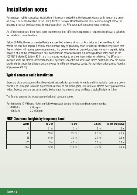
EIRP Clearance heights by frequency band<br />
Watts 10-2 m 70 cm 23 cm 13 cm and above<br />
1 2.1 m 2 m 2 m 2 m<br />
10 2.8 m 2.7 m 2.5 m 2.3 m<br />
25 3.4 m 3.3 m 2.7 m 2.5 m<br />
100 5 m 4.7 m 3.6 m 3.2 m<br />
1000 12 m 11.5 m 7.3 m 6.3 m<br />
Seite 14