75 Jahre Sonceboz 75 years Sonceboz
75 Jahre Sonceboz 75 years Sonceboz
75 Jahre Sonceboz 75 years Sonceboz

Erfolgreiche ePaper selbst erstellen
Machen Sie aus Ihren PDF Publikationen ein blätterbares Flipbook mit unserer einzigartigen Google optimierten e-Paper Software.
<strong>75</strong> <strong>Jahre</strong> <strong>Sonceboz</strong><br />
2008, p. 72<br />
The torque generates a clockwise, (c) in<br />
❹, or counter-clockwise, (b), rotation,<br />
per the principle that opposite magnet<br />
polarities on the rotor and stator attract<br />
each other. An axial ball bearing,<br />
(4), balances the attraction force between<br />
the rotor and the stator, thus<br />
maintaining the air gap (E) constant.<br />
It is worth noting that the relationship<br />
between the electric current and<br />
the torque is linear in Eq. 1 ❺. Thanks<br />
to this linear relationship, the available<br />
range of high torque dynamics is expanded<br />
offering torque boost capability.<br />
The fact that torque does not increase<br />
linearly with current at high angles<br />
in ❺ is ascribed to magnetic saturation,<br />
which depends on the magnetic<br />
properties and dimensions of the ferromagnetic<br />
parts. The torque without current<br />
is very low, thanks to a construction<br />
that minimises friction, and also to<br />
a detent torque. The detent torque is<br />
negligible over the useful stroke owing<br />
to the magnetic design. This very low<br />
residual torque helps minimising the<br />
size of the return spring, which is either<br />
required to guarantee a fail-safe operation<br />
of the system, or to return it to zero.<br />
The stroke is approximately <strong>75</strong>°,<br />
since the positions at 0° and 90° with<br />
alignment of rotor and stator magnetic<br />
patterns are equilibrium positions with<br />
no useful torque, ❺ and (d) in ❹.<br />
Without position control, the DC<br />
brushless actuator operates as an onoff<br />
actuator between two end stops<br />
within the useful stroke. In order to<br />
control position, a contactless sensor<br />
function is integrated in the same<br />
package. It features a magnet, (8) in<br />
❸, attached to the backside of the ferromagnetic<br />
yoke, (6), which generates<br />
a magnetic field sensed by a Hall-effect<br />
probe, (9). The probe is integrated in<br />
an ASIC which computes the field angular<br />
orientation and delivers an analog or<br />
digital voltage signal. This sensor principle<br />
is insensitive to temperature and<br />
assembly tolerances. The electronic<br />
components are fixed to a plastic cover,<br />
(11) in ❸, with integrated connector,<br />
(10), mounted on the overmolded stator,<br />
(12). Once the actuator is assembled on<br />
the final application, the sensor voltage<br />
characteristic can be calibrated by<br />
clamping the desired voltage value with<br />
respect to the end stops of the application.<br />
This completely cancels the tolerance<br />
stack-up of the entire assembly,<br />
thereby offering an optimum part-topart<br />
repeatability for the sensor output.<br />
Positioning times below 100 ms can be<br />
easily achieved via a conventional PID<br />
regulation scheme, which adjusts the<br />
voltage supplied by a standard H-bridge<br />
to the actuator coils. OBD compliance<br />
is guaranteed thanks to the sensor<br />
characteristics.<br />
Typical features such as fixation<br />
pattern, connector type, or 100 % waterproofness,<br />
can be adapted per the<br />
application specification. The performance<br />
is best described by the motor<br />
constant, an invariant expressed in<br />
Nm/√W that only varies with the permanent<br />
magnet grade (B r<br />
) and does not<br />
depend on the coil wire gauge and turn<br />
number, ❻. The mechanical work available<br />
for a specific current corresponds<br />
to the area underneath the torque curve<br />
❺. Connecting the actuator and application<br />
rotating shafts through a fourbar<br />
mechanical linkage or lever cam<br />
system permits the adjustment of the<br />
functional torque and stroke requirements<br />
at the application shaft. This is<br />
particularly useful in the case of a variable-geometry<br />
turbocharger, where the<br />
useful stroke may be 35°, thus maximising<br />
the torque delivered to the application<br />
shaft ❼, [5]. The same principle<br />
can be applied to throttle flaps by maximising<br />
the torque at closed position,<br />
e. g. 90°. Another benefit brought by<br />
mechanical linkages is efficient thermal<br />
decoupling between both actuator and<br />
application shafts.<br />
More compact, higher life time<br />
As integration surrounding the engine<br />
becomes increasingly complex with<br />
packaging space a scarce resource, constant<br />
effort is committed towards reducing<br />
the size of the direct-drive DC brushless<br />
actuator. Downsizing increases engine<br />
power density resulting in a smaller<br />
package volume, which will expose<br />
the actuators to higher thermal constraints.<br />
Reduction in cylinder count<br />
means new and possibly harsher vibration<br />
spectra for the sub-systems. The<br />
ability to guarantee an extended life<br />
time at temperatures above 150 °C is an<br />
enabling factor for the continuous development<br />
of new compact and robust<br />
direct-drive DC brushless actuators.<br />
References<br />
[1] Bareis, B.; Blank, T.; Deichmann, G.; Flaig, B.: Bibliothek<br />
der Technik, Vol. 270: Abgasrückführsysteme.<br />
Munich: Moderne Industrie, 2004<br />
[2] Flaig, B.; Zimmermann, F.: Elektrisches Abgasrückführventil.<br />
In: MTZ 61 (2000), No. 9 , pp. 572 – 5<strong>75</strong><br />
[3] Flaig, B.; Beyer, U.; André, M.-O.: Abgasrückführung<br />
bei Ottomotoren mit Direkteinspritzung. In:<br />
MTZ 71 (2010), No.1, pp. 34 – 40<br />
[4] André, M.-O.; Gassmann, C.; Reghenzi, P.: Torque-<br />
Motoren als Aktuatoren im Ansaug- und Abgasbereich.<br />
In: MTZ 67 (2006) No. 6, pp. 462 – 467<br />
[5] Schnell und stark. In: Automobil-Produktion, June<br />
| | ❶ Diesel EGR valve with direct-drive DC brushless<br />
actuator<br />
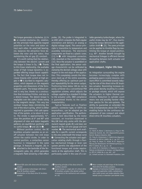
| | ❷ Variable-geometry turbocharger with directdrive<br />
DC brushless actuator<br />
| | ❸ Construction of the direct-drive DC brushless<br />
actuator<br />
32<br />
| | ❹ Operating principle of the direct-drive DC<br />
brushless actuator<br />
| | ❺ Typical torque vs. angle plot of a direct-drive<br />
DC brushless actuator (the dashed surface<br />
corresponds to the mechanical work available<br />
at 1 A)<br />
| | ❻ Motor constant and peak torque of the <strong>Sonceboz</strong><br />
direct-drive DC brushless actuators.<br />
| | ❼ Examples of mechanical linkages between actuator<br />
and application shafts: multiplication<br />
ratio (solid curves) and stroke reduction (blue<br />
dashed curve) or extension (red dashed curve).