AZ2204 Corolla TNS300 LHD - Toyota-tech.eu
AZ2204 Corolla TNS300 LHD - Toyota-tech.eu
AZ2204 Corolla TNS300 LHD - Toyota-tech.eu

Sie wollen auch ein ePaper? Erhöhen Sie die Reichweite Ihrer Titel.
YUMPU macht aus Druck-PDFs automatisch weboptimierte ePaper, die Google liebt.
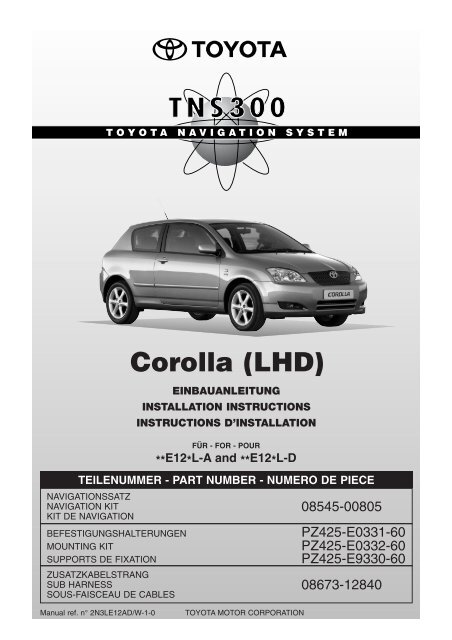
EINBAUANLEITUNG<br />
INSTALLATION INSTRUCTIONS<br />
INSTRUCTIONS D’INSTALLATION<br />
TEILENUMMER - PART NUMBER - NUMERO DE PIECE<br />
NAVIGATIONSSATZ<br />
NAVIGATION KIT 08545-00805<br />
KIT DE NAVIGATION<br />
BEFESTIGUNGSHALTERUNGEN<br />
MOUNTING KIT<br />
SUPPORTS DE FIXATION<br />
<strong>Corolla</strong> (<strong>LHD</strong>)<br />
FÜR - FOR - POUR<br />
**E12*L-A and **E12*L-D<br />
PZ425-E0331-60<br />
PZ425-E0332-60<br />
PZ425-E9330-60<br />
ZUSATZKABELSTRANG<br />
SUB HARNESS 08673-12840<br />
SOUS-FAISCEAU DE CABLES<br />
Manual ref. n° 2N3LE12AD/W-1-0<br />
TOYOTA MOTOR CORPORATION
<strong>Corolla</strong> (E12-A + E12-D)<br />
<strong>TNS300</strong><br />
VORSICHTSMASSREGELN<br />
PRECAUTIONS<br />
PRECAUTIONS<br />
LESEN SIE BITTE DIESE VORSICHTSMAßREGELN FÜR DEN EINBAU SORGFÄLTIG DURCH<br />
PLEASE READ THOROUGHLY THESE PRECAUTIONS BEFORE THE INSTALLATION<br />
PRECAUTIONS A LIRE ATTENTIVEMENT AVANT L’INSTALLATION<br />
• Darauf achten, das negative (-) Kabel von<br />
Batterieanschlüssen abzunehmen.<br />
• Be sure to disconnect the negative (-)<br />
lead from the battery terminals.<br />
• N’oubliez pas débrancher le fil négatif (-)<br />
des bornes de la batterie.<br />
• Die hintere Verkabelung oder den<br />
Kabelstrang des angezogenen Teils nicht<br />
verdrehen.<br />
• Do not pinch the rear wiring or harness<br />
in the tightened part.<br />
• Ne pincez pas la partie serrée du faisceau<br />
ou du câblage arrière.<br />
• Beim Verlegen der Kabel durch das Instrumentenbrett oder<br />
andere Verkleidungen eine Durchführungsdichtung verwenden,<br />
damit das System wasserdicht bleibt.<br />
• Beim Führen eines Kabels durch eine<br />
Öffnung das Kabel mit Klebeband<br />
schützen.<br />
• When passing the wires through the<br />
dashboard or other panels, use a<br />
grommet to ensure waterproofing.<br />
• Protect the wiring with tape when it is<br />
passed through a hole.<br />
• Lorsque vous glissez les fils à travers le tableau de bord ou<br />
d’autres panneaux, protégez-les contre l’humidité à l’aide d’un<br />
passe-fil en caoutchouc.<br />
• Protégez le cablâge avec de la mousse là où il traverse un orifice.<br />
• Beim Abnehmen der Anschlüsse die Stecker anfassen. Nie an<br />
der Verkabelung ziehen.<br />
• When disconnecting the connectors,<br />
be sure to grip the connector<br />
body. Do not tug on the wiring.<br />
• Saisissez le connect<strong>eu</strong>r proprement<br />
dit lorsque vous le débranchez. Ne<br />
tirez pas sur le câblage.<br />
Umwickeln<br />
Taping<br />
Taraudage<br />
Ist wasserdicht - OK!!<br />
waterproof - O.K. !!<br />
Etanchéité à l’eau - OK!!<br />
Nein!<br />
Stop it !<br />
Arrêtez!<br />
Durchführungstülle<br />
Grommet<br />
Passe-fil<br />
• Niemals mit Kraft an Verkabelung im Fahrz<strong>eu</strong>g ziehen. Ein<br />
festes Ziehen kann dazu führen, daß Steckverbinder auseinandergezogen<br />
werden oder daß ein Kabel oder ein Kabelstrang<br />
reißen.<br />
• Do not forcibly pull any car wiring harness.<br />
Rough tugging may result in opened<br />
connections, or a broken wire or<br />
harness.<br />
• Ne tirez pas exagérément sur les faisceaux<br />
de câbles. Vous pourriez débrancher des connexions,<br />
voire même briser le faisceau ou un de ses fils.<br />
• Überprüfen, daß Bel<strong>eu</strong>chtungsanlage,<br />
Sirene/ Signalhorn, Scheibenwischer<br />
und andere Ausrüstungen normal<br />
funktionieren.<br />
• Confirm that lamps, horn, wiper and<br />
other car accessories operate normally.<br />
• Vérifiez le bon fonctionnement des f<strong>eu</strong>x, de l’avertiss<strong>eu</strong>r,<br />
desessuie-glaces et des autres accessoires du véhicule.<br />
• Das Fahrz<strong>eu</strong>g mit Kotflügelabdeckungen,<br />
Sitzschonbezügen usw. schützen.<br />
• Protect your car with fender covers,<br />
seat and so on.<br />
• Protégez votre véhicule par des housses<br />
de siège, des housses d’aile, etc.<br />
• Beim Anziehen von Schrauben oder<br />
Muttern die vorgeschriebenen Werkz<strong>eu</strong>ge<br />
verwenden.<br />
• Use the correct tool when tightening<br />
bolts or nuts.<br />
• Serrez les boulons et les écrous avec<br />
l’outil adéquat.<br />
• Vor dem Bohren eines Lochs überprüfen,<br />
daß die Rückwand frei ist.<br />
• Before drilling a hole, check that the rear of<br />
the mounting wall is clear.<br />
• Avant de percer un trou, vérifiez s’il y a un<br />
espace libre suffisant à l’arriére de la paroi de<br />
fixation.<br />
• Sorgfältig auf das richtige Anziehen<br />
von Steckverbindern und Anschlüssen<br />
achten.<br />
• Be sure to firmly tighten connectors<br />
and terminals.<br />
• N’oubliez pas de serrer correctement<br />
les connect<strong>eu</strong>rs et des bornes.<br />
Vollständig einstecken<br />
Insert completely<br />
Insérez à fond<br />
• Vor dem Anschluß der Kabel an die<br />
Batterie die Kabelverbindungen, Kabelstrang<br />
usw. prüfen und darauf achten,<br />
daß sie richtig gesichert sind.<br />
• Before connecting the power wiring to<br />
the battery, check the wiring connections,<br />
harness, etc. to see that they are properly secured.<br />
• Avant de raccorder le fil d’alimentation à la batterie, vérifiez si<br />
les connexions des câblages, le faisceau de câbles, etc. sont<br />
correctement fixés.<br />
• Karosserie und Verkleidungen in der Nähe des Einbauortes<br />
prüfen, damit kein Schmutz oder Kratzer von den Einbauarbeiten<br />
zurückbleiben.<br />
• Check body and trim near area of installation to be certain no<br />
dirt or scratches resulted from the installation.<br />
• Vérifiez l’emplacement de l’installation ainsi que la surface<br />
avoisinante en vérifiant qu’il ne reste ni salissures ni éraflures.<br />
04-04<br />
<strong>Corolla</strong> (<strong>LHD</strong>) - 2
corolla <strong>Corolla</strong> (E12-A + E12-D)<br />
<strong>TNS300</strong><br />
EINBAU INHALTSVERZEICHNIS<br />
DER GPS-ANTENNE<br />
INSTALLATION TABLE OF CONTENTS OF THE GPS ANTENNA<br />
INSTALLATION TABLE DES MATIERES DE L’ANTENNE GPS<br />
Vorsichtsmaßregeln<br />
Precautions<br />
Précautions ..................................................................................................................................................................... 2<br />
Verwendungstabelle<br />
Application Chart<br />
Tableau des applications ................................................................................................................................................. 4<br />
Teile<br />
Component Parts<br />
Composants ................................................................................................................................................................... 5<br />
Befestigungshalterungen<br />
Mounting Brackets<br />
Supports de fixation ....................................................................................................................................................... 7<br />
Übersicht Verwendung des Einbausatzes<br />
Mounting Kit Application Overview<br />
Presentation de l’application du kit de montage ............................................................................................................. 10<br />
Benötigte Teile<br />
Required Parts<br />
Pièces ............................................................................................................................................................................. 11<br />
Verkabelung<br />
Wiring Connection<br />
Câblage ........................................................................................................................................................................... 12<br />
Einbauübersicht<br />
Installation Overview<br />
Vue d’ensemble de l’installation ..................................................................................................................................... 13<br />
Ausbau aus dem Fahrz<strong>eu</strong>g<br />
Vehicle Disassembly<br />
Démontage du véhicule .................................................................................................................................................. 14<br />
Einbau der GPS-Antenne<br />
Installation of the GPS Antenna<br />
Installation de l’antenne GPS .......................................................................................................................................... 19<br />
Einbau des Kabelstrangs<br />
Wire Harness Installation<br />
Installation du faisceau de câbles ................................................................................................................................... 22<br />
Einbau des Computers<br />
Installation of the Computer<br />
Installation de l’ordinat<strong>eu</strong>r .............................................................................................................................................. 30<br />
Einlegen der Navigation-disc<br />
Installation of Navigation Disc<br />
Installation du disque de navigation ............................................................................................................................... 37<br />
Inspektion nach dem Einbau<br />
Post-Installation Inspection<br />
Verification de l’installation ............................................................................................................................................. 37<br />
Wiedereinbau<br />
Reassembling<br />
Repose ........................................................................................................................................................................... 38<br />
<strong>Corolla</strong> (<strong>LHD</strong>) - 3<br />
04-04
p. 1/1<br />
AUDIO APPLICATION CHART<br />
TMME-CS Dev. Dept. II - March 25th, 2003<br />
<strong>Corolla</strong> **E12**-A and **E12**-D (<strong>LHD</strong> + RHD)<br />
appl. chart <strong>Corolla</strong> .xls<br />
+ ADD-ON UNIT(S)<br />
Hide-Away CD-Changer TM0461(08601-00911) Navigation System TNS200 (08545-00802)<br />
In Dash CD-Changer TM 0561(08601-00913)<br />
Navigation System <strong>TNS300</strong> (08545-00805)<br />
COMBINATION<br />
HEAD UNIT<br />
REQUIRED ADDITIONAL PARTS<br />
1 Radio/Cassette (only) Standard from factory<br />
-<br />
2 Radio/Cassette + CD-Changer Standard from factory<br />
Standard from factory . (1)<br />
F/K 08695-02800<br />
-<br />
3 Radio/Cassette + Navigation (TBT) Standard from factory . (2)<br />
Standard from factory . (2)<br />
4 Radio/Cassette + CD-Changer + Standard from factory . (2)<br />
Navigation (TBT) Standard from factory . (2)<br />
Standard from factory . (3) . (2)<br />
Standard from factory . (3) . (2)<br />
5 CD-Tuner (only) Standard from factory<br />
6 CD-Tuner + CD-Changer Standard from factory<br />
Standard from factory . (1)<br />
UDA (Unique Design Audio)<br />
7 CD-Tuner + Navigation (TBT) Standard from factory . (2)<br />
Standard from factory . (2)<br />
F/K *<br />
F/K *<br />
F/K * + F/K 08695-02800<br />
F/K * + F/K 08695-02800<br />
F/K *<br />
F/K *<br />
-<br />
F/K 08695-02800<br />
-<br />
F/K *<br />
F/K *<br />
8 CD-Tuner + CD-Changer + Standard from factory . (2)<br />
Navigation (TBT) Standard from factory . (2)<br />
Standard from factory . (3) . (2)<br />
Standard from factory . (3) . (2)<br />
F/K * + F/K 08695-02800<br />
F/K * + F/K 08695-02800<br />
F/K *<br />
F/K *<br />
9 Head unit + CD-Changer Optional from factory<br />
Optional from factory . (3)<br />
F/K 08695-02800<br />
-<br />
AVX full map navi-system<br />
*F/K: Mounting brackets PZ425-E0331-60 or PZ425-E0332-60: For correct Part Number please refer to the Mounting Kit Overview p.9. - F/K 08695-02800: In dash - Mounting kit<br />
(1): Preferred position: under the RH seat. W/o navigation: also possible under the LH seat. (2): Located under the LH seat. (3) Located under the RH seat
<strong>Corolla</strong> (E12-A + E12-D)<br />
<strong>TNS300</strong><br />
TEILE<br />
COMPONENT PARTS 08545-00805<br />
COMPOSANTS<br />
<strong>Corolla</strong> (<strong>LHD</strong>) - 5 04-04
<strong>Corolla</strong> (E12-A + E12-D)<br />
<strong>TNS300</strong><br />
Nr. Bezeichnung Menge<br />
No. Part name Quantity<br />
No. Référence Quantité<br />
COMPUTER<br />
COMPUTER 1<br />
ORDINATEUR<br />
KABELSTRANG<br />
WIRE HARNESS 1<br />
FAISCEAU DE CABLES<br />
GPS-ANTENNE<br />
GPS ANTENNA 1<br />
ANTENNE GPS<br />
COMPUTERHALTERUNG<br />
COMPUTER BRACKET 2<br />
SUPPORT DE L'ORDINATEUR<br />
BOLZEN (M5x8)<br />
BOLT (M5x8) 4<br />
BOULON (M5x8)<br />
KABELKLEMME<br />
CORD CLAMP 2<br />
AGRAFE POUR CORDON<br />
SCHAUMSTOFF<br />
FOAM 2<br />
MOUSSE<br />
KABELBINDER<br />
WIRE TIE 5<br />
LIEN POUR CABLES<br />
MASSEBLECH<br />
EARTH PLATE 1<br />
PLAQUE DE MISE A LA MASSE<br />
BUTYL-KLEBEBAND<br />
BUTYL TAPE 4<br />
RUBAN D’ISOLEMENT<br />
04-04<br />
<strong>Corolla</strong> (<strong>LHD</strong>) - 6
<strong>Corolla</strong> (E12-A + E12-D)<br />
<strong>TNS300</strong><br />
BEFESTIGUNGSHALTERUNGEN<br />
MOUNTING BRACKETS<br />
SUPPORTS DE FIXATION<br />
PZ425-E0331-60<br />
Siehe ‘Übersicht Verwendung des Einbausatzes’ (p.10)<br />
See ‘Mounting Kit Application Overview’ (p.10)<br />
Vue ‘Presentation de l’application du kit de montage’ (p.10)<br />
(a) (b) (c) (d) (e) (f)<br />
Nr. Bezeichnung Menge<br />
No. Part name Quantity<br />
No. Référence Quantité<br />
SEITENHALTERUNG<br />
(a)+(b) SIDE BRACKET 2<br />
SUPPORT LATÉRAL<br />
BEFESTIGUNGSHALTER<br />
(c) ADAPTER BRACKET 1<br />
SUPPORT DE FIXATION<br />
BOLZEN (M5x8)<br />
(d) BOLT (M5x8) 4<br />
BOULON (M5x8)<br />
BOLZEN (M8x16)<br />
(e) BOLT (M8x16) 3<br />
BOULON (M8x16)<br />
KLEBEBAND<br />
(f) TAPE 1<br />
BANDE<br />
<strong>Corolla</strong> (<strong>LHD</strong>) - 7 04-04
<strong>Corolla</strong> (E12-A + E12-D)<br />
<strong>TNS300</strong><br />
BEFESTIGUNGSHALTERUNGEN<br />
MOUNTING BRACKETS<br />
SUPPORTS DE FIXATION<br />
PZ425-E0332-60<br />
Siehe ‘Übersicht Verwendung des Einbausatzes’ (p.10)<br />
See ‘Mounting Kit Application Overview’ (p.10)<br />
Vue ‘Presentation de l’application du kit de montage’ (p.10)<br />
(a) (b) (c) (d) (e) (f)<br />
Nr. Bezeichnung Menge<br />
No. Part name Quantity<br />
No. Référence Quantité<br />
SEITENHALTERUNG<br />
(a)+(b) SIDE BRACKET 2<br />
SUPPORT LATÉRAL<br />
BEFESTIGUNGSHALTER<br />
(c) ADAPTER BRACKET 1<br />
SUPPORT DE FIXATION<br />
BOLZEN (M5x8)<br />
(d) BOLT (M5x8) 4<br />
BOULON (M5x8)<br />
BOLZEN (M8x16)<br />
(e) BOLT (M8x16) 3<br />
BOULON (M8x16)<br />
KLEBEBAND<br />
(f) TAPE 1<br />
BANDE<br />
04-04<br />
<strong>Corolla</strong> (<strong>LHD</strong>) - 8
<strong>Corolla</strong> (E12-A + E12-D)<br />
<strong>TNS300</strong><br />
BEFESTIGUNGSHALTERUNGEN<br />
MOUNTING BRACKETS<br />
SUPPORTS DE FIXATION<br />
PZ425-E9330-60<br />
Siehe ‘Übersicht Verwendung des Einbausatzes’ (p.10)<br />
See ‘Mounting Kit Application Overview’ (p.10)<br />
Vue ‘Presentation de l’application du kit de montage’ (p.10)<br />
(a) (b) (c) (d) (e) (f)<br />
Nr. Bezeichnung Menge<br />
No. Part name Quantity<br />
No. Référence Quantité<br />
SEITENHALTERUNG<br />
(a)+(b) SIDE BRACKET 2<br />
SUPPORT LATÉRAL<br />
BEFESTIGUNGSHALTER<br />
(c) ADAPTER BRACKET 1<br />
SUPPORT DE FIXATION<br />
BOLZEN (M5x8)<br />
(d) BOLT (M5x8) 4<br />
BOULON (M5x8)<br />
BOLZEN (M8x16)<br />
(e) BOLT (M8x16) 3<br />
BOULON (M8x16)<br />
KLEBEBAND<br />
(f) TAPE 1<br />
BANDE<br />
<strong>Corolla</strong> (<strong>LHD</strong>) - 9 04-04
<strong>Corolla</strong> (E12-A + E12-D)<br />
<strong>TNS300</strong><br />
ÜBERSICHT VERWENDUNG DES EINBAUSATZES<br />
MOUNTING KIT APPLICATION OVERVIEW<br />
PRESENTATION DE L'APPLICATION DU KIT DE MONTAGE<br />
Fahrz<strong>eu</strong>gmodell Modellcode Teilenummer Montage siehe<br />
Vehicle model Model code Part Number For mounting see<br />
Modèle de véhicule Code modèle Numéro de pièce Pour l'installation, voir<br />
Kombi von TMC<br />
Limousine von TMC Seite 30<br />
Wagon by TMC **E12*L-AW**** Page 30<br />
Sedan by TMC **E12*L-AE**** Page 30<br />
Wagon de TMC<br />
PZ425-E0331-60<br />
or<br />
Schrägheck von TMUK (3-Türer + 5-Türer)<br />
PZ425-E9330-60 (*)<br />
Kombi von TMMT<br />
Seite 32<br />
**E12*L-DG****<br />
Hatch back by TMUK (3-doors + 5-doors)<br />
Page 32<br />
**E12*L-DH****<br />
Wagon by TMMT<br />
Page 32<br />
**E12*L-DW****<br />
Hatch back (3 portes + 5 portes) de TMUK<br />
Wagon de TMMT<br />
Schrägheck von TMC (5-Türer) Seite 34<br />
Hatch back by TMC (5-doors) **E12*L-AH**** PZ425-E0332-60 Page 34<br />
Hatch back (5 portes) de TMC Page 34<br />
(*)<br />
HINWEIS<br />
Alle von TMMT produzierten Fahrz<strong>eu</strong>ge<br />
müssen ab Produktionsdatum<br />
Februar 2004 mit Seitenhalterung<br />
(a) (PZ425-E9330-60) ausgestattet<br />
sein.<br />
(*)<br />
NOTE<br />
The side bracket (a) (PZ425-E9330-<br />
60) has to be applied to all TMMT produced<br />
vehicles with production date<br />
as of February 2004.<br />
(*)<br />
REMARQUE<br />
Le support latéral (a) (PZ425-<br />
E9330-60) doit être appliqué sur tous<br />
les véhiculés fabriqués par TMMT<br />
dont la date de production est à partir<br />
de février 2004.<br />
04-04<br />
<strong>Corolla</strong> (<strong>LHD</strong>) - 10
<strong>Corolla</strong> (E12-A + E12-D)<br />
<strong>TNS300</strong><br />
BENÖTIGTE EINBAU DER TEILE GPS-ANTENNE<br />
REQUIRED INSTALLATION PARTS OF THE GPS ANTENNA<br />
PIECES INSTALLATION DE L’ANTENNE GPS<br />
DVD-ROM<br />
Separat zu bestellen.<br />
Die für das <strong>TNS300</strong> Navigationssystem erhältlichen DVD-ROM entnehmen Sie bitte der Liste (Zugang zu Zubehör).<br />
To be ordered separately.<br />
Please refer to the list of available DVD-ROM for <strong>TNS300</strong> Navigation System (Access to accessories).<br />
A commander séparément.<br />
Reportez-vous à la liste des DVD-ROM disponibles pour le Système de navigation <strong>TNS300</strong> (Accès aux accessoires).<br />
BEDIENUNGSANLEITUNG<br />
OWNER’S MANUAL<br />
MODE D’EMPLOI<br />
Separat zu bestellen.<br />
To be ordered separately.<br />
A commander séparément.<br />
ZUSATZKABELSTRANG (NUR FÜR FAHRZEUGE OHNE LENKUNGSSCHALTER)<br />
SUB HARNESS (ONLY FOR VEHICLES WITHOUT STEERING SWITCH) 08673-12840<br />
SOUS-FAISCEAU DE CABLES (UNIQUEMENT POUR VEHICULES SANS COMMUTATEUR AU VOLANT)<br />
<strong>Corolla</strong> (<strong>LHD</strong>) - 11 04-04
<strong>Corolla</strong> (E12-A + E12-D)<br />
<strong>TNS300</strong><br />
EINBAU VERKABELUNG DER GPS-ANTENNE<br />
INSTALLATION WIRING CONNECTION OF THE GPS ANTENNA<br />
INSTALLATION CABLAGE DE L’ANTENNE GPS<br />
AUDIO-EINHEIT MIT MULTI-DISPLAY<br />
AUDIO UNIT WITH MULTI-DISPLAY<br />
APPAREIL AUDIO AVEC AFFICHAGE MULTIFONCTION<br />
Anschlußverfahren / Connection Method / Méthode de raccordement :<br />
Ohne Lenkungsschalter<br />
Without steering switch<br />
Sans communicat<strong>eu</strong>r au volant<br />
12P<br />
Verbindungsstecker<br />
Splicing Connector<br />
Connect<strong>eu</strong>r de raccordement<br />
Audio-Einheit mit Multi-Display<br />
Audio unit with multi display<br />
Appareil audio avec affichage multifonction<br />
10P<br />
8P<br />
Zusatzkabelstrang<br />
Sub harness<br />
Sous-faisceau au de cables<br />
(TX- -Kabel)<br />
(TX- Wire)<br />
(Fil du TX-)<br />
(TX+ -Kabel)<br />
(TX+ Wire)<br />
(Fil du TX+)<br />
GPS-Antenne<br />
GPS Antenna<br />
Antenne GPS<br />
Fahrz<strong>eu</strong>gkabelstrang<br />
Vehicle Wire harness<br />
Faisceau de câbles du véhicule<br />
18P<br />
1P<br />
8P<br />
13P<br />
Verbindungsstecker (TX+ -Kabel)<br />
Splicing Connector (TX+ Wire)<br />
Connect<strong>eu</strong>r de raccordement (fil du TX+)<br />
Verbindungsstecker (TX- -Kabel)<br />
Splicing Connector (TX- Wire)<br />
Connect<strong>eu</strong>r de raccordement (Fil du TX-)<br />
Verbindungsstecker<br />
Splicing Connector<br />
Connect<strong>eu</strong>r de raccordement<br />
Nr. Bezeichnung Menge<br />
No.<br />
No.<br />
Part name<br />
Référence<br />
Quantity<br />
Quantité<br />
COMPUTER<br />
COMPUTER 1<br />
ORDINATEUR<br />
KABELSTRANG<br />
WIRE HARNESS 1<br />
FAISCEAU DE CABLES<br />
ANTENNENKABEL<br />
ANTENNA CORD 1<br />
CORDON DE L’ANTENNE<br />
KABELSTRANG-GESCHWINDIGKEIT<br />
WIRE HARNESS SPEED SENSOR WIRE 1<br />
FAISCEAU DE CABLES-VITESSE<br />
KABELSTRANG RÜCKFAHRSENSORKABEL<br />
WIRE HARNESS REVERSE SENSOR WIRE 1<br />
FIL DU DETECTEUR DE MARCHE ARRIERE DU FAISCEAU DE CABLES<br />
04-04<br />
<strong>Corolla</strong> (<strong>LHD</strong>) - 12
<strong>Corolla</strong> (E12-A + E12-D)<br />
<strong>TNS300</strong><br />
EINBAUÜBERSICHT<br />
INSTALLATION OVERVIEW<br />
VUE D’ENSEMBLE DE L’INSTALLATION<br />
GPS-Antenne<br />
GPS Antenna<br />
Antenne GPS<br />
Verbindungsstecker<br />
Splicing Connector<br />
Connect<strong>eu</strong>r de raccordement<br />
(TX- -Kabel)<br />
(TX- Wire)<br />
(Fil du TX-)<br />
(TX+ -Kabel)<br />
(TX+ Wire)<br />
(Fil du TX+)<br />
Verbindungsstecker<br />
Splicing Connector<br />
Connect<strong>eu</strong>r de<br />
raccordement<br />
Überschüssiger Hauptkabelstrang<br />
Excess main wire harness<br />
Longu<strong>eu</strong>r excédentaire du faisceau<br />
de cäbles principal<br />
Überschüssiger Antennenkabel<br />
Excess antenna wire<br />
Longu<strong>eu</strong>r excédentaire du cordon<br />
de l’antennede l’Antenne<br />
KABELSTRANG-GESCHWINDIGKEIT (VIOLETT/WEISS)<br />
WIRE HARNESS SPEED LINE (VIOLET/WHITE)<br />
FAISCEAU DE CABLES-VITESSE (VIOLET/BLANC)<br />
KABELSTRANG<br />
WIRE HARNESS<br />
FAISCEAU DE CABLE<br />
ANTENNENKABEL<br />
ANTENNA CORD<br />
CORDON DE L’ANTENNE<br />
KABELSTRANG RÜCKFAHRSENSORKABEL (ROT/BLAU)<br />
WIRE HARNESS REVERSE SENSOR WIRE (RED/BLUE)<br />
FIL DU DETECTEUR DE MARCHE ARRIERE DU FAISCEAU DE CABLES<br />
(ROUGE/BLEU)<br />
<strong>Corolla</strong> (<strong>LHD</strong>) - 13 04-04
<strong>Corolla</strong> (E12-A + E12-D)<br />
<strong>TNS300</strong><br />
EINBAU AUSBAU DER AUS GPS-ANTENNE<br />
DEM FAHRZEUG<br />
INSTALLATION VEHICLE DISASSEMBLY OF THE GPS ANTENNA<br />
INSTALLATION DEMONTAGE DU DE VEHICULE L’ANTENNE GPS<br />
1. Einstiegsabdeckung (L) der Vordertür<br />
entfernen.<br />
: Clip (3x)<br />
: Haken (5x)<br />
1. Remove the front door scuff plate<br />
(L).<br />
: Clip (3x)<br />
: Hook (5x)<br />
1. Enlevez la plaque de protection de la<br />
porte avant (G).<br />
: Clip (3x)<br />
: Crochet (5x)<br />
Abb. 1 - Fig. 1<br />
2. Die Fußstütze entfernen.<br />
: Clip (2x)<br />
2. Remove the foot rest .<br />
: Clip (2x)<br />
2. Enlevez le repose-pied .<br />
: Clip (2x)<br />
Abb. 2 - Fig. 2<br />
3. Die Windlaufseitenverkleidung (L)<br />
entfernen.<br />
: Mutter (1x)<br />
: Haken (2x)<br />
3. Remove the kick panel (L).<br />
: Nut (1x)<br />
: Hook (2x)<br />
3. Enlevez le panneau du carter de roue<br />
(G).<br />
: Ecrou (1x)<br />
: Crochet (2x)<br />
Abb. 3 - Fig. 3<br />
04-04<br />
<strong>Corolla</strong> (<strong>LHD</strong>) - 14
<strong>Corolla</strong> (E12-A + E12-D)<br />
<strong>TNS300</strong><br />
4. Den Aschenbecher entfernen.<br />
4. Remove the ashtray .<br />
4. Enlevez le tiroir du cendrier .<br />
Abb. 4 - Fig. 4<br />
BEI SCHALTGETRIEBE<br />
FOR MANUAL TRANSMISSION<br />
POUR BOITE MANUELLE<br />
5. Den Schaltknauf entfernen.<br />
5. Remove the shift knob .<br />
5. Enlevez le bouton du levier .<br />
BEI ALLEN MODELLEN<br />
FOR ALL MODELS<br />
TOUS MODELES<br />
6. Die Konsolenabdeckung entfernen.<br />
: Haken (6x)<br />
Abb. 5 - Fig. 5<br />
ACHTUNG<br />
An den schraffierten Bereichen die<br />
Schutzklebebänder anbringen. Die<br />
Teile unbedingt vorsichtig entfernen,<br />
um diesen Abschnitt nicht zu beschädigen.<br />
6. Remove the console panel .<br />
: Hook (6x)<br />
CAUTION<br />
Put the protective tapes on the shaded<br />
areas. Be sure to remove the parts<br />
carefully not to damage the section.<br />
6. Enlevez le panneau de la console .<br />
: Crochet (6x)<br />
ATTENTION<br />
Placez du ruban de protection sur les<br />
zones ombrées. Veillez à déposer délicatement<br />
les pièces afin de ne pas<br />
endommager cette zone.<br />
<strong>Corolla</strong> (<strong>LHD</strong>) - 15 04-04
<strong>Corolla</strong> (E12-A + E12-D)<br />
<strong>TNS300</strong><br />
FÜR MODELLE MIT<br />
AUTOMATISCHER KLIMAANLAGE<br />
FOR AUTO A/C MODELS<br />
POUR MODELES AVEC<br />
CLIMATISATION AUTOMATIQUE<br />
7. Die Heizungsreglerverkleidung entfernen.<br />
: Clip (4x)<br />
: Haken (4x)<br />
Abb. 6 - Fig. 6<br />
7. Enlevez le panneau de commande du chauffage .<br />
: Clip (4x)<br />
: Crochet (4x)<br />
ATTENTION<br />
Placez du ruban de protection sur les zones ombrées.<br />
Veillez à déposer délicatement les pièces afin de ne pas<br />
endommager cette zone.<br />
ACHTUNG<br />
An den schraffierten Bereichen die<br />
Schutzklebebänder anbringen. Die<br />
Teile unbedingt vorsichtig entfernen,<br />
um diesen Abschnitt nicht zu beschädigen.<br />
7. Remove the heater control panel .<br />
: Clip (4x)<br />
: Hook (4x)<br />
CAUTION<br />
Put the protective tapes on the shaded<br />
areas. Be sure to remove the parts<br />
carefully not to damage the section.<br />
8. Enlevez le bouton de règlage et le panneau de commande<br />
du chauffage .<br />
: Vis(1x)<br />
: Clip (4x)<br />
: Crochet (4x)<br />
04-04<br />
Abb. 7 - Fig. 7<br />
ATTENTION<br />
Placez du ruban de protection sur les zones ombrées.<br />
Veillez à déposer délicatement les pièces afin de ne pas<br />
endommager cette zone.<br />
<strong>Corolla</strong> (<strong>LHD</strong>) - 16<br />
FÜR MODELLE MIT<br />
MANUELLER KLIMAANLAGE<br />
FOR MANUAL A/C MODELS<br />
POUR MODELES AVEC<br />
CLIMATISATION MANUELLE<br />
8. Den Reglerknopf und die<br />
Heizungsreglerverkleidung entfernen.<br />
: Schraube (1x)<br />
: Clip (4x)<br />
: Haken (4x)<br />
ACHTUNG<br />
An den schraffierten Bereichen die<br />
Schutzklebebänder anbringen. Die<br />
Teile unbedingt vorsichtig entfernen,<br />
um diesen Abschnitt nicht zu<br />
beschädigen.<br />
8. Remove the knob and the heater<br />
control panel .<br />
: Screw (1x)<br />
: Clip (4x)<br />
: Hook (4x)<br />
CAUTION<br />
Put the protective tapes on the shaded<br />
areas. Be sure to remove the parts<br />
carefully not to damage the section.
corolla <strong>Corolla</strong> (E12-A + E12-D)<br />
<strong>TNS300</strong><br />
9. Den CD-Tuner (Kassettendeck) mit<br />
Multi-Display entfernen.<br />
: Bolzen (4x)<br />
: Clip (2x)<br />
: Haken (4x)<br />
ACHTUNG<br />
An den schraffierten Bereichen die<br />
Schutzklebebänder anbringen. Die<br />
Teile unbedingt vorsichtig entfernen,<br />
um diesen Abschnitt nicht zu beschädigen.<br />
Abb. 8 - Fig. 8<br />
9. Enlevez l’autoradio (cassette) avec lect<strong>eu</strong>r CD et affichage<br />
multifonction .<br />
: Boulon (4x)<br />
: Clip (2x)<br />
: Crochet (4x)<br />
ATTENTION<br />
Placez du ruban de protection sur les zones ombrées.<br />
Veillez à déposer délicatement les pièces afin de ne pas<br />
endommager cette zone.<br />
9. Remove the CD (Cassette) tuner with<br />
multi display .<br />
: Bolt (4x)<br />
: Clip (2x)<br />
: Hook (4x)<br />
CAUTION<br />
Put the protective tapes on the shaded<br />
areas. Be sure to remove the parts<br />
carefully not to damage the section.<br />
10. Abdeckung der Instrumentenbaugruppe<br />
entfernen.<br />
: Clip (1x)<br />
: Haken (7x)<br />
10. Remove the meter cluster panel .<br />
: Clip (1x)<br />
: Hook (7x)<br />
10. Enlevez le panneau de la console du<br />
tableau de bord .<br />
: Clip (1x)<br />
: Crochet (7x)<br />
Abb. 9 - Fig. 9<br />
<strong>Corolla</strong> (<strong>LHD</strong>) - 17 04-04
<strong>Corolla</strong> (E12-A + E12-D)<br />
<strong>TNS300</strong><br />
11. Das Handschuhfach entfernen.<br />
: Haken (2x)<br />
11. Remove the glove box .<br />
: Hook (2x)<br />
11. Enlevez la boîte à gants .<br />
: Crochet (2x)<br />
Abb. 10 - Fig. 10<br />
12. Den Fahrersitz entfernen.<br />
: Bolzen (4x)<br />
: Abdeckung (2x)<br />
12. Remove the driver seat .<br />
: Bolt (4x)<br />
: Cover (2x)<br />
12. Enlevez le siège du conduct<strong>eu</strong>r .<br />
: Boulon(4x)<br />
: Couvercle (2x)<br />
Abb. 11 - Fig. 11<br />
04-04<br />
<strong>Corolla</strong> (<strong>LHD</strong>) - 18
<strong>Corolla</strong> (E12-A + E12-D)<br />
<strong>TNS300</strong><br />
EINBAU DER GPS-ANTENNE<br />
INSTALLATION OF THE GPS ANTENNA<br />
INSTALLATION DE L’ANTENNE GPS<br />
1. Das Schaumstoff in 4 große, 8 mittlere<br />
und 8 kleine Stücke schneiden, wie<br />
in der Abbildung gezeigt.<br />
1. Cut the foam into 4 large pieces, 8<br />
middle pieces and 8 small pieces as<br />
shown in the illustration.<br />
1. Découpez la mousse en 4 grands<br />
morceau, 8 moyens et 8 petits morceaux,<br />
de la manière illustrée.<br />
4x<br />
8x<br />
8x<br />
Abb. 12 - Fig. 12<br />
2. Das Klebeband in 2 gleich große<br />
Stücke schneiden.<br />
2. Cut the butyl tape into 2 equal sized<br />
pieces.<br />
2. Coupez la bande adhésive en 2<br />
parts égales.<br />
Abb. 13 - Fig. 13<br />
<strong>Corolla</strong> (<strong>LHD</strong>) - 19 04-04
<strong>Corolla</strong> (E12-A + E12-D)<br />
<strong>TNS300</strong><br />
GPS-Antenne<br />
GPS Antenna<br />
Antenne GPS<br />
Abb. 14 - Fig. 14<br />
3.<br />
a) Die Schutzfolie von der Rückseite des<br />
Masseblechs entfernen und Klebeband<br />
anbringen wie gezeigt.<br />
b) Die Klebebandstücke an der Klebeseite<br />
der Masseplatte anbringen.<br />
3.<br />
a) Remove the release paper of the earth<br />
plate and attach the butyl tape as<br />
shown.<br />
b) Apply the tapes to the adhesive side<br />
of the earth plate .<br />
3.<br />
a) Retirez le support en papier de la<br />
plaque de mise à la masse et fixez<br />
le ruban d’isolement de la manière<br />
illustrée.<br />
b) Fixez les bandes au côté adhésif de<br />
la plaque de mise à la masse .<br />
4.<br />
a) Das Masseblech an der Instrumentenbaugruppe<br />
befestigen und die<br />
GPS Antenne auf das Massebech<br />
montieren wie gezeigt.<br />
b) Das Antennenkabel mit Schaumstoff<br />
(3x) befestigen.<br />
ACHTUNG<br />
Die Oberfläche der Einbauposition<br />
vor dem Anbringen der Masseplatte<br />
unbedingt reinigen.<br />
04-04<br />
Mitte<br />
Centre<br />
Abb. 15 - Fig. 15<br />
<strong>Corolla</strong> (<strong>LHD</strong>) - 20<br />
4.<br />
a) Attach the earth plate to the meter<br />
cluster panel as shown and mount the<br />
GPS antenna to the earth plate .<br />
b) Fix the antenna cord using foam<br />
(3x).<br />
CAUTION<br />
Make sure to clean the installation<br />
position surface before attaching the<br />
earth plate .<br />
4.<br />
a) Fixez la plaque de mise à la masse<br />
sur le panneau de la console du tableau<br />
de bord de la manière illustrée, puis<br />
fixez l’antenne GPS à la plaque de<br />
mise à la masse .<br />
b) Fixez le cordon de l’antenne à l’aide<br />
de la mousse (3x).<br />
ATTENTION<br />
Avant de fixer la plaque de mise à la<br />
masse , veillez à nettoyer préalablement<br />
la surface d'installation.
<strong>Corolla</strong> (E12-A + E12-D)<br />
<strong>TNS300</strong><br />
5.<br />
a) Das Antennenkabel verlegen wie in<br />
der Abbildung gezeigt.<br />
b) Gemäß Abbildung die Instrumentengruppe<br />
wieder in ihre ursprüngliche<br />
Position bringen, ohne dass das GPS-<br />
Antennenkabel an der Instrumententafel<br />
reibt.<br />
ACHTUNG<br />
Darauf achten, dass die GPS-Antenne<br />
nicht von der Masseplatte geschoben<br />
wird.<br />
Abb. 16 - Fig. 16<br />
5.<br />
a) Route the antenna cord as shown in<br />
the illustration.<br />
b) According to the illustration, return the<br />
meter cluster to its original position,<br />
without rubbing the GPS antenna<br />
against the instrument panel.<br />
CAUTION<br />
Be careful not to slip away the GPS<br />
antenna from the earth plate .<br />
5.<br />
a) Acheminez le cordon de l’antenne<br />
de la manière illustrée.<br />
b) En vous reportant à l’illustration, replacez<br />
la console centrale sur sa position<br />
d’origine en veillant à ce que l’antenne<br />
GPS ne frotte pas contre le<br />
tableau de bord.<br />
ATTENTION<br />
Veillez à ce que l’antenne GPS ne glisse<br />
pas et ne se détache pas de la plaque<br />
de mise à la masse .<br />
<strong>Corolla</strong> (<strong>LHD</strong>) - 21 04-04
<strong>Corolla</strong> (E12-A + E12-D)<br />
<strong>TNS300</strong><br />
EINBAU DES KABELSTRANGS<br />
WIRE HARNESS INSTALLATION<br />
INSTALLATION DU FAISCEAU DE CABLES<br />
1. Den Kabelstrang und das Antennenkabel<br />
verlegen, wie in der<br />
Abbildung gezeigt.<br />
1. Route the wire harness and antenna<br />
cord as shown in the illustration.<br />
1. Acheminez le faisceau de câbles et<br />
le cordon de l’antenne de la manière<br />
illustrée.<br />
Abb. 17 - Fig. 17<br />
18P<br />
2. Die in der Abbildung gezeigten Verbindungsstecker<br />
sind die fahrz<strong>eu</strong>gseitigen<br />
Stecker, die zu verbinden sind.<br />
2. The connectors shown in the illustration<br />
are the vehicle side connectors to be<br />
spliced.<br />
2. Les connect<strong>eu</strong>rs illustrés sont c<strong>eu</strong>x à<br />
raccorder du côté du véhicule.<br />
10P<br />
Abb. 18 - Fig. 18<br />
04-04<br />
<strong>Corolla</strong> (<strong>LHD</strong>) - 22
corolla <strong>Corolla</strong> (E12-A + E12-D)<br />
<strong>TNS300</strong><br />
l ANLEITUNG FÜR KABEL VERBIN-<br />
DUNGSSTECKER<br />
l WIRE SPLICING CONNECTOR<br />
INSTRUCTIONS<br />
l INSTRUCTIONS D’UTILISATION DU<br />
CONNECTEUR DE RACCORDEMENT<br />
Abb. 19 - Fig. 19<br />
3.<br />
a) Die entsprechende Menge Klebeband<br />
vom Fahrz<strong>eu</strong>gkabelstrang, der angeschlossen<br />
werden soll, entfernen.<br />
b) Den Fahrz<strong>eu</strong>gkabelstrang , der<br />
angeschlossen werden soll, fest in den<br />
Führungsschlitz legen.<br />
c) Nach Einlegen des Fahrz<strong>eu</strong>gkabelstrangs<br />
in den Führungsschlitz den<br />
Steckverbinder schließen und fest<br />
mit einer Zange zusammendrücken,<br />
bis er einrastet.<br />
3.<br />
a) Remove appropriate amount of tape<br />
wrapping the vehicle side harness to be<br />
connected.<br />
b) Insert the vehicle harness to be connected<br />
securely into the guide slit.<br />
c) After inserting the vehicle side harness<br />
into the guide slit, fix the splicing connector<br />
, and lock it securely using a<br />
plier until the connector clicks.<br />
3.<br />
a) Retirez la longu<strong>eu</strong>r de bande voulue<br />
autour du faisceau de câbles du véhicule<br />
à raccorder.<br />
b) Insérez solidement dans la fente de<br />
guidage le faisceau de câbles à raccorder.<br />
c) Après avoir inséré le faisceau de<br />
câbles du véhicule dans la fente de guidage,<br />
fixez le connect<strong>eu</strong>r de raccordement<br />
et serrez-le fermement à l'aide<br />
d'une pince jusqu'à ce qu'il émette<br />
un déclic.<br />
<strong>Corolla</strong> (<strong>LHD</strong>) - 23 04-04
<strong>Corolla</strong> (E12-A + E12-D)<br />
<strong>TNS300</strong><br />
l ANSCHLIESSEN DES TX-KABELS<br />
UND DES GESCHWINDIGKEITSSEN-<br />
SORS<br />
l TX WIRE + SPEED SENSOR CON-<br />
NECTION<br />
l RACCORDEMENT DU FIL DU TX ET<br />
DU DETECTEUR DE VITESSE<br />
18P<br />
Erhöhung<br />
Tab<br />
Onglet<br />
TX- (gelb/zwarz)<br />
TX- (yellow/black)<br />
TX- (jaune/noir)<br />
Abb. 20 - Fig. 20<br />
ANSICHT KABELSEITE<br />
WIRE SIDE VIEW<br />
VUE COTE FILS<br />
TX +<br />
TX -<br />
TX+ (gelb)<br />
TX+ (yellow)<br />
TX+ (jaune)<br />
4.<br />
a) Tournez le connect<strong>eu</strong>r de façon à ce que les fils soient dirigés<br />
vers le haut.<br />
b) Raccordez le fil du détect<strong>eu</strong>r TX+ (jaune) du faisceau de<br />
câbles au connect<strong>eu</strong>r à 18 pôles, troisième alvéole de la<br />
rangée supéri<strong>eu</strong>re à partir de la droite.<br />
c) Raccordez le fil du détect<strong>eu</strong>r TX- (jaune/noir) du faisceau<br />
de câbles au connect<strong>eu</strong>r à 18 pôles, troisième alvéole<br />
de la rangée inféri<strong>eu</strong>re à partir de la droite.<br />
d) Raccordez le fil du détect<strong>eu</strong>r de vitesse (violet/blanc) du<br />
faisceau de câbles au connect<strong>eu</strong>r à 18 pôles, troisième<br />
alvéole de la rangée inféri<strong>eu</strong>re, à partir de la gauche.<br />
MIT LENKUNGSSCHALTER<br />
WITH STEERING SWITCH<br />
AVEC COMMUTATEUR AU VOLANT<br />
4.<br />
a) Den Stecker so drehen, daß die Kabel<br />
auf Sie Weisen und die Erhöhung sich<br />
oben befindet.<br />
b) Das TX(+)-Kabel (gelb) der<br />
Kabelstrang an dem Kabel in der<br />
dritte Position von rechts in der oberen<br />
Reihe anschließen.<br />
c) Das TX(-)-Kabel (gelb/schwarz) der<br />
Kabelstrang an dem Kabel in der<br />
dritte Position von rechts in der unteren<br />
Reihe anschließen.<br />
d) Das Geschwindigkeitssensorkabel<br />
(violett/weiß) der Kabelstrang an<br />
dem Kabel in der dritte Position von<br />
links in der unteren Reihe anschließen.<br />
4.<br />
a) Turn the connector so that the wire face<br />
you and the tab is on top.<br />
b) Connect the TX(+) wire (yellow) of the<br />
wire harness to the wire of the third<br />
position from the right side of the top<br />
row.<br />
c) Connect the TX(-) wire (yellow/black) of<br />
the wire harness to the wire of the<br />
third position from the right side of the<br />
bottom row.<br />
d) Connect the speed sensor wire (violet/white)<br />
of the wire harness to the<br />
wire of the third position from the left<br />
side of the bottom row.<br />
04-04<br />
<strong>Corolla</strong> (<strong>LHD</strong>) - 24
<strong>Corolla</strong> (E12-A + E12-D)<br />
<strong>TNS300</strong><br />
12P<br />
Erhöhung<br />
Tab<br />
Onglet<br />
TX+ (gelb)<br />
TX+ (yellow)<br />
TX+ (jaune)<br />
Abb. 21 - Fig. 21<br />
ANSICHT KABELSEITE<br />
WIRE SIDE VIEW<br />
VUE COTE FILS<br />
TX +<br />
TX- (gelb/zwarz)<br />
TX- (yellow/black)<br />
TX- (jaune/noir)<br />
12P<br />
TX -<br />
OHNE LENKUNGSSCHALTER<br />
WITHOUT STEERING SWITCH<br />
SANS COMMUTATEUR AU VOLANT<br />
5.<br />
a) Den Stecker so drehen, daß die Kabel<br />
auf Sie Weisen und die Erhöhung sich<br />
oben befindet.<br />
b) Den 12-Stift-Stecker des Zusatzkabelstrangs<br />
mit dem fahrz<strong>eu</strong>gseitigen<br />
Stecker verbinden.<br />
c) Das TX(-)-Kabel (gelb/schwarz) der<br />
Kabelstrang an dem Kabel in der<br />
vierte Position von links in der unteren<br />
Reihe anschließen.<br />
d) Das TX(+)-Kabel (gelb) der Kabelstrang<br />
an dem Kabel in der dritte Position<br />
von links in der unteren Reihe<br />
anschließen.<br />
5.<br />
a) Turn the connector so that the wire face<br />
you and the tab is on top.<br />
b) Connect the 12P connecter of the sub<br />
harness to the vehicle side connector.<br />
c) Connect the TX- sensor wire (yellow/<br />
black) of the wire harness to the wire<br />
of the fourth position from the left side of<br />
the bottom row.<br />
d) Connect the TX+ sensor wire (yellow) of<br />
the wire harness to the wire of the<br />
third position from the left side of the<br />
bottom row.<br />
5.<br />
a) Tournez le connect<strong>eu</strong>r de façon à ce<br />
que les fils soient dirigés vers le haut.<br />
b) Raccordez le connect<strong>eu</strong>r à 12 pôles du<br />
sous-faisceau de câbles au connect<strong>eu</strong>r<br />
du côté véhicule.<br />
c) Raccordez le fil du détect<strong>eu</strong>r TX-<br />
(jaune/noir) du faisceau de câbles au<br />
connect<strong>eu</strong>r à 12 pôles, quatrième<br />
alvéole de la rangée inféri<strong>eu</strong>re à partir<br />
de la gauche.<br />
d) Raccordez le fil du détect<strong>eu</strong>r TX+<br />
(jaune) du faisceau de câbles au<br />
connect<strong>eu</strong>r à 12 pôles, troisième alvéole<br />
de la rangée inféri<strong>eu</strong>re à partir de la<br />
gauche.<br />
<strong>Corolla</strong> (<strong>LHD</strong>) - 25 04-04
<strong>Corolla</strong> (E12-A + E12-D)<br />
<strong>TNS300</strong><br />
18P<br />
Erhöhung<br />
Tab<br />
Onglet<br />
Abb. 22 - Fig. 22<br />
ANSICHT KABELSEITE<br />
WIRE SIDE VIEW<br />
VUE COTE FILS<br />
OHNE LENKUNGSSCHALTER<br />
WITHOUT STEERING SWITCH<br />
SANS COMMUTATEUR AU VOLANT<br />
6.<br />
a) Den Stecker so drehen, daß die Kabel<br />
auf Sie Weisen und die Erhöhung sich<br />
oben befindet.<br />
b) Das Geschwindigkeitssensorkabel<br />
(violett/weiß) der Kabelstrang an<br />
dem Kabel in der dritte Position von<br />
links in der unteren Reihe anschließen.<br />
6.<br />
a) Turn the connector so that the wire face<br />
you and the tab is on top.<br />
b) Connect the speed sensor wire (violet/white)<br />
of the wire harness to the<br />
wire of the third position from the left<br />
side of the bottom row.<br />
6.<br />
a) Tournez le connect<strong>eu</strong>r de façon à ce<br />
que les fils soient dirigés vers le haut.<br />
b) Raccordez le fil du détect<strong>eu</strong>r de vitesse<br />
(violet/blanc) du faisceau de câbles<br />
au connect<strong>eu</strong>r à 18 pôles, troisième<br />
alvéole de la rangée inféri<strong>eu</strong>re, à partir<br />
de la gauche.<br />
Abb. 23 - Fig. 23<br />
Anschlusskasten<br />
Junction box<br />
Boîtier de<br />
raccordement<br />
10P<br />
7.<br />
a) Den 10 Stift-Stecker lösen.<br />
b) Den Rückfahrsensorkabel (rot/blau)<br />
des Kabelstrangs verlegen wie gezeigt<br />
und mit Schaumstoff (5x) befestigen.<br />
7.<br />
a) Disconnect the 10P connector.<br />
b) Route the reverse sensor wire<br />
(red/blue) as shown in the illustration,<br />
and secure the reverse sensor<br />
wire using foam (5x).<br />
7.<br />
a) Débranchez le connect<strong>eu</strong>r à 10 pôles.<br />
b) Acheminez le fil du détect<strong>eu</strong>r de<br />
marche arrière (rouge/bl<strong>eu</strong>) de la<br />
manière illustrée et fixez-le à l’aide de<br />
la mousse (5x).<br />
04-04<br />
<strong>Corolla</strong> (<strong>LHD</strong>) - 26
<strong>Corolla</strong> (E12-A + E12-D)<br />
<strong>TNS300</strong><br />
Erhöhung<br />
Tab<br />
10P<br />
Onglet<br />
4<br />
Abb. 24 - Fig. 24<br />
ANSICHT KABELSEITE<br />
WIRE SIDE VIEW<br />
VUE COTE FILS<br />
l ANSCHLIESSEN DES<br />
RÜCKFAHRSENSORS<br />
l REVERSE SENSOR CONNECTION<br />
l RACCORDEMENT DU DETECTEUR<br />
DE MARCHE ARRIERE<br />
8.<br />
a) Den Stecker so drehen, daß die Kabel<br />
auf Sie Weisen und die Erhöhung sich<br />
oben befindet.<br />
b) Das Rückfahrsensorkabel (rot/blau)<br />
des Kabelstrangs an dem Kabel in<br />
der erste Position von links in der<br />
oberen Reihe anschließen.<br />
8.<br />
a) Turn the connector so that the wire face<br />
you and the tab is on top.<br />
b) Connect the reverse sensor wire<br />
(red/blue) of the wire harness to the<br />
wire of the first position from the left<br />
side of the top row.<br />
8.<br />
a) Tournez le connect<strong>eu</strong>r de façon à ce<br />
que les fils soient dirigés vers le haut.<br />
b) Raccordez le fil du détect<strong>eu</strong>r de<br />
marche arrière (rouge/bl<strong>eu</strong>) du faisceau<br />
de câbles au connect<strong>eu</strong>r à 10<br />
pôles, première alvéole de la rangée<br />
supéri<strong>eu</strong>re à partir de la gauche.<br />
10P<br />
( + )<br />
Abb. 25 - Fig. 25<br />
9.<br />
a) Raccordez le connect<strong>eu</strong>r à 10 pôles du faisceau de câbles<br />
au connect<strong>eu</strong>r à 10 pôles du côté véhicule .<br />
b) Fixez le faisceau de câbles au faisceau de câbles du<br />
véhicule à l’aide d’un lien pour câble (1x)<br />
c) Ramassez la longu<strong>eu</strong>r excédentaire du faisceau de cäbles<br />
(le fil du détect<strong>eu</strong>r de vitesse et le fil du détect<strong>eu</strong>r de<br />
marche arrière) et fixe-le à l’aide de mousse (2x), de la<br />
manière illustrée.<br />
9.<br />
a) Den 10-Stift-Stecker des Kabelstrangs<br />
an dem Fahrz<strong>eu</strong>gseitigen 10-Stift-<br />
Stecker anschließen.<br />
b) Den Kabelstrang mit einem Kabelbinder<br />
(1x) am Fahrz<strong>eu</strong>gkabelstrang<br />
befestigen.<br />
c) Den überschüssigen Teil des Kabelstrangs<br />
(Geschwindigkeitssensorkabel<br />
und Rückfahrsensorkabel) bündeln<br />
und mit Schaumstoff (2x) befestigen,<br />
wie in der Abbildung gezeigt.<br />
9.<br />
a) Connect the wire harness 10P connector<br />
to the vehicle side 10P connector.<br />
b) Attach the wire harness to the vehicle<br />
wire harness using the wire tie<br />
(1x).<br />
c) Bundle up and attach the excess part of<br />
the wire harness (speed sensor wire<br />
and reverse sensor wire) using foam<br />
(2x) as shown in the illustration.<br />
<strong>Corolla</strong> (<strong>LHD</strong>) - 27 04-04
<strong>Corolla</strong> (E12-A + E12-D)<br />
<strong>TNS300</strong><br />
10. Die Kabelstrang und das Antennenkabel<br />
mittels Kabelbinder (2x)<br />
sichern, wie in der Abbildung gezeigt.<br />
10. Attach the wire harness and antenna<br />
cord as shown in the illustration<br />
using the wire tie (2x).<br />
10. Fixez le faisceau de câbles et le cordon<br />
de l’antenne de la manière illustrée<br />
à l’aide d’un lien pour câble<br />
(2x).<br />
Abb. 26 - Fig. 26<br />
11. Den CD-Tuner (Kassettendeck) mit<br />
Multi-Display einbauen.<br />
: Bolzen (4x)<br />
: Clip (2x)<br />
: Haken (4x)<br />
11. Refit the CD (Cassette) tuner with multi<br />
display .<br />
: Bolt (4x)<br />
: Clip (2x)<br />
: Hook (4x)<br />
11. Replacez l’autoradio (cassette) avec<br />
lect<strong>eu</strong>r CD et affichage multifonction .<br />
: Boulon(4x)<br />
: Clip (2x)<br />
: Crochet (4x)<br />
Abb. 27 - Fig. 27<br />
04-04<br />
<strong>Corolla</strong> (<strong>LHD</strong>) - 28
<strong>Corolla</strong> (E12-A + E12-D)<br />
<strong>TNS300</strong><br />
l VERLEGEN DES KABELSTRANGS<br />
l WIRE HARNESS ROUTING<br />
l ACHEMINEMENT DU FAISCEAU DE<br />
CABLES<br />
Abb. 28 - Fig. 28<br />
12.<br />
a) Kabelstrang und Antennenkabel<br />
in den Einbaubereich des Computers<br />
verlegen und mit Schaumstoff<br />
befestigen (6x).<br />
b) Den Kabelstrang und<br />
Antennenkabel mit Kabelbinder<br />
(1x) am Halterung befestigen.<br />
c) Überschüssigen Kabelbaum und<br />
Antennenkabel mit Schaumstoff<br />
(2x) befestigen, wie in der Abbildung<br />
gezeigt.<br />
12.<br />
a) Route the wire harness and antenna<br />
cord to the computer installation<br />
area and attach them using foam<br />
(6x).<br />
b) Attach the wire harness and antenna<br />
cord to the bracket using a<br />
wire tie (1x).<br />
c) Attach the extra length of the wire harness<br />
and antenna cord as shown<br />
in the illustration using foam (2x).<br />
12.<br />
a) Acheminez le faisceau de câbles et<br />
le cordon de l’antenne jusqu’à la<br />
zone d’installation de l’ordinat<strong>eu</strong>r et<br />
fixez-les à l’aide de la mousse (6x).<br />
b) Fixez le faisceau de câbles et le<br />
cordon de l’antenne au support à<br />
l’aide d’un lien pour câbles (1x).<br />
c) Fixez la longu<strong>eu</strong>r excédentaire du faisceau<br />
de câbles et du cordon de l’antenne<br />
de la manière illustrée, en utilisant<br />
de la mousse (2x).<br />
<strong>Corolla</strong> (<strong>LHD</strong>) - 29 04-04
<strong>Corolla</strong> (E12-A + E12-D)<br />
<strong>TNS300</strong><br />
EINBAU DES COMPUTERS<br />
INSTALLATION OF THE COMPUTER<br />
INSTALLATION DE L’ORDINATEUR<br />
(a)<br />
1. Die Seittenhalterungen (a,b) mittels<br />
Bolzen (d) an den computer<br />
befestigen.<br />
(d): Bolzen (M5x8) (4x)<br />
HINWEIS<br />
Zum Einbau des Computers werden<br />
zusätzliche Halterungen (PZ425-<br />
E0331-60 oder PZ425-E0332-60)<br />
benötigt (p. 9).<br />
(b)<br />
Abb. 29 - Fig. 29<br />
(d)<br />
1. Fit the side brackets (a,b) to the<br />
computer using bolts (d).<br />
(d): Bolt (M5x8) (4x)<br />
NOTE<br />
To install the computer additional<br />
brackets (PZ425-E0331-60 or PZ425-<br />
E0332-60) are required (See p. 9).<br />
1. Fixez les supports latérals (a,b) à<br />
l’ordinat<strong>eu</strong>r à l’aide des boulons<br />
(d).<br />
(d): Boulon (M5x8) (4x)<br />
REMARQUE<br />
Pour installer l'ordinat<strong>eu</strong>r , vous<br />
avez besoin de supports (PZ425-<br />
E0331-60 ou PZ425-E0332-60) (p. 9).<br />
(b)<br />
PZ425-E0331-60<br />
FÜR KOMBIMODELLE UND<br />
LIMOUSINEN VON TMC<br />
FOR WAGON AND SEDAN<br />
MODELS BY TMC<br />
POUR MODELES WAGON ET<br />
SEDAN DE TMC<br />
(a)<br />
2. Befestigen Sie die Adapterhalterung<br />
(c) mit Schrauben (d) an der<br />
linken Seitenhalterung (a) des Computers<br />
.<br />
(d): Bolzen (M5x8) (2x)<br />
(d)<br />
Abb. 30 - Fig. 30<br />
(c)<br />
2. Fit the adapter bracket (c) to the LH<br />
side bracket (a) of the computer<br />
using bolts (d).<br />
(d): Bolt (M5x8) (2x)<br />
04-04<br />
<strong>Corolla</strong> (<strong>LHD</strong>) - 30<br />
2. Fixez le support de l'adaptat<strong>eu</strong>r (c)<br />
au support gauche (a) de l'ordinat<strong>eu</strong>r<br />
à l'aide de boulons (d).<br />
(d): Boulon (M5x8) (2x)
<strong>Corolla</strong> (E12-A + E12-D)<br />
<strong>TNS300</strong><br />
3. Schneiden Sie den Teppich an zwei<br />
Stellen aus, wie in der Abbildung<br />
gezeigt.<br />
3. Make two cuts in the carpet as shown.<br />
3. Effectuez d<strong>eu</strong>x entailles dans la<br />
moquette, de la manière illustrée.<br />
Hier schneiden<br />
Cut here<br />
Découper ici<br />
Abb. 31 - Fig. 31<br />
Hier schneiden<br />
Cut here<br />
Découper ici<br />
13P<br />
8P<br />
1P<br />
4. Den 1-Stift-Stecker (GPS-Antenne<br />
), den 8-Stift-Stecker und den 13-<br />
Stift-Stecker (Kabelstrang ) an den<br />
Computer anschließen.<br />
4. Connect 1P connecter (GPS antenna<br />
), 8P connecter and 13P connecter<br />
(wire harness ) to the computer .<br />
4. Raccordez le connect<strong>eu</strong>r à 1 pôle<br />
(antenne GPS ) et le connect<strong>eu</strong>r à 8<br />
et à 13 pôles (faisceau de câbles ) à<br />
l’ordinat<strong>eu</strong>r.<br />
Abb. 32 - Fig. 32<br />
(e)<br />
5. Den Teppich zurückklappen und den<br />
Computer mittels Bolzen (e)<br />
unter dem Fahrersitz befestigen.<br />
(e) : Bolzen (M8x16) (3x)<br />
5. Fold the carpet and fit the computer<br />
under the driver seat using bolts<br />
(e).<br />
(e) : Bolt (M8x16) (3x)<br />
5. Repliez la moquette et fixez l’ordinat<strong>eu</strong>r<br />
sous le siège du conduct<strong>eu</strong>r à<br />
l’aide des boulons (e).<br />
(e): Boulon (M8x16) (3x)<br />
(e)<br />
Abb. 33 - Fig. 33<br />
<strong>Corolla</strong> (<strong>LHD</strong>) - 31 04-04
<strong>Corolla</strong> (E12-A + E12-D)<br />
<strong>TNS300</strong><br />
(a)<br />
(b)<br />
PZ425-E0331-60<br />
FÜR (3-TÜRER + 5-TÜRER)<br />
SCHRÄGHECKMODELLE VON TMUK,<br />
SOWIE KOMBIMODELLE VON TMMT<br />
FOR (3-DOORS + 5-DOORS)<br />
HATCH BACK MODELS BY TMUK<br />
AND WAGON MODELS BY TMMT<br />
POUR MODELES HATCHBACK<br />
(3 PORTES + 5 PORTES) DE TMUK<br />
ET MODELES WAGON DE TMMT<br />
(d)<br />
Abb. 34 - Fig. 34<br />
(c)<br />
6. Befestigen Sie die Adapterhalterung<br />
(c) mit Schrauben (d) an der<br />
linken Seitenhalterung (a) des<br />
Computers .<br />
(d): Bolzen (M5x8) (2x)<br />
6. Fit the adapter bracket (c) to the LH<br />
side bracket (a) of the computer<br />
using bolts (d).<br />
(d): Bolt (M5x8) (2x)<br />
6. Fixez le support de l'adaptat<strong>eu</strong>r (c)<br />
au support gauche (a) de l'ordinat<strong>eu</strong>r<br />
à l'aide de boulons (d).<br />
(d): Boulon (M5x8) (2x)<br />
7. Schneiden Sie den Teppich wie in der<br />
Abbildung gezeigt.<br />
7. Make a cut in the carpet as shown.<br />
Vorhandener Schlitz<br />
Existing cut<br />
Découpe existante<br />
7. Coupez la moquette, de la manière<br />
illustrée.<br />
Hier schneiden<br />
Cut here<br />
Découper ici<br />
Abb. 35 - Fig. 35<br />
04-04<br />
<strong>Corolla</strong> (<strong>LHD</strong>) - 32
<strong>Corolla</strong> (E12-A + E12-D)<br />
<strong>TNS300</strong><br />
13P<br />
8P<br />
1P<br />
8. Den 1-Stift-Stecker (GPS-Antenne<br />
), den 8-Stift-Stecker und den 13-<br />
Stift-Stecker (Kabelstrang ) an den<br />
Computer anschließen.<br />
8. Connect 1P connecter (GPS antenna<br />
), 8P connecter and 13P connecter<br />
(wire harness ) to the computer .<br />
8. Raccordez le connect<strong>eu</strong>r à 1 pôle<br />
(antenne GPS ) et le connect<strong>eu</strong>r à 8<br />
et à 13 pôles (faisceau de câbles ) à<br />
l’ordinat<strong>eu</strong>r.<br />
Abb. 36 - Fig. 36<br />
(e)<br />
9. Den Teppich zurückklappen und den<br />
Computer mittels Bolzen (e)<br />
unter dem Fahrersitz befestigen.<br />
(e): Bolzen (M8x16) (3x)<br />
9. Fold the carpet and fit the computer<br />
under the driver seat using bolts<br />
(e).<br />
(e): Bolt (M8x16) (3x)<br />
9. Repliez la moquette et fixez l’ordinat<strong>eu</strong>r<br />
sous le siège du conduct<strong>eu</strong>r à<br />
l’aide des boulons (e).<br />
(e): Boulon (M8x16) (3x)<br />
(e)<br />
Abb. 37 - Fig. 37<br />
<strong>Corolla</strong> (<strong>LHD</strong>) - 33 04-04
<strong>Corolla</strong> (E12-A + E12-D)<br />
<strong>TNS300</strong><br />
(b)<br />
PZ425-E0332-60<br />
FÜR (5-TÜRER) SCHRÄGHECK<br />
MODELLE VON TMC<br />
FOR (5-DOORS) HATCH BACK<br />
MODELS BY TMC<br />
POUR MODELES HATCH BACK<br />
(5 PORTES) DE TMC<br />
(a)<br />
10. Befestigen Sie die Adapterhalterung<br />
(c) mit Schrauben (d) an der<br />
linken Seitenhalterung (a) des<br />
Computers .<br />
(d): Bolzen (M5x8) (2x)<br />
(d)<br />
Abb. 38 - Fig. 38<br />
(c)<br />
10. Fit the adapter bracket (c) to the LH<br />
side bracket (a) of the computer<br />
using bolts (d).<br />
(d): Bolt (M5x8) (2x)<br />
10. Fixez le support de l'adaptat<strong>eu</strong>r (c)<br />
au support gauche (a) de l'ordinat<strong>eu</strong>r<br />
à l'aide de boulons (d).<br />
(d): Boulon (M5x8) (2x)<br />
11. Schneiden Sie den Teppich an zwei<br />
Stellen aus, wie in der Abbildung<br />
gezeigt.<br />
11. Make two cuts in the carpet as shown.<br />
11. Effectuez d<strong>eu</strong>x entailles dans la<br />
moquette, de la manière illustrée.<br />
Hier schneiden<br />
Cut here<br />
Découper ici<br />
Hier schneiden<br />
Cut here<br />
Découper ici<br />
Abb. 39 - Fig. 39<br />
04-04<br />
<strong>Corolla</strong> (<strong>LHD</strong>) - 34
<strong>Corolla</strong> (E12-A + E12-D)<br />
<strong>TNS300</strong><br />
13P<br />
8P<br />
1P<br />
12. Den 1-Stift-Stecker (GPS-Antenne<br />
), den 8-Stift-Stecker und den 13-<br />
Stift-Stecker (Kabelstrang ) an den<br />
Computer anschließen.<br />
12. Connect 1P connecter (GPS antenna<br />
), 8P connecter and 13P connecter<br />
(wire harness ) to the computer .<br />
12. Raccordez le connect<strong>eu</strong>r à 1 pôle<br />
(antenne GPS ) et le connect<strong>eu</strong>r à 8<br />
et à 13 pôles (faisceau de câbles ) à<br />
l’ordinat<strong>eu</strong>r.<br />
Abb. 40 - Fig. 40<br />
(e)<br />
13. Den Teppich zurückklappen und den<br />
Computer mittels Bolzen (e)<br />
unter dem Fahrersitz befestigen.<br />
(e): Bolzen (M8x16) (3x)<br />
13. Fold the carpet and fit the computer<br />
under the driver seat using bolts<br />
(e).<br />
(e): Bolt (M8x16) (3x)<br />
13. Repliez la moquette et fixez l’ordinat<strong>eu</strong>r<br />
sous le siège du conduct<strong>eu</strong>r à<br />
l’aide des boulons (e).<br />
(e): Boulon (M8x16) (3x)<br />
(e)<br />
Abb. 41 - Fig. 41<br />
VERGEWISSERN, DASS ALLE GELÖSTEN<br />
STECKER KORREKT WIEDER<br />
ANGESCHLOSSEN WERDEN.<br />
VERKLEIDUNG EINPASSEN UND AUSGEBAU-<br />
TE TEILE WIEDER EINBAUEN.<br />
ENSURE THAT ALL REMOVED CONNECTORS<br />
ARE PUT BACK CORRECTLY.<br />
REFIT THE TRIM AND REMOVED PARTS.<br />
VEILLEZ A REPLACER CORRECTEMENT TOUS<br />
LES CONNECTEURS QUI ONT ETE ENLEVES.<br />
REPLACEZ LE GARNISSAGE AINSI QUE LES<br />
PIECES QUI ONT ETE DEMONTEES.<br />
<strong>Corolla</strong> (<strong>LHD</strong>) - 35 04-04
<strong>Corolla</strong> (E12-A + E12-D)<br />
<strong>TNS300</strong><br />
EINLEGEN DER NAVIGATIONS-DISC<br />
INSTALLATION OF NAVIGATION DISC<br />
INSTALLATION DU DISQUE DE NAVIGATION<br />
Navigations-Disc<br />
Navigation Disc<br />
Disque de navigation<br />
Abb. 42 - Fig. 42<br />
1. Die Batterie anschließen und den<br />
Zündschalter in die Stellung ACC drehen.<br />
2. Den Auswurfschalter am Computer<br />
nach links schieben, um den Schlitz<br />
zum Einlegen der Disc zu öffnen.<br />
3. Die Navigations-Disc mit dem Label<br />
nach oben in den Schlitz einlegen.<br />
* Die Disc wird automatisch in den<br />
Computer eingezogen.<br />
4. Den Auswurfschalter am Computer<br />
nach rechts schieben, um den Schlitz<br />
zum Einlegen der Disc zu schließen.<br />
1. Connect the battery and turn the ignition<br />
switch to the ACC position.<br />
2. Slide the eject switch on the computer to<br />
the left to open the disc insertion slot.<br />
3. With the label side of the disc facing up,<br />
insert the Navigation Disc into the disc<br />
insertion slot.<br />
* The disc will be pulled into the<br />
computer automatically.<br />
4. Slide the eject switch on the computer to<br />
the right to close the disc insertion slot.<br />
1. Raccordez la batterie et tournez le<br />
démarr<strong>eu</strong>r sur la position ACC.<br />
2. Glissez le commutat<strong>eu</strong>r d'éjection de<br />
l'ordinat<strong>eu</strong>r vers la gauche pour ouvrir la<br />
fente d'insertion du disque.<br />
3. Insérez le Disque de navigation dans la<br />
fente d'insertion du disque en dirigeant<br />
son étiquette vers le haut.<br />
* Le disque pénètre automatiquement<br />
dans l'ordinat<strong>eu</strong>r.<br />
4. Faites glisser le commutat<strong>eu</strong>r d'éjection<br />
de l'ordinat<strong>eu</strong>r vers la droite pour fermer<br />
la fente d'insertion du disque.<br />
04-04<br />
<strong>Corolla</strong> (<strong>LHD</strong>) - 36
<strong>Corolla</strong> (E12-A + E12-D)<br />
<strong>TNS300</strong><br />
INSPEKTION NACH DEM EINBAU<br />
POST-INSTALLATION INSPECTION<br />
VERIFICATION DE L'INSTALLATION<br />
Einbaukontrolle<br />
1. Verkabelung und Installation auf Fehler überprüfen.<br />
2. Besonders auf Stellen achten, an denen der Fahrz<strong>eu</strong>gkabelstrang, der Kabelstrang oder der Abzweigkabelstrang übermäßig<br />
gedrückt, gezogen oder gequetscht werden. Außerdem ern<strong>eu</strong>t überprüfen, ob Klemmen und Bänder verrutscht sind, und ob alle<br />
Teile richtig befestigt sind.<br />
Funktionsüberprüfung<br />
1. Die Minusklemme der Batterie anschließen und den Schlüssel in den Stellung ACC oder ON drehen, oder den Motor anlassen.<br />
2. Den NAVI-Schalter drücken und überprüfen, ob der Navigationsbildschirm erscheint.<br />
3. Die Lautstärke gemäß dem Abschnitt "Einstellen der Lautstärke der Sprachführung" in der <strong>TNS300</strong> Bedienungsanleitung einstellen<br />
und überprüfen, ob sich die Lautstärke der Wiedergabe aus den Lautsprechern ändert.<br />
4. Das "Autokompensationsverfahren" gemäß dem Abschnitt "Wenn Reifen gewechselt wurden" in der <strong>TNS300</strong> Bedienungsanleitung<br />
durchführen.<br />
Wenn Störungen vermutet werden, anhand des "Wartungshandbuchs für das <strong>Toyota</strong> Original Navigationssystem" eine Fehlerbehebung<br />
durchführen.<br />
Installation Check<br />
1. Inspect the wiring and installation for abnormalities.<br />
2. Check particularly closely for any locations where the vehicle harness, wire harness or divergency harness is being pushed, pulled<br />
or pinched using excessive force. Also check again that clamps and bands have not shifted out of position and that all parts have<br />
been tightened.<br />
Operation Check<br />
1. Attach the (-) terminal of the battery and turn the key to the ACC or ON position or start the engine.<br />
2. Press the NAVI switch and confirm that the navigation screen is displayed.<br />
3. Adjust the volume by following the section on ”Adjusting the Volume of the Guide Voice” in the <strong>TNS300</strong> Owner’s Manual, and confirm<br />
that the sound from the speakers changes.<br />
4. Perform the “auto-compensation” procedure by following the section on “When Tires are Replaced” in the <strong>TNS300</strong> Owner’s<br />
Manual.<br />
When an abnormality is suspected, perform troubleshooting based on the “<strong>Toyota</strong> Genuine Navigation System Service Manual”.<br />
Contrôle de l'installation<br />
1. Recherchez toute anomalie de câblage et d'installation.<br />
2. Examinez plus particulièrement les endroits où le faisceau de câbles du véhicule, le faisceau de câbles ou les faisceaux en général<br />
sont enfoncés, tendus ou coincés de manière excessive. Assurez-vous aussi que les liens et les fixations n'ont pas été déplacés<br />
et que toutes les pièces ont été serrées.<br />
Contrôle du fonctionnement<br />
1. Raccordez la borne (-) de la batterie et tournez le démarr<strong>eu</strong>r sur la position ACC ou ON, ou démarrez le mot<strong>eu</strong>r.<br />
2. Appuyez sur la touche NAVI et assurez-vous que l'écran de navigation s'affiche.<br />
3. Réglez le volume de la manière indiquée à la section "Réglage du volume du guidage vocal" du Mode d'emploi du <strong>TNS300</strong> et vérifiez<br />
que cela modifie bien le niveau du volume reproduit par les haut-parl<strong>eu</strong>rs.<br />
4. Exécutez la procédure de "correction automatique" de la manière décrite à la section "Après un changement de pn<strong>eu</strong>" du Mode<br />
d'emploi du <strong>TNS300</strong>.<br />
Si vous détectez une anomalie, suivez la procédure de dépannage que vous trouverez dans le "Manuel de service du système de<br />
navigation routière <strong>Toyota</strong>".<br />
<strong>Corolla</strong> (<strong>LHD</strong>) - 37 04-04
<strong>Corolla</strong> (E12-A + E12-D)<br />
<strong>TNS300</strong><br />
WIEDEREINBAU<br />
REASSEMBLING<br />
REPOSE<br />
Alle ausgebauten Fahrz<strong>eu</strong>gteile wieder an den ursprünglichen Stellen einbauen. Besonders Verkleidungen und andere<br />
Materialien im Innenraum so befestigen, daß sie die Funktion des Fahrz<strong>eu</strong>gs nicht beeinträchtigen. Beim Wiedereinbau von<br />
Teilen darauf achten, daß kein Kabel eingeklemmt wird und daß alle Schrauben richtig angezogen werden.<br />
Return all vehicle parts that have been removed to their original locations. Especially make sure to attach trim and other interior<br />
materials properly so that they do not have a detrimental effect on the function of the vehicle. During restoration, make<br />
sure that wires are not pinched and all bolts and screws are tightened.<br />
Reposez, à l<strong>eu</strong>r emplacement d'origine, toutes les pièces qui ont été déposées. Veillez tout à particulièrement à fixer correctement<br />
les garnitures et les éléments de l'habitacle afin de rendre au véhicule son aspect d'origine. Pendant la repose, vérifiez<br />
si aucun fil n'est coincé et si l'ensemble des boulons et des vis sont serrés.<br />
04-04<br />
<strong>Corolla</strong> (<strong>LHD</strong>) - 38
GENUINE PARTS