Laderaupe_LR634_Elektronikeinheit (PDF/39MB) - Carson
Laderaupe_LR634_Elektronikeinheit (PDF/39MB) - Carson
Laderaupe_LR634_Elektronikeinheit (PDF/39MB) - Carson

Sie wollen auch ein ePaper? Erhöhen Sie die Reichweite Ihrer Titel.
YUMPU macht aus Druck-PDFs automatisch weboptimierte ePaper, die Google liebt.
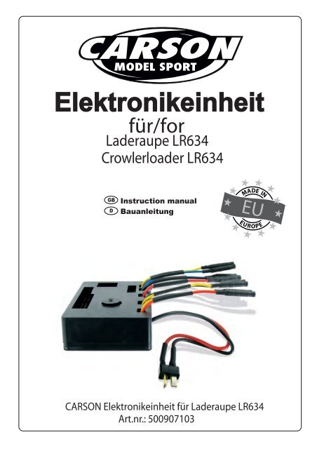
für/for<br />
<strong>Laderaupe</strong> <strong>LR634</strong><br />
Crowlerloader <strong>LR634</strong><br />
GB<br />
D<br />
Instruction manual<br />
Bauanleitung<br />
CARSON <strong>Elektronikeinheit</strong> für <strong>Laderaupe</strong> <strong>LR634</strong><br />
Art.nr.: 500907103
Sehr geeherter Kunde,<br />
wir beglückwünschen Sie zum Kauf Ihrer CARSON <strong>Elektronikeinheit</strong> für die CARSON<br />
Liebherr <strong>Laderaupe</strong> LR 634 (500 907111), welche nach dem heutigen Stand der Technik<br />
gefertigt wurde. Da wir stets um Weiterentwicklung und Verbesserung unserer Produkte<br />
bemüht sind, behalten wir uns eine Änderung in technischer Hinsicht und in Bezug auf<br />
Ausstattung, Materialien und Design jederzeit und ohne Ankündigung vor. Aus geringfügigen<br />
Abweichungen des Ihnen vorliegenden Produktes gegenüber Daten und Abbildungen<br />
dieser Anleitung können daher keinerlei Ansprüche abgeleitet werden. Diese Bedienungsanleitung<br />
ist Bestandteil des Produkts. Bei Nichtbeachtung der Bedienungsanleitung<br />
und der enthaltenen Sicherheitsanweisungen erlischt der Garantieanspruch.<br />
Bewahren Sie diese Anleitung zum Nachlesen auf und für die eventuelle Weitergabe des<br />
Modells an Dritte.<br />
Für dieses Produkt leistet CARSON eine Garantie von 24 Monaten betreffend Fehler bei<br />
der Herstellung in Bezug auf Material und Fertigung bei normalem Gebrauch ab dem<br />
Kauf beim autorisierten Fachhändler.<br />
Im Falle eines Defekts während der Garantiezeit bringen Sie das Modell zusammen mit<br />
dem Kaufbeleg zu<br />
Ihrem Fachhändler.<br />
CARSON wird nach eigener Entscheidung, falls nicht anders im Gesetz vorgesehen:<br />
• den Defekt durch Reparatur kostenlos in Bezug auf Material undArbeit beheben;<br />
• das Produkt durch ein gleichartiges oder im Aufbau ähnliches ersetzen; oder<br />
•den Kaufpreis erstatten.<br />
Alle ersetzten Teile und Produkte, für die Ersatz geleistet wird, werden zum Eigentum von<br />
CARSON. Im Rahmen der Garantieleistungen dürfen neue oder wiederaufbereitete Teile<br />
verwendet werden. Auf reparierte oder ersetzte Teile gilt eine Garantie für die Restlaufzeit<br />
der ursprünglichen Garantiefrist. Nach Ablauf der Garantiefrist vorgenommene Reparaturen<br />
oder gelieferte Ersatzteile werden in Rechnung gestellt.<br />
Von der Garantie ausgeschlossen sind:<br />
• Beschädigung oder Ausfall durch Nichtbeachten der Sicherheitsanweisungen oder der<br />
Bedienungsanleitung, höhere Gewalt, Unfall, fehlerhafte oder außergewöhnliche Beanspruchung,<br />
fehlerhafte Handhabung, eigenmächtige Veränderungen, Blitzschlag oder<br />
anderer Einfluss von Hochspannung oder Strom.<br />
• Schäden, die durch den Verlust der Kontrolle über Ihr Fahrzeug entstehen.<br />
• Reparaturen, die nicht durch einen autorisierten CARSON Service durchgeführt wurden<br />
• Verschleißteile wie etwa Sicherungen und Batterien<br />
• rein optische Beeinträchtigungen<br />
• Transport-, Versand- oder Versicherungskosten<br />
• Kosten für die Entsorgung des Produkts sowie Einrichten und vom Service vorgenommene<br />
Einstell- und Wiedereinrichtungsarbeiten. Durch diese Garantie erhalten Sie spezielle<br />
Rechte, darüber hinaus ist auch eine von Land zu Land verschiedene Geltendmachung<br />
anderer Ansprüche denkbar.
Lieferumfang:<br />
ENTSORGUNG:<br />
Bedeutung des Symbols auf dem Produkt, der Verpackung oder der<br />
Gebrauchsanleitung: Elektrogeräte sind Wertstoffe und gehören am<br />
Ende der Laufzeit nicht in den Hausmüll. Helfen Sie uns beim Umweltschutz<br />
und Resourcenschonung und geben Sie dieses Gerät bei den<br />
entsprechenden Rücknahmestellen ab. Fragen dazu beantwortet<br />
Ihnen die für die Abfallbeseitigung zuständige Organisation oder Ihr<br />
Fachhändler.<br />
o <strong>Elektronikeinheit</strong> (5 Fahrtregler • Rückfahrpiepser • Beleuchtung)<br />
o Kabelsatz Motoren (2x Fahrmotor)<br />
o Endlagenschalter Platine für Kippspindelantrieb<br />
o Endlagenschalter Platine für Hubspindelantrieb<br />
o LED Beleuchtungssatz (4x vorn • 2x hinten)<br />
o Bedienungsanleitung<br />
Vorbereitung der Getriebemotoren :<br />
Änderungen und Irrtümer vorbehalten.<br />
Alle Anschlusskabel der Getriebemotoren sind mit 2mm Goldkontakt-Steckern versehen,<br />
somit kann im Falle einer Verpolung die Drehrichtung des Motors geändert werden.<br />
Vor dem Einbau der Getriebemotoren müssen die Anschlusskabel wie folgt angelötet<br />
werden.<br />
- Motorkabel für Fahr-Getriebemotoren (2 Satz) (N° 500 907106) Kabel Farbcode<br />
o (1) Fahrmotor rechts / Kette rechts -> blau (-) / gelb (+)<br />
o (2) Fahrmotor links / Kette links -> gelb (-) / rot (+)<br />
- Motorkabel für Hubspindel-Getriebemotor (1 Satz) (N° 500 907066)<br />
- Wurden bereits an den Endlagenschalter Platine angelötet<br />
o (3) Motor für Spindelantrieb Heben-Senken -> schwarz (-) / blau (+)<br />
- Motorkabel für Kippspindel-Getriebemotor (1 Satz) (N° 500 907108)<br />
- Wurden bereits an der Endlagenschalter Platine angelötet<br />
o (4) Motor für Spindelantrieb Schaufel -> schwarz (-) / gelb (+)<br />
- Motorkabel für Heckaufreißer-Getriebemotor (1 Satz) (N° 500 907108)<br />
o (5) Motor für Spindelantrieb Heckaufreißer -> schwarz (-) / rot (+)<br />
Die Anschlusskabel sind angelötet und die Getriebemotoren<br />
sind nun bereit für den Einbau in das Modell. Bitte beachten<br />
Sie hierzu die weiteren Einbauschritte in der Aufbauanleitung<br />
des Modells.
Installation/Einbau der <strong>Elektronikeinheit</strong>:<br />
o Erklärung der <strong>Elektronikeinheit</strong><br />
- (1) Fahrtregler Fahrmotor Kette rechts<br />
- (2) Fahrtregler Fahrmotor Kette links<br />
- (3) Fahrtregler Hub-Spindelmotor / Endlagenschalter-Platine Hubspindel<br />
- (4) Fahrtregler Kipp-Spindelmotor / Endlagenschalter-Platine Kippspindel<br />
- (5) Fahrtregler Heckaufreißer-Spindelmotor<br />
- (6) T-Stecker Anschluss Fahrakku 7,2 V (6 NiMH) oder 7,4 V (2S Li-Po)<br />
(Immer auf die richtige Polarität achten!)<br />
- (7) LED-Anzeige (LED rot / LED gelb / LED grün)<br />
- (8) Taster – 1 Senderabgleich / Nullabgleich<br />
- (9) Taster – 2 Speichertaster für Senderabgleich/Nullabgleich<br />
- (10) Drehpotentiometer – Kettentrimmer (Kette links/rechts +/- 10%)<br />
- (11) Rückfahrpiepser<br />
- (12) nicht belegt<br />
- (13) Anschluss LED-Beleuchtung 2 – 4<br />
- (14) Empfänger-Anschluss Kanal 1 – 6<br />
(Polarität des Servoanschluß (von außen nach innen / Minus/Plus/Impuls))
Inbetriebnahme der <strong>Elektronikeinheit</strong> :<br />
(Benötigte Fernsteuerungsalage ab 6 Kanal z.B.: <strong>Carson</strong> Reflex)<br />
Stecken Sie die beiliegenden Servo-Anschlusskabel (JR) auf der <strong>Elektronikeinheit</strong> (siehe<br />
Abb. Nr. 14) von Kanal 1 bis Kanal 6 und verbinden diese mit Ihrem Empfänger in gleicher<br />
Reihenfolge (K1-K6).<br />
Nullabgleich/Neutraleinstellung von Sender und <strong>Elektronikeinheit</strong>:<br />
o 1) Drücken Sie den Taster – 1 (siehe Abb. Nr. 8) für ca. 1 Sek. bis alle LEDs (Rot /<br />
Gelb / Grün) leuchten (Antriebe sind deaktiviert). Sie befinden sich jetzt im<br />
Einstellungsmenü „Nullabgleich/Neutraleinstellung“.<br />
o 2) Drücken Sie den Taster – 2 (siehe Abb. Nr. 9) für ca. 1 Sek. Alle LEDs (Rot /<br />
Gelb / Grün) leuchten kurz auf und erlöschen wieder.<br />
Die Grüne LED beginnt zu blinken d.h. die <strong>Elektronikeinheit</strong> ist bereit für den<br />
Abgleich. Fahren Sie nun mit den Knüppeln in alle Endpositionen („Richtung und<br />
Reihenfolge sind nicht ausschlaggebend“) an und achten Sie dabei auf die<br />
Gelbe LED, wenn diese nicht mehr aufleuchtet hat die Elektronik alle maximal<br />
Ausschläge übernommen. (Während dieser Einstellung blinkt die Grüne LED<br />
weiter).<br />
o 3) Zum Speichern des Nullabgleich/Neutraleinstellung von Sender und <strong>Elektronikeinheit</strong><br />
drücken Sie wiederholt den Taster – 2 (siehe Abb. Nr. 9) für ca. 0,5 Sek.<br />
(die rote LED leuchtet kurz auf und die grüne LED beginnt zu leuchten).<br />
-Funktionen des linken Kreuzknüppel:<br />
o Fahren (vorwärts / rückwärts)<br />
-Kreuzknüppel nach vorn / nach hinten<br />
o Lenken (links / rechts)<br />
-Kreuzknüppel nach links / nach rechts<br />
o Drehen auf der Stelle (max. 70% der Leistung)<br />
-Kreuzknüppel Anschlag links oder Anschlag rechts<br />
- Funktionen des rechten Kreuzknüppel:<br />
o Schaufel kippen (links / rechts)<br />
-Kreuzknüppel nach links - füllen / nach rechts - leeren<br />
o Hubgerüst Aufwärts / Abwärts<br />
-Kreuzknüppel nach hinten – Aufwärts / nach vorn – Abwärts<br />
Funktionen der Schalter (E/A/E) und Taster (E/A/E)-Kombinationen:<br />
Schalterstellung „oben“ + Taster nach oben:<br />
- Licht 1 (Arbeitsscheinwerfer vorn/außen) / Rechter Knüppel – normale Funktionen
Schalterstellung „oben“ + Taster nach unten:<br />
- Licht 2 (Arbeitsscheinwerfer vorn/innen) / Rechter Knüppel – normale Funktionen<br />
Schalterstellung „mittig“ + Taster nach unten:<br />
- Rückfahrpiepser ein / aus (Piepser aktiviert sich nach dem Akkuwechsel automatisch<br />
wieder) / rechter Knüppel – normale Funktionen<br />
Schalterstellung „mittig“ + Taster nach oben:<br />
- Frei<br />
Schalterstellung „unten“ + Taster nach oben:<br />
-Licht 3 ein / aus (Arbeitsscheinwerfer hinten) / rechter Knüppel Heben/Senken<br />
Hubgerüst ist deaktiviert – Heben/Senken Heckaufreißer ist aktiviert<br />
Einstellung des Geradeauslauf/Kettentrimmer:<br />
o Achtung! : Ein Potentiometer (kurz „Poti“) ist ein sehr empfindliches elektronisches<br />
Bauteil, das bei Unachtsamkeit und Gewalteinwirkung zerstört werden kann!<br />
(Garantieausschluss)<br />
o Poti-Stellung mittig: Beide Fahrmotoren/Ketten laufen mit 100%<br />
o Poti-Stellung max. links: Der Linke Fahrmotor läuft mit 90%, der rechte mit 100%<br />
o Poti-Stellung max. rechts: Der Rechte Fahrmotor läuft mit 90%, der linke mit 100%<br />
o Sollte jedoch die Linke oder Rechte Kette schneller „laufen“, das Poti in die jeweilige<br />
Richtung drehen z.B. Die linke Kette läuft schneller, dann bitte das Poti mit einem<br />
geeigneten Schraubendreher vorsichtig! nach links drehen, diese Kette wird langsamer.<br />
Der max. Wert ist 10% langsamer. Nach der Einstellung fahren Sie mit Ihrem<br />
Modell eine gerade Strecke von 2 – 3 m sollte sich ein abweichen ergeben, ggf.<br />
nochmals nachjustieren.<br />
Spannungsüberwachung für 7,4V (2S) Li-Po Fahrakku :<br />
Die Spannung des Fahrakkus wird bei jedem Anschluss an der <strong>Elektronikeinheit</strong><br />
überprüft, (Dauer der Prüfung ca. 2 Sek.). Sollte die Spannung des Fahrakkus im Betrieb<br />
auf 5,8 Volt (2,9 Volt pro Zelle) absinken, so wird eine optische (alle 6 Arbeitsscheinwerfer<br />
blinken) und eine akustische (Piepton) Warnung ausgegeben. Den Betrieb sofort einstellen,<br />
damit der 7,4 Volt (2S) Li-Po Fahrakku nicht beschädigt wird. Beträgt die Dauer der<br />
optischen und akustischen Warnung mehr als 2 Sek., Fahrakku laden oder durch einen<br />
geladenen ersetzen.<br />
Einbau der <strong>Elektronikeinheit</strong> in das Modell<br />
Montieren Sie die <strong>Elektronikeinheit</strong> auf der dafür vorgesehenen „Radiodeck“ und befestigen<br />
sie diese mit 2 streifen doppelseitigem Klebeband.
(VORSICHT! Kurzschlussgefahr, achten Sie immer darauf dass alle Stromführenden<br />
Verbindungen keine Beschädigungen der Isolation aufweisen.)<br />
Technische Daten:<br />
Eingangsspannung:<br />
- 7,2 – 8,4 Volt<br />
6 Zellen (Sub-C) NiMH oder Li-Po 2S<br />
Belastbarkeit der Fahrtregler:<br />
- Regler Hubspindel 10 A/Dauer im Teillastbetrieb<br />
- Regler Kippspindel 10 A/Dauer im Teillastbetrieb<br />
- Regler Fahrmotoren je 5 A/Dauer im Teillastbetrieb<br />
- Regler Heckaufreißer 5 A/Dauer im Teillastbetrieb<br />
Lichtanschluss:<br />
- Max. 1 A<br />
Stecksystem:<br />
- Fahrakku T-Stecker/T-Plug<br />
- Regler 2 mm Goldkontaktbuchsen<br />
- Motorenkabel-Satz 2 mm Goldkontakstecker<br />
Abmessungen (L x B x H) & Gewicht:<br />
- 85 mm x 53 mm x 21 mm<br />
- Gewicht 82 Gramm
Dear Customer,<br />
we congratulate you for buying this CARSON Electronic unit for CARSON LIEBHERR<br />
Track loader LR 634 (500 90711), which is designed using state of the art technology.<br />
According to our policy of steady development and improvement of our products we<br />
reserve the right to make changes in specifications concerning equipment, materials and<br />
design of this product at any time without notice. Specifications or designs of the actual<br />
product may vary from those shown in this manual or on the box. The manual forms part<br />
of this product. Should you ignore the operating and safety instructions, the warranty will<br />
be void. Keep this guide for future reference.<br />
Limited Warranty:<br />
This product is warranted by CARSON against manufacturing defects in materials and<br />
workmanship under normal use for 24 months from the date of purchase from authorized<br />
franchisees and dealers. In the event of a product defect during the warranty period,<br />
return the product along with your receipt as proof of purchase to any CARSON store.<br />
CARSON will, at its option, unless otherwise provided by law:<br />
• Correct the defect by repairing the product without charging for parts and labor<br />
• replace the product with one of the same or similar design; or<br />
• Refund the purchase price.<br />
All replaced parts and products, and products on which a refund is made, become the<br />
property of CARSON. New or reconditioned parts and products may be used in the<br />
performance of warranty services. Repaired or replaced parts and products are warranted<br />
for the remainder of the original warranty period. You will be charged for repair or<br />
replacement of the product made after the expiration of the warranty period.<br />
The Warranty does not cover:<br />
• damage or failure caused by or attributable to acts of God, abuse, accident, misuse,<br />
improper or abnormal usage, failure to follow instructions, improper installation or<br />
maintenance, alteration, lightning or other incidence of excess voltage or current;<br />
• Damage caused by losing control of your car;<br />
• Any repairs other than those provided by a CARSON Authorized Service Facility;<br />
• Consumables such as fuses or batteries;<br />
• Cosmetic damage;<br />
• Transportation, shipping or insurance costs; or<br />
• costs of product removal, installation, set-up service adjustment or reinstallation This<br />
warranty gives you specific legal rights, and you may also have other rights which<br />
may vary according to the country of purchase.
Content:<br />
DISPOSAL:<br />
Please note and understand the symbols on this product, packaging or<br />
instructions. Electronic components are valuable materials and at the<br />
end of their useful life should not be disposed with household waste!<br />
Help us to protect the environment and safeguard our resources by<br />
discarding this equipment at a dedicated recycling point. The authority<br />
responsible for waste disposal or your retailer will be able to answer<br />
any questions you may have in this aspect.<br />
Changes and errors excepted<br />
o Electronic Unit (5 Electronic Speed Controller • Reversing beeper • LED Lights)<br />
o Motor Cable Kit (2x drive motor • 1x tip spindle • 1x lift spindle • 1x rear ripper )<br />
o Position indicator switch PCB for tip spindle<br />
o Position indicator switch PCB for lift spindle<br />
o LED Light Kit (4x front LED • 2x rear LED)<br />
o Instruction manual<br />
Preparation of the gear box motors:<br />
All Connecting cables are provided with 2 mm gold plug connector (ESC provided 2<br />
mm gold socket connector). The motor direction of rotation can be changed in case of<br />
reverse polarity.<br />
Before installing the gear motors, please solder the connection cable as follows.<br />
- Cable for Drive gear box motor (2 Sets) (N° 500 907106) cabel color code!<br />
o (1) Drive motor right / right track -> blue (-) / yellow (+)<br />
o (2) Drive motor left / left track -> yellow (-) / red(+)<br />
- Cable for Lift spindle gear box motor (1 Set) (N° 500 907066)<br />
- Already soldered on Position indicator switch PCB<br />
o (3) Motor for lift spindle drive lift and lower -> black (-) / blue (+)<br />
- Motorkabel für Kippspindel-Getriebemotor (1 Satz) (N° 500 907108)<br />
- Already soldered on Position indicator switch PCB<br />
o (4) Motor for tip spindle drive shovel -> black (-) / yellow (+)<br />
- Cable for rear ripper gear box motor (1 Set) (N° 500 907108)<br />
o (5) Motor for rear ripper spindle drive -> black (-) / red (+)<br />
The connecting cables are soldered and the geared motors<br />
are now ready for installationin to the model. Please note the<br />
additional installation steps in the assembly instructions from<br />
the model.
Installation of the electronic unit:<br />
o Electronic Unit Explanation<br />
- (1) Speed controller drive motor right track<br />
- (2) Speed controller drive motor left track<br />
- (3) Speed controller lift spindle drive / Position indicator switch PCB<br />
- (4) Speed controller tip spindle drive / Position indicator switch PCB<br />
- (5) Speed controller rear ripper spindle drive<br />
- (6) T-Plug Connector for Racing Pack 7,2 V (6 NiMH) or 7,4 V (2S Li-Po)<br />
(Do not connect the battery cable (plus and minus) with reversed polarity!)<br />
- (7) LED Status Display (LED red / LED yellow / LED green)<br />
- (8) Push button – 1 Transmitter alignment / Zero alignment<br />
- (9) Push button – 2 Memory push button for transmitter alignment/Zero alignment<br />
- (10) Rotary potentiometer – Track trimmer (Track left/right +/- 10%)<br />
- (11) Reversing beeper<br />
- (12) not used<br />
- (13) LED Light connecting Pins 2 – 4<br />
- (14) Receiver connecting Pins Channel 1 – 6<br />
(Polarity (from the outside to inwards / minus / plus /signal))
Commissioning of the electronics unit<br />
(Required 6 Channel Radio control system for exampel <strong>Carson</strong> Reflex)<br />
Plug the supplied servo cable (JR) to the elctronics unit (see Fig.No.14) from channel 1 to<br />
channel 6 and connect to your receiver in the same order (Channel 1 – Channel 6).<br />
- Zero alignment/Neutral setting from transmitter and electronic unit<br />
o 1) Press the Push button – 1 (see Fig. No. 8) for approx. 1 Sec. and the LEDs (Red<br />
/ Yellow / Green) will light up all (all Drives are disabled). You are now in the<br />
Setting menu „Zero alignment/ neutral setting”.<br />
o 2) Press the Push button – 2 (see Fig. No. 9) for approx. 1 Sec. and the LEDs (Red<br />
/ Yellow / Green) light up briefly and go out again. The Green LED begins to<br />
flash and the electronic unit is ready for the adjustment. Continue with the sticks<br />
in all the final positions („Direction and order are not decisive“), and taking note<br />
of the yellow LED, if this does not illuminate the electronics take over all<br />
maximum of rashes. (While this adjustment continues to flash the green LED).<br />
o 3) To save the zero alignment / neutral setting of the transmitter and electronic unit<br />
press repeatedly the push button - 2 (see Fig. No. 9) for approx. 0.5 Sec. (The<br />
red LED lights up briefly and the green LED will light). The settings are now<br />
complete and saved.<br />
- Functions of the left cross stick:<br />
o Drive function (forward / backward)<br />
-Cross stick forward / backward<br />
o Steering (left / right)<br />
-Cross stick to the left / to the right<br />
o Turn on the spot (max. 70% of the power)<br />
-Cross stick to left stop /or/ right stop<br />
- Function of the right cross stick:<br />
o Tipping shovel (left / right)<br />
-Cross stick to the left - fill / to the right - dump<br />
o Lowered mast up or down<br />
-Cross stick backward – upwards / forward – downwards<br />
Functions of the switches (on/off/on) and push button (on/off/on)-combinations:<br />
Switch position "above" and push button up:<br />
- Light 1 on / off (Work lights, front / outside) / Right cross stick - normal functions
Switch position „above“ and push button down:<br />
- Light 2 on / off (Work lights, front / inside) / Right cross stick – normal functions<br />
Switch position „center“ and push button down:<br />
- Reversing beeper on / off (Beeper is activated automatically after the battery change<br />
again) / Right cross stick – normal functions<br />
Switch position „center“ and push button up:<br />
- Not used<br />
Switch position „down“ and push botton up:<br />
- Light 3 on / off (Work lights, rear) / Right cross stick lowered mast up or down is<br />
disabled – rear ripper up or down is enabled<br />
Setting the straight-line / track trimmer:<br />
o Attention! : A potentiometer ("poti") is a very sensitive electronic components that<br />
can be destroyed by carelessness and violence! (not covered by the Warranty)<br />
o Potentiometer in the middle position: Both drive motors / tracks run at 100%<br />
o Potentiometer in the max. left position: The left drive motor is running at 90%, and<br />
the right with 100%<br />
o Potentiometer in the max. right position: The right drive motor is running with 90%,<br />
and the left with 100%<br />
o However, if the left or right track "runs" faster, turn the poti in each direction for<br />
example: The left track runs faster, please use a fitting screwdriver to adjust, turn<br />
carefully! to the left, and this track is getting slower. The max. to slow each track is<br />
10%. After adjustment, take your model and drive a straight line from 2 - 3 m if the<br />
result is different, if it´s necessary to readjust again.<br />
Voltage monitoring for 7.4V (2S) Li-Po battery:<br />
The voltage of the drive battery is checked at every connecting to the electronics unit,<br />
(Duration of the test about approx. 2 sec). If the voltage of the drive battery at the operating<br />
is lower then5,8 volts (2,9 Volt each Cell), so an optical (all 6 Working lights are<br />
flashing) and an acoustical signal warning (beep tone) will be activated (Battery low<br />
voltage protection). Stop operation immediately so that the 7.4 volts (2S) Li-Po battery is<br />
getting not damaged. Where the duration of the optical and acoustic warning more than 2<br />
seconds, charge the drive battery or replace it with a charged one.<br />
Installation of the electronics unit into the model<br />
Mount the electronics unit on the provided "radio deck" and fix it with two strips of double<br />
sided tape (not included).
…After<br />
installation<br />
„Radio deck“<br />
Before installation….<br />
(CAUTION! Short circuit, always make sure that all current-carrying cable show no<br />
damage on the insulation.)<br />
Technical Specifications:<br />
Input Voltage:<br />
- 7,2 – 8,4 Volt<br />
6 Cells (Sub-C) NiMH or Li-Po 2S (2 Cells)<br />
Carrying capacity of the speed controllers:<br />
- Speed controller Lift spindle 10 Amps (Duration in partial load operation)<br />
- Speed controller Tip spindle 10 Amps (Duration in partial load operation)<br />
- Speed controller Drive motor je 5 Amps (Duration in partial load operation)<br />
- Speed controller Rear Ripper 5 A (Duration in partial load operation)<br />
Light connection:<br />
- Max. 1 Amp. continuous<br />
Connector system:<br />
- Drive battery T-Plug<br />
- Speed controller 2 mm Gold sockets<br />
- Motor cable -Set 2 mm Gold plugs<br />
Dimension (L x W x H) and Weight:<br />
- 85 mm x 53 mm x 21 mm<br />
- Weight 82 Gramm
1<br />
Entfernen der Schrauben.<br />
Remove the screws.<br />
LROP 3<br />
3x18 mm<br />
Screw<br />
Schraube<br />
2<br />
DC9 x2<br />
3x22 mm<br />
Screw<br />
Schraube<br />
DC11 x<br />
DC11 3x22mm<br />
Motorkabel<br />
motor cable<br />
rotes Kabel=plus Kabel für Motor<br />
schwarz Kabel =minus Kabel für Motor<br />
Achtung: Verpolung zerstört die Mikroschalter<br />
DC9 3x18mm<br />
LROP 3<br />
black cable = negative cable to motor<br />
red cable is for cable plus motor<br />
Caution: Reverse polarity destroys the micro-switch
3<br />
Die Schrauben von Kippzylinder- Abdeckung entfernen.<br />
Remove the screws from the tilt protection.<br />
LROP 3<br />
4<br />
BA1 2mm<br />
Motorkabel<br />
motro cable<br />
20<br />
2 mm<br />
BA1 x2<br />
Nut<br />
Mutter<br />
ca.20mm<br />
2x5 mm<br />
QA3 x1<br />
Screw<br />
Schraube<br />
Endlagenschalter<br />
Platine<br />
Position Indicator<br />
Switch PBC<br />
QA3 2x5mm<br />
rotes Kabel=plus Kabel für Motor<br />
schwarz Kabel =minus Kabel für Motor<br />
Verpolung zerstört die Mikroschalter<br />
LROP 3<br />
black cable = negative cable to engine<br />
red cable = for cable plus motor<br />
Reverse polarity destroys the micro-switch
5<br />
DA3 2x5mm<br />
2x8 mm<br />
Screw<br />
Schraube<br />
QA5 2x8mm<br />
QA5 x1<br />
2x5 mm<br />
Screw<br />
Schraube<br />
DA3 2x5mm<br />
DA3 x4<br />
Schritt1: Den Kippzylinderschutz aufsetzen, die Schraube DA3 leicht anziehen<br />
Schritt2: Die Schraube QA5 vorsichtig in das Langloch eindrehen.<br />
Schritt3: Danach die Schrauben DA3 festziehen.<br />
Step 1: Put back again the tilt protrction on the tipping cylinder and tighten the<br />
screws DA3 slightly<br />
Step 2: Please screw carefully screw QA5 into the treaded hole<br />
Step 3: tighten the screws DA3 firmly<br />
LROP 3