Gebrauchs- und Montageanleitung - Harvia
Gebrauchs- und Montageanleitung - Harvia
Gebrauchs- und Montageanleitung - Harvia

Sie wollen auch ein ePaper? Erhöhen Sie die Reichweite Ihrer Titel.
YUMPU macht aus Druck-PDFs automatisch weboptimierte ePaper, die Google liebt.
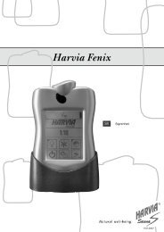
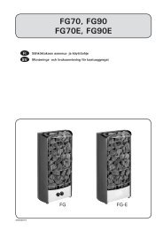
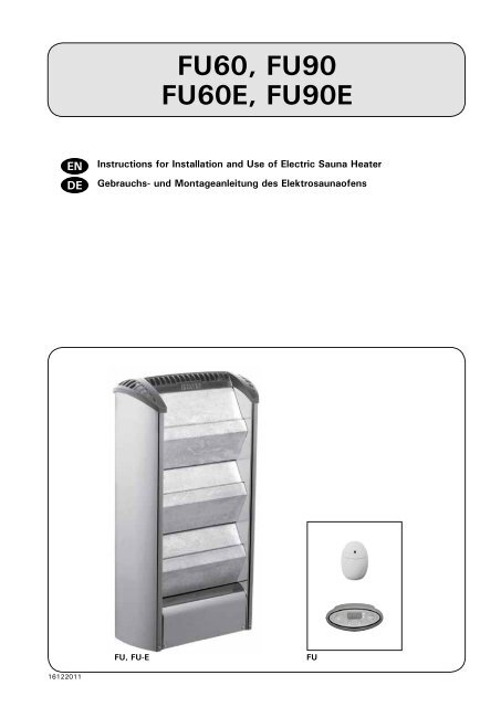
FU60, FU90<br />
FU60E, FU90E<br />
Instructions for Installation and Use of Electric Sauna Heater<br />
<strong>Gebrauchs</strong>- <strong>und</strong> <strong>Montageanleitung</strong> des Elektrosaunaofens<br />
FU, FU-E<br />
FU<br />
16122011
These instructions for installation and use are intended<br />
for the owner or the person in charge of the sauna, as<br />
well as for the electrician in charge of the electrical<br />
installation of the heater.<br />
After completing the installation, the person in charge<br />
of the installation should give these instructions to<br />
the owner of the sauna or to the person in charge<br />
of its operation.<br />
Congratulations on your choice!<br />
FUGA<br />
Purpose of the electric heater:<br />
The Fuga heater is for heating up family sauna rooms<br />
to bathing temperature. It is not to be used for any<br />
other purpose.<br />
The guarantee period for heaters and control<br />
equipment used in saunas by families is two (2)<br />
years. The guarantee period for heaters and control<br />
equipment used in saunas by building residents is<br />
one (1) year.<br />
Please read the user’s instructions carefully before<br />
using the heater.<br />
Diese Montage- <strong>und</strong> <strong>Gebrauchs</strong>anleitung richtet sich an<br />
den Besitzer der Sauna oder an die für die Pflege der Sauna<br />
verantwortliche Person, sowie an den für die Montage<br />
des Saunaofens zuständigen Elektromonteur.<br />
Wenn der Saunaofen montiert ist, wird diese Montage-<br />
<strong>und</strong> <strong>Gebrauchs</strong>anleitung an den Besitzer der<br />
Sauna oder die für die Pflege der Sauna verantwortliche<br />
Person übergeben.<br />
Wir beglückwünschen Sie zu Ihrer guten Saunaofenwahl!<br />
FUGA<br />
Verwendungszweck des Elektrosaunaofens:<br />
Der Fuga Saunaofen dient zum Erwärmen von Heimsaunakabinen<br />
auf die Saunatemperatur. Er sollte nicht<br />
für andere Zwecke verwendet werden.<br />
Die Garantiezeit für in Familiensaunen verwendete<br />
Saunaöfen <strong>und</strong> Steuergeräte beträgt zwei (2) Jahre.<br />
Die Garantiezeit für Saunaöfen <strong>und</strong> Steuergeräte, die<br />
in Gemainschaftsaunen in Privatgebäuden verwendet<br />
werden, beträgt ein (1) Jahr.<br />
Lesen Sie vor Inbetriebnahme die Anleitung für den<br />
Benutzer sorgfältig durch.<br />
CONTENTS<br />
1. INSTRUCTIONS FOR USE...............................................3<br />
1.1. Installation of the Sauna Stones..............................3<br />
1.2. Heating of the Sauna.............................................3<br />
1.3. Heater’s Control Units ..........................................4<br />
1.3.1. Heaters with Control Panel (FU60, FU90).........4<br />
1.3.2. Heaters with Separate Control Units (FU60E,<br />
FU90E)..................................................................5<br />
1.4. Throwing Water on Heated Stones..........................5<br />
1.4.1. Sauna Water................................................5<br />
1.4.2. Temperature and Humidity of the Sauna Room .7<br />
1.5. Instructions for Bathing .........................................8<br />
1.6. Warnings.............................................................8<br />
1.7. Troubleshooting....................................................8<br />
2. THE SAUNA ROOM....................................................... 9<br />
2.1. Insulation and Wall Materials of the Sauna Room......9<br />
2.1.1. Blackening of the Sauna Walls...................... 10<br />
2.2. Sauna Room Floor............................................... 10<br />
2.3. Heater Output..................................................... 10<br />
2.4. Ventilation of the Sauna Room.............................. 10<br />
2.5. Hygienic Conditions of the Sauna Room................. 11<br />
3. INSTRUCTIONS FOR INSTALLATION............................. 12<br />
3.1. Prior to Installation.............................................. 12<br />
3.2. Fastening the Heater on a Wall............................. 13<br />
3.3. Safety Railing..................................................... 13<br />
3.4. Electrical Connections.......................................... 13<br />
3.4.1. Installing the Temperature Sensor................. 14<br />
3.4.2. Resetting the Overheat Protector.................. 16<br />
3.4.3. Installation of the FU Heater Control Panel..... 16<br />
3.5. Electric Heater Insulation Resistance...................... 17<br />
4. SPARE PARTS............................................................ 17<br />
INHALT<br />
1. BedienungsANLEITUNG...............................................3<br />
1.1. Aufschichten der Saunaofensteine...........................3<br />
1.2. Erhitzen der Saunakabine.......................................3<br />
1.3. Steuerung des Saunaofens.....................................4<br />
1.3.1. Öfen mit Bedienfeld (FU60, FU90)..................4<br />
1.3.2. Öfen mit separatem Steuergerät (FU60E, FU90E)<br />
5<br />
1.4. Aufguss...............................................................5<br />
1.4.1. Aufgußwasser..............................................5<br />
1.4.2. Temperatur <strong>und</strong> Feuchtigkeit in der Saunakabine.<br />
7<br />
1.5. Anleitungen zum Saunen........................................8<br />
1.6. Warnungen...........................................................8<br />
1.7. Störungen............................................................8<br />
2. SAUNAKABINE............................................................. 9<br />
2.1. Isolation der Saunakabine <strong>und</strong> Wandmaterialien........9<br />
2.1.1. Verfärbung der Saunawände........................ 10<br />
2.2. Fußboden der Saunakabine................................... 10<br />
2.3. Leistung des Saunaofens...................................... 10<br />
2.4. Ventilation in der Saunakabine.............................. 10<br />
2.5. Hygiene in der Saunakabine.................................. 11<br />
3. MontageANLEITUNG................................................ 12<br />
3.1. Vor der Montage................................................. 12<br />
3.2. Befestigung des Saunaofens an der Wand............... 13<br />
3.3. Schutzgeländer................................................... 13<br />
3.4. Elektroanschlüße................................................. 13<br />
3.4.1. Montage des Temperaturfühlers.................... 14<br />
3.4.2. Zurückstellen der Überhitzungsschutzes......... 16<br />
3.4.3. Montage des Bedienfeldes des FU-Saunaofens.16<br />
3.5. Isolationswiderstand des Elektrosaunaofens............ 17<br />
4. ERSATZTEILE............................................................. 17
EN<br />
DE<br />
1. INSTRUCTIONS FOR USE 1. BedienungsANLEITUNG<br />
1.1. Installation of the Sauna Stones<br />
Only stones supplied by the heater manufacturer<br />
should be used in the FU/FU-E heater. The stones<br />
should be washed clean of stone dust prior to<br />
installation in the heater. The stones must be placed<br />
in the heater as shown in figure 1. When placing the<br />
stones in the heater, pay attention to the texture<br />
of the stones: the smooth surfaces must be placed<br />
outwards on the visible side. Prior to using the heater,<br />
ensure that the stones are firmly in place.<br />
Heater stones wear and disintegrate in use, and<br />
their characteristics deteriorate over time. Worn<br />
stones must be replaced, and the heater must not be<br />
used if a stone is broken or missing. All broken stones<br />
must be replaced immediately with new ones.<br />
The guarantee does not cover any faults caused by<br />
the use of stones not recommended by the plant.<br />
No such objects or devices should be placed inside<br />
the heater stone space or near the heater that could<br />
change the amount or direction of the air flowing<br />
through the heater, thus causing the resistance<br />
temperature to rise too high, which may set the wall<br />
surfaces on fire!<br />
1.2. Heating of the Sauna<br />
When the heater is switched on for the first time,<br />
both the heater and the stones emit smell. To remove<br />
the smell, the sauna room needs to be efficiently<br />
ventilated.<br />
The purpose of the heater is to raise the temperature<br />
of the sauna room and the sauna stones to the required<br />
bathing temperature. If the heater output is suitable<br />
for the sauna room, it will take about an hour for a<br />
properly insulated sauna to reach that temperature.<br />
1.1. Aufschichten der Saunaofensteine<br />
Nur vom Ofenhersteller bereitgestellte Steine sollten<br />
für den FU/FU-E-Ofen verwendet werden. Vor ihrem<br />
Aufschichten im Ofen sollten die Steine gewaschen<br />
werden, um Steinstaub zu entfernen. Die Steine<br />
müssen wie in Abbildung 1 gezeigt in den Ofen<br />
eingelegt werden. Beachten Sie dabei die Oberflächenstruktur<br />
der Steine: Die glatte Oberfläche muss<br />
nach außen, zur sichtbaren Seite weisen. Stellen Sie<br />
vor Inbetriebnahme des Ofens sicher, dass sich die<br />
Steine in einer stabilen Position befinden.<br />
Ofensteine nutzen sich ab <strong>und</strong> zerfallen bei häufigem<br />
Gebrauch, weshalb ihre Wirkung im Laufe<br />
der Zeit nachlässt. Abgenutzte Steine müssen ausgetauscht<br />
werden. Der Ofen darf nicht in Betrieb<br />
genommen werden, wenn ein Stein gebrochen ist<br />
oder fehlt. Alle gebrochenen Steine müssen sofort<br />
durch neue ersetzt werden.<br />
Die Garantie kommt nicht für Schäden auf, die<br />
durch Verwendung anderer als vom Ofenhersteller<br />
empfohlener Saunaofensteine entstehen.<br />
In der Steinkammer oder in der Nähe des Saunaofens<br />
dürfen sich keine Gegenstände oder Geräte befinden,<br />
die die Menge oder die Richtung des durch den<br />
Saunaofen führenden Luftstroms ändern, <strong>und</strong> somit<br />
eine Überhitzung der Widerstände sowie Brandgefahr<br />
der Wandflächen verursachen!<br />
1.2. Erhitzen der Saunakabine<br />
Beim ersten Erwärmen sondern sich von Saunaofen<br />
<strong>und</strong> Steinen Gerüche ab. Um diese zu entfernen, muß<br />
die Saunakabine gründlich gelüftet werden.<br />
Die Funktion des Saunaofens ist es, die Saunakabine<br />
<strong>und</strong> die Ofensteine auf die Aufgußtemperatur zu<br />
bringen. Wenn die Leistung des Saunaofens an die<br />
Größe der Saunakabine angepaßt ist, erwärmt sich<br />
eine gut wärmeisolierte Sauna auf Aufgußtemperatur<br />
in etwa einer St<strong>und</strong>e. Siehe Kapitel 2.1. ”Isolation der<br />
Sauna stones can be<br />
installed into the heater<br />
on either side.<br />
Die Saunasteine können<br />
von beiden Seiten in den<br />
Ofen eingelegt werden.<br />
A halogen bulb. Detach by pulling. Max. 20 W, 12 V, GU4<br />
Eine Halogenlampe. Kann durch Ziehen abgenommen werden. Max. 20 W, 12 V, GU4<br />
Figure 1. Changing a bulb of the heater light and installation of sauna stones<br />
Abbildung 1. Auswechseln der Glühbirne der Ofenlampe <strong>und</strong> Aufschichten der Saunasteine<br />
3
EN<br />
DE<br />
See item 2.1., ”Insulation and Wall Materials of the<br />
Sauna Room”. A suitable temperature for the sauna<br />
room is about +65 °C – +80 °C.<br />
The sauna stones normally reach the required<br />
bathing temperature at the same time as the sauna<br />
room. If the heater capacity is too big, the air in the<br />
sauna will heat very quickly, whereas the temperature<br />
of the stones may remain insufficient; consequently,<br />
the water thrown on the stones will run through. On<br />
the other hand, if the heater capacity is too low for<br />
the sauna room, the room will heat slowly and, by<br />
throwing water on the stones, the bather may try<br />
to raise the temperature of the sauna. However, the<br />
water will only cool down the stones quickly, and<br />
after a while the sauna will not be warm enough and<br />
the heater will not be able to provide enough heat.<br />
In order to make bathing enjoyable, the heater<br />
capacity should be carefully chosen to suit the size of<br />
the sauna room. See item 2.3. ”Heater Output”.<br />
1.3. Heater’s Control Units<br />
Heater models FU60 and FU90 are equipped with<br />
a separate control panel and an internal electronic<br />
power regulation unit, which is controlled by a<br />
computer and a separate temperature sensor.<br />
The FU60E and FU90E heaters must be equipped<br />
with a separate control unit which must be installed<br />
in a dry area outside of the sauna room.<br />
Before switching the heater on always check that<br />
there isn’t anything on top of the heater or inside the<br />
given safety distance. See item 1.6. “Warnings”.<br />
1.3.1. Heaters with Control Panel (FU60, FU90)<br />
Anyone using the heater can program the sauna’s<br />
temperature and the operating time according to<br />
preference from the heater’s control panel (see<br />
figure 2). Furthermore, by pressing a button on the<br />
panel the heater can be programmed to come on at<br />
the desired pre-setting time. The heater’s factory<br />
settings are as follows:<br />
• temperature about +65 ºC<br />
• on-time 4 hours<br />
• pre-setting time 0 hours<br />
The settings menu structure and changing the<br />
settings is shown in figures 3a and 3b. The programmed<br />
temperature value and all values of additional settings<br />
are stored in memory and will also apply when the<br />
device is switched on next time.<br />
Saunakabine <strong>und</strong> Wandmaterialien”. Die passende<br />
Temperatur in der Saunakabine beträgt etwa +65 °C<br />
bis +80 °C.<br />
Die Saunaofensteine erwärmen sich auf Aufgußtemperatur<br />
gewöhnlich in derselben Zeit wie die<br />
Saunakabine. Ein zu leistungsstarker Saunaofen<br />
erwärmt die Saunaluft schnell, aber die Steine bleiben<br />
untererhitzt <strong>und</strong> lassen so das Aufgußwasser<br />
durchfließen. Wenn andererseits die Saunaofenleistung<br />
in Bezug auf die Größe der Saunakabine gering<br />
ist, erwärmt sich die Saunakabine langsam <strong>und</strong> der<br />
Saunabader wird versuchen, die Saunatemperatur<br />
durch einen Aufguß (durch Gießen von Wasser auf<br />
den Saunaofen) zu erhöhen. Das Aufgußwasser kühlt<br />
aber nur die Saunaofensteine schnell ab <strong>und</strong> nach<br />
einer Weile reicht die Temperatur in der Sauna nicht<br />
mehr für einen Aufguß aus.<br />
Damit Sie beim Saunen die Aufgüsse genießen<br />
können, sollten Sie die Leistung des Saunaofens in<br />
Bezug auf die Saunakabine anhand der Broschüreninformationen<br />
sorgfältig auswählen. Siehe Kapitel<br />
2.3. ”Leistung des Saunaofens”.<br />
1.3. Steuerung des Saunaofens<br />
Die Saunaofenmodelle FU60 <strong>und</strong> FU90 sind mit einem<br />
eigenen Bedienfeld <strong>und</strong> einer internen elektronischen<br />
stromregulierenden Einheit ausgestattet, die durch<br />
einen Computer <strong>und</strong> einen separaten Thermostat<br />
gesteuert wird.<br />
Die Typen FU60E <strong>und</strong> FU90E werden mit einem<br />
separaten Steuergerät bedient, das außerhalb der<br />
Saunakabine an einem trockenen Ort angebracht<br />
werden soll.<br />
Bevor Sie den Ofen anschalten, bitte überprüfen,<br />
dass keine Gegenstände auf dem Ofen oder in der<br />
unmittelbarer Nähe des Ofens liegen. Siehe Kapitel<br />
1.6. “Warnungen”.<br />
1.3.1. Öfen mit Bedienfeld (FU60, FU90)<br />
Über das Bedienfeld des Ofens können Saunatemperatur<br />
<strong>und</strong> Einschaltdauer von jedem Benutzer<br />
individuell nach Wunsch eingestellt werden (siehe<br />
Abb. 2). Der Ofen kann außerdem über eine Taste<br />
des Bedienfelds so programmiert werden, dass er<br />
sich zu einem bestimmten Zeitpunkt einschaltet. Die<br />
Werkseinstellungen des Ofens lauten wie folgt:<br />
• Temperatur etwa +65 ºC<br />
• Einschaltdauer 4 St<strong>und</strong>en<br />
• Vorwahlzeit 0 St<strong>und</strong>en<br />
Die Struktur des Einstellungsmenüs <strong>und</strong> das Ändern<br />
der Werte wird in den Abbildungen 3a <strong>und</strong> 3b gezeigt.<br />
Der programmierte Temperaturwert <strong>und</strong> alle weiteren<br />
Einstellungswerte werden gespeichert <strong>und</strong> auch beim<br />
nächsten Einschalten des Geräts verwendet.<br />
1. Display<br />
2. Heater on/off switch<br />
3. Mode change<br />
4. Value decrease *)<br />
5. Value increase *)<br />
6. Temperature indicator light<br />
7. Timing operation indicator light<br />
2<br />
1 7 6 3<br />
1. Anzeige<br />
2. Ein/Aus-Schalter des Ofens<br />
3. Modus wechseln<br />
4. Wert verringern *)<br />
5. Wert erhöhen *)<br />
6. Temperaturkontrollleuchte<br />
7. Kontrollleuchte für die Zeitwahl<br />
*) Press and hold to make the value<br />
change faster.<br />
4<br />
5<br />
*) Gedrückt halten, damit die Werte<br />
sich schneller ändern.<br />
Figure 2. Control panel<br />
Abbildung 2. Bedienfeld<br />
4
EN<br />
DE<br />
Switching the Heater On and Off<br />
When the heater is connected to the power supply<br />
and the main switch at the bottom of the front<br />
part of the heater (see figure 9) is switched on, the<br />
heater is in standby mode (I/0 button’s backgro<strong>und</strong><br />
light glows).<br />
Start the heater by pressing the I/O<br />
button on the control panel.<br />
The heater makes a so<strong>und</strong> signifying the safety<br />
switch has come on. When the heater starts,<br />
the indicator light 6 flashes and the display will<br />
show the set temperature. After five seconds,<br />
the temperature in the sauna room appears in<br />
the screen.<br />
When the desired temperature has been<br />
reached in the sauna room, the heating elements<br />
are automatically turned off. To maintain the desired<br />
temperature, the power regulation unit will<br />
automatically turn the heating elements on and<br />
off in periods. The last decimal point in the display<br />
glows when the heating elements are on.<br />
The heater will turn off when the I/O button<br />
is pressed, the on-time runs out or an error occurs.<br />
1.3.2. Heaters with Separate Control Units<br />
(FU60E, FU90E)<br />
The FU-E heaters are controlled from a separate<br />
control unit. See the instructions for use of the<br />
selected control unit model.<br />
1.4. Throwing Water on Heated Stones<br />
The air in the sauna room becomes dry when warmed<br />
up. Therefore, it is necessary to throw water on the<br />
heated stones to reach a suitable level of humidity<br />
in the sauna.<br />
The humidity of the air in the sauna room is<br />
controlled by the amount of water thrown on the<br />
stones. A correct level of humidity makes the bather’s<br />
skin sweat and makes breathing easy. By throwing<br />
water on the stones with a small ladle, the bather<br />
should feel the effect of air humidity on his skin.<br />
Both too high a temperature and air humidity will<br />
give an unpleasant feeling.<br />
Staying in the hot sauna for long periods of time<br />
makes the body temperature rise, which may be<br />
dangerous.<br />
The maximum volume of the ladle is 0,2 litres.<br />
The amount of water thrown on the stones at a time<br />
should not exceed 0,2 litre, because if an excessive<br />
amount of water is poured on the stones, only part<br />
of it will evaporate and the rest may splash as boiling<br />
hot water on the bathers.<br />
Never throw water on the stones when there are<br />
people near the heater, because hot steam may<br />
burn their skin.<br />
1.4.1. Sauna Water<br />
The water to be thrown on the heated stones should<br />
meet the requirements of clean household water.<br />
The factors essentially affecting the quality of water<br />
include the following:<br />
• humus content (colour, taste, precipitates);<br />
Ein- <strong>und</strong> Ausschalten des Saunaofens<br />
Wenn der Ofen an die Stromquelle angeschlossen<br />
ist <strong>und</strong> der Hauptschalter unten an der Vorderseite<br />
des Ofens (siehe Abb. 9) eingeschaltet ist, befindet<br />
sich der Ofen im Standby-Modus (Kontrollleuchte<br />
des Schalters I/0 leuchtet).<br />
Drücken Sie auf dem Bedienfeld die<br />
I/O-Taste, um den Ofen einzuschalten.<br />
Es wird ein Geräusch, wie “klick” zu hören sein,<br />
um anzuzeigen, dass der Sicherheitsschalter aktiviert<br />
ist. Sobald der Ofen eingeschaltet ist, blinkt<br />
das Signallämpchen 6 <strong>und</strong> im Display erscheint<br />
die eingestellte Temperatur. Nach fünf Sek<strong>und</strong>en<br />
zeigt das Display die in der Saunakabine herrschende<br />
Temperatur.<br />
Sobald die gewünschte Temperatur in der<br />
Saunakabine erreicht wurde, werden die Heizelemente<br />
automatisch ausgeschaltet. Um die<br />
gewünschte Temperatur beizubehalten, schaltet<br />
das Steuergerät die Heizelemente in regelmäßigen<br />
Zeitabständen ein <strong>und</strong> aus. Der letzte Dezimalpunkt<br />
im Display leuchtet, wenn die Heizelemente<br />
eingeschaltet sind.<br />
Der Ofen wird ausgeschaltet, wenn die I/O-Taste<br />
gedrückt wird, die eingestellte Einschaltzeit<br />
abläuft oder ein Fehler auftritt.<br />
1.3.2. Öfen mit separatem Steuergerät (FU60E,<br />
FU90E)<br />
Die Öfen FU-E werden mit einem separaten Steuergerät<br />
bedient. Beachten Sie die mitgelieferte Bedienungsanleitung<br />
der Steuerung.<br />
1.4. Aufguss<br />
Die Saunaluft trocknet bei Erwärmung aus, daher<br />
sollte zur Erlangung einer angenehmen Luftfeuchtigkeit<br />
auf die heißen Steine des Saunaofens Wasser<br />
gegossen werden.<br />
Mit der Wassermenge wird die für angenehm<br />
empf<strong>und</strong>ene Aufgußfeuchtigkeit reguliert. Wenn die<br />
Luftfeuchtigkeit passend ist, schwitzt die Haut des<br />
Badenden <strong>und</strong> das Atmen in der Sauna fällt leicht. Es<br />
empfiehlt sich, zunächst nur kleine Mengen Wasser<br />
auf die Steine zu gießen, damit die Wirkung der<br />
Feuchtigkeit auf die Haut erprobt werden kann. Zu<br />
hohe Temperaturen <strong>und</strong> Feuchtigkeitsprozente fühlen<br />
sich unangenehm an.<br />
Ein langer Aufenthalt in einer heißen Sauna führt<br />
zum Ansteigen der Körpertemperatur, was gefährlich<br />
sein kann.<br />
Die Kapazität der Saunakelle sollte höchstens<br />
0,2 l betragen. Auf die Steine sollten keine größeren<br />
Wassermengen auf einmal gegossen werden, da beim<br />
Verdampfen sonst kochend heißes Wasser auf die<br />
Badenden spritzen könnte.<br />
Achten Sie auch darauf, daß Sie kein Wasser auf<br />
die Steine gießen, wenn sich jemand in deren Nähe<br />
befindet. Der heiße Dampf könnte Brandw<strong>und</strong>en<br />
verursachen.<br />
1.4.1. Aufgußwasser<br />
Als Aufgußwasser sollte nur Wasser verwendet werden,<br />
das die Qualitätsvorschriften für Haushaltswasser erfüllt.<br />
Wichtige Faktoren für die Wasserqualität sind:<br />
• Humusgehalt (Farbe, Geschmack,<br />
Ablagerungen); Empfehlung unter 12 mg/l.<br />
5
EN<br />
DE<br />
recommended content less than 12 mg/litre.<br />
• iron content (colour, smell, taste, precipitates);<br />
recommended content less than 0,2 mg/litre.<br />
• hardness – the most important substances<br />
are manganese (Mn) and calcium (Ca);<br />
recommended content of manganese 0,05 mg/<br />
litre, calcium less than 100 mg/litre.<br />
Calcareous water leaves a white, sticky layer on the<br />
stones and metal surfaces of the heater. Calcification<br />
of the stones deteriorates the heating properties.<br />
Ferrous water leaves a rusty layer on the surface<br />
of the heater and elements, and causes corrosion.<br />
The use of humous, chlorinated water and seawater<br />
• Eisengehalt (Farbe, Geruch, Geschmack,<br />
• Ablagerungen); Empfehlung unter 0,2 mg/l.<br />
• Härtegrad; die wichtigsten Stoffe sind Mangan<br />
(Mn) <strong>und</strong> Kalzium (Ca) oder Kalk; Empfehlung<br />
für Mangan unter 0,05 mg/l <strong>und</strong> für Kalzium<br />
unter 100 mg/l.<br />
Bei Verwendung kalkhaltigen Wassers verbleibt auf<br />
den Steinen <strong>und</strong> Metalloberflächen des Saunaofens<br />
eine helle, cremeartige Schicht. Die Verkalkung der<br />
Steine schwächt die Aufgußeigenschaften ab.<br />
Bei Verwendung eisenhaltigen Wassers verbleibt<br />
auf der Ofenoberfläche <strong>und</strong> den Widerständen eine<br />
rostige Schicht, die Korrosion verursacht.<br />
Basic settings/GRUNDEINSTELLUNGEN<br />
Basic mode (heater on)<br />
The display shows the sauna room<br />
temperature.<br />
Basis-Modus (Ofen ein)<br />
Die Anzeige zeigt die Temperatur in der<br />
Saunakabine an.<br />
Press the MENU button to open the<br />
settings menu.<br />
Sauna room temperature<br />
The display shows the sauna room temperature<br />
setting. Indicator light 6 blinks.<br />
• Change the setting to the desired<br />
temperature with the – and +<br />
buttons. The range is 40–110 ºC.<br />
Press the MENU button to access the<br />
next setting.<br />
Remaining on-time<br />
Press the + and – buttons to adjust the<br />
remaining on-time.<br />
Öffnen Sie das Einstellungsmenü, indem Sie die<br />
MENU-Taste drücken.<br />
Temperatur in der Saunakabine<br />
Das Display zeigt die Temperatureinstellung für<br />
die Saunakabine an. Die Kontrollleuchte 6 blinkt.<br />
• Ändern Sie die Einstellung mit den Tasten<br />
– <strong>und</strong> + auf die gewünschte Temperatur. Der<br />
Einstellbereich beträgt 40–110 °C.<br />
Gehen Sie zur nächsten Einstellung über, indem<br />
Sie die MENU-Taste drücken.<br />
Verbleibende Einschaltzeit<br />
Stellen Sie mit den Tasten – <strong>und</strong> + die<br />
verbleibende Einschaltzeit ein.<br />
Example: the heater will be on for 3 hours<br />
and 30 minutes.<br />
Beispiel: Der Saunaofen wird 3 St<strong>und</strong>en <strong>und</strong><br />
30 Minuten lang laufen.<br />
Pre-setting time (timed switch-on)<br />
• Press the + button until you<br />
overstep the maximum on-time.<br />
Indicator light 7 blinks.<br />
• Select the desired pre-setting time<br />
using the – and + buttons. The time<br />
may be pre-set at intervals of 10<br />
minutes up to 10 hours and one hour<br />
from 10 to 18 hours.<br />
Vorwahlzeit (zeitgesteuertes Einschalten)<br />
• Drücken Sie die Taste +, bis die maximale<br />
Einschaltzeit überschritten ist. Die<br />
Kontrollleuchte 7 blinkt.<br />
• Wählen Sie mit den Tasten – <strong>und</strong> + die<br />
gewünschte Vorwahlzeit aus. Die Zeit kann<br />
für bis zu 10 St<strong>und</strong>en in Schritten von 10<br />
Minuten <strong>und</strong> ab 10 bis zu 18 St<strong>und</strong>en in<br />
Schritten von einer St<strong>und</strong>e eingestellt werden.<br />
Example: the heater will start after 10 minutes.<br />
Press the MENU button to exit.<br />
Beispiel: Der Saunaofen wird in 10 Minuten eingeschaltet.<br />
Drücken Sie die MENU-Taste, um die<br />
Einstellungen zu beenden.<br />
Basic mode (pre-setting time running, heater off)<br />
The decrease of remaining pre-setting time is<br />
shown until zero appears, after which the heater<br />
is switched on.<br />
Figure 3a. Settings menu structure, basic settings<br />
Abbildung 3a. Struktur des Einstellungsmenüs, Gr<strong>und</strong>einstellungen<br />
Basis-Modus (Vorwahlzeit läuft, Ofen aus)<br />
Die sich verringernde Vorwahlzeit wird bis zum<br />
Stand von null angezeigt, <strong>und</strong> anschließend<br />
wird der Ofen eingeschaltet.<br />
6
EN<br />
DE<br />
Additional settings/WEITERE EINSTELLUNGEN<br />
Heater standby<br />
Standby des Ofens<br />
Switch the power off from the electric<br />
switch (see figure 9). Press and hold the<br />
MENU button, then switch the power on<br />
from the electric switch.<br />
Wait until the display shows the program<br />
version number.<br />
• Press + to change the maximum ontime<br />
setting<br />
• Press – to change the sensor reading<br />
adjustment setting<br />
Maximum on-time<br />
The maximum on-time can be changed<br />
with the – and + buttons. Adjustment<br />
range: family saunas 2–6 h, public<br />
saunas in apartment buildings 2–8 h.<br />
Example: the heater will be on for 4 hours<br />
from the start. (Remaining on-time can be<br />
changed, see figure 3a.)<br />
Unterbrechen Sie die Stromzufuhr zur Elektronik<br />
des Ofens (siehe Abbildung 9). Halten Sie die<br />
MENU-Taste gedrückt <strong>und</strong> schalten Sie die<br />
Stromzufuhr wieder ein.<br />
Warten Sie, bis im Display die Nummer der<br />
Programmversion erscheint.<br />
• Drücken Sie +, um die maximale<br />
Einschaltzeit zu verändern.<br />
• Drücken Sie –, um die Einstellung des<br />
Fühlerwerts zu verändern.<br />
Maximale Einschaltzeit<br />
Die maximale Einschaltzeit kann mit den Tasten<br />
– <strong>und</strong> + geändert werden. Einstellbereich:<br />
Familiensaunen 2–6 h, öffentliche Saunen in<br />
Apartmentgebäuden 2–8 h.<br />
Beispiel: Der Saunaofen wird von Beginn an 4<br />
St<strong>und</strong>en lang laufen. (Die verbleibende Einschaltzeit<br />
kann geändert werden, siehe Abb. 3a.)<br />
Sensor reading adjustment<br />
The reading can be corrected by -10<br />
units. The adjustment does not affect the<br />
measured temperature value directly, but<br />
changes the measuring curve.<br />
Press the MENU button. The heater<br />
switches to standby-mode.<br />
Einstellung des Fühlerwerts<br />
Die Messwerte können um -10 Einheiten<br />
korrigiert werden. Die Einstellung betrifft<br />
nicht den gemessenen Temperaturwert direkt,<br />
sondern ändert die Messkurve.<br />
Drücken Sie die MENU-Taste. Der Ofen schaltet<br />
in den Standby-Modus um.<br />
Figure 3b. Settings menu structure, additional settings<br />
Abbildung 3b. Struktur des Einstellungsmenüs, weitere Einstellungen<br />
is forbidden.<br />
Only special perfumes designed for sauna water<br />
may be used. Follow the instructions given on the<br />
package.<br />
1.4.2. Temperature and Humidity of the Sauna Room<br />
Both thermometers and hygrometers suitable for<br />
use in a sauna are available. As the effect of steam<br />
on people varies, it is impossible to give an exact,<br />
universally applicable bathing temperature or percentage<br />
of moisture. The bather’s own comfort is<br />
the best guide.<br />
The sauna room should be equipped with proper<br />
ventilation to guarantee that the air is rich in oxygen<br />
and easy to breathe. See item 2.4. ”Ventilation of<br />
the Sauna Room”.<br />
Bathing in a sauna is considered a refreshing experience<br />
and good for the health. Bathing cleans and<br />
warms your body, relaxes the muscles, soothes and<br />
alleviates oppression. As a quiet place, the sauna<br />
offers the opportunity to meditate.<br />
Die Verwendung von humus- <strong>und</strong> chlorhaltigem<br />
Wasser sowie von Meerwasser ist verboten.<br />
Im Aufgußwasser dürfen nur für diesen Zweck<br />
ausgewiesene Duftstoffe verwendet werden. Befolgen<br />
Sie die Anweisungen auf der Packung.<br />
1.4.2. Temperatur <strong>und</strong> Feuchtigkeit in der Saunakabine<br />
Zur Messung der Temperatur <strong>und</strong> Feuchtigkeit gibt<br />
es Meßgeräte, die für den Gebrauch in einer Sauna<br />
geeignet sind. Es ist allerdings unmöglich, allgemeingültig<br />
<strong>und</strong> genau die zum Saunen geeigneten<br />
Temperaturen oder Feuchtigkeitsprozente zu nennen,<br />
da jeder Mensch die Wirkung des Aufgusses in der<br />
Sauna anders empfindet. Das eigene Empfinden ist<br />
das beste Thermometer des Badenden!<br />
Eine sachgemäße Ventilation in der Sauna ist<br />
wichtig, denn die Saunaluft muß sauerstoffreich <strong>und</strong><br />
leicht zu atmen sein. Siehe Kapitel 2.4. ”Ventilation<br />
in der Saunakabine”.<br />
Menschen empfinden das Saunen als ges<strong>und</strong> <strong>und</strong><br />
erfrischend. Das Saunen säubert, erwärmt, entspannt,<br />
beruhigt, lindert psychische Bedrücktheit <strong>und</strong> bietetals<br />
ruhiger Ort die Möglichkeit zum Nachdenken.<br />
7
EN<br />
1.5. Instructions for Bathing<br />
• Begin by washing yourself; for example, by<br />
taking a shower.<br />
• Stay in the sauna for as long as you feel<br />
comfortable.<br />
• According to established sauna conventions,<br />
you must not disturb other bathers by speaking<br />
in a loud voice.<br />
• Do not force other bathers from the sauna by<br />
throwing excessive amounts of water on the<br />
stones.<br />
• Forget all your troubles and relax.<br />
• Cool your skin down as necessary.<br />
• If you are in good health, you can have a swim<br />
if a swimming place or pool is available.<br />
• Wash yourself properly after bathing. Have<br />
a drink of fresh water or a soft drink to bring<br />
your fluid balance back to normal.<br />
• Rest for a while and let your pulse go back to<br />
normal before dressing.<br />
1.6. Warnings<br />
• Sea air and a humid climate may corrode the<br />
metal surfaces of the heater.<br />
• Do not hang clothes to dry in the sauna, as this<br />
may cause a risk of fire. Excessive moisture<br />
content may also cause damage to the<br />
electrical equipment.<br />
• Keep away from the heater when it is hot. The<br />
stones and outer surface of the heater may<br />
burn your skin.<br />
• Do not throw too much water on the stones.<br />
The evaporating water is boiling hot.<br />
• Do not let young, handicapped or ill people<br />
bathe in the sauna on their own.<br />
• Consult your doctor about any health-related<br />
limitations to bathing.<br />
• Parents should keep children away from the<br />
hot heater.<br />
• Consult your child welfare clinic about taking<br />
little babies to the sauna.<br />
- age, temperature of the sauna, time spent in<br />
the warm sauna?<br />
• Be very careful when moving in the sauna, as<br />
the platform and floors may be slippery.<br />
• Never go to a hot sauna if you have taken<br />
alcohol, strong medicines or narcotics.<br />
1.7. Troubleshooting<br />
If the heater does not heat, check the following<br />
points:<br />
• the electricity has been switched on.<br />
• the control unit shows a higher figure than the<br />
temperature of the sauna.<br />
• the fuses (3 pcs) to the heater are in good<br />
condition.<br />
• the overheat protector has not gone off (see<br />
fig. 13).<br />
If an error occurs, the heater power will cut off and<br />
the control panel will show an error message ”E<br />
(number)”, which helps troubleshooting the cause<br />
for the error. Table 1.<br />
DE<br />
1.5. Anleitungen zum Saunen<br />
• Waschen Sie sich vor dem Saunen. Eine<br />
Dusche dürfte genügen.<br />
• Bleiben Sie dann in der Sauna, solange Sie es<br />
als angenehm empfinden.<br />
• Zu guten Saunamanieren gehört, daß Sie<br />
Rücksicht auf die anderen Badenden nehmen,<br />
indem Sie diese nicht mit unnötig lärmigem<br />
Benehmen stören.<br />
• Verjagen Sie die anderen auch nicht mit zu<br />
vielen Aufgüssen.<br />
• Vergessen Sie jeglichen Streß, <strong>und</strong> entspannen<br />
Sie sich.<br />
• Lassen Sie Ihre erhitzte Haut zwischendurch<br />
abkühlen.<br />
• Falls Sie ges<strong>und</strong> sind, <strong>und</strong> die Möglichkeit dazu<br />
besteht, gehen Sie auch schwimmen.<br />
• Waschen Sie sich nach dem Saunen. Nehmen<br />
Sie zur Rückgewinnung der verlorenen<br />
Flüssigkeit ein erfrischendes Getränk zu sich.<br />
• Ruhen Sie sich aus, bis Sie sich ausgeglichen<br />
fühlen <strong>und</strong> ziehen Sie sich an.<br />
1.6. Warnungen<br />
• Meer- <strong>und</strong> feuchtes Klima können die<br />
Metalloberflächen des Saunaofens rosten lassen.<br />
• Benutzen Sie die Sauna wegen der Brandgefahr<br />
nicht zum Kleider- oder Wäschetrocknen,<br />
außerdem können die Elektrogeräte durch die<br />
hohe Feuchtigkeit beschädigt werden.<br />
• Achtung vor dem heißen Saunaofen. Die Steine<br />
so wie das Gehäuse werden sehr heiß <strong>und</strong><br />
können die Haut verbrennen.<br />
• Auf die Steine darf nicht zuviel Wasser auf<br />
einmal gegossen werden, da das auf den<br />
heißen Steinen verdampfende Wasser die Haut<br />
verbrennen kann.<br />
• Kinder, Gehbehinderte, Kranke <strong>und</strong> Schwache<br />
dürfen in der Sauna nicht alleingelassen werden.<br />
• Ges<strong>und</strong>heitliche Einschränkungen bezogen auf das<br />
Saunen müssen mit dem Arzt besprochen werden.<br />
• Eltern dürfen ihre Kinder nicht in die Nähe des<br />
Saunaofens lassen.<br />
• Über das Saunen von Kleinkindern sollten Sie<br />
sich in der Mütterberatungsstelle beraten lassen.<br />
Alter, Saunatemperatur, Saunadauer?<br />
• Bewegen Sie sich in der Sauna mit besonderer<br />
Vorsicht, da die Bänke <strong>und</strong> der Fußboden glatt<br />
sein können.<br />
• Gehen Sie nicht in die Sauna, wenn Sie<br />
unter dem Einfluß von Narkotika (Alkohol,<br />
Medikamenten, Drogen usw.) stehen.<br />
1.7. Störungen<br />
Falls sich der Saunaofen nicht erwärmt, überprüfen<br />
Sie folgende Punkte:<br />
• Strom ist eingeschaltet.<br />
• Das Thermostat ist auf eine höhere als in der<br />
Sauna herrschende Temperatur eingestellt.<br />
• Die Sicherungen (3 St.) des Saunaofens sind heil.<br />
• Der Temperaturschutz ist nicht entriegelt<br />
worden (Siehe Abb. 13)<br />
Wenn eine Störung auftritt, wird der Ofen abgeschaltet,<br />
<strong>und</strong> auf dem Bedienfeld wird eine Fehlermeldung<br />
im Format “E (Nummer)” angezeigt, die Hilfe bei der<br />
Störungsbeseitigung bietet. Tabelle 1.<br />
8
EN<br />
DE<br />
Description/Beschreibung Remedy/Abhilfe<br />
ER1 Temperature sensor's measuring<br />
circuit broken.<br />
Check the red and yellow wires to the temperature sensor and their<br />
connections (see figure 10) for faulties.<br />
Messkreis des Temperaturfühlers<br />
unterbrochen.<br />
Prüfen Sie die roten <strong>und</strong> gelben Kabel zum Temperaturfühler <strong>und</strong> deren<br />
Verbindungen (siehe Abb. 10) auf Fehler.<br />
ER2 Temperature sensor's measuring<br />
circuit short-circuited.<br />
Check the red and yellow wires to the temperature sensor and their<br />
connections (see figure 10) for faulties.<br />
Kurzschluss im Messkreis des<br />
Temperaturfühlers.<br />
Prüfen Sie die roten <strong>und</strong> gelben Kabel zum Temperaturfühler <strong>und</strong> deren<br />
Verbindungen (siehe Abb. 10) auf Fehler.<br />
Table 1. Error messages. Note! All service operations must be done by professional maintenance personnel.<br />
Tabelle 1. Fehlermeldungen. Achtung! Alle Wartungsmaßnahmen müssen von qualifiziertem technischem Personal<br />
durchgeführt werden.<br />
2. THE SAUNA ROOM 2. SAUNAKABINE<br />
2.1. Insulation and Wall Materials of the<br />
Sauna Room<br />
In an electrically heated sauna, all the massive wall<br />
surfaces which store plenty of heat (such as bricks,<br />
glass blocks, plaster etc.), must be sufficiently<br />
insulated in order to keep the heater output at a<br />
reasonably low level.<br />
A wall and ceiling construction can be considered<br />
to have efficient thermal insulation if:<br />
• the thickness of carefully fitted insulating wool<br />
inside the house is 100 mm (minimum 50 mm)<br />
• the moisture protection consists of e.g.<br />
aluminium paper with tightly taped edges. The<br />
paper must be fitted so that the glossy side is<br />
towards the inside of the sauna<br />
• there is a 10 mm vent gap between the<br />
moisture protection and panel boards<br />
(recommendation)<br />
• the inside is covered by 12–16 mm thick<br />
panelling<br />
• there is a vent gap of a few millimetres at the<br />
top of the wall covering at the edge of the<br />
ceiling panelling<br />
When aiming at a reasonable heater output, it may<br />
be advisable to lower the ceiling of the sauna (normally<br />
2100–2300 mm, minimum height 1900 mm). As a<br />
result, the volume of the sauna is decreased, and a<br />
smaller heater output may be sufficient. The ceiling<br />
can be lowered so that the ceiling joists are fixed at<br />
a suitable height. The spaces between the joists are<br />
insulated (minimum insulation 100 mm) and surfaced<br />
as described above.<br />
Because heat goes upwards, a maximum distance<br />
of 1100–1200 mm is recommended between the<br />
bench and ceiling.<br />
NOTE! Consult fire-extinguishing authorities to find<br />
out which part of the fireproof wall may be insulated.<br />
Do not insulate air chimneys.<br />
NOTE! The protection of the walls or ceiling with<br />
heat protection, such as mineral board fitted directly<br />
on the wall or ceiling, may cause the temperature<br />
of the wall and ceiling materials to rise dangerously<br />
high.<br />
2.1. Isolation der Saunakabine <strong>und</strong><br />
Wandmaterialien<br />
In einer elektrisch beheizten Sauna müssen alle<br />
massiven Wandflächen, die viel Wärme speichern<br />
(Ziegel, Glasziegel, Mörtel o.ä.) ausreichend isoliert<br />
werden, um mit einer relativ geringen Leistung des<br />
Saunaofens auszukommen.<br />
Für gut isoliert kann man eine solche Sauna<br />
halten, die mit folgender Wand- <strong>und</strong> Deckenstruktur<br />
ausgestattet ist:<br />
• Die Dicke der sorgfältig gelegten Isolierwolle<br />
beträgt auch im Hausinneren 100 mm<br />
(mindestens 50 mm)<br />
• Als Feuchtigkeitssperre wird z.B.<br />
Aluminiumpapier verwendet, dessen Ränder<br />
sorgfältig dicht gefaltet werden <strong>und</strong> das so<br />
angebracht wird, daß die glänzende Seite zum<br />
Inneren der Sauna zeigt<br />
• Zwischen Feuchtigkeitssperre <strong>und</strong> Paneelen<br />
befindet sich (empfehlenswert) ein 10 mm<br />
großer Entlüftungsspalt<br />
• Als Innenbeschichtung werden leichtgewichtige<br />
Paneelbretter verwendet, die eine Dicke von<br />
etwa 12–16 mm haben<br />
• Über der Wandverkleidung an der Grenze<br />
zu den Deckenpaneelbrettern wird ein<br />
Entlüftungsspalt von einigen mm gelassen<br />
Um eine angemessene Saunaofenleistung zu erreichen,<br />
kann es erforderlich werden, die Saunadecke<br />
weiter nach unten abzusenken (norm. 2100–<br />
2300 mm, min. Saunahöhe 1900 mm), so daß der<br />
Rauminhalt der Sauna kleiner wird <strong>und</strong> eventuell<br />
eine geringere Saunaofenleistung gewählt werden<br />
kann. Die Absenkung der Decke wird durchgeführt,<br />
indem man das Gebälk auf passender Höhe anbringt.<br />
Die Balkenzwischenräume werden isoliert (Isolation<br />
mindestens 100 mm) <strong>und</strong> wird wie oben beschrieben<br />
von innen verkleidet.<br />
Da Wärme nach oben steigt, wird als Abstand<br />
zwischen Saunabank <strong>und</strong> Decke höchstens 1100–<br />
1200 mm empfohlen.<br />
ACHTUNG! Zusammen mit einem Brandschutzbeamten<br />
muß festgestellt werden, welche Teile der<br />
Brandmauer isoliert werden dürfen. Sich in Benutzung<br />
befindliche Abzüge dürfen nicht isoliert werden!<br />
ACHTUNG! Der Schutz von Wänden oder der Decke<br />
mit leichten Abdeckungen, z.B. Mineralplatten, die<br />
direkt an den Wand- oder Deckenflächen befestigt<br />
werden, kann einen gefährlichen Temperaturanstieg<br />
in den Wand- <strong>und</strong> Deckenmaterialien verursachen.<br />
9
EN<br />
DE<br />
2.1.1. Blackening of the Sauna Walls<br />
Wooden material in a sauna, such as panels, blackens<br />
with age. The blackening process is sped up by<br />
sunlight and the heat from the heater. If the wall<br />
surfaces have been processed with protective panel<br />
agents, the blackening of the surface of the wall<br />
above the heater can be seen quite quickly depending<br />
on the protective agent used. The blackening is<br />
due to the fact that the protective agents have less<br />
resistance to heat than unprocessed wood do. This<br />
has been proven in practical tests.<br />
The micronic mineral aggregate that crumbles<br />
from the stones on the heater may blacken the wall<br />
surface near the heater.<br />
When following the manufacturer’s approved<br />
guidelines in the installation of the sauna heater,<br />
the heater will not heat up enough to endanger the<br />
flammable material in the sauna room. The maximum<br />
temperature allowed in the wall and ceiling surfaces<br />
of the sauna room is +140 degrees Celsius.<br />
Sauna heaters equipped with CE signs meet all<br />
of the regulations for sauna installations. Proper<br />
authorities monitor that the regulations are being<br />
followed.<br />
2.2. Sauna Room Floor<br />
Due to a large variation in temperature, the sauna<br />
stones disintegrate in use.<br />
Small pieces of stone are washed down on the<br />
sauna room floor along with the water thrown on<br />
the stones. Hot pieces of stone may damage plastic<br />
floor coverings installed <strong>und</strong>erneath and near the<br />
heater.<br />
A light-coloured joint grout, used for a tiled floor,<br />
may absorb impurities from the stones and water<br />
(e.g iron content).<br />
To prevent aesthetic damage (due to the reasons<br />
presented above) only dark joint grouts and floor<br />
coverings made of rock materials should be used<br />
<strong>und</strong>erneath and near the heater.<br />
2.3. Heater Output<br />
When the walls and ceiling are covered with panels,<br />
and the insulation behind the panels is sufficient<br />
to prevent thermal flow into the wall materials,<br />
the heater output is defined according to the cubic<br />
volume of the sauna. See table 2.<br />
If the sauna has visible uninsulated wall surfaces,<br />
such as walls covered with brick, glass block, concrete<br />
or tile, each square metre of said wall surface causes<br />
the cubic volume of the sauna to increase by 1.2 m 3 .<br />
The heater output is then selected according to the<br />
values given in the table.<br />
Because log walls are heated slowly, the cubic<br />
volume of a log sauna should be multiplied by 1.5,<br />
and the heater output should then be selected on<br />
the basis of this information.<br />
2.4. Ventilation of the Sauna Room<br />
Sufficient ventilation is extremely important for<br />
the sauna. The air in the sauna room should be<br />
changed six times per hour. The air supply pipe<br />
should be located at a minimum height of 500 mm<br />
above the heater. The pipe diameter should be about<br />
10<br />
2.1.1. Verfärbung der Saunawände<br />
Die Holzmaterialien in der Sauna, wie z.B. die<br />
Holzverkleidungen, verfärben sich mit der Zeit dunkel.<br />
Dieser Prozess wird durch das Sonnenlicht <strong>und</strong> die<br />
Hitze des Saunaofens beschleunigt. Wurden die<br />
Wandverkleidungen mit einem speziellen Schutzmittel<br />
behandelt, kann die Verfärbung der Wand über dem<br />
Ofen je nach verwendetem Schutzmittel relativ schnell<br />
beobachtet werden. Diese Verfärbungen entstehen<br />
dadurch, dass die Schutzmittel eine geringere<br />
Hitzebeständigkeit aufweisen als unbehandeltes<br />
Holz. Dies hat sich in Praxistests herausgestellt.<br />
Die Mikromineralstoffe, die sich von den Steinen<br />
auf dem Ofen ablösen, können die Wandoberfläche<br />
in der Nähe des Ofens dunkel verfärben.<br />
Wenn Sie bei der Installation des Saunaofens die<br />
vom Hersteller empfohlenen Richtlinien einhalten,<br />
erhitzt sich der Saunaofen nur so weit, dass keine<br />
Gefahr für die brennbaren Materialien der Saunakabine<br />
besteht. Die zulässige Höchsttemperatur für die<br />
Wand- <strong>und</strong> Deckenoberflächen der Saunakabine<br />
beträgt +140 Grad Celsius.<br />
Saunaöfen, die über ein CE-Symbol verfügen,<br />
erfüllen alle Bestimmungen für Saunaanlagen. Die<br />
entsprechenden Behörden kontrollieren, ob diese<br />
Bestimmungen eingehalten werden.<br />
2.2. Fußboden der Saunakabine<br />
Aufgr<strong>und</strong> der großen Wärmeänderungen werden die<br />
Saunasteine spröde <strong>und</strong> brüchig.<br />
Steinsplitter <strong>und</strong> feine Gesteinsmaterialien werden<br />
mit dem Aufgußwasser auf den Saunafußboden<br />
gespült. Heiße Steinsplitter können kunststoffbeschichtete<br />
Fußbodenbeläge unter dem Saunaofen<br />
<strong>und</strong> in dessen unmittelbarer Nähe beschädigen.<br />
Unreinheiten der Saunasteine <strong>und</strong> des Aufgußwassers<br />
(z.B. Eisengehalt) können von hellen Fugenmaterialien<br />
gekachelter Fußböden aufgesogen werden.<br />
Um die Entstehung ästhetischer Mängel (aus oben<br />
genannten Gründen) zu verhindern, sollten unter<br />
dem Saunaofen <strong>und</strong> in dessen unmittelbarer Nähe<br />
steinhaltige Fußbodenbeschichtungen <strong>und</strong> dunkle<br />
Fugenmaterialien verwendet werden.<br />
2.3. Leistung des Saunaofens<br />
Wenn die Wände <strong>und</strong> die Decke getäfelt sind <strong>und</strong><br />
die Wärmeisolation hinter den Paneels ausreichend<br />
ist, um das Entweichen der Wärme in die Wandmaterialien<br />
zu verhindern, hängt die erforderliche<br />
Leistung des Ofens von der Größe des Innenraumes<br />
Ihrer Sauna ab (siehe Tabelle 2).<br />
Falls in der Sauna unisolierte Wandflächen wie<br />
Ziegel-, Glasziegel-, Glas-, Beton- oder Kachelflächen<br />
sichtbar sind, sollte für jeden Quadratmeter dieser<br />
Flächen 1,2 m 3 zum Rauminhalt addiert, <strong>und</strong> aufgr<strong>und</strong><br />
dieser Summe die entsprechende Ofenleistung aus<br />
der Tabelle bestimmt werden.<br />
Saunas mit Blockbohlenwänden erwärmen sich<br />
langsam, so daß man bei der Bestimmung der Ofenleistung<br />
den Rauminhalt dieser Saunas mit 1,5<br />
multiplizieren sollte.<br />
2.4. Ventilation in der Saunakabine<br />
Besonders wichtig für das Saunen ist eine gute<br />
Ventilation. Die Luft in der Saunakabine sollte in der<br />
St<strong>und</strong>e sechsmal wechseln. Das Frischluftrohr sollte<br />
über dem Saunaofen in mindestens 500 mm Höhe<br />
angebracht werden. Der Durchmesser des Rohres
EN<br />
DE<br />
50–100 mm.<br />
The exhaust air of the sauna room should be taken<br />
from as far from the heater as possible, but near the<br />
floor level. The crosscut area of the exhaust air vent<br />
should be twice that of the supply air pipe.<br />
Exhaust air should be led directly into the air<br />
chimney, or, by using an exhaust pipe starting near<br />
the floor level, into a vent in the upper part of the<br />
sauna. Exhaust air can also be led out through an<br />
exhaust air vent in the washing room through a<br />
100–150 mm opening <strong>und</strong>er the sauna door.<br />
For the above-mentioned system, mechanical<br />
ventilation is necessary.<br />
If the heater is mounted in a ready-made sauna,<br />
the instructions of the sauna manufacturer should<br />
be followed when arranging ventilation.<br />
The series of pictures shows examples of ventilation<br />
systems for a sauna room. See fig. 4.<br />
2.5. Hygienic Conditions of the Sauna Room<br />
Good hygienic standards of the sauna room will make<br />
bathing a pleasant experience.<br />
The use of sauna seat towels is recommended to<br />
prevent sweat from flowing onto the platforms. The<br />
towels should be washed after each use. Separate<br />
towels should be provided for guests.<br />
It is advisable to vacuum or sweep the floor of the<br />
sauna room in connection with cleaning. In addition,<br />
the floor may be wiped with a damp cloth.<br />
The sauna room should be thoroughly washed at<br />
least every six months. Brush the walls, platforms<br />
and floor by using a scrubbing-brush and sauna<br />
cleanser.<br />
Wipe dust and dirt from the heater with a damp<br />
cloth.<br />
sollte ca. 50–100 mm betragen.<br />
Die Abluft der Saunakabine sollte möglichst weit<br />
entfernt vom Saunaofen aber so nahe wie möglich am<br />
Fußboden abgeführt werden. Die Querschnittsfläche<br />
des Abzugsrohres sollte zweimal größer als die des<br />
Frischluftrohres sein.<br />
Die Abluft sollte direkt in einen Abzug oder durch ein<br />
knapp über dem Saunaboden beginnendes Abzugsrohr<br />
zu einem Ventil im oberen Teil der Sauna geleitet<br />
werden. Die Abluft kann auch unter der Tür hindurch<br />
nach außen geleitet werden, wenn sich unter der<br />
Tür, die zum Waschraum mit Abluftventil führt, ein<br />
etwa 100–150 mm breiter Spalt befindet.<br />
Die oben erwähnte Ventilation funktioniert, wenn<br />
sie maschinell verwirklicht wird.<br />
Falls der Saunaofen in eine Fertigsauna eingebaut<br />
wird, müssen die Ventilationsanweisungen des Saunaherstellers<br />
befolgt werden.<br />
In der Abbildungsserie sind Beispiele für Ventilationsstrukturen<br />
dargestellt. Siehe Abb. 4.<br />
2.5. Hygiene in der Saunakabine<br />
Damit das Saunen angenehm ist, muß für die Hygiene<br />
in der Saunakabine gesorgt werden.<br />
Wir empfehlen in der Sauna auf Saunatüchern zu<br />
sitzen, damit der Schweiß nicht auf die Bänke läuft.<br />
Nach Gebrauch sollten die Saunatücher gewaschen<br />
werden. Für Gäste sollten Sie eigene Saunatücher<br />
bereithalten.<br />
In Verbindung mit der Reinigung der Sauna sollte<br />
der Fußboden der Saunakabine gesaugt/gefegt <strong>und</strong><br />
mit einem feuchten Lappen gewischt werden.<br />
Mindestens jedes halbe Jahr sollte die Sauna<br />
gründlich geputzt werden. Die Wände, Bänke <strong>und</strong><br />
der Fußboden der Saunakabine sollten mit einer<br />
Bürste <strong>und</strong> mit Saunareinigungsmittel abgewaschen<br />
werden.<br />
Vom Saunaofen werden Staub <strong>und</strong> Schmutz mit<br />
einem feuchten Tuch abgewischt.<br />
Mechanical ventilation<br />
Maschinelle Ventilation<br />
Natural ventilation<br />
Natürliche Ventilation<br />
1<br />
3 3<br />
4 4<br />
min<br />
500 mm<br />
2<br />
2<br />
1<br />
1. Air supply vent placing area.<br />
2. Exhaust air vent.<br />
3. Possible drying valve, which is closed during heating<br />
and bathing. The sauna can also be dried by leaving<br />
the door open after bathing.<br />
4. If there is an exhaust vent in the washing room<br />
only, there should be a minimum 100 mm opening<br />
<strong>und</strong>er the sauna room door. Mechanical ventilation is<br />
recommended.<br />
1. Empfohlener Platz für Zuluft.<br />
2. Abluftöffnung.<br />
3. Mögliches Trocknungsventil, das während der Erwärmung <strong>und</strong><br />
des Saunens geschlossen ist. Die Sauna kann auch getrocknet<br />
werden, indem die Tür nach dem Saunen offengelassen wird.<br />
4. Falls nur im Waschraum eine Abluftöffnung vorhanden ist, sollte<br />
der Schwellenspalt der Saunatür mindestens 100 mm breit sein.<br />
Eine maschinelle Luftabfuhr ist dann unerläßlich.<br />
Figure 4. Ventilation of the sauna room<br />
Abbildung 4. Ventilation in der Saunakabine<br />
11
EN<br />
DE<br />
3. INSTRUCTIONS FOR INSTALLATION<br />
3.1. Prior to Installation<br />
Prior to installing the heater, study the instructions for<br />
installation, as well as checking the following points:<br />
• Is the output and type of the heater suitable for<br />
the sauna room?<br />
The cubic volumes given in table 2 should be<br />
followed.<br />
• Is the supply voltage suitable for the heater?<br />
• If the house is heated by electricity, does the pilot<br />
circuit (contactor) require a supplementary relay<br />
to make the pilot function potentialfree, because<br />
voltage control is transmitted from the heater<br />
when it is switched on?<br />
• The location of the heater fulfils the minimum<br />
requirements concerning safety distances given<br />
in fig. 5 and table 2.<br />
It is absolutely necessary to ensure that the<br />
installation is carried out according to these values.<br />
Neglecting them can cause a risk of fire. Only<br />
one electrical heater may be installed in the sauna<br />
room.<br />
3. MontageANLEITUNG<br />
3.1. Vor der Montage<br />
Bevor Sie den Saunaofen installieren, lesen Sie<br />
die <strong>Montageanleitung</strong> <strong>und</strong> überprüfen Sie folgende<br />
Dinge:<br />
• Ist der zu montierende Saunaofen in Leistung<br />
<strong>und</strong> Typ passend für die Saunakabine?<br />
Die Rauminhaltswerte in Tabelle 2 dürfen weder über<br />
noch unterschritten werden.<br />
• Ist die Netzspannung für den Saunaofen<br />
geeignet?<br />
• Falls das Haus elektrisch beheizt wird, benötigt<br />
der Steuerkreis (Kontaktor) der Heizung ein Zwischenrelais,<br />
um die Steuerfunktion auf potentialfrei<br />
zu stellen, da vom Saunaofen bei Gebrauch<br />
eine Spannungssteuerung übertragen wird.<br />
• Der Montageort des Ofens erfüllt die<br />
in Abb. 5 <strong>und</strong> Tabelle 2 angegebenen<br />
Sicherheitsmindestabstände.<br />
Diese Abstände müssen unbedingt eingehalten<br />
werden, da ein Abweichen Brandgefahr verursacht.<br />
In einer Sauna darf nur ein Saunaofen installiert<br />
werden.<br />
Heater/Ofen<br />
Model and<br />
dimensions/<br />
Modell <strong>und</strong> Maße<br />
Width/Breite<br />
480 mm<br />
Depth/Tiefe<br />
235 mm<br />
Height/Höhe<br />
900 mm<br />
Weight/Gewicht<br />
20 kg<br />
Stones/Steine<br />
Output<br />
Leistung<br />
Sauna room<br />
Saunakabine<br />
Cubic vol.<br />
Rauminhalt<br />
See item<br />
2.3.<br />
Siehe Kap.<br />
2.3.<br />
Height<br />
Höhe<br />
Minimum distances<br />
Min. Abstand des Ofen<br />
to ceiling<br />
A B<br />
zur<br />
min. min. Decken<br />
See fig. 5.<br />
Siehe Abb. 5.<br />
*)<br />
to floor<br />
zum<br />
Boden<br />
Connecting cable<br />
Anschlusskabel<br />
400 V<br />
3N~<br />
Fuse<br />
Sicherung<br />
230 V<br />
1N~<br />
Fuse<br />
Sicherung<br />
See fig. 7C. The measurements apply to the<br />
connection cable (2) only!<br />
Siehe Abb. 7C. Die Messungen beziehen sich<br />
ausschließlich auf das Anschlusskabel (2)!<br />
min. max. min.<br />
min. min.<br />
30 kg kW m 3 m 3 mm mm mm mm mm mm 2 A mm 2 A<br />
FU60, FU60E 6 5 8 1900 50 230 1000 30 5 x 1,5 3 x 10 3 x 6 1 x 35<br />
FU90, FU90E 9 8 14 1900 70 290 1000 30 5 x 2,5 3 x 16 3 x 10 1 x 50<br />
Table 2. Installation details of a FU/FU-E heater<br />
Tabelle 2. Montageinformationen zum FU/FU-E-Saunaofen<br />
*) from side to wall or upper platform<br />
*) von der Seitenfläche zur Wand oder zur oberen Bank<br />
FU60, FU90<br />
min. 1000 mm<br />
100 mm<br />
100 mm<br />
>1000 mm<br />
>500 mm<br />
360° 180°<br />
FU60E, FU90E<br />
100 mm<br />
Figure 6. Sensor’s minimum distance from<br />
an air vent<br />
Abbildung 6. Mindestabstand des Fühlers zu<br />
Luftschlitzen<br />
Figure 5. Safety distances from the heater<br />
Abbildung 5. Sicherheitsmindestabstände des Saunaofens<br />
12
EN<br />
3.2. Fastening the Heater on a Wall<br />
The wall-mounting rack of the heater has been<br />
fastened to the heater. Unscrew the locking screw<br />
of the rack and detach the rack from the heater.<br />
1. Fasten the wall-mounting rack on the wall by<br />
using the screws which come with the rack. Observe<br />
the minimum safety distances given in table 2 and<br />
fig. 5. The fastening of the mounting rack is shown<br />
in fig. 7.<br />
NOTE! There should be a support, e.g. a board,<br />
behind the panel, so that the fastening screws can<br />
be screwed into a thicker wooden material than the<br />
panel. If there are no boards behind the panel, the<br />
boards can also be fastened on the panel.<br />
2. Lift the heater to the rack on the wall so that<br />
the fastening hooks of the lower part of the rack go<br />
behind the edge of the heater body and the upper<br />
part of the heater is pressed against the rack. Screw<br />
the adjustable legs down so that they support the<br />
heater.<br />
3. Lock the edge of the heater onto the rack by a<br />
screw.<br />
3.3. Safety Railing<br />
If a safety railing is built aro<strong>und</strong> the heater, the<br />
minimum distances given in fig. 5 and table 2 must<br />
be observed.<br />
DE<br />
3.2. Befestigung des Saunaofens an der Wand<br />
Das Montagegestell des Saunaofens ist am Saunaofen<br />
befestigt. Entfernen Sie die Verriegelungsschraube<br />
des Montagegestells <strong>und</strong> nehmen das Gestell vom<br />
Saunaofen ab.<br />
1. Befestigen Sie das Montagegestell mit den dazu<br />
gelieferten Schrauben an der Wand <strong>und</strong> beachten<br />
Sie die in Abb. 5 <strong>und</strong> in Tabelle 2 angeführten<br />
Sicherheitsmindestabstände. Die Anbringung des<br />
Montagegestells ist in Abb. 7 dargestellt.<br />
ACHTUNG! An den Stellen, an denen die Befestigungsschrauben<br />
angebracht werden, sollte sich hinter<br />
den Paneelen als Stütze z.B. ein Brett befinden, in<br />
dem die Schrauben fest sitzen. Falls sich hinter den<br />
Paneelen keine Bretter befinden, können diese auch<br />
vor den Paneelen angebracht werden.<br />
2. Heben Sie den Saunaofen so auf das Gestell an<br />
der Wand, daß die Befestigungshaken unten am Gestell<br />
hinter den Rand des Saunaofenrumpfes kommen <strong>und</strong><br />
die Nut im oberen Teil des Ofens gegen das Montagegestell<br />
gedrückt wird. Schrauben Sie die verstellbaren<br />
Füße herunter, so dass sie den Ofen stützen.<br />
3. Schrauben Sie den oberen Rand des Saunaofens<br />
am Montagegestell fest.<br />
3.3. Schutzgeländer<br />
Falls um den Saunaofen ein Schutzgeländer gebaut<br />
wird, muß dies unter Berücksichtigung der in Abb. 5 <strong>und</strong><br />
Tabelle 2 angegebenen Mindestsicherheitsabstände<br />
geschehen.<br />
3.4. Electrical Connections<br />
The heater may only be connected to the electrical<br />
network in accordance with the current regulations<br />
by an authorised, professional electrician.<br />
A<br />
max. 30 mm<br />
C<br />
FU60E, FU90E<br />
TYP X min.<br />
mm<br />
FU60, FU90<br />
FU60/<br />
1. Junction box<br />
FU60E 105<br />
Klemmdose<br />
FU90/<br />
2. Connection cable<br />
FU90E 125 Anschlusskabel<br />
3. Data cable<br />
Datenkabel<br />
4. Wooden strips<br />
Holzleisten<br />
3.4. Elektroanschlüße<br />
Der Anschluss des Saunaofens an das Stromnetz<br />
darf nur von einem zugelassenen Elektromonteur<br />
unter Beachtung der gültigen Vorschriften ausgeführt<br />
werden.<br />
4<br />
B<br />
1<br />
max. 1000 mm<br />
4<br />
3<br />
max. 500 mm<br />
2<br />
Adjustable legs<br />
Verstellbare Füße<br />
Figure 7. Location of the heater mounting rack and connecting the heater<br />
Abbildung 7. Platz des Montagegestells des Saunaofens <strong>und</strong> Anschluss des Ofens<br />
13
EN<br />
DE<br />
Figure 8. Connecting the connection cable<br />
Abbildung 8. Befestigung des Anschlußkabels<br />
Figure 9. Main switch<br />
Abbildung 9. Hauptschalter<br />
• The heater is semi-stationarily connected to the<br />
junction box (figure 7C: 1) on the sauna wall.<br />
The junction box must be splash-proof, and<br />
its maximum height from the floor must not<br />
exceed 500 mm.<br />
• The connecting cable (figure 7C: 2) must be of<br />
rubber cable type H07RN-F or its equivalent.<br />
NOTE! Due to thermal embrittlement, the use<br />
of PVC-insulated wire as the connecting cable<br />
of the heater is forbidden.<br />
• If the connecting and installation cables are<br />
higher than 1000 mm from the floor in the sauna<br />
or inside the sauna room walls, they must<br />
be able to endure a minimum temperature of<br />
170 °C when loaded (for example, SSJ). Electrical<br />
equipment installed higher than 1000 mm<br />
from the sauna floor must be approved for use<br />
in a temperature of 125 °C (marking T125).<br />
• In addition to supply connectors, the FU heaters<br />
are equipped with a connector (P), which makes<br />
the control of the electric heating possible. See<br />
figure 10. The control cable for electrical heating<br />
is brought directly into the junction box of<br />
the heater, and from there to the terminal block<br />
of the heater along a rubber cable with the<br />
same cross-section area as that of the connecting<br />
cable.<br />
3.4.1. Installing the Temperature Sensor<br />
• FU: Install the sensor as shown in figure 5.<br />
Connect the sensor cable to the connector in<br />
the heater on a colour-to-colour principle.<br />
• FU-E: Install the sensor box, delivered with the<br />
control unit, according to these instructions for<br />
installation and use. See figure 5.<br />
Note! Do not install the temperature sensor closer<br />
than 1000 mm to an omnidirectional air vent or closer<br />
than 500 mm to an air vent directed away from the<br />
sensor. See figure 6. The air flow near an air vent<br />
cools down the sensor, which gives inaccurate<br />
temperature readings to the control unit. As a result,<br />
the heater might overheat.<br />
• Der Saunaofen wird halbfest an die Klemmdose<br />
(Abb. 7C: 1) an der Saunawand befestigt. Die<br />
Klemmdose muß spritzwasserfest sein <strong>und</strong> darf<br />
höchstens 500 mm über dem Fußboden angebracht<br />
werden.<br />
• Als Anschlusskabel (Abb. 7C: 2) wird ein Gummikabel<br />
vom Typ H07RN-F oder ein entsprechendes<br />
Kabel verwendet. ACHTUNG! PVCisolierte<br />
Kabel dürfen wegen ihrer schlechten<br />
Hitzebeständigkeit nicht als Anschlusskabel des<br />
Saunaofens verwendet werden.<br />
• Falls der Anschluss oder die Montagekabel in<br />
die Sauna oder die Saunawände in einer Höhe<br />
über 1000 mm über dem Boden münden, müssen<br />
sie belastet mindestens eine Temperatur<br />
von 170 °C aushalten (z.B. SSJ). Elektrogeräte,<br />
die höher als 1000 mm vom Saunaboden<br />
angebracht werden, müssen für den Gebrauch<br />
bei 125 °C Umgebungstemperatur zugelassen<br />
sein (Vermerk T125).<br />
• Die FU-Saunaöfen sind zusätzlich zum Netzanschluss<br />
mit einer Klemme (P) ausgestattet,<br />
welche die Möglichkeit zur Steuerung der Elektroheizung<br />
bietet. Siehe Abb. 10. Das Steuerungskabel<br />
für die Elektroheizung wird direkt<br />
zur Klemmdose des Saunaofens gelegt <strong>und</strong> von<br />
dort aus ein Gummikabel der gleichen Stärke<br />
weiter zur Reihenklemme des Saunaofens.<br />
3.4.1. Montage des Temperaturfühlers<br />
• FU: Installieren Sie den Fühler wie in Abb. 5<br />
dargestellt. Verbinden Sie das Fühlerkabel Farbe<br />
an Farbe mit dem Anschluss im Ofen.<br />
• FU-E: Der Fühlerkasten, der mit dem Steuergerät<br />
geliefert wird, werden laut dieser <strong>Gebrauchs</strong><strong>und</strong><br />
<strong>Montageanleitung</strong> montiert. Siehe Abb. 5.<br />
Achtung! Der Temperaturfühler darf nicht näher als<br />
1000 mm an einen Mehrrichtungs-Luftschlitz oder<br />
näher als 500 mm an einen Luftschlitz angebracht<br />
werden, der vom Fühler wegzeigt. Siehe Abbildung 6.<br />
Der Luftzug in der Nähe von Luftschlitzen kühlt den<br />
Fühler ab, was zu ungenauen Temperaturmessungen<br />
am Steuergerät führt. Dies kann zu einer Überhitzung<br />
des Ofens führen.<br />
14
EN<br />
DE<br />
I/O<br />
-<br />
+<br />
MENU<br />
12V<br />
230 V 1N<br />
LN<br />
X4<br />
X3<br />
X7<br />
X5<br />
X8<br />
X6<br />
X11<br />
X10<br />
AC<br />
+5V<br />
X12<br />
X9<br />
1 2 3 4<br />
SENSOR<br />
FÜHLER<br />
YELLOW/GELB<br />
RED/ROT<br />
WHITE/WEIß<br />
BLUE/BLAU<br />
N U V W NU2<br />
L<br />
N<br />
12V<br />
230 V 1N<br />
7 4<br />
5<br />
6<br />
8<br />
9<br />
A<br />
B<br />
K2<br />
7 4<br />
5<br />
6<br />
8<br />
9<br />
A<br />
B<br />
K1<br />
1 ON/OFF ELECTRIC SWITCH<br />
EIN/AUS-SCHALTER FÜR DIE<br />
1 STROMVERSORGUNG<br />
400 V<br />
3N~<br />
230 V<br />
1N~<br />
N U V W NU2<br />
N L1 L2 L3 N P<br />
CONTROL OF HEATING<br />
OPTIONALE STEUERUNG<br />
FÜR ZUSATZHEIZUNG<br />
Figure 11. Electrical connections of heater FU-E<br />
Abbildung 11. Elektroanschlüsse des Saunaofens FU-E<br />
400 V<br />
3N~<br />
230 V<br />
1N~<br />
N L1 L2 L3 N P<br />
CONTROL OF HEATING<br />
OPTIONALE STEUERUNG<br />
FÜR ZUSATZHEIZUNG<br />
Figure 10. Electrical connections of heater FU<br />
Abbildung 10. Elektroanschlüsse des Saunaofens FU<br />
K1U2 N<br />
3 x 1,5 mm 2<br />
400 V/230 V 3N~<br />
N L1 L2 L3<br />
N N L1 L2 L3 W V U<br />
PE<br />
RESIDUAL CURRENT<br />
DEVICE<br />
FEHLERSTROM-<br />
SCHUTZSCHALTER<br />
POWER SUPPLY<br />
HAUPTZENTRALE<br />
FUSES<br />
SICHERUNGEN<br />
5<br />
2 x 1,5 mm 2 (max. 100 W)<br />
JUNCTION BOX<br />
VERTEILERDOSE<br />
5<br />
5<br />
C150<br />
L N<br />
N U V W N U2<br />
4 x 0,5 mm 2<br />
CONTROL OF HEATING<br />
OPTIONALE<br />
STEUERUNG<br />
FÜR ZUSATZHEIZUNG<br />
12 V<br />
230 V 1N~<br />
1 2 3 4<br />
BLUE/BLAU<br />
WHITE/WEIß<br />
RED/ROT<br />
YELLOW/GELB<br />
NTC<br />
SENSOR<br />
FÜHLER<br />
HEATER<br />
SAUNAOFEN<br />
FU60E, FU90E<br />
K1U2 N<br />
3 x 1,5 mm 2<br />
N<br />
POWER SUPPLY<br />
HAUPTZENTRALE<br />
230 V/240 V 1N~<br />
N L1<br />
FUSE<br />
SICHERUNG<br />
N<br />
L1 L2 L3<br />
PE<br />
RESIDUAL<br />
CURRENT<br />
DEVICE<br />
FEHLERSTROM-<br />
SCHUTZSCHALTER<br />
3<br />
2 x 1,5 mm 2 (max. 100 W)<br />
JUNCTION BOX<br />
VERTEILERDOSE<br />
3<br />
3<br />
W V<br />
U<br />
C150<br />
L N<br />
12 V<br />
230 V 1N~<br />
N U V W N U2<br />
4 x 0,5 mm 2<br />
CONTROL OF HEATING<br />
OPTIONALE<br />
STEUERUNG<br />
FÜR ZUSATZHEIZUNG<br />
1 2 3 4<br />
BLUE/BLAU<br />
WHITE/WEIß<br />
RED/ROT<br />
YELLOW/GELB<br />
NTC<br />
SENSOR<br />
FÜHLER<br />
HEATER<br />
SAUNAOFEN<br />
FU60E, FU90E<br />
Figure 12a. 3-phase electrical connections of control<br />
unit C150 and FU-E-heater<br />
Abbildung 12a. 3-phasiger Elektroanschlüsse das<br />
Steuergerät C150 <strong>und</strong> des Saunaofens FU-E<br />
Figure 12b. 1-phase electrical connections of control unit<br />
C150 and FU-E-heater<br />
Abbildung 12b. 1-phasiger Elektroanschlüsse das Steuergerät<br />
C150 <strong>und</strong> des Saunaofens FU-E<br />
15
EN<br />
DE<br />
3.4.2. Resetting the Overheat Protector<br />
The sensor box contains a temperature sensor and<br />
an overheat protector. If the temperature in the<br />
sensor’s environment rises too high, the overheat<br />
protector cuts off the heater power. Resetting the<br />
overheat protector is shown in figure 13.<br />
Note! The reason for the going off must be determined<br />
before the button is pressed.<br />
3.4.2. Zurückstellen der Überhitzungsschutzes<br />
Das Fühlergehäuse enthält einen Temperaturfühler<br />
<strong>und</strong> einen Überhitzungsschutz. Wenn die Temperatur<br />
in der Umgebung des Temperaturfühlers zu stark<br />
ansteigt, unterbricht der Überhitzungsschutz die<br />
Stromzufuhr. Das Zurücksetzen des Überhitzungsschutzes<br />
wird in Abbildung 13 dargstellt.<br />
Achtung! Bevor Sie den Knopf drücken, müssen<br />
Sie die Ursache für die Auslösung des Überhitzungsschutzes<br />
ermitteln.<br />
Figure 13. Reset button for overheat protector<br />
Abbildung 13. Rücksetzknopf des Überhitzungsschutzes<br />
3.4.3. Installation of the FU Heater Control Panel<br />
As the control panel has a small voltage and is<br />
splashproof, it can quite freely be installed anywhere.<br />
If the panel is installed in the sauna room, it must<br />
be at the minimum safety distance from the heater<br />
and at a maximum height of one metre. It can be<br />
mounted onto the safety railing aro<strong>und</strong> the heater,<br />
on the wall or even onto the fixed platform part. The<br />
panel can be installed in the washing or dressing<br />
room, or in the living quarters.<br />
The panel will be delivered with a 3 metre data<br />
cable which can be shortened if necessary. 5 and<br />
10 metre cables are also available.<br />
The FU heater's control panel is delivered with<br />
wooden data cable covering ledges, an installation<br />
flange, and two screws to fix the panel at a suitable<br />
height. The conductor tubing inside the wall structure<br />
allows you to thread the data cable hidden within the<br />
wall – otherwise the installation would have to be on<br />
the wall surface. See figure 7C. The signals of the<br />
data cable are low current signals. The panel can,<br />
therefore, be safely installed to any base material.<br />
The installation instruction for the FU heater control<br />
panel:<br />
1. The installation flange of the control panel is installed<br />
in a suitable place so that the data cable is<br />
passed through the flange and set to a lead via a hole<br />
made in the flange – the cable then stays between<br />
the mounting base and flange. There are two screws<br />
in the package for fixing the control panel.<br />
2. The control panel is placed in the flange by drawing<br />
the additional cable link through the flange. The<br />
panel is locked in the installation flange by means<br />
of spring clamps on the side of the panel.<br />
3. If necessary, the data cable can be shielded by<br />
wooden strips.<br />
4. The free end of the data cable is connected to the<br />
data cable connector on a colour-to-colour principle.<br />
See figure 8.<br />
16<br />
3.4.3. Montage des Bedienfeldes des FU-Saunaofens<br />
Das Bedienfeld mit Niederspannung ist spritzwassergeschützt<br />
<strong>und</strong> kann frei wählbar montiert werden.<br />
Wird das Bedienfeld in den Saunaraum montiert, ist<br />
der Mindestsicherheitsabstand zum Saunaofen einzuhalten,<br />
<strong>und</strong> es soll nicht höher als ein Meter (1 m)<br />
montiert werden. In dem Saunaraum kann es z. B. an<br />
das Schutzgeländer des Saunaofens, an die Wand,<br />
oder an einem stabilen Teil der Saunabank befestigt<br />
werden. Das Bedienfeld kann im Wasch-, Umkleideoder<br />
Wohnraum montiert werden.<br />
Mit dem Bedienfeld wird ein ca. 3 m langes Datenkabel<br />
mitgeliefert, das bei Bedarf gekürzt werden kann.<br />
Auch 5 m <strong>und</strong> 10 m lange Kabel sind erhältlich.<br />
Mit dem Bedienfeld des FU-Saunaofens werden Abdeckleisten<br />
aus Holz für das Datenkabel mitgeliefert,<br />
sowie eine Montagemanschette mit zwei Schrauben,<br />
um das Bedienfeld in der gewünschten Höhe<br />
zu befestigen. Mit Hilfe der Kabelverrohrung in den<br />
Wandkonstruktionen lässt sich das Kabel verdeckt zur<br />
Montagestelle des Bedienfeldes legen, andernfalls ist<br />
eine Oberflächeninstallation durchzuführen. Siehe Abb.<br />
7C. Die Signale des Datenkabels sind Schwachstromsignale,<br />
wodurch das Bedienfeld auf allen gewünschten<br />
Unterlagenmaterialien sicher montiert werden kann.<br />
<strong>Montageanleitung</strong> des Bedienfeldes des FU-Saunaofens:<br />
1. Die Montagemanschette des Bedienfeldes wird auf<br />
einem geeigneten Bedienplatz angebracht, wobei das<br />
Datenkabel durch die Manschette geführt wird, so dass<br />
es durch den angefertigten Schlitz in der Manschette<br />
zu liegen kommt. Dabei bleibt das Kabel zwischen der<br />
Befestigungsunterlage <strong>und</strong> der Manschette. In der<br />
Verpackung befinden sich zwei Befestigungsschrauben<br />
für die Montage des Bedienfeldes.<br />
2. Das Bedienfeld wird am Rahmen durch Ziehen einer<br />
zusätzlichen Kabelschlinge durch die Manschette<br />
angebracht. Das Bedienfeld rastet in die Montagemanschette<br />
mit Hilfe der seitlichen Federklemmen ein.<br />
3. Bei Bedarf kann das Datenkabel mit Holzleisten<br />
abgedeckt werden.<br />
4. Das freie Ende des Datenkabels wird an die Klemme<br />
des Datenkabels des Saunaofens angeschlossen<br />
(nach dem Prinzip Farbe zu Farbe). Siehe Abb. 8.
EN<br />
3.5. Electric Heater Insulation Resistance<br />
When performing the final inspection of the electrical<br />
installations, a “leakage” may be detected when<br />
measuring the heater’s insulation resistance. The<br />
reason for this is that the insulating material of the<br />
heating resistors has absorbed moisture from the<br />
air (storage, transport). After operating the heater<br />
for a few times, the moisture will be removed from<br />
the resistors.<br />
Do not connect the power feed for the heater<br />
through the RCD (residual current device)!<br />
4. SPARE PARTS<br />
DE<br />
3.5. Isolationswiderstand des Elektrosaunaofens<br />
Bei der Endkontrolle der Elektroinstallationen kann<br />
bei der Messung des Isolationswiderstandes ein<br />
“Leck” auftreten, was darauf zurückzuführen ist, daß<br />
Feuchtigkeit aus der Luft in das Isolationsmaterial<br />
der Heizwiderstände eingetreten ist (bei Lagerung<br />
<strong>und</strong> Transport). Die Feuchtigkeit entweicht aus den<br />
Widerständen nach zwei Erwärmungen.<br />
Schalten Sie den Netzstrom des Elektrosaunaofens<br />
nicht über den Fehlerstromschutzschalter ein!<br />
4. ERSATZTEILE<br />
1 Heating element 2000 W Heizelement 2000 W FU60, FU60E ZSE-256<br />
2 Heating element 3000 W Heizelement 3000 W FU90, FU90E ZSE-259<br />
3 Sauna stone 1 pc. Saunastein 1 st. ZSE-260<br />
4 Sauna stone set Garnitur Saunasteine<br />
5 Grille Rost ZSE-120<br />
6 Temperature sensor Temperaturfühler FU60, FU90 WX247<br />
7 Control panel Bedienfeld FU60, FU90 ZSME-200-1<br />
8 Wall installation flange Montagemanschette FU60, FU90 ZSME-80<br />
9 Power unit Leistungseinheit FU60, FU90 ZSE-240<br />
10 ON/OFF Electric switch EIN/AUS-Schalter FU60, FU90 ZSK-684<br />
11 Data cable, 3 m<br />
Data cable, 5 m<br />
Data cable, 10 m<br />
Datenkabel, 3 m<br />
Datenkabel, 5 m<br />
Datenkabel, 10 m<br />
FU60, FU90<br />
FU60, FU90<br />
FU60, FU90<br />
WX250<br />
WX251<br />
WX252<br />
12 Halogen bulb 20 W/12 V/GU4 Halogenlampe 20 W/12 V/GU4 ZSE-340<br />
17