Honeywell - Schlüsselschalter SS90 (PDF) - IGS-Industrielle ...
Honeywell - Schlüsselschalter SS90 (PDF) - IGS-Industrielle ...
Honeywell - Schlüsselschalter SS90 (PDF) - IGS-Industrielle ...
Erfolgreiche ePaper selbst erstellen
Machen Sie aus Ihren PDF Publikationen ein blätterbares Flipbook mit unserer einzigartigen Google optimierten e-Paper Software.
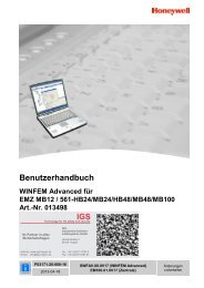
Bedienungs- und Installationsanleitung<br />
Operating and Installation Instruction<br />
Schlüsselschalter <strong>SS90</strong><br />
Key switch <strong>SS90</strong><br />
(Art.-Nr. / Part No. 154428 / 154430)<br />
798510.10<br />
07.2005<br />
G 193724 D GB<br />
Technische Änderungen<br />
vorbehalten!<br />
Technical changes reserved!
2 Schlüsselschalter <strong>SS90</strong><br />
Bestimmungsgemäßer Gebrauch<br />
Dieses Produkt darf nur für die im Katalog und in der technischen Beschreibung vorgesehenen<br />
Einsatzfälle und nur in Verbindung mit den von Esser by <strong>Honeywell</strong> empfohlenen<br />
bzw. zugelassenen Fremdgeräten und Komponenten verwendet werden.<br />
Warnung<br />
Der einwandfreie und sichere Betrieb des Produktes setzt sachgemäßen<br />
Transport, sachgerechte Lagerung, Aufstellung und Montage sowie sorgfältige Bedienung<br />
voraus.<br />
Sicherheitstechnische Hinweise für den Benutzer<br />
Diese Anleitung enthält die erforderlichen Informationen für den bestimmungsgemäßen<br />
Gebrauch der darin beschriebenen Produkte.<br />
Qualifiziertes Personal im Sinne der sicherheitsbezogenen Hinweise in dieser Anleitung<br />
oder auf das Produkt selbst sind Personen, die<br />
• entweder als Projektierungspersonal mit den Sicherheitsrichtlinien der<br />
Gefahrenmeldetechnik vertraut sind.<br />
• als Wartungspersonal im Umgang mit Einrichtungen der Einbruchmeldeanlagen<br />
unterwiesen sind und den auf die Bedienung bezogenen Inhalt dieser Anleitung<br />
kennen.<br />
• als Errichter- und Servicepersonal eine zur Reparatur derartiger Einrichtungen<br />
der Einbruchmeldetechnik befähigende Ausbildung besitzen bzw. die Berechtigung<br />
haben, Stromkreise und Geräte/Systeme gemäß den Standards der Sicherheitstechnik<br />
in Betrieb zu nehmen, zu erden und zu kennzeichnen.<br />
Gefahrenhinweise<br />
Die folgenden Hinweise dienen einerseits Ihrer persönlichen Sicherheit und andererseits<br />
der Sicherheit vor Beschädigung des beschriebenen Produktes oder angeschlossener<br />
Geräte.<br />
Sicherheitshinweise und Warnungen zur Abwendung von Gefahren für Leben und<br />
Gesundheit von Benutzern oder Instandhaltungspersonal bzw. zur<br />
Vermeidung von Sachschäden werden in dieser Anleitung durch die hier<br />
definierten Piktogramme hervorgehoben. Die verwendeten Piktogramme haben im<br />
Sinne der Anleitung selbst folgende Bedeutung:<br />
Bedeutet, dass Tod, schwere Körperverletzung oder erheblicher Sachschaden<br />
eintreten können, wenn die entsprechenden Vorsichtsmaß-nahmen nicht<br />
getroffen werden.<br />
Ist eine wichtige Information zu dem Produkt oder einem Teil der<br />
Anleitung auf den besonders aufmerksam gemacht werden soll.<br />
Ist eine wichtige Richtlinie gemäß der VdS Schadenverhütung GmbH, Köln.<br />
Bei einer VdS-gemäßen Programmierung der Gefahrenmeldeanlage ist dieser<br />
Teil besonders aufmerksam durchzulesen und einzuhalten.<br />
Demontage<br />
Gemäß Richtlinie 2002/96/EG (WEEE) wird das elektrische und<br />
elektronische Gerät nach der Demontage zur fachgerechten Entsorgung vom<br />
Hersteller zurückgenommen!
Schlüsselschalter <strong>SS90</strong> 3<br />
Ianhaltsverzeichnis<br />
Seite<br />
1 Allgemein .........................................................................................4<br />
2 Übersicht..........................................................................................5<br />
2.1 Montage- und Installationshinweise.......................................7<br />
2.2 Funktionsänderung Schalter S4 ............................................8<br />
2.3 Montage Profilhalbzylinder ....................................................9<br />
3 Technische Daten ..........................................................................10<br />
4 Anschaltung ...................................................................................11<br />
4.1 Einbruchmelde-Computer 5004/6 und<br />
Gefahrenmelde-Computer 2001 ..........................................13<br />
4.2 Einbruchmelde-Computer 5008...........................................14<br />
4.3 Einbruchmelde-Computer Serie HB / MB ............................15
4 Schlüsselschalter <strong>SS90</strong><br />
1 Allgemein<br />
Der Schlüsselschalter <strong>SS90</strong> ist eine universal einsetzbare Schalteinrichtung.<br />
Vorzugsweise wird diese zum Scharf-/Unscharfschalten von Einbruchmelderzentralen<br />
(VdS-Klasse A) verwendet.<br />
Leistungsmerkmale<br />
• Kernziehschutz<br />
• zwei optische Kontrollanzeigen<br />
• Summer als akustische Quittierung<br />
• Anbohrschutz (Option)<br />
• zweiter Schaltkontakt (nur Art.-Nr. 154430)<br />
• geeignet zur aP-, uP- oder Hohlwandmontage<br />
Lieferbare Ausführungen<br />
• Schlüsselschalter Art.-Nr. 154428<br />
• Schlüsselschalter mit zweitem Schaltkontakt Art.-Nr. 154430<br />
• Anbohrschutz (Option) Art.-Nr. 154437<br />
VdS-Anerkennung nur mit zugelassenen Profilzylindern und<br />
Anbohrschutz!<br />
Bei der VdS-gemäßen Installation sind die Richtlinien der Klasse A<br />
(VdS 2248 und 2311) zu beachten!<br />
Hohlwandeinbau bei VdS-Anlagen nicht zulässig!<br />
Lieferumfang<br />
• Schlüsselschalter <strong>SS90</strong><br />
• Sechskant-Schlüssel<br />
• 1 Innen-Sechskant-Schraube für Profilzylinderbefestigung<br />
• Widerstände (10 KΩ / 12K1)<br />
• 1 Steckbrücke<br />
• Dübel S6 inkl. zugehörige Befestigungsschrauben<br />
• Kabelbinder für Zugentlastung<br />
• Unterlegstreifen 1mm und 0,5 mm<br />
• Erdungskabel<br />
• Bedienungs- und Installationsanleitung
Schlüsselschalter <strong>SS90</strong> 5<br />
2 Übersicht<br />
V3<br />
V1<br />
X2<br />
H1<br />
S10<br />
ON<br />
X1<br />
R6<br />
R7<br />
R5<br />
R4<br />
1 2 3 4 5 6 7 8<br />
R8<br />
R8<br />
S4<br />
X4<br />
S1<br />
BR8<br />
S3<br />
S2<br />
SoFu S/U<br />
NO C +LED- +SUM- +LED- NC C S/U<br />
NO<br />
frei<br />
BR9 X3<br />
Sabo<br />
X5<br />
A B 1 2 3 4 5 6 7 8 9 10 11 12<br />
A B C<br />
Abb. 1: Übersicht und Lage der Bauelemente
6 Schlüsselschalter <strong>SS90</strong><br />
V1<br />
V3<br />
H1<br />
LED Anzeige - rot<br />
LED Anzeige - gelb<br />
Summer<br />
S10 DIL-Schalter-Stellung abhängig von der angeschlossenen<br />
Zentrale (siehe auch Widerstandswert R4 bis R8)<br />
(Kodierung siehe Kapitel 4)<br />
BR8 Löt- /Kratzbrücke - Mikroschalter S 1<br />
(Kodierung siehe Kapitel 4)<br />
BR9<br />
R4<br />
bis<br />
R8<br />
R8<br />
R8<br />
S1<br />
S2<br />
S3<br />
S4<br />
X1/X2<br />
X3<br />
werkseitige Einstellung<br />
1 2 3<br />
Löt- /Kratzbrücke - Anbohrschutz<br />
werkseitige Einstellung<br />
Optionale Einstellung<br />
Anbohrschutz nicht aktiviert<br />
Anbohrschutz aktiviert<br />
Widerstände werkseitig nicht bestückt (im Beipack).<br />
Bestückung sowie Widerstandswert abhängig von der<br />
angeschlossenen Zentrale (siehe auch DIL-Schalter-Stellung)<br />
Parallelschaltung von Widerständen bei EMZ der Serie HB/MB<br />
zur Widerstandsanpassung möglich<br />
zweiter Schaltkontakt werkseitig als Schließer-Kontakt<br />
(mit BR8 Kodierung als Öffner)<br />
Sabotage-Abrisskontakt<br />
Sabotage-Deckelkontakt<br />
Dauer- oder Tastkontakt für Scharf-/Unscharfschaltung<br />
(werkseitig Dauerkontakt, Montage- und Installationshinweise<br />
beachten)<br />
Flachkabelverbindung<br />
Anschluss Anbohrschutz - BR9 beachten!<br />
X4 Abrisskontakt S2 - bei Hohlwandeinbau ohne Funktion Brücke X4<br />
schließen (Steckbrücken im Beipack)<br />
X5 Anschlussklemmleiste (A, B, 1 bis 12)<br />
A<br />
B<br />
C<br />
Zugentlastung für das Anschlusskabel<br />
Betriebserde Gehäusedeckel<br />
Kabeleinführung
Schlüsselschalter <strong>SS90</strong> 7<br />
2.1 Montage- und Installationshinweise<br />
2<br />
1<br />
3<br />
4<br />
5<br />
6<br />
7<br />
Abb. 1: Installationshinweis<br />
8<br />
<br />
<br />
<br />
<br />
<br />
<br />
<br />
<br />
Betriebserde<br />
Sicherheitsschrauben und Zahnscheiben<br />
Gehäusedeckel<br />
Anbohrschutz (Option)<br />
aP-Gehäuse<br />
Dekor-Rahmen zusammen mit uP-Dose für uP-Wandeinbau<br />
(Art.-Nr. 154438) oder zusammen mit Spangen für Hohlwandeinbau<br />
(Art.-Nr. 154439) verwenden<br />
Spangen<br />
uP-Dose
8 Schlüsselschalter <strong>SS90</strong><br />
Installation<br />
• Gehäusedeckel und Abbohrschutz (falls vorhanden) entfernen.<br />
• Anschlusskabel einführen.<br />
• Gehäuse auf der Montagefläche ohne mechanische Verspannung mit<br />
4 Schrauben befestigen.<br />
• Bei Hohlwand- bzw. uP-Wandeinbau, die den Bausätzen beiliegende<br />
Installationsanleitung beachten.<br />
• Nach vollständiger Installation, Gehäuse mit den Sicherheitsschrauben<br />
verschließen.<br />
Das Gehäuse mit Dekorrahmen steht im eingeputzten Zustand<br />
ca. 17 mm vor.<br />
2.2 Funktionsänderung Schalter S4<br />
Werkseitig wird der Schlüsselschalter als Dauerkontakt/Schalter mit eingesetztem<br />
Bügel ausgeliefert. Soll der Schlüsselschalter als Tastkontakt/Taster<br />
verwendet werden, ist der Bügel zu entfernen.<br />
Feder zusammendrücken und Bügel entfernen<br />
Bügel<br />
S 4<br />
Feder<br />
Abb. 2: Funktionsänderung Schalter S4
Schlüsselschalter <strong>SS90</strong> 9<br />
2.3 Montage Profilhalbzylinder<br />
Mit der beiliegenden Innen-Sechskant-Schraube den Profilhalbzylinder im<br />
Gehäuse befestigen. Unterschiedliche Zylinderlängen werden mit den<br />
selbstklebenden Unterlegstreifen ausgeglichen (siehe Tabelle).<br />
Der Profilhalbzylinder muss mit dem Gehäusedeckel bündig<br />
abschließen. Zusätzlich ist bei der Montage des Profilhalbzylinders,<br />
die Schließnasenstellung zu beachten!<br />
Gehäuseboden<br />
Unterlegstreifen<br />
Zylinderlänge<br />
nach DIN<br />
10±1<br />
Zylinderlänge<br />
(mm)<br />
Unterlegstreifen<br />
weiß 1 mm<br />
farbig 0,5 mm<br />
28,5 - 29,0 3 1<br />
29,1 - 29,5 3 ---<br />
29,6 - 30,0 2 1<br />
30,1 - 30,5 2 ---<br />
30,6 - 31,0 1 1<br />
31,1 - 31,5 1 ---<br />
31,6 - 32,0 --- 1<br />
32,1 - 32,5 --- ---<br />
Abb. 3: Montage Profilhalbzylinder<br />
Schließnasenstellung<br />
Ruhestellung<br />
links 90° / links 135°<br />
Abb. 4: Schließnasenstellung<br />
Aktivierung<br />
scharf / unscharf<br />
Aktivierung<br />
Sonderfunktionen<br />
VdS-Anerkennung nur mit zugelassenen Profilzylindern und<br />
Anbohrschutz!
10 Schlüsselschalter <strong>SS90</strong><br />
3 Technische Daten<br />
Betriebsspannungsbereich : 8 V DC bis 18 V DC<br />
Nennspannung : 12 V DC<br />
Kontaktbelastung<br />
Schalter S1 bis S4 : max. 30 V DC / 500 mA<br />
Stromaufnahme : je LED : ca. 20 mA<br />
Summer : ca. 5 mA<br />
optische Anzeigen : LED, rot / LED, gelb<br />
akustischer Signalgeber : Summer 60 dB (A) / 1 m<br />
Anschlussklemmen : max. 1 mm²<br />
Umgebungstemperatur : -25 °C bis +70 °C<br />
Lagertemperatur : -30 °C bis +75 °C<br />
Umweltklasse : IV (gemäß VdS)<br />
Schutzart : IP 54<br />
Gehäuse : Zink-Druckguss<br />
Farbe : weiß (ähnlich RAL 9001)<br />
Gewicht : ca. 1250 g<br />
Maße (B x H x T)<br />
aP-Gehäuse : 88 x 142 x 54 (mm)<br />
uP-Gehäuse mit Dekorrahmen : 124 x 182 x 54 (mm)<br />
uP-Dose : 105 x 155 x 45 (mm)<br />
VdS-Anerkennung : G 193724, Klasse A<br />
Zubehör<br />
Bezeichnung<br />
Art.-Nr.<br />
Bausatz uP-Wandeinbau 154438<br />
Bausatz Hohlwandeinbau 154439<br />
Sicherheitsschraube 790725<br />
Spezial-Sechskantschlüssel 797027<br />
Weiteres Zubehör siehe Produktgruppenkatalog Einbruchmeldetechnik
Schlüsselschalter <strong>SS90</strong> 11<br />
4 Anschaltung<br />
Prinzipschaltung (werkseitige Einstellung)<br />
Schließung:<br />
BR8<br />
1<br />
R8<br />
S10<br />
7<br />
S1<br />
R7<br />
S10<br />
6<br />
S4<br />
S10<br />
3<br />
R4<br />
2<br />
3<br />
S10<br />
8<br />
S10<br />
4<br />
R6<br />
S10<br />
5<br />
S10<br />
2<br />
R5<br />
S10<br />
1<br />
S3<br />
X4<br />
S2<br />
X3<br />
BR9<br />
X5 A B 7 8 9 X5 10 11 12<br />
Beispiel:<br />
Schalterstellung S10<br />
(DIP-Schalter)<br />
Schließung<br />
ON<br />
1 2 3 4 5 6 7 8<br />
Sabotage<br />
on = off =<br />
Akustische / optische Signalgeber<br />
V3<br />
H1 +<br />
V1<br />
560<br />
560<br />
X5 1 2 3 4 5 6<br />
+ - + - + -<br />
LED gelb Summer LED rot
12 Schlüsselschalter <strong>SS90</strong><br />
Anschaltmöglichkeiten<br />
Einbruchmelde-/Gefahrenmelde-Computer<br />
EMZ<br />
5004/6<br />
EMZ EMZ<br />
5008 1) HB/MB 2)<br />
--- --- ---<br />
EMZ<br />
HB/MB 3)<br />
unscharf<br />
GMA<br />
2001<br />
--- --- --- 12K1 ---<br />
---<br />
Schlüsselschalter<br />
<strong>SS90</strong><br />
Klemmleiste X5<br />
12K1<br />
A<br />
B<br />
Sum AE1 + --- --- 12 V DC<br />
GND AE1 - --- --- TR 1<br />
Sum AE1 + --- --- 12 V DC<br />
GND AE1 - --- --- TR 3<br />
+<br />
LED rot<br />
-<br />
+<br />
Summer<br />
-<br />
5<br />
6<br />
3<br />
4<br />
TR 14 --- --- --- 12 V DC<br />
GND --- --- --- TR 3<br />
--- --- unscharf --- ---<br />
X20 - MG2 + 0 V 0 V MG 4 -<br />
X20 + MG2 - scharf scharf MG 4 +<br />
X6 - MG3 + Sabo Sabo MG 3 -<br />
--- 10KΩ 12K1 12K1 ---<br />
X6 + MG3 - Sabo Sabo MG 3 +<br />
+ 1<br />
LED gelb<br />
- 2<br />
Ö 7<br />
S4 G 8<br />
S 9<br />
10 frei<br />
R 11<br />
Sabotage<br />
12<br />
Folgende Anschlussbelegung ist erforderlich für,<br />
1) EMA esserbus ® -Koppler 5 Eingänge / 3 Ausgänge (Art.-Nr. 384620) an<br />
dem Einbruchmelde-Computer 5008<br />
2) Funktion Blockschlossersatz an EMZ Serie HB/MB<br />
3) Funktion Bedienteil an EMZ Serie HB/MB
Schlüsselschalter <strong>SS90</strong> 13<br />
4.1 Einbruchmelde-Computer 5004/6 und<br />
Gefahrenmelde-Computer 2001<br />
10kΩ unscharf / 5kΩ scharf – Schaltung<br />
Schlüsselschalter S4 : Dauerkontakt (werkseitig)<br />
Anschlussklemmen : siehe Kapitel 4<br />
Schalterstellung S10<br />
(DIP-Schalter)<br />
erforderliche<br />
Widerstände<br />
:<br />
ON<br />
1 2 3 4 5 6 7 8<br />
: R4, R5 = 10kΩ<br />
Impulsbetriebener Steuereingang<br />
Schlüsselschalter S4 : Tastkontakt<br />
Anschlussklemmen : siehe Kapitel 4<br />
Schalterstellung S10<br />
(DIP-Schalter)<br />
erforderliche<br />
Widerstände<br />
:<br />
ON<br />
1 2 3 4 5 6 7 8<br />
: R5 = 10kΩ
10K<br />
X5<br />
frei<br />
GND<br />
UB1<br />
UB2<br />
14 Schlüsselschalter <strong>SS90</strong><br />
4.2 Einbruchmelde-Computer 5008<br />
Zum Anschluss ist der EMA esserbus ® -Koppler 5 Eingänge /<br />
3 Ausgänge (Art.-Nr. 384620) erforderlich<br />
Schlüsselschalter S4 : Tastkontakt<br />
Anschlussklemmen : siehe auch Kapitel 4<br />
Schalterstellung S10<br />
(DIP-Schalter)<br />
erforderliche<br />
Widerstände<br />
:<br />
ON<br />
1 2 3 4 5 6 7 8<br />
: R4, R5 = 10kΩ<br />
V3<br />
V1<br />
X2<br />
H1<br />
X2<br />
-Lin+ -Lout+ -AE3+ +G1-<br />
X6<br />
S10<br />
ON<br />
1 2 3 4 5 6 7 8<br />
R8<br />
R8<br />
X1<br />
R6<br />
R7<br />
10K<br />
10K<br />
X4<br />
R5<br />
R4<br />
S4<br />
EMA esserbus ®<br />
Koppler<br />
5 Eingänge/<br />
3 Ausgänge<br />
Art.-Nr. 384620<br />
F2 F1<br />
S1 X5<br />
X4 X3<br />
S1<br />
BR8<br />
S3<br />
S2<br />
K1<br />
K2<br />
SoFu S/U<br />
NO C +LED- +SUM- +LED- NC C S/U<br />
NO<br />
BR9 X3<br />
Sabo<br />
A B 1 2 3 4 5 6 7 8 9 10 11 12<br />
X1<br />
+G2- +G3- +G4- +G5- +AE1- +AE2-<br />
Weiterführende Informationen zur Kundendatenprogrammierung<br />
und zum esserbus ® -Koppler sind den zugehörigen Dokumentationen<br />
zu entnehmen.
Schlüsselschalter <strong>SS90</strong> 15<br />
4.3 Einbruchmelde-Computer Serie HB / MB<br />
Funktion Blockschlossersatz<br />
Schlüsselschalter S4 : Dauerkontakt (werkseitig)<br />
Schließzylinder : Nasenstellung 90° links oder 135° links<br />
Anschlussklemmen : siehe Kapitel 4<br />
Schalterstellung S10<br />
(DIP-Schalter)<br />
erforderliche<br />
Widerstände<br />
:<br />
ON<br />
1 2 3 4 5 6 7 8<br />
: R5, R6 = 12k1<br />
V3<br />
V1<br />
X2<br />
H1<br />
Einbruchmelde-Computer<br />
Serie HB/MB<br />
S10<br />
ON<br />
1 2 3 4 5 6 7 8<br />
R8<br />
R8<br />
S1<br />
X1<br />
R6<br />
12K1<br />
R7<br />
12K1 R5<br />
R4<br />
S4<br />
X4<br />
S2<br />
Rechnerkarte<br />
SP<br />
SABO<br />
SABO<br />
UNSCH<br />
SCHARF<br />
+12V DC<br />
0V<br />
12K1<br />
BLOCKSCHLOSS<br />
ERDUNG<br />
BR8<br />
S3<br />
SoFu S/U<br />
NO C +LED- +SUM- +LED- NC C S/U<br />
NO<br />
frei<br />
BR9 X3<br />
Sabo<br />
X5<br />
A B 1 2 3 4 5 6 7 8 9 10 11 12
16 Schlüsselschalter <strong>SS90</strong><br />
Funktion Bedienteil<br />
Mikroschalter S1 : Tastkontakt<br />
Schlüsselschalter S4 : Tastkontakt<br />
Schließzylinder : Nasenstellung 135° links<br />
Löt-Kratz Brücke<br />
BR8<br />
: werkseitige Einstellung<br />
Anschlussklemmen : siehe Kapitel 4<br />
Schalterstellung S10<br />
(DIP-Schalter)<br />
erforderliche<br />
Widerstände<br />
:<br />
ON<br />
1 2 3 4 5 6 7 8<br />
: R4 = 12k1<br />
1 2 3<br />
V3<br />
V1<br />
X2<br />
H1<br />
Einbruchmelde-Computer<br />
Serie HB/MB<br />
S10<br />
ON<br />
1 2 3 4 5 6 7 8<br />
R8<br />
R8<br />
S1<br />
X1<br />
R6<br />
R7<br />
R5<br />
12K1 R4<br />
S4<br />
X4<br />
S2<br />
Rechnerkarte<br />
SP<br />
SABO<br />
SABO<br />
UNSCH<br />
SCHARF<br />
+12V DC<br />
0V<br />
BLOCKSCHLOSS<br />
ERDUNG<br />
BR8<br />
S3<br />
SoFu S/U<br />
NO C +LED- +SUM- +LED- NC C S/U<br />
NO<br />
BR9 X3<br />
Sabo<br />
A B 1 2 3 4 5 6 7 8 9 10 11 12<br />
12K1<br />
12K1<br />
frei<br />
X5
Schlüsselschalter <strong>SS90</strong> 17
18 Schlüsselschalter <strong>SS90</strong>
Operating and Installation Instruction<br />
Key switch <strong>SS90</strong><br />
(Part No. 154428 / 154430)<br />
798510.10<br />
07.2005<br />
G 193724 GB Technical changes reserved!
20 Key switch <strong>SS90</strong><br />
Intended purpose<br />
This product must only be used for the applications outlined in the catalogue and<br />
the technical description and in combination with external components and<br />
systems which have been approved or recommended by Esser by <strong>Honeywell</strong>.<br />
Warning<br />
In order to ensure correct and safe operation of the product, all guidelines<br />
concerning its transport, storage, installation, and mounting must be observed.<br />
This includes the necessary care in operating the product.<br />
Safety-relevant user information<br />
This manual includes all information required for the proper use of the products<br />
described.<br />
The term 'qualified personnel' in the context of the safety information included in<br />
this manual or on the product itself designates:<br />
• project engineers who are familiar with the safety guidelines concerning<br />
intruder alarm systems.<br />
• trained service engineers who are familiar with the components of intruder<br />
systems and the information on their operation as included in this manual.<br />
• trained installation or service personnel with the necessary qualification for<br />
carrying out repairs on intruder alarm systems or who are authorised to<br />
operate, ground and label electrical circuits and/or safety<br />
equipment/systems.<br />
Safety warnings<br />
The following information is given in the interest of your personal safety and to<br />
prevent damage to the product described in this manual and all equipment<br />
connected to it.<br />
Safety information and warnings for the prevention of dangers putting at risk the<br />
life and health of user and maintenance personnel as well as causing damage to<br />
the equipment itself are marked by the following pictograms. Within the context<br />
of this manual, these pictograms have the following meanings:<br />
Designates risks for man and/or machine. Non-compliance will create<br />
risks to man and/or machine. The level of risk is indicated by the word of<br />
warning:<br />
Important information on a topic or a procedure and other important<br />
information!<br />
This is an important guideline issued by VdS Schadenverhütung GmbH,<br />
Cologne. If the hazard alarm system is programmed in compliance with VdS,<br />
this section must be read very carefully and all instructions must be adhered<br />
to.<br />
Dismantling<br />
In accordance with Directive 2002/96/EG (WEEE), after being dismantled,<br />
electrical and electronic equipment is taken back by the manufacturer for<br />
proper disposal.
Key switch <strong>SS90</strong> 21<br />
Table of contents<br />
Page<br />
1 General .......................................................................................22<br />
2 Overview .....................................................................................23<br />
2.1 Assembly and installation information ............................... 25<br />
2.2 Modified function for switch S4.......................................... 26<br />
2.3 Assembly of half cylinder ................................................... 27<br />
3 Technical specifications ..............................................................28<br />
4 Wiring..........................................................................................29<br />
4.1 Intruder alarm panel 5004/6 and<br />
hazard alarm computer 2001............................................. 31<br />
4.2 Intruder alarm panel 5008.................................................. 32<br />
4.3 Intruder alarm panel HB/MB Series................................... 33
22 Key switch <strong>SS90</strong><br />
1 General<br />
Key switch SS 90 is a switching system with universal uses. It is preferably<br />
used to arm/disarm burglar alarm systems (VdS Class A).<br />
Features<br />
• Cylinder protection<br />
• Two visual control displays<br />
• Buzzer for acoustic acknowledgement<br />
• Power drill protection (optional)<br />
• Second switch contact (only Part No. 154430)<br />
• Suitable for surface, flush or cavity wall mounting<br />
Types available<br />
• Key switch Part No. 154428<br />
• Key switch with second switch contact Part No. 154430<br />
• Power drill protection (optional) Part No. 154437<br />
VdS approval only with approved profile cylinder and drilling<br />
protection!<br />
In case of VdS-approved installation, the guidelines of Class A (VdS<br />
2248 and 2311) must be complied with!<br />
In VdS systems, cavity wall installation is not permitted.<br />
Scope of delivery<br />
• Key switch <strong>SS90</strong><br />
• Hexagonal spanner<br />
• 1 Allan screw to attach the profile cylinder<br />
• Resistors (10 KΩ / 12K1)<br />
• 1 bridge<br />
• S6 plugs, including fixing screws<br />
• Cable fasteners for strain relief<br />
• 1mm and 0.5mm underlay strips<br />
• Grounding cable<br />
• Operating and installation instructions
Key switch <strong>SS90</strong> 23<br />
2 Overview<br />
V3<br />
V1<br />
X2<br />
H1<br />
S10<br />
ON<br />
X1<br />
R6<br />
R7<br />
R5<br />
R4<br />
1 2 3 4 5 6 7 8<br />
R8<br />
R8<br />
X4<br />
S4<br />
S1<br />
BR8<br />
S3<br />
S2<br />
SoFu S/U<br />
NO C +LED- +SUM- +LED- NC C S/U<br />
NO<br />
frei<br />
BR9 X3<br />
Sabo<br />
X5<br />
A B 1 2 3 4 5 6 7 8 9 10 11 12<br />
A B C<br />
Fig. 1: Overview and position of the components
24 Key switch <strong>SS90</strong><br />
V1<br />
V3<br />
H1<br />
S10<br />
BR8<br />
BR9<br />
R4<br />
to<br />
R8<br />
R8<br />
R8<br />
S1<br />
S2<br />
S3<br />
S4<br />
X1/X2<br />
X3<br />
LED display - red<br />
LED display - yellow<br />
Buzzer<br />
DIL switch setting depending on the panel that is connected<br />
(see also resistor value R4 to R8)<br />
(See Section 4 for coding)<br />
Solder jumper – micro switch S 1<br />
(Coding, see Section 4)<br />
Default setting<br />
1 2 3<br />
Solder jumper – power drill protection<br />
Default setting<br />
Optional setting<br />
Power drill protection not enabled<br />
Power drill protection enabled<br />
Resistors not inserted in default setting (in additional bag)<br />
Assembly and resistor value depends on the panel that is<br />
connected (see also DIL switch setting)<br />
Parallel connection of resistors for resistor adaptation possible<br />
in HB/MB Series IAPs<br />
In default setting second switch contact<br />
(with BR8 coding as opener)<br />
Tamper rupture contact<br />
Tamper lid contact<br />
as NO contact<br />
Sustained or momentary contact for arming/disarming (default is<br />
sustained contact, read assembly and installation instructions)<br />
Flat cable connection<br />
Power drill protection connection – pay attention to BR9!<br />
X4 Rupture contact S2<br />
in cavity wall installation without function<br />
(jumpers in additional bag)<br />
X5 Terminal strip (A, B, 1 to 12)<br />
A<br />
B<br />
C<br />
Strain relief for connection cable<br />
System ground housing lid<br />
Cable entry<br />
close X4 bridge
Key switch <strong>SS90</strong> 25<br />
2.1 Assembly and installation information<br />
2<br />
1<br />
3<br />
4<br />
5<br />
6<br />
7<br />
Fig. 1: Installation information<br />
8<br />
<br />
<br />
<br />
<br />
<br />
<br />
<br />
<br />
System ground<br />
Safety screws and tooth lock washers<br />
Housing lid<br />
Power drill protection (optional)<br />
Surface mounted housing<br />
Use decorative frame with flush mounted socket for flush<br />
mounted installation (Part No. 154438) or together with clasps <br />
for cavity wall installation (Part No. 154439)<br />
Clasps<br />
Flush mounted socket
26 Key switch <strong>SS90</strong><br />
Installation<br />
• Remove housing lid and power drill protection (if applicable)<br />
• Insert connection cable<br />
• Fix housing to the surface with 4 screws without any mechanical strain.<br />
• In the case of a cavity wall or flush mounted installation, read the<br />
enclosed installation instructions.<br />
• When installation is completed, close the housing with the locking<br />
screws.<br />
The housing with the decorative frame is raised approx. 17mm<br />
from the surface when the wall has been rendered.<br />
2.2 Modified function for switch S4<br />
In the default setting the key switch is delivered as a sustained<br />
contact/switch with inserted clamp. If the key switch is to be used as a<br />
momentary contact/non-locking key, remove the clamp.<br />
Compress the spring and remove the clamp<br />
Clamp<br />
S 4<br />
Spring<br />
Fig. 2: Modified function for switch S4
Key switch <strong>SS90</strong> 27<br />
2.3 Assembly of half cylinder<br />
Fix the half cylinder in the housing with the Allan screw. Balance out<br />
differing cylinder lengths with the adhesive underlay strips (see Table).<br />
The half cylinder must be flush with the housing lid. When you are<br />
assembling the half cylinder, pay attention to the latch setting.<br />
Underlay<br />
strip<br />
Cylinde length<br />
acc. to DIN<br />
10±1<br />
Housing<br />
base<br />
Cylinder length<br />
(mm)<br />
Underlay strip<br />
white 1 mm<br />
coloured 0.5<br />
mm<br />
28,5 - 29,0 3 1<br />
29,1 - 29,5 3 ---<br />
29,6 - 30,0 2 1<br />
30,1 - 30,5 2 ---<br />
30,6 - 31,0 1 1<br />
31,1 - 31,5 1 ---<br />
31,6 - 32,0 --- 1<br />
32,1 - 32,5 --- ---<br />
Fig. 3: Assembly of half cylinder<br />
Latch position<br />
Idle position<br />
left 90° / left 135°<br />
Fig. 4: Latch position<br />
Activation<br />
armed / disarmed<br />
Activation<br />
special functions<br />
VdS approval only with approved profile cylinder and drilling<br />
protection!
28 Key switch <strong>SS90</strong><br />
3 Technical specifications<br />
Power supply range : 8 V DC to 18 V DC<br />
Rated voltage : 12 V DC<br />
Contact load<br />
switch S1 to S4 : max. 30 V DC / 500 mA<br />
Current consumption : per LED: approx. 20 mA<br />
Buzzer: approx. 5 mA<br />
Optical indicators : LED, ret / LED, yellow<br />
Audible alarm device : Buzzer 60 dB (A) / 1 m<br />
Terminals : max. 1 mm²<br />
Ambient temperature : -25 °C to +70 °C<br />
Storage temperature : -30 °C to +75 °C<br />
Environmental rating : IV (according to VdS)<br />
Protection rating : IP 54<br />
Housing : die-cast zinc<br />
Colour : white (similar RAL 9001)<br />
Weight : approx. 1250 g<br />
Dimension (w x h x d)<br />
Surface-mount housing : 88 x 142 x 54 (mm)<br />
Flush mounting box incl.<br />
:<br />
decorative frame<br />
124 x 182 x 54 (mm)<br />
Flush mounting box : 105 x 155 x 45 (mm)<br />
VdS approval : G 193724, Class A<br />
Accessories<br />
Discription<br />
Part No.<br />
Flush-mounted installation kit 154438<br />
Cavity wall installation kit 154439<br />
Safety screew 790725<br />
Special hexagonal spanner 797027<br />
Refer to the Intruder Alarm System Catalogue for additional<br />
accessories.
Key switch <strong>SS90</strong> 29<br />
4 Wiring<br />
Schematic circuit diagram (default setting)<br />
Closure<br />
BR8<br />
1<br />
R8<br />
S10<br />
7<br />
S1<br />
R7<br />
S10<br />
6<br />
S4<br />
S10<br />
3<br />
R4<br />
2<br />
3<br />
S10<br />
8<br />
S10<br />
4<br />
R6<br />
S10<br />
5<br />
S10<br />
2<br />
R5<br />
S10<br />
1<br />
S3<br />
X4<br />
S2<br />
X3<br />
BR9<br />
X5 A B X5 7 8 9 X5 10 11 12<br />
Closure Tamper<br />
Example:<br />
Switch position S10<br />
(DIP switch)<br />
ON<br />
1 2 3 4 5 6 7 8<br />
on = off =<br />
Audible/optical alarm device<br />
V3<br />
H1<br />
+<br />
V1<br />
560<br />
560<br />
X5 1 2 3 4 5 6<br />
LED yellow Buzzer LED red
30 Key switch <strong>SS90</strong><br />
Wiring alternatives<br />
IAP<br />
5004/6<br />
Intruder alarm/security alarm computer<br />
IAP IAP<br />
5008 1) HB/MB 2)<br />
IAP<br />
HB/MB 3)<br />
HAP<br />
2001<br />
--- --- --- disarmed ---<br />
--- --- --- 12K1 ---<br />
AE1<br />
Buzz<br />
--- --- 12 V DC<br />
(+)<br />
GND AE1 - --- --- TR 1<br />
Buzz AE1 + --- --- 12 V DC<br />
GND AE1 - --- --- TR 3<br />
TR 14 --- --- --- 12 V DC<br />
GND --- --- --- TR 3<br />
--- --- disarmed --- ---<br />
X20 - MG2 + 0 V 0 V MG 4 -<br />
X20 + MG2 - armed armed MG 4 +<br />
X6 - MG3 + Tamper Camper MG 3 -<br />
--- 10KΩ 12K1 12K1 ---<br />
X6 + MG3 - Tamper Tamper MG 3 +<br />
Key switch<br />
<strong>SS90</strong><br />
Terminal strip X5<br />
12K1<br />
A<br />
B<br />
+ 5<br />
LED red<br />
- 6<br />
+ 3<br />
Buzzer<br />
- 4<br />
+ 1<br />
LED yellow<br />
- 2<br />
Ö 7<br />
S4 G 8<br />
S 9<br />
R<br />
10 spare<br />
11<br />
12<br />
Tamper<br />
The following terminal assignment is necessary for<br />
1) IAP transponder 5 inputs/3 outputs (Part No. 384620) on the intruder<br />
alarm panel 5008<br />
2) the shunt lock replacement function on IAP Series HB/MB<br />
3) the operating panel function on IAP Series HB/MB
Key switch <strong>SS90</strong> 31<br />
4.1 Intruder alarm panel 5004/6 and<br />
hazard alarm computer 2001<br />
10kΩ disabled/ 5kΩ enabled connection<br />
Key switch S4 : Sustained contact (default)<br />
Terminals : see Section 4<br />
Switch position S10<br />
(DIP switch)<br />
:<br />
ON<br />
1 2 3 4 5 6 7 8<br />
Required resistors : R4, R5 = 10kΩ<br />
Pulse actuated control input<br />
Key switch S4 : Momentary contact<br />
Terminals : see Section 4<br />
Switch position S10<br />
(DIP switch)<br />
:<br />
ON<br />
1 2 3 4 5 6 7 8<br />
Required resistors : R5 = 10kΩ
10K<br />
X5<br />
frei<br />
GND<br />
UB1<br />
UB2<br />
32 Key switch <strong>SS90</strong><br />
4.2 Intruder alarm panel 5008<br />
The IAP transponder 5 inputs/3 outputs (Part No. 384620) is required<br />
for the connection.<br />
Key switch S4 : Momentary contact<br />
Terminals : see also Section 4<br />
Switch position S10<br />
(DIP switch)<br />
Required resistors<br />
:<br />
ON<br />
1 2 3 4 5 6 7 8<br />
: R4, R5 = 10kΩ<br />
V3<br />
V1<br />
X2<br />
H1<br />
X2<br />
-Lin+ -Lout+ -AE3+ +G1-<br />
X6<br />
S10<br />
ON<br />
1 2 3 4 5 6 7 8<br />
R8<br />
R8<br />
X1<br />
R6<br />
R7<br />
10K<br />
10K<br />
X4<br />
R5<br />
R4<br />
S4<br />
IAP esserbus ®<br />
transponder<br />
5 Inputs/<br />
3 Outputs<br />
Part No. 384620<br />
F2 F1<br />
S1 X5<br />
X4 X3<br />
S1<br />
BR8<br />
S3<br />
S2<br />
K1<br />
K2<br />
SoFu S/U<br />
NO C +LED- +SUM- +LED- NC C S/U<br />
NO<br />
BR9 X3<br />
Sabo<br />
A B 1 2 3 4 5 6 7 8 9 10 11 12<br />
X1<br />
+G2- +G3- +G4- +G5- +AE1- +AE2-<br />
The associated documentation contains more information about<br />
customer data programming and about the transponders.
12K1<br />
X5<br />
frei<br />
Computer board<br />
Key switch <strong>SS90</strong> 33<br />
4.3 Intruder alarm panel HB/MB Series<br />
Shunt lock replacement function<br />
Key switch S4 : Sustained contact (default)<br />
Locking cylinder : Latch position 90° left or 135° left<br />
Terminals : see Section 4<br />
Switch position S10<br />
(DIP switch)<br />
Required resistors<br />
:<br />
ON<br />
1 2 3 4 5 6 7 8<br />
: R5, R6 = 12k1<br />
V3<br />
V1<br />
X2<br />
H1<br />
Intruder Alarm Computer<br />
Series HB/MB<br />
S10<br />
ON<br />
1 2 3 4 5 6 7 8<br />
R8<br />
R8<br />
S1<br />
X1<br />
R6<br />
12K1<br />
R7<br />
12K1 R5<br />
R4<br />
S4<br />
X4<br />
S2<br />
SP<br />
SABO<br />
SABO<br />
UNSCH<br />
SCHARF<br />
+12V DC<br />
0V<br />
BLOCKSCHLOSS<br />
ERDUNG<br />
BR8<br />
S3<br />
SoFu S/U<br />
NO C +LED- +SUM- +LED- NC C S/U<br />
NO<br />
BR9 X3<br />
Sabo<br />
A B 1 2 3 4 5 6 7 8 9 10 11 12
12K1<br />
12K1<br />
X5<br />
frei<br />
Computer board<br />
34 Key switch <strong>SS90</strong><br />
Operating panel function<br />
Micro switch S1 : Momentary contact<br />
Key switch S4 : Momentary contact<br />
Locking cylinder : Latch position 135° left<br />
Solder jumper BR8<br />
: Default setting<br />
Terminals : see Section 4<br />
Switch position S10<br />
(DIP switch)<br />
Required resistors<br />
:<br />
ON<br />
1 2 3 4 5 6 7 8<br />
: R4 = 12k1<br />
1 2 3<br />
V3<br />
V1<br />
X2<br />
H1<br />
Intruder Alarm Computer<br />
Series HB/MB<br />
S10<br />
ON<br />
1 2 3 4 5 6 7 8<br />
R8<br />
R8<br />
S1<br />
X1<br />
R6<br />
R7<br />
R5<br />
12K1 R4<br />
S4<br />
X4<br />
S2<br />
SP<br />
SABO<br />
SABO<br />
UNSCH<br />
SCHARF<br />
+12V DC<br />
0V<br />
BLOCKSCHLOSS<br />
ERDUNG<br />
BR8<br />
S3<br />
SoFu S/U<br />
NO C +LED- +SUM- +LED- NC C S/U<br />
NO<br />
BR9 X3<br />
Sabo<br />
A B 1 2 3 4 5 6 7 8 9 10 11 12
Key switch <strong>SS90</strong> 35
Novar GmbH<br />
a <strong>Honeywell</strong> Company<br />
Dieselstraße 2, D-41469 Neuss<br />
E-Mail : info@novar.de<br />
Internet: www.novar.de


