Kupplungen Couplings - WMH Herion
Kupplungen Couplings - WMH Herion
Kupplungen Couplings - WMH Herion

Erfolgreiche ePaper selbst erstellen
Machen Sie aus Ihren PDF Publikationen ein blätterbares Flipbook mit unserer einzigartigen Google optimierten e-Paper Software.
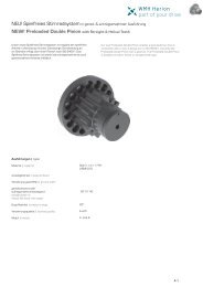
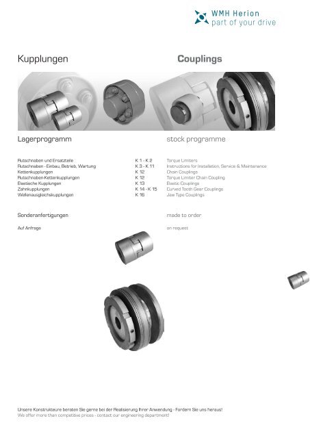
<strong>Kupplungen</strong><br />
<strong>Couplings</strong><br />
Lagerprogramm<br />
stock programme<br />
Rutschnaben und Ersatzteile<br />
Rutschnaben - Einbau, Betrieb, Wartung<br />
Kettenkupplungen<br />
Rutschnaben-Kettenkupplungen<br />
Elastische <strong>Kupplungen</strong><br />
Zahnkupplungen<br />
Wellenausgleichskupplungen<br />
K 1 - K 2<br />
K 3 - K 11<br />
K 12<br />
K 12<br />
K 13<br />
K 14 - K 15<br />
K 16<br />
Torque Limiters<br />
Instructions for Installation, Service & Maintenance<br />
Chain <strong>Couplings</strong><br />
Torque Limiter Chain Coupling<br />
Elastic <strong>Couplings</strong><br />
Curved Tooth Gear <strong>Couplings</strong><br />
Jaw Type <strong>Couplings</strong><br />
Sonderanfertigungen<br />
Auf Anfrage<br />
made to order<br />
on request<br />
Unsere Konstrukteure beraten Sie gerne bei der Realisierung Ihrer Anwendung - Fordern Sie uns heraus!<br />
We offer more than competitive prices - contact our engineering department!
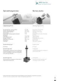
Rutschnaben<br />
Torque Limiters<br />
Typ 1 | type 1 Typ 2 | type 2<br />
M t<br />
[Nm]<br />
J<br />
[kg cm²]<br />
n max<br />
[min -1]<br />
Type A B C D D max<br />
H7<br />
F max F 1 G H K L M N e8 [kg] Bestell-Nr.<br />
Part No.<br />
55 1,8 6900 1 55 55 M35 x 1,5 9 24 9 7 M4 3 M6 40 11 40 0,4 296-000-005<br />
135 3,8 5500 1 70 62 M40 x 1,5 13 28 10 7,5 M4 3 M6 48 14 45 0,75 296-000-013<br />
320 10 4200 1 90 68 M45 x 1,5 18 32 16 13 M5 4,5 M6 60 18 50 1,3 296-000-032<br />
800 50 3000 1 125 100 M70 x 1,5 18 50 20 16,5 M6 5 M8 75 22 80 3,2 296-000-080<br />
1900 250 2200 1 170 145 M100 x 2 33 70 30 26 M8 6 M8 95 26 110 7,3 296-000-190<br />
2400 1400 1650 2 230 180 M140 x 2 43 95 35 30 M10 9 M8 150 35 150 25 296-000-240<br />
4800 1400 1650 2 230 180 M140 x 2 43 95 35 30 M10 9 M8 150 35 150 25 296-000-480<br />
6000 5350 1200 2 310 220 M170 x 3 68 120 40 34 M10 9 M8 180 45 185 44 296-000-600<br />
12000 5350 1200 2 310 220 M170 x 3 68 120 40 34 M10 9 M8 180 45 185 44 296-000-912<br />
Die <strong>WMH</strong>-Rutschnaben schützen Maschinen, deren Antriebe aus Kettenrädern,<br />
Zahnrädern oder Riemenscheiben bestehen, vor Überlastschäden.<br />
Die Rutschnaben sind robust, leicht einstellbar und einfach zu<br />
montieren. Sie übertragen Drehmomente in beide Drehrichtungen.<br />
Die organischen Reibbeläge sind verschleißfest, arbeiten trocken und<br />
bewirken eine kraftschlüssige Verbindung zwischen den An- und Abtriebselementen.<br />
Das gewünschte Drehmoment wird mit einer Stellmutter durch Anspannen<br />
von Tellerfedern eingestellt. Diese Tellerfedern können einfach oder<br />
mehrfach geschichtet sein (siehe Tellerfederschichtung). Dadurch ergibt<br />
sich eine verhältnismäßig genaue Drehmomenteinstellung zw. 7% und<br />
100% des max. Drehmoments. Die Rutschnaben sind vor Öl und Fett<br />
zu schützen. Das eingestellte Drehmoment, der Zustand der Reibbeläge<br />
sowie die Funktionsfähigkeit sind von Zeit zu Zeit zu kontrollieren.<br />
Die zum Einbau vorgesehenen Antriebselemente müssen an den Reibflächen<br />
planparallel (0,02 mm) mit einer max. Rauhtiefe von 6 µm sein.<br />
Der Gleitring ist den Übertragungselementen in der Breite anzupassen.<br />
The <strong>WMH</strong>-torque limiters protect machines, with drives of sprockets,<br />
gears or pulleys, against overload damage. The torque limiters are<br />
robust and easy to adjust and mount. They transmit torque in both directions.<br />
The friction (Discs) have good wearing, properties and from<br />
a good drive between input and output elements. The required torque<br />
can be selected by adjusting the nut and by positioning the spring<br />
cups. These spring cups can be simple or several times stacked<br />
(see spring cupstacking,Type 1 or Type 2).<br />
This results in a relatively exact adjusting of torque between 7% and<br />
100% of max. torque. The torque limiters should be protected from<br />
oil and grease. Torque rating condition of friction disc and performance<br />
should be checked from time to time. The mounted elements<br />
must have parallel mating surface (0,02 mm) with a max. peak-to-valley<br />
height of 6 µm. The breadth of the slide rings has to be adapted<br />
to the transmitting elements.<br />
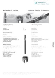
Tellerfederschichtung | spring cup stacking:<br />
Typ 1 | type 1<br />
Typ 2 | type 2<br />
Einfachschichtung<br />
single stacking<br />
Zweifachschichtung<br />
double stacking<br />
Dreifachschichtung<br />
triple stacking<br />
Zweifachschichtung<br />
double stacking<br />
Dreifachschichtung<br />
triple stacking<br />
Einfachgeschichtet<br />
single stacked<br />
Zweifachgeschichtet<br />
double stacked<br />
Dreifachgeschichtet<br />
triple stacked<br />
K 1<br />
Einstellbereich 7% bis 33% des max. Drehmoments<br />
adjustment range from 7% to 33% of max. torque<br />
Einstellbereich 33% bis 65% des max. Drehmoments<br />
adjustment range from 33% to 65% of max. torque<br />
Einstellbereich 65% bis 100% des max. Drehmoments<br />
adjustment range from 65% to 100% of max. torque
Ersatzteile für Rutschnaben<br />
Spare Parts for Torque Limiter<br />
für Rutschnabe (alt) für Rutschnabe (neu) Bezeichnung Anzahl je Rutschnabe Bestellnummer<br />
for torque limiter (old) for torque limiter (new) description quantity je torque Part No.<br />
limiter<br />
(alt-Gußteil | old-casting) ab Juni 06 | starting from june 06<br />
296-000-003 296-000-005 Reibbelag | friction lining 2 296-002-005<br />
296-000-008 296-000-013 Reibbelag | friction lining 2 296-002-013<br />
296-000-020 296-000-032 Reibbelag | friction lining 2 296-002-032<br />
296-000-050 296-000-080 Reibbelag | friction lining 2 296-002-080<br />
296-000-120 296-000-190 Reibbelag | friction lining 2 296-002-190<br />
296-000-160 296-000-240 Reibbelag | friction lining 2 296-002-240<br />
296-000-320 296-000-480 Reibbelag | friction lining 2 296-002-480<br />
296-000-400 296-000-600 Reibbelag | friction lining 2 296-002-600<br />
296-000-800 296-000-912 Reibbelag | friction lining 2 296-002-912<br />
296-000-003 296-000-005 Gleitring | slip ring 1 296-003-005<br />
296-000-008 296-000-013 Gleitring | slip ring 1 296-003-013<br />
296-000-020 296-000-032 Gleitring | slip ring 1 296-003-032<br />
296-000-050 296-000-080 Gleitring | slip ring 1 296-003-080<br />
296-000-120 296-000-190 Gleitring | slip ring 1 296-003-190<br />
296-000-160 296-000-240 Gleitring | slip ring 1 296-003-240<br />
296-000-320 296-000-480 Gleitring | slip ring 1 296-003-480<br />
296-000-400 296-000-600 Gleitring | slip ring 1 296-003-600<br />
296-000-800 296-000-912 Gleitring | slip ring 1 296-003-912<br />
x 296-000-005 Tellerfeder | spring cup 3 296-005-005<br />
x 296-000-013 Tellerfeder | spring cup 3 296-005-013<br />
x 296-000-032 Tellerfeder | spring cup 3 296-005-032<br />
x 296-000-080 Tellerfeder | spring cup 3 296-005-080<br />
x 296-000-190 Tellerfeder | spring cup 3 296-005-190<br />
x 296-000-240 Tellerfeder | spring cup 36 296-005-240<br />
x 296-000-480 Tellerfeder | spring cup 72 296-005-480<br />
x 296-000-600 Tellerfeder | spring cup 36 296-005-600<br />
x 296-000-912 Tellerfeder | spring cup 72 296-005-912<br />
296-000-003 x Tellerfeder | spring cup 3 296-005-003<br />
296-000-008 x Tellerfeder | spring cup 3 296-005-008<br />
296-000-020 x Tellerfeder | spring cup 3 296-005-020<br />
296-000-050 x Tellerfeder | spring cup 3 296-005-050<br />
296-000-120 x Tellerfeder | spring cup 3 296-005-120<br />
296-000-160 x Tellerfeder | spring cup 36 296-005-160<br />
296-000-320 x Tellerfeder | spring cup 72 296-005-320<br />
296-000-400 x Tellerfeder | spring cup 36 296-005-400<br />
296-000-800 x Tellerfeder | spring cup 72 296-005-800<br />
Bitte bei Bestellung die benötigte Stückzahl mit angeben.<br />
Please when ordering also indicate the necessary number of items.<br />
K 2
Rutschnaben - Anleitung für Einbau, Betrieb und Wartung<br />
Instructions for Installation, Service and Maintenance<br />
Einleitung:<br />
Rutschnaben sind Sicherheitselemente, die nachfolgende Bauteile<br />
im Antriebsstrang bei Überlast vor Zerstörung schützen. Dies sind<br />
hauptsächlich Maschinenantriebe mit Kettenrädern, Zahnrädern oder<br />
Riemenscheiben.<br />
Wird das mittels einer Stellmutter eingestellte Rutschmoment überschritten,<br />
rutscht die Kupplung durch und begrenzt somit das Drehmoment.<br />
Die Rutschnaben-Bestandteile sind allseitig bearbeitet und korrosionsgeschützt.<br />
General:<br />
Torque limiters are safety elements protecting connected machinery<br />
parts against destruction at overload, e.g. machinery drives<br />
with sprockets, geared wheels or pulleys.<br />
If the slipping torque being adjusted by an adjusting nut is<br />
exceeded, the torque limiter slips thus limiting the torque.<br />
Torque limiters are machined all over and protected against<br />
corrosion.<br />
Sicherheitshinweise:<br />
Durch rotierende Antriebselemente können Sie sich schwer verletzen.<br />
Beachten Sie unbedingt die folgenden Sicherheitshinweise und<br />
sorgen Sie für geeignete Schutzmaßnahmen.<br />
- Lesen Sie diese Anleitung sorgfältig durch, bevor Sie die Rutschnabe<br />
in Betrieb nehmen.<br />
- Die Montageanleitung ist Teil Ihres Produkts. Bewahren Sie diese<br />
sorgfältig in der Nähe der Rutschnabe auf.<br />
- Montage und Wartung sind ausschließlich durch geschultes Fachpersonal<br />
durchzuführen.<br />
- Die Rutschnabe darf nur bestimmungsgemäß und den technischen<br />
Daten entsprechend eingesetzt und verwendet werden.<br />
Safety regulations:<br />
Rotating power transmission elements can seriously hurt you.<br />
Strictly observe following safety regulations and arrange for<br />
proper protection.<br />
- Carefully read the instructions before putting the torque<br />
limiter into operation.<br />
- These instructions are part of the product. Keep them close<br />
to the torque limiter.<br />
- Assembly and maintenance are to be carried out by skilled<br />
personnel only.<br />
- Assemble and operate torque limiters within their predetermined<br />
application and their specified application limits only.<br />
Kundendienst:<br />
Sollten Sie die Hilfe unseres Kundendienstes benötigen:<br />
- nennen Sie die Auftrags-Nummer und die <strong>WMH</strong>-Artikelnummer<br />
- nennen Sie die Art und das Ausmaß der Störung<br />
- teilen Sie mit, wann und unter welchen Begleitumständen die<br />
Störung aufgetreten ist<br />
- nennen Sie die vermutete Ursache<br />
Customer service:<br />
Should you require assistance by our customer service would<br />
you please advise:<br />
- order number or type designation and size<br />
- kind and scope of malfunction<br />
- under which service conditions and when the malfunction<br />
arose<br />
- assumed reason for the malfunction<br />
K 3
Rutschnaben - Anleitung für Einbau, Betrieb und Wartung<br />
Instructions for Installation, Service and Maintenance<br />
Aufbau (Explosionsdarstellung Serie 296-000-005 bis -912) | Design (explosion drawing type 296-000-005 to -912)<br />
296-000-005 bis | to -190 296-000-240 bis | to -912<br />
Teileliste:<br />
1. Nabe<br />
2. Druckscheibe<br />
3. Belagscheibe<br />
4. Tellerfeder (Art. 296-000-005 bis -190)<br />
5. Stellmutter<br />
6. Gewindestift<br />
7. Gleitbuchse<br />
8. Sicherungsring<br />
9. Gewindestift<br />
10. Druckscheibe (Art. 296-000-240 bis -912)<br />
11. Druckscheibe (Art. 296-000-240 bis -912)<br />
12. Einstellring (Art. 296-000-240 bis -912)<br />
13. Tellerfeder (Art. 296-000-240 bis -912)<br />
14. Zylinderschraube (Art. 296-000-240 bis -912)<br />
Parts List:<br />
1. hub<br />
2. pressure plate<br />
3. friction lining<br />
4. cup spring (Art. 296-000-005 to -190)<br />
5. adjusting nut<br />
6. cylindrical pin<br />
7. siding bush<br />
8. snap ring<br />
9. cylindrical pin<br />
10. pressure plate (Art. 296-000-240 to -912)<br />
11. pressure plate (Art. 296-000-240 to -912)<br />
12. adjusting ring (Art. 296-000-240 to -912)<br />
13. cup spring (Art. 296-000-240 to -912)<br />
14. hexagon head screw (Art. 296-000-240 to -912)<br />
Tellerfederschichtung | Stack of cup springs:<br />
Einfach |<br />
single<br />
296-000-005 bis | to -190 296-000-240 bis | to -912<br />
Zweifach |<br />
double<br />
Dreifach |<br />
triple<br />
Zweifach |<br />
double<br />
Dreifach |<br />
triple<br />
K 4
Rutschnaben - Anleitung für Einbau, Betrieb und Wartung<br />
Instructions for Installation, Service and Maintenance<br />
Funktion:<br />
Rutschkupplungen sind Sicherheitselemente. Das übertragende<br />
Element (z.B. Kettenrad) wird zwischen den Belagscheiben angeordnet.<br />
Wird das eingestellte Rutschmoment überschritten, rutscht das<br />
Element durch.<br />
Als Anschlag für die Druckscheibe ist ein Sicherungsring eingebaut.<br />
Die erforderliche Anpresskraft für das Drehmoment wird durch<br />
Tellerfedern bzw. Druckfedern erzeugt.<br />
Tellerfedern / Druckfedern werden über eine Stellmutter vorgespannt.<br />
Bei größeren <strong>Kupplungen</strong> (ab <strong>WMH</strong>-Art. 296-000-240)<br />
unterstützen Hilfsschrauben die Einstellung der Stellmutter.<br />
Die <strong>Kupplungen</strong> sind als Standardausführung nur im Trockenlauf einsetzbar.<br />
Standardmäßig werden organische Reibbeläge verwendet.<br />
Montage:<br />
Beidseitige Montage und Demontage der Einzelteile ist bei allen<br />
Ausführungen möglich!<br />
- Die Reihenfolge der Montage ist der Explosionszeichnung (S. 2)<br />
zu entnehmen.<br />
- Achtung! Untersuchen Sie die Lieferung vor Montage auf<br />
Transportschäden.<br />
- Reinigen Sie Zentrierungen, Wellen und Bohrungen aller Teile<br />
von Schmutz, Öl und Fett.<br />
- Überprüfen Sie alle Anschlussmaße und Toleranzen, auch die<br />
der Paßfedern.<br />
- Material und Beschaffenheit (Oberfläche, Toleranzen, Rechtwinkligkeit,<br />
Planparallelität, Rundlauf) beigestellter Teile wie<br />
z.B. Kettenrad müssen unseren Angaben entsprechen. Teile<br />
ebenfalls reinigen und Anschlussmaße und Toleranzen prüfen.<br />
- Vor der Montage der Stellmutter (5) muss das Gewinde leicht<br />
mit Gleitmittel (z.B. Molykote) eingesprüht werden.<br />
Vorsicht! Kein Fett oder Öl auf die Reibbeläge bringen.<br />
Einbau des Sicherungsringes (8):<br />
- Öffnung des Sicherungsringes (8) genau über den Gewindestift<br />
montieren.<br />
Einbau der Druckscheiben (2):<br />
- Achtung! Die gerändelte Seite muss zur Belagscheibe zeigen.<br />
Einbau des Kettenrades:<br />
- Das Antriebselement muss im Bereich der Reibflächen eine<br />
Rauhtiefe von ca. 6 µm und eine Planparallelität von max. 0,02<br />
bei den Art. 296-000-005 bis -190 bzw. max. 0,05 bei den<br />
Art. 296-000-240 bis -912 aufweisen.<br />
Einbau der Gleitbuchse (7) | Mounting of sliding bush (7):<br />
Functioning:<br />
Torque limiters are safety elements. The torque transmitting element<br />
(e.g. sprocket) is arranged between the friction linings. If the adjusted<br />
slipping torque is exceeded, the element slips.<br />
A snap ring is mounted as limit stop. Contact pressure required to<br />
transmit torque is generated by cup springs or compression springs.<br />
Cup springs / compression springs are prestressed by an adjusting<br />
nut. For larger clutches (from <strong>WMH</strong> art. 296-000-240) auxiliary<br />
screws are being used to support adjustment of the locknut.<br />
Clutches as standard version for dry operation only. Organic linings<br />
are being used as standard.<br />
Assembly:<br />
All designs may be disassembled and assembled at both sides!<br />
- For assembly order see explosion drawing (page 2).<br />
- Attention! Before installation inspect the shipment for transport<br />
damages.<br />
- Clean centerings, shaft and bores of all parts from dirt, oil and<br />
grease.<br />
- Check all fitting dimensions (also of keys) and tolerances.<br />
- Material and condition (surface, tolerances, rectangularity,<br />
plane-parallelism, concentricity) of any part provided by the<br />
buyer / user (e.g. sprocket) have to comply with our specifica<br />
tions. Clean parts and check fitting dimensions and tolerances.<br />
- Before mounting the adjusting nut (5) slightly spray thread<br />
with slip additive (e.g. Molykote).<br />
Attention! Make sure that friction linings keep free from<br />
grease / oil.<br />
Mounting of snap ring (8):<br />
- Mount opening of the snap ring (8) exactly over the cylindrical<br />
pin.<br />
Mounting of pressure plate (2):<br />
- Attention! Milled side has to show in direction of the<br />
friction lining.<br />
Mounting of sprocket:<br />
- Friction surfaces of the driving element have to provide a surface<br />
roughness of app. 6 μm and a plane-parallelism of max. 0,02 for<br />
art. 296-000-005 to -190 and max. 0,05 for art. 296-000-240<br />
to -912 resp.<br />
Artikel | torque limiter<br />
Verschleißreserve | wear reserve [mm]<br />
296-000-005 2<br />
296-000-013 3 Ist in der Bestellung keine Einbaubreite des Antriebselements angegeben,<br />
296-000-032 3 liefern wir die Gleitbuchse mit maximaler Länge F.<br />
296-000-080 4 If no installation width of the driving element is indicated in the<br />
296-000-190 4 order, sliding bush is supplied with max. length F.<br />
296-000-240 6<br />
296-000-480 6 Wird eine geringere Einbaubreite benötigt, muss die Buchse gekürzt werden.<br />
296-000-600 6 For a smaller installation width, sliding bush has to be shortened.<br />
296-000-912 6<br />
Beispiel: Rutschnabe 296-000-080, Maß F = 15 mm (z.B. Kettenradbreite);<br />
Länge der Gleitbuchse: 15 mm - 4 mm = 11 mm<br />
Axiale Befestigung Rutschnabe / Welle:<br />
- Standardbefestigung mit einem Gewindestift nach DIN 916 auf<br />
die Paßfeder der Welle.<br />
- Befestigung der Nabe am Wellenende mit einer Wellenscheibe<br />
einschließlich Schraube.<br />
Example: Torque limiter 296-000-080, F = 15 mm (e.g. sprocket width);<br />
length of sliding bush: 15 mm - 4 mm = 11 mm<br />
Axial fixation of torque limiter / shaft:<br />
- fixation by a cylindrical pin acc. to DIN 916 on the shaft key as<br />
standard<br />
- hub to be fixed on the shaft end by a shaft washer including screw
Rutschnaben - Anleitung für Einbau, Betrieb und Wartung<br />
Instructions for Installation, Service and Maintenance<br />
Inbetriebnahme:<br />
Achtung! Alle Ausführungen werden ohne Drehmomenteinstellung<br />
geliefert.<br />
Drehmomenteinstellung<br />
- Bei Ersteinstellung bzw. Austausch der Reibpartner könnten die<br />
Reibpaarungen noch nicht die Geometrie (Traganteil) zueinander<br />
aufweisen, die zum Erreichen des Drehmoments (Tü) benötigt<br />
wird. Deshalb kann es erforderlich werden, die Kupplung bei<br />
ca. 100 min-1 und gegen ca. 20 - 30 % des Rutsch-Drehmments<br />
„einlaufen“ zu lassen. Dies geschieht durch mehrmaliges Rutschen,<br />
wobei die Temperatur an der Oberfläche der Kupplung<br />
+ 60° C nicht überschreiten sollte.<br />
- Die Einstellung des Drehmoments geschieht durch wiederholte<br />
Ein- und Nachstellungen während eines Probelaufs, wobei die<br />
erste Einstellung bei ca. 75 % des benötigten Drehmoments<br />
liegen sollte. Die Drehmomenteinstellung ist korrekt, wenn bei<br />
maximaler Belastung der Maschine bzw. Anlage die Kupplung<br />
nicht mehr durchrutscht.<br />
Achtung! Kupplung nicht überhitzen!<br />
- Wurde das Rutsch-Drehmoment vor dem Einbau eingestellt, ist<br />
ein Probelauf unter Maximalbelastung mit eingelaufenen<br />
Reibpartnern erforderlich. Dabei darf die Kupplung noch nicht<br />
rutschen.<br />
Drehmomenteinstellung nach Einstelldiagrammen:<br />
- Die Einstelldiagramme für jeden Artikel der <strong>WMH</strong>-Serie<br />
296-000-005 bis -912 befinden sich auf Seite K 7 ff.<br />
Inspektion / Wartung:<br />
- Verschleißzeiten werden durch viele Faktoren beeinflusst und<br />
können kurz sein. Berechnen Sie die erforderlichen Inspektionsund<br />
Wartungsintervalle gemäß Ihren Unterlagen, führen Sie<br />
jedoch regelmäßig eine Inspektion / Wartung durch.<br />
Prüfen Sie Reibbeläge und Tellerfedern und tauschen diese ggf. aus.<br />
Stellen Sie das Rutschmoment nach:<br />
1. Antrieb spannungslos schalten und gegen unbeabsichtigtes<br />
Einschalten sichern!<br />
<strong>WMH</strong>-Art. 296-000-005 bis -190<br />
2. Gewindestift (9) lösen.<br />
3. Rutschnabe vom Wellenende abziehen.<br />
4. Gewindestift (6) an Stellmutter (5) lösen.<br />
5. Stellmutter komplett lösen, Tellerfedern (4) abnehmen.<br />
Achtung! Tellerfederschichtung notieren.<br />
<strong>WMH</strong>-Art. 296-000-240 bis -912<br />
2. Gewindestift (9) lösen.<br />
3. Rutschnabe vom Wellenende abziehen.<br />
4. Alle Zylinderschrauben (14) kreuzweise gleichmäßig anziehen,<br />
Vorspannweg = Einstellmaß für das gewünschte Drehmoment,<br />
Druckscheiben (11) und Einstellring (12) sind jetzt miteinander<br />
verspannt.<br />
5. Gewindestift (6) an Stellmutter (5) lösen.<br />
6. Stellmutter komplett lösen.<br />
7. Alle Zylinderschrauben (14) gleichmäßig komplett lösen und<br />
Tellerfedern (13) abnehmen. Achtung! Tellerfederschichtung<br />
notieren.<br />
Putting into operation:<br />
Attention! All designs are supplied without adjustment of torque.<br />
Adjustment of torque<br />
- At first application or after replacement, friction pairs might not<br />
provide the surface geometry (supporting share) being required<br />
for achieving the final torque (Tue). It may therefore be necessary<br />
to have the clutch “run in” by repeated slipping at app. 100 min-1<br />
and against app. 20 - 30 % of the slipping torque.<br />
Surface temperature of the clutch should not exceed + 60° C.<br />
- Torque is being adjusted by repeated adjustment and readjustment<br />
during a trial run, the first adjustment being app. 75 %<br />
of the required torque. If the clutch does not slip at max. load<br />
of the machinery or drive, torque adjustment is correct.<br />
Attention! The clutch must not be overheated!<br />
- In case torque has been adjusted before installation, a trial run<br />
with “run in” friction pairs is necessary. The clutch must<br />
not slip.<br />
Adjustment of torque acc. to adjustment graph:<br />
- For adjustment graphs for each article of the <strong>WMH</strong> series<br />
296-000-005 to -912 see pages K 7ff.<br />
Inspection / Maintenance:<br />
- Wear is influenced by various factors and maintenance intervals<br />
might be short. Please calculate required inspection and maintenance<br />
intervals according to your specifications. Inspection /<br />
maintenance is to be carried out regularly.<br />
Check friction linings and cup springs and replace if necessary.<br />
Readjust slipping torque:<br />
1. Attention! Drive unit to be disengaged and secured against<br />
unintentional engagement!<br />
<strong>WMH</strong>-Art. 296-000-005 to -190<br />
2. Loosen cylindrical pin (9).<br />
3. Pull off torque limiter from the shaft end.<br />
4. Loosen cylindrical pin (6) on the adjusting nut (5).<br />
5. Completely loosen adjusting nut and remove cup springs (4).<br />
Attention! Note stacking of cup springs.<br />
<strong>WMH</strong>-Art. 296-000-240 to -912<br />
2. Loosen cylindrical pin (9).<br />
3. Pull off torque limiter from the shaft end.<br />
4. Evenly tighten all auxiliary screws (14), prestressing distance<br />
= adjustment dimension of the desired torque; pressure<br />
plate (11) and adjusting ring (12) are tensioned.<br />
5. Loosen cylindrical pin (6) of the adjusting nut (5).<br />
6. Completely loosen adjusting nut.<br />
7. Loosen all auxiliary screws evenly and completely and remove<br />
cup springs (13). Attention! Note stacking of cup springs.<br />
Einbau in umgekehrter Reihenfolge vornehmen.<br />
Drehmomenteinstellung und Probelauf siehe „Inbetriebnahme“.<br />
Assembly to be carried out in opposite order.<br />
Adjustment of torque and trial run see “Putting into operation”.<br />
K 6
Rutschnaben - Anleitung für Einbau, Betrieb und Wartung<br />
Instructions for Installation, Service and Maintenance<br />
Einstelldiagramme für die Drehmomenteinstellung | Adjustment graphs for adjustment of torque:<br />
K 7
Rutschnaben - Anleitung für Einbau, Betrieb und Wartung<br />
Instructions for Installation, Service and Maintenance<br />
K 8
Rutschnaben - Anleitung für Einbau, Betrieb und Wartung<br />
Instructions for Installation, Service and Maintenance<br />
K 9
Rutschnaben - Anleitung für Einbau, Betrieb und Wartung<br />
Instructions for Installation, Service and Maintenance<br />
K 10
Rutschnaben - Anleitung für Einbau, Betrieb und Wartung<br />
Instructions for Installation, Service and Maintenance<br />
K 11
Kettenkupplungen<br />
Chain <strong>Couplings</strong><br />
M t<br />
[Nm]<br />
n max<br />
[min -1]<br />
d a d n d b min d b max l l 1 l 2 [kg] Bestell-Nr.<br />
Part No.<br />
34 6500 53,5 30 8 20 14 17,4 30,9 0,22 291-081-018<br />
81 5200 63,5 45 10 28 16 27,1 37,0 0,45 291-101-018<br />
210 4200 85,0 55 12 35 20 34,9 46,9 1,23 291-201-018<br />
340 3200 106,5 70 14 50 30 40,3 67,9 2,20 291-301-018<br />
520 2500 126,0 80 16 55 35 46,8 78,4 3,78 291-401-018<br />
1420 2000 168,0 110 20 70 40 73,4 96,6 9,56 291-501-018<br />
2750 1500 210,0 120 25 75 50 85,8 118,5 16,23 291-601-018<br />
5200 1000 253,0 130 25 80 55 108,4 135,5 29,60 291-701-018<br />
Standard-Kettenkupplungen bestehen aus 2 Standard Kettenrädern<br />
mit einseitiger Nabe, die mit einer Zweifachrollenkette nach DIN 8187<br />
miteinander gekuppelt werden. Sie gewährleisten eine elastische<br />
Übertragung des Drehmoments. Die Verbindung kann infolge ihres<br />
einfachen Aufbaus schnell gelöst werden. Geringe Abweichungen in der<br />
Wellenflucht werden ausgeglichen.<br />
Es empfiehlt sich jedoch, diese Abweichungen möglichst klein zu halten.<br />
Bei der Auswahl der Kettenkupplung ist die zu übertragende Leistung<br />
mit dem Stoßbeiwert (zw. 1,0 und 4,0) zu multiplizieren und die Kupplungsgröße<br />
entspr. dem Produkt auszuwählen.<br />
Standard-Chain couplings consists of 2 Standard sprockets, which<br />
are coupled with a Duplex-Roller chain acc. to DIN 8187.<br />
<strong>WMH</strong>-Chain couplings are very easy to fit and remove. They can<br />
accomodate small variations in shaft alignment which should be kept<br />
as small as possible.<br />
In order to select the size of coupling multiply the output by the load<br />
factor (between 1,0 and 4,0) and use this figure for selection.<br />
Rutschnaben-Kettenkupplungen<br />
Torque Limiter Chain <strong>Couplings</strong><br />
M t max<br />
[Nm]<br />
n max<br />
[min -1]<br />
d a d n d b * d b max d b1 * d b1max h l l 2 [kg] Bestell-Nr.<br />
Part No.<br />
32 4500 85 40 9 24 12 26 40 16 57 0,73 293-081-005<br />
80 3500 112 50 13 28 16 32 48 20 70 1,63 293-101-013<br />
200 3000 134 70 18 32 16 46 60 29,5 90 3,3 293-201-032<br />
500 2000 175 95 18 50 25 58 75 39 115 8 293-401-080<br />
1200 1500 235 120 33 70 25 76 95 50 145 19 293-501-190<br />
d b *; db1*: Vorbohrung | pilot bore<br />
K 12
Elastische <strong>Kupplungen</strong><br />
Flexible <strong>Couplings</strong><br />
M t n max J d a d n d n1 C C 1** d b* d bmax E F L [kg] Bestell-Nr.<br />
Part No<br />
43 7 200 0,007 95 44 50 24 18 0 25 2,5 45 92,5 2 290-095-000<br />
72 6 600 0,011 105 52 60 24 18 0 30 2,5 55 112,5 3 290-105-000<br />
129 6 100 0,016 115 62 70 24 18 0 35 3 65 133 4 290-115-000<br />
355 5 200 0,054 130 68 68 30 0 40 3-5 70 143 6 290-130-000<br />
645 4 000 0,082 150 82 82 30 23 45 3-5 80 163 9 290-150-000<br />
1 290 3 800 0,19 175 94 94 37 23 55 4 100 204 16 290-175-000<br />
1 790 3 400 0,36 200 115 115 37 32 65 4 110 224 25 290-200-000<br />
2 720 3 000 0,77 230 128 128 50 40 75 4-5 130 264 37 290-230-000<br />
3 870 2 700 1,34 260 150 150 50 50 85 5 150 305 53 290-260-000<br />
6 450 2 000 2,8 300 165 165 62 60 95 6 170 346 78 290-300-000<br />
10 000 1 800 5,3 350 200 200 62 70 115 6 200 406 128 290-350-000<br />
13 600 1 700 12,8 400 224 224 82 80 130 7 220 447 194 290-400-000<br />
17 900 1 500 23 450 266 266 82 90 150 7 240 487 270 290-450-000<br />
25 000 1 350 38 500 280 280 103 100 160 8 260 528 350 290-500-000<br />
34 400 1 200 65 560 300 300 122 110 175 8 290 588 460 290-560-000<br />
48 700 1 000 110 630 350 350 122 120 200 10 320 650 610 290-630-000<br />
Die Elastischen <strong>Kupplungen</strong> von <strong>WMH</strong> sichern eine erhöhte elastische<br />
Verdrehung bei einer Kraftübertragung zwischen zwei Wellen. Sie dämpfen<br />
Anfahrstöße und Vibrationen während dem Lauf. Gleichzeitig werden<br />
kleine Wellen- sowie Winkelversätze bis etwa 1,5° ausgeglichen und<br />
Axialschübe durch Wärmeausdehnung der Wellen aufgenommen. Die<br />
maximale Umfangsgeschwindigkeit der Graugußausführung beträgt 30<br />
[m sec-1]. Bei den Kupplungsgrößen 95 bis 115 sind die Puffer einseitig,<br />
bei allen übrigen Kupplungsgrößen beidseitig angeordnet.<br />
The pin and bush flexible couplings of <strong>WMH</strong> transmit torque smoothly<br />
cushion starting loads and clamp vibrations during running. They will<br />
compensate for up to 1,5° angular misalignment and absorb thrust<br />
through thermal expansion. The maximum peripheral speed of the<br />
cast iron executing is 30 [m sec-1]. For the coupling sizes 95 to 115<br />
the bushes are fitted in on side only, for the other sizes they are fitted<br />
in both halves.<br />
Drehmoment | max. torque M t [Nm]<br />
Max. Drehzahl | max. speed r.p.m. n max [min -1 ]<br />
Massenträgheitsmoment | moment of inertia J [kgm ² ]<br />
d b* :<br />
C 1** :<br />
Vorbohrung | pilot bore<br />
Ausführung mit 8 Stück einseitig angeordneten Puffern | execution with 8 piece one-sided buffers<br />
K 13
Zahnkupplungen<br />
Curved-Tooth Gear <strong>Couplings</strong><br />
Material<br />
Nabe: Stahl<br />
Hülse: Polyamid<br />
material:<br />
hub: steel<br />
sleeve: polyamide<br />
Technische Daten - Vorauswahltabelle<br />
technical data - selection table<br />
M t M tmax M W n max J<br />
10 30 5 14 000 0,00003<br />
20 60 10 10 600 0,00009<br />
45 135 23 8 500 0,00031<br />
60 180 30 7 500 0,00055<br />
80 240 40 6 700 0,00087<br />
100 300 50 6 000 0,00143<br />
140 420 70 5 600 0,00183<br />
380 1140 190 4 000 0,00848<br />
M t d a d n l l 1 l 2 d b d bmax E F G 1 [kg] Bestell-Nr.<br />
Part No<br />
10 40 25 23 37 50 0 15 4 15 6,5 0,10 290-001-040<br />
20 53 36 26 41 56 0 24 4 17 7,5 0,32 290-001-052<br />
45 65 44 40 46 84 0 28 4 20 19,0 0,74 290-001-066<br />
60 75 50 40 48 84 0 32 4 20 18,0 0,95 290-001-076<br />
80 83 58 40 48 84 0 38 4 20 18,0 1,23 290-001-083<br />
100 92 65 42 50 88 0 42 4 22 19,0 1,50 290-001-092<br />
140 95 68 50 50 104 0 48 4 22 27,0 1,81 290-001-095<br />
380 132 96 55 68 114 0 65 4 32 23,0 4,35 290-001-132<br />
Die <strong>WMH</strong>-Zahnkupplungen sind drehstarre Wellenverbindungen zum<br />
Ausgleich axialer (+ 1 mm), radialer (+ 0,4 mm) sowie winkliger (2°)<br />
Wellenverlagerungen. Bedingt durch die ballige Zahnform und die<br />
Werkstoffpaarung Kunststoff/Stahl arbeiten die <strong>Kupplungen</strong> auch im<br />
Dauerbetrieb wartungsfrei und sind nahezu verschleißfrei. Die Nenndrehmomente<br />
[M t ] können kurzzeitig um 100 % überschritten werden.<br />
The <strong>WMH</strong> Curved-tooth couplings capable of coping with axial (+ 1 mm),<br />
radial (+ 0,4 mm) and angular (2°) shaft displacements. <strong>WMH</strong>-couplings<br />
are virtually free from wear because of their design and the material<br />
combination of nylon and steel. The selection of materials ensures that<br />
this maintenance free coupling can be subjected to high dynamic loads<br />
up to 100 %.<br />
Nenndrehmoment | rated torque M t [Nm]<br />
Maximaldrehmoment | maximum torque M tmax [Nm]<br />
Wechseldrehmoment | vibratory torque M W [Nm]<br />
Max. Drehzahl | max. speed r.p.m. n max [min -1 ]<br />
Massenträgheitsmoment | moment of inertia J [kgm²]<br />
K 14
Zahnkupplungen<br />
Curved-Tooth Gear <strong>Couplings</strong><br />
Material<br />
Nabe: Stahl<br />
Hülse: Kohlefaserverstärkter PA<br />
für höhere Drehmomente<br />
material:<br />
hub: steel<br />
sleeve: carbon fibre reinforced PA<br />
for higher torques<br />
Technische Daten - Vorauswahltabelle<br />
technical data - selection table<br />
M t M tmax M W n max J<br />
15 45 7,5 14 000 0,00003<br />
30 90 15 10 600 0,00009<br />
70 210 35 8 500 0,00031<br />
90 270 45 7 500 0,00055<br />
120 360 60 6 700 0,00087<br />
200 600 100 5 600 0,00183<br />
560 1680 280 4 000 0,00848<br />
M t d a d n l l 1 l 2 d b d bmax E F G 1 [kg] Bestell-Nr.<br />
Part No<br />
15 40 25 23 37 50 0 15 4 15 6,5 0,10 auf Anfrage | on request<br />
30 53 36 26 41 56 0 24 4 17 7,5 0,32 auf Anfrage | on request<br />
70 65 44 40 46 84 0 28 4 20 19,0 0,74 auf Anfrage | on request<br />
90 75 50 40 48 84 0 32 4 20 18,0 0,95 auf Anfrage | on request<br />
120 83 58 40 48 84 0 38 4 20 18,0 1,23 auf Anfrage | on request<br />
200 95 68 50 50 104 0 48 4 22 27,0 1,81 auf Anfrage | on request<br />
560 132 96 55 68 114 0 65 4 32 23,0 4,35 auf Anfrage | on request<br />
Die <strong>WMH</strong>-Zahnkupplungen sind drehstarre Wellenverbindungen zum<br />
Ausgleich axialer (+ 1 mm), radialer (+ 0,4 mm) sowie winkliger (2°)<br />
Wellenverlagerungen. Bedingt durch die ballige Zahnform und die<br />
Werkstoffpaarung Kunststoff/Stahl arbeiten die <strong>Kupplungen</strong> auch im<br />
Dauerbetrieb wartungsfrei und sind nahezu verschleißfrei. Die Nenndrehmomente<br />
[M t ] können kurzzeitig um 100 % überschritten werden.<br />
The <strong>WMH</strong> Curved-tooth couplings capable of coping with axial (+ 1 mm),<br />
radial (+ 0,4 mm) and angular (2°) shaft displacements. <strong>WMH</strong>-couplings<br />
are virtually free from wear because of their design and the material<br />
combination of nylon and steel. The selection of materials ensures that<br />
this maintenance free coupling can be subjected to high dynamic loads<br />
up to 100 %.<br />
Nenndrehmoment | rated torque M t [Nm]<br />
Maximaldrehmoment | maximum torque M tmax [Nm]<br />
Wechseldrehmoment | vibratory torque MW [Nm]<br />
Max. Drehzahl | max. speed r.p.m. n max [min -1 ]<br />
Massenträgheitsmoment | moment of inertia J [kgm²]<br />
K 15
Wellenausgleichskupplungen<br />
Jaw Type <strong>Couplings</strong><br />
Vorbohrung<br />
pilot hole<br />
Fertigbohrung<br />
finished hole<br />
M tmax n max A 1 A 2 A 3 D 1 D 2 D 3 D D min D max Mat.<br />
Bestell-Nr.<br />
Part No.<br />
15 19 000 35 11 13 30 30 10 - 6 16 AL 290-004-030<br />
20 14 000 66 25 16 41 41 18 18 19 24 AL 290-004-041<br />
70 10 600 78 30 18 56 56 27 20 22 28 AL 290-004-056<br />
190 8 500 90 35 20 67 67 30 23 28 38 AL 290-004-067<br />
380 7 100 114 45 24 78 80 38 36 38 45 AL 290-004-080<br />
530 6 000 126 50 26 94 95 46 25 42 55 AL 290-004-095<br />
620 5 600 140 56 28 104 105 51 25 48 60 AL 290-004-105<br />
820 4 750 160 65 30 98 120 60 18 20 55 GG-25 290-004-120<br />
1 250 4 250 185 75 35 115 135 68 20 22 65 GG-25 290-004-135<br />
2 560 3 550 210 85 40 135 160 80 28 30 75 GG-25 290-004-160<br />
4 800 2 800 245 100 45 160 200 100 38 40 90 GG-25 290-004-200<br />
Die Standard Wellenausgleichskupplungen übertragen das Drehmoment<br />
formschlüssig und gleichen geringen Achsversatz sowie Axialverschiebung<br />
und Winkelverlagerungen aus. Für höhere Drehmomente kann ein<br />
Zahnkranz mit 95 - 98 Shore A eingesetzt werden.<br />
The standard jaw type couplings transmit the torque form-fit and compensate<br />
little axially and angular dislocations. For higher torques a gear<br />
rim with 95 - 98 Shore hardness can be put in.<br />
Bitte anfragen.<br />
Please ask.<br />
Drehmoment | max. torque M t [Nm]<br />
Max. Drehzahl | max. speed r.p.m. n max [min -1 ]<br />
K 16
Notizen | Notice<br />
Notizen | Notice