Lieferprogramm | product range - WMH Herion
Lieferprogramm | product range - WMH Herion
Lieferprogramm | product range - WMH Herion

Erfolgreiche ePaper selbst erstellen
Machen Sie aus Ihren PDF Publikationen ein blätterbares Flipbook mit unserer einzigartigen Google optimierten e-Paper Software.
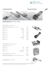
Lineartechnik Linear drives<br />
<strong>Lieferprogramm</strong> | <strong>product</strong> <strong>range</strong><br />
Linearführungen | linear guideways<br />
Allgemeine Informationen | general information A 1<br />
Serie | series HG & EG A 20<br />
Serie | series MG A 42<br />
Serie | series WE A 50<br />
Serie | series IG A 56<br />
Serie | series RG A 69<br />
Serie | series QH & QE A 84<br />
Serie | series Z A 92<br />
Positioniersysteme | positioning systems<br />
Linearmodule | linear module<br />
Serie | series KK A 98<br />
Serie | series KA A 113<br />
Serie | series KAS & KAR A 117<br />
Linearmotorachsen | linear motor axis A 126<br />
Rundtische & Torque-Motoren | rotary tables & torque motors A 128<br />
Elektrohubzylinder | linear actuators A 129<br />
Unsere Konstrukteure beraten Sie gerne bei der Realisierung Ihrer Anwendung - Fordern Sie uns heraus!<br />
We offer more than competitive prices - contact our engineering department!
Profilschienenführung - Allgemeine Informationen<br />
Linear Guideway - General Information<br />
Eigenschaften und Vorteile von Profilschienenführungen<br />
1. Hohe Positioniergenauigkeit<br />
Ein mit einer Profilschienenführung gelagerter Schlitten muss nur die<br />
Rollreibung überwinden. Der Unterschied zwischen der statischen<br />
und der dynamischen Rollreibung ist sehr gering, wodurch die Losbrechkraft<br />
nur geringfügig über der Bewegungskraft liegt. Es treten<br />
keine Stick-Slip-Effekte auf.<br />
2. Lange Lebensdauer bei besonders präziser Bewegung<br />
Bei einer Gleitführung können durch unterschiedliche Schmierfilmdicken<br />
Fehler in der Genauigkeit auftreten. Durch die Gleitreibung und<br />
oft auftretende Mangelschmierung entsteht ein hoher Verschleiß und<br />
damit eine abnehmende Genauigkeit. Im Gegensatz dazu hat die Profilschienenführung<br />
den Vorteil der sehr geringen Rollreibung verbunden<br />
mit extrem geringem Verschleiß. Die Führungsgenauigkeit bleibt über<br />
die gesamte Lebensdauer nahezu konstant.<br />
3. Große Geschwindigkeiten mit geringer Antriebskraft<br />
Durch den niedrigen Reibungskoeffizienten werden nur niedrige<br />
Antriebskräfte benötigt. Die erforderliche Antriebsleistung bleibt auch<br />
bei reversierenden Bewegungen gering.<br />
4. Gleich hohe Lastkapazität in alle Richtungen<br />
Durch die konstruktionsbedingte Zwangsführung kann eine Profilschienenführung<br />
Kräfte in vertikaler und horizontaler Richtung<br />
aufnehmen.<br />
5. Einfache Installation und Austauschbarkeit<br />
Die Montage einer Profilschienenführung ist einfach. Mit einer<br />
gefrästen oder geschliffenen Montagefläche wird bei Einhalten der<br />
Montageanweisungen eine hohe Genauigkeit erreicht. Herkömmliche<br />
Gleitführungen erfordern durch das Einschaben der Gleitflächen einen<br />
wesentlich höheren Montageaufwand. Das Austauschen einzelner<br />
Komponenten ist ohne Schaben nicht möglich. Profilschienenführungen<br />
können jedoch ohne weiteren Aufwand ausgetauscht werden.<br />
6. Unkomplizierte Schmierung<br />
Bei Gleitführungen führt eine unzureichende Schmierung zur Zerstörung<br />
der Gleitflächen. Das Schmiermittel muss an vielen Punkten den<br />
Gleitflächen zugeführt werden. Die Profilschienenführung benötigt nur<br />
eine Minimalmengenschmierung, die durch eine einfache Zuleitung<br />
zum Laufwagen hergestellt wird. Als Variante lieferbar ist auch ein<br />
Laufwagen mit austauschbarem Öltank (E2), was eine Langzeitschmierung<br />
gewährleistet.<br />
7. Rostschutz<br />
Zur Erzielung eines optimalen Rostschutzes werden Profilschienen<br />
und Laufwagen mit verschiedenen Beschichtungen geliefert:<br />
– Hicoat 1<br />
– Hicoat 2<br />
– Hicoat 3<br />
Die einzelnen Verfahren werden je nach Anwendungsfall gewählt.<br />
Für eine optimale Auswahl der Beschichtung werden die Daten der<br />
Umgebungsbedingungen und der korrosiven Stoffe benötigt. Die<br />
Miniatur-Profilschienenführungen (MG...) werden in rostfreiem Stahl<br />
gefertigt.<br />
A 1<br />
Advantages and features of linear guideways<br />
1. High positional accuracy<br />
When a load is driven by a linear motion guideway, the frictional contact<br />
between the load and the bed is rolling contact. The coefficient of friction<br />
is only 1 | 50th of traditional contact, and the difference between the<br />
dynamic and static coefficient of friction is small. Therefore, there would<br />
be no slippage while the load is moving.<br />
2. Long life with high motion accuracy<br />
With a traditional slide, errors in accuracy are caused by the counter<br />
flow of the oil film. Insufficient lubrication causes wear between the contact<br />
surfaces, which become increasingly inaccurate. In contrast, rolling<br />
contact has little wear; therefore, machines can achieve a long life with<br />
highly accurate motion.<br />
3. High speed motion is possible with a low driving force<br />
Because linear guideways have little friction resistance, only a small<br />
driving force is needed to move a load. This results in greater power<br />
savings, especially in the moving parts of a system. This is especially true<br />
for the reciprocating parts.<br />
4. Equal loading capacity in all directions<br />
With this special design, these linear guideways can take loads in either<br />
the vertical or horizontal directions.<br />
5. Easy installation and interchangeability<br />
Installing a linear guideway is fairly easy. Grinding or milling the machine<br />
surface, following a recommended installation procedure, and tightening<br />
the bolts to their specified torque can achieve highly accurate linear<br />
motion. Compared with traditional boxways or v-groove sliders, linear<br />
guideways can be easily replaced should any damage occur. For high<br />
precision grades consider ordering a matched, noninterchangeable,<br />
assembly of a block and rail.<br />
6. Easy lubrication<br />
With a traditional sliding system, insufficient lubrication causes wear<br />
on the contact surfaces. Also, it can be quite difficult to supply sufficient<br />
lubrication to the contact surfaces because finding an appropriate<br />
lubrication point is not very easy. With a linear motion guideway, grease<br />
can be easily supplied through the grease nipple on the linear guideway<br />
block. It is also possible to utilize a centralized oil lubrication system by<br />
piping the lubrication oil to the piping point.<br />
7. Anti-corrosive protection<br />
To realize optimal anti-corrosive protection, linear guideways and<br />
slides are available with diverse coatings:<br />
– Hicoat 1<br />
– Hicoat 2<br />
– Hicoat 3<br />
The choice of the method depends on the application. For an optimal<br />
choice of the coating, information about the environment conditions and<br />
the corrosive substances are needed. The miniature linear guideways<br />
are manufactured in stainless steel.
Profilschienenführung - Allgemeine Informationen<br />
Linear Guideway - General Information<br />
Auswahlprinzipien für eine Profilschienenführung<br />
a) Bestimmen Sie die Auswahlbedingungen<br />
- Maschinenbasis - Verfahrweg<br />
- max. Einbauraum - Verfahrgeschwindigkeit, Beschleunigung<br />
- gewünschte Genauigkeit - Nutzungsfrequenz<br />
- nötige Steifigkeit - Lebensdauer<br />
- Belastungsart - Umgebungsbedingungen<br />
b) Wählen Sie die Serie<br />
- HG Baureihe: Schleif-, Fräs-, Bohrmaschinen, Drehbänke,<br />
Bearbeitungszentren<br />
- EG Baureihe: Automationstechnik, Hochgeschwindigkeits-Transport,<br />
Halbleiterbestückung, Holzbearbeitung, Präzisions-Messgeräte<br />
- MGN/MGW Baureihe: Miniaturtechnik, Halbleiterbestückung,<br />
Medizintechnik<br />
c) Wählen Sie die Genauigkeitsklasse<br />
Klassen: C, H, P, SP, UP, abhängig von der erforderlichen Genauigkeit<br />
d) Legen Sie Größe und Zahl der Laufwagen fest<br />
Abhängig von Erfahrungswerten<br />
Abhängig von der Art der Belastung<br />
Wenn ein Kugelgewindetrieb eingesetzt wird, sollte die Nenngröße der<br />
Profilschienenführungen und des Kugelgewindetriebs ähnlich groß sein,<br />
z. B. 32er Kugelgewindetrieb und 35er Profilschiene.<br />
e) Berechnen Sie die maximale Last der Laufwagen<br />
Berechnen Sie die maximale Last anhand der Beispielrechnungen.<br />
Stellen Sie sicher, dass die statische Tragsicherheit der gewählten<br />
Profilschienenführung höher ist als der entsprechende Wert in der<br />
Tabelle zur statischen Tragsicherheit.<br />
f) Bestimmen Sie die Vorspannung<br />
Die Vorspannung hängt von den Anforderungen an die Steifigkeit und<br />
der Genauigkeit der Montagefläche ab.<br />
g) Bestimmen Sie die Steifigkeit<br />
Berechnen Sie die Verformung ( ∂ ) mit Hilfe der Steifigkeitstabelle;<br />
die Steifigkeit erhöht sich durch höhere Vorspannung und durch<br />
größere Maße der Führung.<br />
h) Berechnen Sie die Lebensdauer<br />
Ermitteln Sie die nötige Lebensdauer unter Berücksichtigung von<br />
Verfahrgeschwindigkeit und -frequenz; orientieren Sie sich an den<br />
Beispielrechnungen.<br />
i) Wählen Sie die Art der Schmierung<br />
Fettschmierung über Schmiernippel<br />
Ölschmierung über Anschlussleitung<br />
k) Auswahl beendet<br />
Selecting linear guideways<br />
a) Identify the condition<br />
- type of equipment - travel length<br />
- space limitations - moving speed, acceleration<br />
- accuracy - duty cycle<br />
- stiffness - service life<br />
- magnitude and directions of load - environment<br />
b) Selection of series<br />
- HG series: Grinding, milling, and drilling machine, lathe<br />
machine center<br />
- EG series: Automatic equipment, high speed transfer device,<br />
semiconductor equipment, wood cutting machine, precision<br />
measure equipment<br />
- MGN/MGW series: Miniature device, semiconductor equipment,<br />
medical equipment<br />
c) Selection of accuracy<br />
Classes: C, H, P, SP, UP depends on the accuracy of equipment<br />
d) Determine the size & the number of blocks<br />
Depends on experience value<br />
Dynamic load condition<br />
If accompanied with a ballscrew, the size should be similar to the<br />
diameter of ballscrew. For example, if the diameter of the ballscrew<br />
is 32 mm, then the model size of linear guideway should be HG35.<br />
e) Calculate the max. load of block<br />
Make reference to load calculation examples, and calculate the<br />
max. load. Be sure that the static safety factor of selected guideway<br />
is larger than the rated static safety factor<br />
f) Choosing preload<br />
Depends on the stiffness requirement and accuracy of<br />
mounting surface<br />
g) Identify stiffness<br />
Calculate the deformation ( ∂ ) by using the table of stiffness<br />
values, choosing heavier preload and larger size linear<br />
guideways to enhance the stiffness.<br />
h) Calculating service life<br />
Calculate the life time requirement by using the moving speed<br />
and frequency; make reference to the life calculation example<br />
i) Selection of lubrication<br />
Grease supplied by grease nipple<br />
Oil supplied by piping point<br />
k) Completion of selection<br />
A 2
Profilschienenführung - Allgemeine Informationen<br />
Linear Guideway - General Information<br />
Tragzahlen von Profilschienenführung<br />
1. Statische Tragzahl (C 0)<br />
Wenn eine Profilschienenführung während der Bewegung oder im<br />
Stillstand übermäßig hohen Lasten oder Schlägen ausgesetzt wird,<br />
entsteht eine lokale bleibende Verformung zwischen Laufbahn und<br />
Kugeln. Sobald diese bleibende Verformung ein bestimmtes Maß<br />
überschreitet, beeinträchtigt sie den leichtgängigen Betrieb der<br />
Führung. Die statische Tragzahl entspricht laut ihrer grundsätzlichen<br />
Definition einer statischen Last, die eine bleibende Verformung von<br />
0,0001x Kugeldurchmesser an dem Kontaktpunkt hervorruft, der<br />
am stärksten belastet wird. Die Werte werden in den Tabellen für<br />
jede Profilschienenführung angegeben. Anhand dieser Tabellen kann<br />
der Konstrukteur eine passende Profilschienenführung auswählen.<br />
Die maximale statische Last, der eine Profilschienenführung<br />
ausgesetzt wird, darf die statische Tragzahl nicht überschreiten.<br />
2. Zulässiges statisches Moment (M 0 )<br />
Das zulässige statische Moment ist das Moment, das in einer<br />
definierten Richtung und Größe der größtmöglichen Belastung der<br />
beweglichen Teile durch die statische Tragzahl entspricht. Das zulässige<br />
statische Moment ist für lineare Bewegungssysteme für drei<br />
Richtungen definiert: MX, MY und M0.<br />
3. Statische Tragsicherheit<br />
Für Profilschienen-Systeme in Ruhe und langsamer Bewegung muss<br />
die statische Tragsicherheit berücksichtigt werden, die von den<br />
Umgebungs- und Betriebsbedingungen abhängt. Eine erhöhte Tragsicherheit<br />
ist vor allem für Führungen wichtig, die Stoßbelastungen<br />
ausgesetzt werden (vgl. Tab. unten). Die statische Tragsicherheit kann<br />
nach folgender Formel berechnet werden.<br />
oder | or<br />
M 0<br />
Tabelle: Statische Tragsicherheit<br />
Belastung | load condition<br />
normale Belastung | normal load<br />
mit Stößen | Vibrationen | with impacts | vibrations<br />
4. Dynamische Tragzahl (C dyn)<br />
Die dynamische Tragzahl ist die in Richtung und Größe definierte Belastung,<br />
bei der eine Profilschienenführung eine nominelle Lebensdauer<br />
von 50 km Verfahrweg erreicht. Die dynamische Tragzahl ist für<br />
jede Führung in den Maßtabellen angegeben. Sie kann zur Berechnung<br />
der Lebensdauer einer bestimmten Führung benutzt werden.<br />
A 3<br />
M X<br />
Basic static load<br />
1. Static load rating (C 0)<br />
Localized permanent deformation will be caused between the<br />
raceway surface and the rolling elements when a linear guideway is<br />
subjected to an excessively large load or an impact load while either<br />
at rest or in motion. If the amount of this permanent deformation exceeds<br />
a certain limit, it becomes an obstacle to the smooth operation<br />
of the linear guideway. Generally, the definition of the basic static load<br />
rating is a static load of constant magnitude and direction resulting<br />
in a total permanent deformation of 0,0001 times the diameter of<br />
the rolling elements and the raceway at the contact point subjected<br />
to the largest stress. The value is described in the dimension tables<br />
for each<br />
linear guideway. A designer can select a suitable linear guideway by<br />
referring to these tables. The maximum static load applied to a linear<br />
guideway must not exceed the basic static load rating.<br />
2. Static permissible moment (M 0)<br />
The static permissible moment refers to a moment in a given direction<br />
and magnitude when the largest stress on the rolling elements in<br />
an applied system equals the stress induced by the static load rating.<br />
The static permissible moment in linear motion systems is defined for<br />
three directions: MX, MY and MO.<br />
M Y<br />
3. Static safety factor<br />
This condition applies when the guideway system is static or under<br />
low speed motion. The static safety factor, which depends on environmental<br />
and operating conditions, must be taken into consideration.<br />
A larger safety factor is especially important for guideways subject<br />
to impact loads (see table below). The static load can be obtained by<br />
using the following Eq.<br />
f SL = Statische Tragsicherheit für einfache Belastung | static safety factor for simple load<br />
f SM = Statisches Tragmoment | static safety factor for moment<br />
C 0 = Statische Tragzahl | static load rating [N]<br />
M 0 = zulässiges statisches Moment | static permissible moment [N/mm]<br />
P = Statisch äquivalente Traglast | calculated working load [N]<br />
M = Statisch äquivalentes Moment | calculated appling moment [N/mm]<br />
f SL , f SM [min.]<br />
1,0 - 3,0<br />
3,0 - 5,0<br />
Table: Static safety factor<br />
4. Dynamic load rating (C)<br />
The basic dynamic load rating is the load that does not change in<br />
direction or magnitude and results in a nominal life of 50 km of<br />
operation for a linear guideway. The values for the basic dynamic<br />
load rating of each guideway are shown in dimension tables. They<br />
can be used to predict the service life for a selected linear guideway.
Profilschienenführung - Allgemeine Informationen<br />
Linear Guideway - General Information<br />
Lebensdauer von Profilschienenführungen<br />
Definition der Lebensdauer<br />
Durch die ständige und wiederholte Belastung von Laufbahnen und<br />
Kugeln einer Profilschienenführung kommt es zu Ermüdungserscheinungen<br />
an der Laufbahnoberfläche. Am Ende kommt es zur<br />
sogenannten Pitting-Bildung. Die Lebensdauer einer Profilschienenführung<br />
ist definiert als der gesamte zurückgelegte Verfahrweg bis zum<br />
Auftreten der Pitting-Bildung an der Oberfläche der Laufbahn oder<br />
der Kugeln.<br />
Nominelle Lebensdauer (L)<br />
Die Lebensdauer kann selbst dann sehr unterschiedlich sein, wenn<br />
Profilschienenführungen auf die gleiche Weise hergestellt und unter<br />
den gleichen Bewegungsbedingungen eingesetzt werden. Daher wird<br />
die nominelle Lebensdauer als Richtwert für die Abschätzung der Lebensdauer<br />
einer Profilschienenführung angenommen. Die nominelle<br />
Lebensdauer entspricht dem gesamten Verfahrweg, den 90 % einer<br />
Gruppe von identischen und unter gleichen Bedingungen eingesetzten<br />
Profilschienenführungen ohne Ausfall erreichen. Bei Belastung mit<br />
der dynamischen Traglast beträgt die nominelle Lebensdauer 50 km.<br />
1. Berechnung der nominellen Lebensdauer<br />
Die tatsächliche Belastung beeinflusst die nominelle Lebensdauer<br />
einer Profilschienenführung. Mit Hilfe der ausgewählten dynamischen<br />
Tragzahl und der dynamisch äquivalenten Belastung kann die nominelle<br />
Lebensdauer anhand nachstehender Formel berechnet werden.<br />
L = Nominelle Lebensdauer | nominal life<br />
C dyn = C = Dynamische Tragzahl | basic dynamic load rating [N]<br />
P = Dynamisch äquivalente Belastung | actual load [N]<br />
Die Belastungsart, die Härte der Laufbahn und die Temperatur der<br />
Führung beeinflussen die nominelle Lebensdauer beträchtlich. Die<br />
Beziehung zwischen diesen Faktoren zeigt folgende Formel.<br />
L = Nominelle Lebensdauer | nominal life<br />
f h = Härtefaktor | hardness factor<br />
C dyn = C = Dynamische Tragzahl | basic dynamic load rating [N]<br />
f t = Temperaturfaktor | temperature factor<br />
P c = berechnete Last | calculated load [N]<br />
f w = Lastfaktor | load factor<br />
2. Faktoren der nominellen Lebensdauer<br />
Härtefaktor ( f h )<br />
Die Laufbahnen der Profilschienenführungen haben eine Härte von<br />
58 HRC. Dafür gilt ein Härtefaktor von 1,0. Bei einer abweichenden<br />
Härte ist der Härtefaktor nach nebenstehender Abbildung zu<br />
berücksichtigen. Wird die angegebene Härte nicht erreicht, reduziert<br />
sich die zulässige Belastung. In diesem Fall müssen die dynamische<br />
Tragzahl und die statische Tragzahl mit dem Härtefaktor multipliziert<br />
werden.<br />
Service life of linear guideways<br />
Service life<br />
When the raceway and the rolling elements of a linear guideway<br />
are continuously subjected to repeated stresses, the raceway surface<br />
shows fatigue. Flaking will eventually occur. This is called fatigue<br />
flaking. The life of a linear guideway is defined as the total distance<br />
traveled until fatigue flaking appears on the surface on the raceway<br />
or rolling elements.<br />
Nominal life (L)<br />
The service life varies greatly even when the linear motion guideways<br />
are manufactured in the same way or operated under the<br />
same motion conditions. For this reason, nominal life is used as<br />
the criteria for predicting the service life of a linear guideway. The<br />
nominal life is the total distance that 90% of a group of identical<br />
linear motion guideways, operated under identical conditions,<br />
can travel without flaking. When the basic dynamic rated load<br />
is applied to a linear motion guideway, the nominal life is 50 km.<br />
1. Calculation of nominal life<br />
The acting load will affect the nominal life of a linear guideway.<br />
Based in the selected basic dynamic rated load and the actual<br />
load, the nominal life can be calculated by using the following<br />
Eq.<br />
If the environmental factors are taken into consideration, the<br />
nominal life is influenced greatly by the motion condtions, the<br />
hardness of the raceway, and the temperature of the linear<br />
guideway. The relationship between these factors is expressed<br />
in the Eq. below.<br />
2. Factors of normal life<br />
Hardness factor ( f h )<br />
In general, the raceway suface in contact with the rolling elements<br />
must have the hardness of HRC 58, which corresponds to an<br />
hardness factor of 1,0. For deviate hardness the following figure<br />
must be taken into consideration. When the specified hardness<br />
is not obtained, the permissible load is reduced and the nominal<br />
life is decreased. In this situation, the basic dynamic load rating<br />
and the basic static load rating must be multiplied by the hardness<br />
factor for calculation.<br />
A 4
Profilschienenführung - Allgemeine Informationen<br />
Linear Guideway - General Information<br />
Temperaturfaktor ( f t )<br />
Wenn die Temperatur einer Profilschienenführung 100 °C überschreitet,<br />
reduziert sich die zulässige Last und die Lebensdauer.<br />
Daher müssen die dynamische Tragzahl und die statische Tragzahl<br />
mit dem Temperaturfaktor multipliziert werden..<br />
Lastfaktor ( f w )<br />
Zu den Lasten, die auf eine Profilschienenführung wirken, gehören<br />
das Gewicht des Laufwagens, die Trägheit zu Beginn und am Ende von<br />
Bewegungen, und Lastmomente, die durch Überstand der Last entstehen.<br />
Diese Lastfaktoren sind besonders dann schwer einzuschätzen,<br />
wenn Vibrationen oder Stoßbelastungen dazukommen. Daher<br />
sollte die Last mit dem empirischen Lastfaktor multipliziert werden.<br />
Tabelle: Lastfaktor<br />
Art der Belastung | loading condition<br />
keine Stöße und Vibrationen |no impacts & vibrations<br />
kleine Stöße | small impacts<br />
normale Last | normal load<br />
mit Stößen und Vibrationen | with impacts & vibrations<br />
Berechnung der Lebensdauer ( L h )<br />
Mit Hilfe der Verfahrgeschwindigkeit und Bewegungsfrequenz<br />
wird aus der nominellen Lebensdauer die Lebensdauer in Stunden<br />
berechnet.<br />
L h = Lebensdauer | service life [h]<br />
L = Nominelle Lebensdauer | nominal life [m]<br />
v = Geschwindigkeit | speed [m/min]<br />
C | P = Tragzahl/Last-Verhältnis | load faktor<br />
A 5<br />
Temperature factor ( f t )<br />
When the temperature factor of a linear guideway exceeds 100 °C,<br />
the permissible load is reduced and the nominal life is decreased.<br />
Therefore, the basic dynamic load rating and the basic static load<br />
rating must be multiplied by temperature factor.<br />
Load factor ( f w )<br />
The loads acting on a linear guideway include the weight of slide,<br />
the inertia load at the times of start and stop, and the moment<br />
loads caused by overhanging. These loads are especially difficult<br />
to estimate because of mechanical vibrations and impacts. Therefore,<br />
the load on a linear guideway should be divided by the empirical<br />
load factor.<br />
Verfahrgeschwindigkeit | service speed<br />
v < 15 m/min<br />
15 m/min < v < 60 m/min<br />
60 m/min < v < 120 m/min<br />
v > 120 m/min<br />
f w<br />
1,0 - 1,2<br />
1,2 - 1,5<br />
1,5 - 2,0<br />
2,0 - 3,5<br />
Calculation of service life ( L h )<br />
Transform the normal life into the service life time<br />
by using speed and frequency.<br />
Table: Load factor
Profilschienenführung - Allgemeine Informationen<br />
Linear Guideway - General Information<br />
Tabelle: Nomogramm zur Lebensdauer Table: alignment chart for service life<br />
Lebensdauer | service life (h)<br />
Eine Oberflächen-Schleifmaschine hat eine Arbeitslast von 20.000 N<br />
(5.000 N pro Laufwagen) und eine Verfahrgeschwindigkeit von 10 m/min.<br />
Wie hoch ist die Lebensdauer beim Einsatz von HGW30CC<br />
Profilschienenführungen?<br />
- Laut Maßtabelle auf Seite A 37 ist die dynamische Tragzahl des<br />
Modells HGW30CC 38.740 N, das Tragzahl/Last-Verhältnis ist also:<br />
- Berechnung der nominellen Lebensdauer<br />
- Die Linien des Tragzahl/Last-Verhältnisses und der Geschwindigkeit<br />
schneiden sich bei einem Lebensdauer-Wert von ca. 39.000 Stunden.<br />
- Lh kann auch durch Einsetzen der jeweiligen Werte in die<br />
entsprechende Formel (siehe Seite A 5) ermittelt werden.<br />
Bei einem zweischichtigen Betrieb beträgt die Lebensdauer<br />
rund 10 Jahre.<br />
Verfahrgeschwindigkeit | speed v (m/min)<br />
Tragzahl/Last- Verhältnis | load factor C/P<br />
A grinding machine has a work-load of 20.000 N<br />
(5.000 per slide) and a speed of 10 m/min.<br />
What is the service life, if HGW30CC linear guideways<br />
are used?<br />
- as shown in the table on page A 37, the dynamic load C of model<br />
HGW30CC is 38.740 N; therefore the load factor C/P is:<br />
- Calculation of the nominal life<br />
- The lines of load factor C/P and speed are intersecting<br />
at a service life value of about 39.000 hours.<br />
- Lh also can be calculated by inserting the relevant values<br />
into the Eq. on page A 5.<br />
With 2-shift duty, the service life is about 10 years.<br />
A 6
Profilschienenführung - Allgemeine Informationen<br />
Linear Guideway - General Information<br />
Betriebslast<br />
Berechnung der Last<br />
Bei der Berechnung der Lasten, die auf eine Profilschienenführung<br />
wirken, müssen verschiedene Faktoren berücksichtigt werden, z. B.<br />
der Schwerpunkt der Last, der Ansatz der Bewegungskraft und die<br />
Massenträgheit zu Beginn und am Ende der Bewegung. Um einen<br />
korrekten Wert zu erhalten, muss jeder Parameter berücksichtigt<br />
werden.<br />
1. Last auf einem Laufwagen<br />
Tabelle: Last auf einem Laufwagen<br />
(Beispiele für die Berechnung der Last auf einem Laufwagen)<br />
Typische Beispiele | patterns<br />
A 7<br />
Applied loads<br />
Calculation of load<br />
Several factors affect the calculation of loads acting on a linear guideway<br />
(such as the position of the object´s center of gravity, the thrust<br />
position, and the inertial forces at the time of start and stop). To<br />
obtain the correct load value, each load condition should be carefully<br />
considered.<br />
1. Load on one block<br />
Lastverteilung | loads layout<br />
Last auf den einzelnen Laufwagen | load on one block P1 ... P4<br />
Gewicht der Last | weight of the load W [N]<br />
Bewegungskraft; zusätzlich auftretende Kraft | driving force; additionally occuring force F [N]<br />
Kraft |<br />
force<br />
Kraft | force<br />
Kraft | force<br />
Kraft | force<br />
Table: Load on one block<br />
(Calculation example of loads on block)<br />
Last auf einem Laufwagen | load on the block
Profilschienenführung - Allgemeine Informationen<br />
Linear Guideway - General Information<br />
2. Last und Massenträgheit<br />
Tabelle: Last und Massenträgheit<br />
(Beispiele für die Berechnung von Last und Massenträgheit)<br />
Berücksichtigung der Beschleunigung und Abbremsung<br />
considering the acceleration and deceleration<br />
Bewegungsrichtung |movement<br />
Geschwindigkeit<br />
velocity<br />
(m/s)<br />
Zeit |times s<br />
Berechnung der äquivalenten Last bei veränderlichen Lasten<br />
Wenn die Belastung einer Profilschienenführung stark schwankt, muss<br />
eine äquivalente Last in die Berechnung der Lebensdauer eingehen. Die<br />
äquivalente Last ist definiert als die Last, die die gleiche Abnutzung an<br />
den Lagern bewirkt wie die veränderlichen Lasten. Sie kann mit Hilfe der<br />
folgenden Tabelle berechnet werden.<br />
Tabelle: Beispiele für die Berechnung der äquivalenten Last (Pm)<br />
Betriebsbedingungen<br />
operation condition<br />
2. Loads with inertia forces<br />
Table: Loads with inertia forces<br />
(Calculation examples for loads with inertia forces)<br />
konstante Geschwindigkeit |constant velocity<br />
Beschleunigung |acceleration<br />
Abbremsen |deceleration<br />
Last auf den einzelnen Laufwagen | load on one block P1 ... P4<br />
Bewegungskraft | driving force F [N]<br />
Gewicht der Last | weight of the load W [N]<br />
Erdbeschleunigung | gravitational acceleration g [9,8m/sec²]<br />
Geschwindigkeit | velocity v c [m/s]<br />
stufenweise Änderung | step load<br />
gleichförmige Änderung | linear variation<br />
sinusförmige Änderung | sinusoidal loading<br />
Last auf einem Laufwagen<br />
load on one block<br />
Calculation of the mean load for variable loading<br />
When the load on a linear guideway fluctuates greatly, the variable<br />
load condition must be considered in the life calculation. The definition<br />
of the mean load is the load equal to the bearing fatigue load under<br />
the variable loading conditions. It can be calculated by using the table<br />
below.<br />
äquivalente Last<br />
mean load<br />
Table: Calculation examples for mean load (P m )<br />
Pm äquivalente Last | mean load<br />
Pn veränderliche Last | stepping load<br />
L gesamter Verfahrweg | total running distance<br />
Ln Verfahrweg unter der Last Pn | running distance under load Pn P m äquivalente Last | mean load<br />
P min kleinste Last | min. load<br />
P max größte Last | max. load<br />
P m mittlere veränderliche Last | mean load<br />
P max größte veränderliche Last | max. load<br />
A 8
Profilschienenführung - Allgemeine Informationen<br />
Linear Guideway - General Information<br />
Reibungswiderstand<br />
Wie im Vorwort erwähnt, haben Profilschienenführungen durch den<br />
Einsatz von Kugeln eine Rollreibung. Der Reibungskoeffizient von Profilschienenführungen<br />
ist dadurch sehr klein, bis zu einem Fünfzigstel des<br />
Werts von traditionellen Gleitführungen. Im allgemeinen liegt der<br />
Reibungskoeffizient je nach Baureihe etwa bei 0,004.<br />
Wenn die Belastung nur 10 % oder weniger der dynamischen Tragzahl<br />
entspricht, entsteht der größte Teil des Reibungswiderstands durch die<br />
Abstreifer, sowie durch das Fett und die Reibung zwischen den Kugeln.<br />
Wird die Betriebslast größer als 10 % der dynamischen Tragzahl, sorgt<br />
die Last für den größten Teil des Reibungswiderstandes.<br />
Schmierung<br />
Profilschienenführungen müssen mit Fett oder Öl geschmiert werden.<br />
Dabei sind die Angaben der Schmierstoffhersteller einzuhalten. Die<br />
Mischbarkeit unterschiedlicher Schmierstoffe ist zu prüfen. Schmieröle<br />
auf Mineralölbasis sind bei gleicher Klassifikation (z.B. CL) und ähnlicher<br />
Viskosität (maximal eine Klasse Unterschied) mischbar. Fette sind<br />
mischbar, wenn ihre Grundölbasis und der Verdickungstyp gleich sind.<br />
Die Viskosität des Grundöls muss ähnlich sein. Die NGLI-Klasse darf sich<br />
um maximal eine Stufe unterscheiden. Nachdem die Schienenführung<br />
montiert ist, sollte eine Erstbefettung vorgenommen werden. Danach<br />
wird eine regelmäßige Schmierung empfohlen (siehe dazu die folgenden<br />
Tabellen). Über Schmieradapter kann der Laufwagen direkt an die<br />
Schmierleitung einer Zentralschmierung angeschlossen werden. Die<br />
Schmiernippel und Schmieradapter sind in den Kapiteln der jeweiligen<br />
Baureihe aufgeführt. Die benötigten Schmiermittelmengen für die<br />
Inbetriebnahme und die Nachschmierung werden ebenfalls in den<br />
folgenden Tabellen gezeigt. Sind die Profilschienenführungen senkrecht,<br />
zur Seite oder mit der Profilschiene nach oben eingebaut, werden die<br />
Nachschmiermengen um ca. 50 % erhöht.<br />
Schmieranweisung für Profilschienenführungen<br />
Profilschienenführungen benötigen wie jedes Wälzlager eine ausreichende<br />
Versorgung mit Schmierstoffen. Grundsätzlich ist sowohl eine<br />
Fett- als auch eine Ölschmierung möglich. Der Schmierstoff ist ein<br />
Konstruktionselement und sollte bereits beim Entwurf einer Maschine<br />
Berücksichtigung finden. Die Schmierstoffe verringern den Verschleiß,<br />
schützen vor Schmutz, behindern die Korrosion und verlängern durch<br />
ihre Eigenschaften die Gebrauchsdauer. Auf ungeschützten Profilschienen<br />
kann sich Schmutz ablagern und festsetzen. Diese Verunreinigungen<br />
müssen regelmäßig entfernt werden.<br />
1. Kurzhub-Anwendungen<br />
Bei Kurzhubanwendungen sind die Schmiermengen nach Tabelle 1 und<br />
3 zu verdoppeln.<br />
Hub < 2 x Wagenlänge: An beiden Seiten des Laufwagens Schmieranschlüsse<br />
vorsehen und schmieren.<br />
Hub < 0,5 x Wagenlänge: An beiden Seiten des Laufwagens Schmieranschlüsse<br />
vorsehen und schmieren. Dabei den Laufwagen mehrfach um<br />
2 Wagenlängen verfahren.<br />
Ist dies nicht möglich, bitten wir um Rückfrage.<br />
2. Grundschmierung bei Inbetriebnahme<br />
Profilschienenführungen werden konserviert geliefert. Die Erstbefettung<br />
erfolgt in drei Schritten:<br />
- Die Fettmenge nach Tabelle 1 zuführen<br />
- Den Laufwagen mehrmals um ca. drei Wagenlängen verfahren<br />
- Den beschriebenen Vorgang noch zwei Mal wiederholen<br />
A 9<br />
F = µ · W + S<br />
Reibungskraft |friction F [N]<br />
Reibungswiderstand | friction resistance S [N]<br />
Reibungskoeffizient | coefficient of friction µ<br />
Last | normal loads W [N]<br />
Friction<br />
As mentioned in the preface, a linear guideway allows a type of<br />
rolling motion, which is achieved by using balls. The coefficient<br />
of friction for a linear guideway can be as little as 1 | 50th of a<br />
traditional slide. Generally, the coefficient of friction of linear<br />
guideways is about 0,004.<br />
When a load is 10% or less than the basic static load rate, the most<br />
of the resistance comes from the grease viscosity and frictional<br />
resistance between balls. In contrast, if the load is more than the<br />
basic static load rating, the resistance will mainly come from<br />
the load.<br />
Lubrication<br />
Linear guideways must be lubricated with grease or oil. Please take<br />
note of the information of the lubricant producers. Check the miscibility<br />
of divers lubricants. Lube oils based on mineral oil with the<br />
same classification (e.g. CL) and similar viscosity (max. one class<br />
difference) are miscible. Greases are miscible if their basic oil types<br />
and thickner are equal. The viscosity of the basic oils must be similar.<br />
Maximum difference in the NGLI-classification is one class.<br />
After finishing the assembly of the linear guideways, a first lubrication is<br />
necessary. Afterwards, we recommend a continuous lubrication (see the<br />
following tables). By using a lubrication adapter, the slide can be connected<br />
to the pipe system of a central lubricating unit. The lubricating nipples<br />
and adapters for each series are scheduled in the respective catalogue<br />
chapter. The necessary lube quantities for the initial operation and while<br />
regular operating time is shown in the tables below. The necessary quantities<br />
of lube for the relubrication are 50% higher if the linear guideways<br />
are mounted vertical, sideways or with the rail above.<br />
Instruction: Lubrication of the guideways<br />
Like every antifriction bearing, linear guideways need a sufficient<br />
supply with lube. In general, both grease and oil lubrication is possible.<br />
The lube as an element of the whole construction should be taken into<br />
account as soon as possible, i.e. already while design. Lubricants reduce<br />
wear, protect from dirt, hinder corrosion and extend the service life with<br />
their attributes. On non-protected guideways can get soiled. This impurities<br />
must be removed in regular intervals.<br />
1. Application with short stroke<br />
At applications with short stroke, the lubricant quantities (table 1<br />
and 3) must be doubled.<br />
Stroke < 2 x length of slide: include lubricating adaptors on both<br />
sides of the slide. Common lubrication.<br />
Stroke < 0,5 x length of slide: include lubricating adaptors on both<br />
sides of the slide. Common lubrication. Move the slide along the<br />
distance of two times of a slides´ length.<br />
If not possible, please ask.<br />
2. Basic lubrication at initial operating<br />
Linear guideways are delivered conserved. Procedure of the initial<br />
lubrication:<br />
- supply with grease (quantity see table 1)<br />
- move the slide along the distance of three times of a slides´ length<br />
- repeat this procedure two times
Profilschienenführung - Allgemeine Informationen<br />
Linear Guideway - General Information<br />
3. Nachschmierung<br />
Die Nachschmierintervalle sind sehr stark von den Lasten und den<br />
Umgebungsbedingungen abhängig. Umgebungseinflüsse wie hohe<br />
Lasten, Vibrationen und Schmutz verkürzen die Nachschmierfristen.<br />
Bei sauberen Umgebungsbedingungen und geringen Lasten können<br />
die Nachschmierintervalle verlängert werden. Für normale Betriebsbedingungen<br />
gelten die Nachschmierfristen nach Tabelle 2.<br />
Fettschmierung<br />
Für eine Fettschmierung empfehlen wir Schmierfette<br />
nach DIN 51825:<br />
- Für normale Belastungen – K2K<br />
- Bei höheren Belastungen (C/ P < 15) – KP2K mit einer Konsistenzklasse<br />
NGLI 2 nach DIN 51818<br />
Die Hinweise der Schmierstoffhersteller sind zu beachten.<br />
1. Tabelle: Schmiermittelmengen<br />
Nenngröße |<br />
size<br />
2. Tabelle: Nachschmierintervall bei Fettschmierung<br />
Fettmenge bei Inbetriebnahme |<br />
lubricant quantity for initial operation<br />
[g]<br />
3. Relubrication<br />
The relubrication intervals strongly depend on the loads and environmental<br />
conditions. Environmental influences like high loads, vibrations<br />
and dirt shorten the relubrication intervals. An extension of the relubrication<br />
intervals is possible when low loads obtain and the environment is<br />
clean. For common running conditions, the relubrication intervals given in<br />
table 2 are valid.<br />
Grease lubrication<br />
For a lubrication with grease we suggest lubricants acc. to DIN 51825:<br />
- at common loads - K2K<br />
- at higher loads (C/P < 15) - KP2K with consistence class NGLI 2<br />
acc. to DIN 51818<br />
Please take note of the information of the lubricant producers.<br />
7/9 0,3 - 0,5 0,2<br />
12 0,5 - 0,8 0,4<br />
15 0,8 - 1,1 0,5<br />
20 1,1 - 1,4 0,6<br />
25 1,6 - 2,1 0,9<br />
30 2,4 - 3,0 1,3<br />
35 4,1 - 5,0 2,5<br />
45 5,6 - 6,5 3,0<br />
55 6,1 - 7,1 3,5<br />
65 8,0 - 9,0 4,1<br />
Nenngröße |<br />
size<br />
7 100<br />
9 120<br />
12 150<br />
15 1000<br />
20 1000<br />
25 1000<br />
30 900<br />
35 500<br />
45 250<br />
55 150<br />
65 140<br />
Nachschmierintervall [km] bei Belastung < 0,10 C dyn |<br />
relubrication intervals [km] at load < 0,10 C<br />
1. Table: Lubricant quantities<br />
Fettmenge zur Nachschmierung |<br />
lubricant quantity for relubrication<br />
[g]<br />
2. Table: relubrication intervals (lubrication with grease)<br />
3. Tabelle: Öl-Schmierung 3. Table: lubrication with oil<br />
Nenngröße |<br />
size<br />
Erst- und Nachschmierung (cm³) |<br />
initial lubrication and relubrication (cm³)<br />
7 0,2<br />
9 0,2<br />
12 0,3<br />
15 0,5<br />
20 0,8<br />
25 0,9<br />
30 1,2<br />
35 1,3<br />
45 2,5<br />
55 4,0<br />
65 6,5<br />
A 10
Profilschienenführung - Allgemeine Informationen<br />
Linear Guideway - General Information<br />
Ölschmierung<br />
Die Mengen zu Erst- und Nachschmierung sind in Tabelle 3 aufgeführt.<br />
Die Mengen sind mit einem Impuls zuzuführen.<br />
1. Öl-Zentralschmierung<br />
Bei Zentralschmieranlagen kann die Ölmenge häufig nicht in einem<br />
Impuls zugeführt werden. Die Mengen nach Tabelle 3 können dann in<br />
mehreren Teilmengen zugeführt werden. Zwischen den einzelnen Impulsen<br />
sollte eine Wartezeit von 10–20 Sekunden eingehalten werden.<br />
2. Kurzhub<br />
Für Kurzhubanwendungen gelten die Angaben wie bei der Fettschmierung.<br />
Selbstschmierende E2-Laufwagen<br />
Der selbstschmierende E2-Laufwagen besteht aus einer Schmiereinheit<br />
zwischen Umlenksystem und Abschlussdichtung und einem austauschbaren<br />
Öltank. Zum Austausch des Öltanks ist eine Demontage des<br />
Laufwagens nicht erforderlich. Der Schmierstoff gelangt vom Öltank<br />
über das Anschlussstück zur Schmiereinheit, die dann die Laufbahn der<br />
Profilschiene schmiert. Durch den speziellen Aufbau des Öltanks kann<br />
der Laufwagen in jeder beliebigen Position montiert werden, ohne dass<br />
die Schmierwirkung beeinflusst wird.<br />
Anwendungen<br />
- Werkzeugmaschinen<br />
- Produktionsmaschinen: Spritzgußmaschinen, Papierindustrie, Textilmaschinen,<br />
Lebensmittelindustrie, Holzbearbeitungsmaschinen<br />
- Elektronikindustrie: Halbleiterindustrie, Robotertechnik, Kreuztische,<br />
Mess- und Prüfmaschinen<br />
- Andere Bereiche: Medizinische Ausrüstung, Automatisierung,<br />
Handhabungstechnik<br />
Schmiereinheit | lubrication unit<br />
A 11<br />
Schiene | rail<br />
Schmierlippe<br />
lubrication lip<br />
Austauschbarer Öltank | exchangeable oil tank<br />
Lubrication with oil<br />
The quantities for initial lubrication and relubrication are shown<br />
in table 3. The quantities should be supplied in one impulse.<br />
1. Central oil lubrication<br />
When central lubrication systems are used, the quantity of oil can<br />
not be supplied in one impulse. Then, the quantities (table 3) can<br />
be supplied in subsets. Between the impulses, keep a waiting time<br />
of 10 - 20 seconds.<br />
2. Short stroke<br />
No difference to grease lubrication.<br />
Self-lubricating E2-slides<br />
The self-lubricating E2-slide consists of a lubricating unit between<br />
reversing system and closing seal and an exchangeable oil tank.<br />
In the case of an exchange of the oil tank, an dismantling of the<br />
slide is not necessary. Way of the lubricant: from the oil tank<br />
through the connecting piece to the lubrication unit, which<br />
lubricates the running surface of the guideway.<br />
The design of the oil tanks allows an assembly of the slide in any<br />
position, without affecting the lubricating effect.<br />
Application:<br />
- machine tools<br />
- <strong>product</strong>ion machines: injection molding machines, paper<br />
industry, textile machines, food industry, wood processing machines<br />
- electronic industry: semiconductor industry, robotics, X-Y benches,<br />
measuring technology<br />
- other: medical technology, automation, handling technology<br />
Tabelle: Maßtabelle HG, EG mit E2-Schmierung Table: Dimensions HG, EG with E2-Lubrication<br />
Modell |<br />
model<br />
Abmessungen des Laufwagens |<br />
dimensions of the slide<br />
Modell |<br />
model<br />
Abmessungen des Laufwagens |<br />
dimensions of the slide<br />
W H T V L W H T V L<br />
HG 15 C<br />
HG 20 C<br />
HG 20 H<br />
HG 25 C<br />
HG 25 H<br />
HG 30 C<br />
HG 30 H<br />
HG 35 C<br />
HG 35 H<br />
32,4<br />
43<br />
46,4<br />
58<br />
68<br />
19,5<br />
24,4<br />
29,5<br />
35<br />
38,5<br />
12,5<br />
13,5<br />
13,5<br />
13,5<br />
13,5<br />
3<br />
3,5<br />
3,5<br />
3,5<br />
3,5<br />
75,4<br />
93,6<br />
108,3<br />
100,5<br />
121,1<br />
112,9<br />
135,9<br />
127,9<br />
153,7<br />
EG 15 S<br />
EG 15 C<br />
EG 20 S<br />
EG 20 C<br />
EG 25 S<br />
EG 25 C<br />
EG 30 S<br />
EG 30 C<br />
33,3<br />
41,3<br />
47,3<br />
59,3<br />
18,7<br />
20,9<br />
24,9<br />
31<br />
11,5<br />
13<br />
13<br />
13<br />
3<br />
3<br />
3<br />
3<br />
55,2<br />
71,9<br />
66,6<br />
85,7<br />
77,1<br />
100,6<br />
87,5<br />
116,1<br />
HG 45 C<br />
HG 45 H<br />
82 49 16 4,5<br />
157,2<br />
189,0<br />
HG 55 C<br />
HG 55 H<br />
97 55,5 16 4,5<br />
183,9<br />
222,0<br />
HG 65 C<br />
HG 65 H<br />
121 69 16 4,5<br />
219,7<br />
279,1
Profilschienenführung - Allgemeine Informationen<br />
Linear Guideway - General Information<br />
Standardöl:<br />
Mobil SHC 636, vollsynthetisch auf Hydrocarbon-Basis (PAO)<br />
Viskositätsklasse: ISO VG 680<br />
Ersatzweise können Öle gleicher Klassifikation und Viskosität<br />
verwendet werden.<br />
Die Austauschintervalle sind sehr stark von den Lasten und den Umgebungsbedingungen<br />
abhängig. Umgebungseinflüsse wie hohe Lasten,<br />
Vibrationen und Schmutz verkürzen die Austauschintervalle.<br />
Die folgende Tabelle gibt an, wann der Füllstand des Öltanks spätestens<br />
überprüft werden soll.<br />
Angesetzte Profilschienen<br />
Angesetzte Profilschienenführungen müssen gemäß dem Pfeil und<br />
der laufenden Nummer montiert werden, die auf der Oberfläche jeder<br />
Profilschiene angebracht sind. Bei paarweise montierten Profilschienen<br />
sollten die Stoßfugen versetzt werden (siehe Bild unten).<br />
Standard oil:<br />
Mobil SHC 636, full synthetic, based on hydrocarbon (PAO)<br />
Viscosity class: ISO VG 680<br />
Substed, oils of the same classification and viscosity can be used.<br />
The exchange intervals strongly depend on the loads and environmental<br />
conditions. Environmental influences like high loads, vibrations and dirt<br />
shorten the exchange intervals. The following table shows, until the fill<br />
level of the oil tank at last should be checked.<br />
Tabelle: Schmiermittelmengen Table: Lubrication quantities<br />
Modell |<br />
model<br />
Ölmenge |<br />
oil quantity [cm³]<br />
Jointed rail<br />
Laufleistung |<br />
running distance [km]<br />
HG15E2 1,6 1000<br />
HG20E2 3,9 2000<br />
HG25E2 5,1 3000<br />
HG30E2 7,3 4000<br />
HG35E2 9,8 5000<br />
HG45E2 18,5 10000<br />
HG55E2 25,9 15000<br />
HG65E2 50,8 25000<br />
EG15E2 1,7 1000<br />
EG20E2 2,9 1500<br />
EG25E2 4,8 2500<br />
EG30E2 8,9 4500<br />
1 Öltank | oil tank<br />
2 Schmiereinheit | lubrication unit<br />
3 Anschlussstück | connecting piece<br />
4 Schraube | screw<br />
5 Abschlussdichtung | closing seal<br />
6 Verschlussschraube | screw plug<br />
7 Umlenksystem | reversing system<br />
Jointed rail should be installed by following the arrow sign and ordinal<br />
number which is marked on the surface of each rail. For matched pair,<br />
jointed rail, the jointed positions should be staggered. This will avoid accuracy<br />
problems due to discrepancies between the 2 rails (see figure).<br />
A 12
Profilschienenführung - Allgemeine Informationen<br />
Linear Guideway - General Information<br />
Montage<br />
Eine Profilschienenführung kann Lasten nach rechts/links und oben/<br />
unten aufnehmen. Die Einbaulage hängt von den Erfordernissen der<br />
Maschine und der Belastungsrichtung ab. Die Genauigkeit der Profilschiene<br />
wird durch die Geradheit und Ebenheit der Anlageflächen<br />
bestimmt, da die Profilschiene beim Anziehen der Schrauben an diese<br />
he<strong>range</strong>zogen wird. Profilschienen, die nicht an einer Anlagefläche<br />
angeschlagen werden, können größere Toleranzen in der Geradheit<br />
aufweisen. Im folgenden sind die typischen Einbausituationen dargestellt:<br />
A 13<br />
Mounting configurations<br />
A linear guideway can carry loads in right / left and up / down direction.<br />
The fitting position depends on the machine requirements and load<br />
directions. The straightness and evenness of the installation surface determines<br />
the accuracy of the linear guideway, because when tightening<br />
the screws, the linear guideway is pulled up to it. Linear guideways, which<br />
are not mounted on a installation surface can show a lower accuracy.<br />
Typical layouts for linear guideways are shown below:
Profilschienenführung - Allgemeine Informationen<br />
Linear Guideway - General Information<br />
Einbau von Profilschienenführungen<br />
Steifigkeit und Präzision für Maschinen mit Vibrationen und Stößen<br />
1. Befestigungsarten<br />
Wenn die Maschine Vibrationen und Stößen oder Seitenkräften ausgesetzt<br />
ist, können sich Führungen und Laufwagen verschieben. Um<br />
dieses Problem zu umgehen und eine hohe Führungsgenauigkeit zu<br />
erreichen, werden die folgenden vier Befestigungsarten empfohlen.<br />
2. Vorgehen bei der Montage der Führungen<br />
Mounting procedures<br />
Rigidity and accuracy of machines with vibrations and impacts<br />
1. Mounting methods<br />
It is possible that the rails and the blocks will be displaced when the<br />
machine is subjected to vibrations and impacts. To eliminate these<br />
difficulties and achieve high running accuracy, the following four<br />
methods are recommended for fixing.<br />
2. Procedure of rail installation<br />
A 14
Profilschienenführung - Allgemeine Informationen<br />
Linear Guideway - General Information<br />
a) Vor Beginn alle Verschmutzungen von der<br />
Oberfläche der Maschine entfernen.<br />
b) Profilschiene vorsichtig auf das Bett legen<br />
und fest an der Anschlagkante anlegen.<br />
c) Bei der Ausrichtung der Profilschiene auf<br />
dem Bett prüfen, ob die Gewinde der ein-<br />
gesetzten Schrauben greifen.<br />
d) Klemmschrauben nacheinander anziehen, um<br />
guten Kontakt zwischen der Profilschiene<br />
und der Anschlagkante sicherzustellen.<br />
e) Schienen-Befestigungsschrauben mit einem<br />
Drehmomentschlüssel in drei Stufen bis zu<br />
dem angegebenen Drehmoment anziehen.<br />
f) Die zweite Profilschiene in der gleichen Weise<br />
montieren.<br />
3. Vorgehen bei der Montage des Laufwagens<br />
a) Schlitten vorsichtig auf den Laufwagen legen.<br />
Dann Schlitten-Befestigungsschrauben vorläufig<br />
anziehen.<br />
b) Laufwagen gegen die Anschlagkante des<br />
Schlittens drücken und den Schlitten durch An-<br />
ziehen der Klemmschrauben ausrichten.<br />
c) Um den Schlitten gleichmäßig fest zu montieren,<br />
die Befestigungsschrauben auf der Referenzseite<br />
und der Folgeseite in vier Durchgängen anziehen.<br />
A 15<br />
Ölstein |<br />
oil stone<br />
a) Before starting, remove all dirt from the<br />
mounting surface of the machine.<br />
b) Place the linear guideway gently on the bed.<br />
Bring the guideway into close contact<br />
with the datum plane of the bed.<br />
c) Check for correct thread engagement<br />
when inserting a bolt into the mounting<br />
hole while the rail is being placed on<br />
the mounting surface of the bed.<br />
d) Tighten the push screws sequentially<br />
to ensure close contact between the<br />
rail and the side datum plane.<br />
e) Tighten the mounting bolts with a<br />
torque wrench to the specified torque.<br />
f) Install the remaining linear guideway<br />
in the same way.<br />
3. Procedure of block installation<br />
a) Place the table gently on the blocks.<br />
Next, tighten the block mounting<br />
bolts temporarily.<br />
b) Push the blocks against the datum plane<br />
of the table and position the table by<br />
tightening the push screws.<br />
c) The table can be fixed uniformly by<br />
tightening the mounting bolts on<br />
master guide side and subsidiary<br />
side in 1 to 4 sequences.
Profilschienenführung - Allgemeine Informationen<br />
Linear Guideway - General Information<br />
Montagebeispiel für eine Referenzführung ohne Klemmschrauben<br />
Um die Parallelität zwischen Referenz- und Folgeschiene ohne<br />
Klemmschrauben zu gewährleisten, werden die folgenden<br />
Methoden für die Montage empfohlen. Die Installation des<br />
Laufwagens bleibt wie zuvor beschrieben.<br />
1. Montage der Führung auf der Referenzseite<br />
Mit Hilfe einer Schraubzwinge:<br />
Legen Sie die Führung auf die Montagefläche des<br />
Maschinenbetts. Die Befestigungsschrauben<br />
leicht anziehen und dann die Führung mit Hilfe einer<br />
Schraubzwinge gegen die Anschlagkante des<br />
Maschinenbetts drücken. Anschließend die<br />
Befestigungsschrauben nacheinander mit dem<br />
angegebenen Drehmoment festziehen.<br />
2. Montage der Führung auf der Folgeseite<br />
Ausrichten an einem Lineal:<br />
Legen Sie das Lineal zwischen die Führungen und<br />
richten Sie es mit Hilfe einer Messuhr parallel zur<br />
Anschlagkante auf der Referenzseite aus. Wenn<br />
die Führung auf der Folgeseite parallel zur Referenzseite<br />
ausgerichtet ist, die Befestigungsschrauben<br />
nacheinander von einem zum anderen Ende<br />
der Führung festziehen.<br />
Mit Hilfe eines Schlittens:<br />
Montieren Sie eine Platte auf zwei Laufwagen auf<br />
der Referenzschiene. Auf der Folgeseite die Schiene<br />
auf dem Maschinenbett und einen Laufwagen am<br />
Schlitten lose befestigen. Dann eine Messuhr auf<br />
dem Schlitten anbringen und den Messfühler an die<br />
Seite des Laufwagens der Folgeschiene anlegen.<br />
Den Schlitten anschließend von einem zum anderen<br />
Ende bewegen und die Folgeschiene parallel zur<br />
Referenzschiene ausrichten. Dann nacheinander<br />
die Befestigungsschrauben anziehen.<br />
Installation of the master guide without push screws<br />
To ensure parallelism between the subsidiary guide and the master<br />
guide without push screws, the following rail installation methods are recommended.<br />
The block installation is the same as mentioned previously.<br />
1. Installation of the rail on the subsidiary side<br />
Using a vice:<br />
Place the rail into the mounting plane of the<br />
bed. Tighten the mounting bolts temporarily;<br />
then use a vice to push the rail against the<br />
side datum plane of the bed. Tighten the<br />
mounting bolts in sequence to the<br />
specified torque.<br />
2. Installation of the rail on the subsidiary guide side<br />
Method with use of a straight edge:<br />
Set a straight edge between the rails parallel to<br />
the side datum plane of the rail on the master<br />
guide side by using a dial gauge. Use the dial<br />
gauge to obtain the straight alignment of the<br />
rail on the subsidiary guide side. When the rail<br />
on the subsidiary guide side is parallel to the<br />
master side, tighten the mounting bolts in<br />
sequence from one end of the rail to the other.<br />
Method with use of a table:<br />
Fix two blocks on the master guide side<br />
to the table. Temporarily fix the rail and<br />
one block on the subsidiary guide side<br />
to the bed and the table. Fix a dial<br />
gauge stand on the table surface and<br />
bring it into contact with the side of<br />
the block on the the subsidiary guide<br />
side. Move the table from one end to<br />
the other. While aligning the rail on<br />
the subsidiary side parallel to the rail<br />
on the master guide side, tighten the<br />
bolts in sequence.<br />
A 16
Profilschienenführung - Allgemeine Informationen<br />
Linear Guideway - General Information<br />
Ausrichten an der Referenzschiene:<br />
Wenn die Referenzschiene korrekt installiert ist,<br />
montieren Sie eine Platte fest auf zwei Laufwagen<br />
auf der Referenzschiene und einen der beiden Laufwagen<br />
auf der Folgeschiene. Dann den Schlitten<br />
von einem Ende der Schienen zum anderen<br />
bewegen und dabei die Befestigungsschrauben<br />
der Folgeschiene festziehen.<br />
Mit Hilfe einer Lehre:<br />
Legen Sie die die Position der Folgeschiene mit<br />
Hilfe einer speziellen Lehre fest und ziehen Sie<br />
die Befestigungsschrauben mit dem angegebenen<br />
Drehmoment fest.<br />
Montage von Referenzführungen ohne Anschlagkante<br />
Um die Parallelität von Referenz- und Folgeschiene auch ohne Anschlagkante<br />
auf der Referenzseite zu gewährleisten, wird die folgende<br />
Art der Montage empfohlen. Die Montage der Laufwagen bleibt wie<br />
zuvor beschrieben.<br />
1. Montage der Referenzschiene<br />
Ausrichten an einer provisorischen Anschlagkante:<br />
Zwei Laufwagen eng beieinander mit einer Platte verbinden.<br />
Zur Ausrichtung der Schiene von einem zum anderen Ende<br />
eine Kante am Maschinenbett benutzen. Laufwagen zur<br />
Prüfung bewegen und die Befestigungsschrauben nacheinander<br />
mit dem angegebenen Drehmoment festziehen.<br />
Ausrichten an einem Lineal:<br />
Richten Sie die Schiene von einem Ende zum anderen<br />
mit Hilfe einer Messuhr an einem Lineal aus. Achten Sie<br />
darauf, die Befestigungsschrauben nacheinander fest<br />
anzuziehen.<br />
2. Montage der Folgeschiene<br />
Die Montage der Folgeschiene entspricht dem Ablauf einer Montage<br />
ohne Klemmschraube<br />
A 17<br />
Method following the master guide side:<br />
When a rail on the master guide side is correctly<br />
tightened, fix both blocks on the master guide<br />
side and one of the two blocks on the subsidiary<br />
guide side completely to the table.<br />
When moving the table from one end of the<br />
rail, tighten the mounting bolts on the subsidiary<br />
guide side completely.<br />
Method with use of a jig:<br />
Use a special jig to ensure the rail position<br />
on the subsidiary guide side. Tighten the<br />
mounting bolts to the specified torque<br />
in sequence.<br />
When there is no side surface of the bed on the master guide side<br />
To ensure parallelism between the subsidiary guide and the master<br />
guide when there is no side surface, the following rail installation<br />
method is recommended. The installation of the blocks is the same<br />
as mentioned previously.<br />
1. Installation on the rail on the master guide side<br />
Using a provisional datum plane:<br />
Two blocks are fixed in close contact by the measuring<br />
plate. A datum plane provided on the bed is used<br />
for straight alignment of the rail from one end to the<br />
other. Move the blocks and tighten the mounting<br />
bolts to the specified torque in sequence.<br />
Method with use of a straight edge:<br />
Use a dial gauge and a straight edge to confirm the<br />
straightness of the side datum plane of the rail from<br />
one end to the other. Make sure the mounting bolts<br />
are tightened securely in sequence.<br />
2. Installation of the rail on the subsidiary guide side<br />
The method of installation is the same as the case without push<br />
screws.
Profilschienenführung - Allgemeine Informationen<br />
Linear Guideway - General Information<br />
Zulässige Montageabweichungen<br />
Montageabweichungen beeinträchtigen die Lebensdauer von Profilschienenführungen.<br />
Die in untenstehender Tabelle wiedergegebenen<br />
maximalen Abweichungen gewährleisten bei einer Belastung von 0,1<br />
Cdyn eine Lebensdauer von 5.000 km. Die Parallelitätsabweichung<br />
von zwei Schienen darf über den gesamten Verfahrweg bzul nicht<br />
überschreiten. Die zulässige Höhenabweichung entspricht einem<br />
Verkippungswinkel. Der Verkippungswinkel bezieht sich auf einen<br />
Schienenabstand von 200 mm. Bei einem anderen Schienenabstand<br />
ist der Wert hzul nach folgender Formel zu berechnen. Für die Höhenabweichung<br />
zweier Wagen auf einer Schiene sind 0,2 hzul zulässig.<br />
Bei einer weichen Schlittenkonstruktion kann dieser Wert bis maximal<br />
0,4 hzul erweitert werden.<br />
h zul = h ·<br />
Inbetriebnahme<br />
Vor der Inbetriebnahme sind die Profilschienenführungen zu befetten.<br />
Gegen feste und flüssige Verunreinigungen ist ein Schutz vorzusehen.<br />
Die Laufwagen sind vor dem Einbau mit der Fettmenge für die Inbetriebnahme<br />
zu befetten (siehe Tabelle 1 Seite A 10). Ist die Profilschiene<br />
an eine Zentralschmieranlage angeschlossen, kann mit ihr die<br />
Erstbefettung durchgeführt werden. Es ist sicherzustellen, dass die<br />
Schmierleitungen gefüllt sind. Eine gleichmäßige Verteilung des Fettes<br />
im Laufwagen wird durch wiederholtes Bewegen des Laufwagens<br />
um ca. 5 Wagenlängen erreicht. Wenn eine Profilschienenführung<br />
nicht über den Laufwagen nachgeschmiert werden kann, muss der<br />
Schmierstoff auf die Profilschiene aufgebracht werden.<br />
Reinigung<br />
Zur Reinigung von Profilschienenführungen sollte dünnes Öl oder<br />
Waschbenzin verwendet werden. Lacklösemittel oder Kaltreiniger<br />
können Beschädigungen verursachen.<br />
Lagerfähigkeit<br />
Die verwendeten Schmierstoffe sind ca. drei Jahre lagerfähig.<br />
Bei langer Lagerung kann das Reibmoment anfänglich höher sein<br />
als bei frisch abgeschmierten Laufwagen. Durch die Lagerung<br />
verringert sich die Qualität des Schmierstoffes. Die Angaben der<br />
Schmierstoffhersteller sind zu berücksichtigen. Der Lagerort soll ein<br />
geschlossener Raum bei Temperaturen von 0 °C bis +40 °C sein.<br />
Die relative Luftfeuchtigkeit soll unter 70 % liegen. Einwirkungen<br />
durch Kondenswasser, schädliche Gase oder Flüssigkeiten müssen<br />
verhindert werden.<br />
Schienenabstand | rail distance<br />
Tabelle: Zulässige Montagetoleranzen Table: Permissible mounting deviation<br />
Toleranz | tolerance Vorspannungsklasse |<br />
pre-load class<br />
Permissible mounting deviation<br />
200<br />
Baureihe | series<br />
Größe | size<br />
MGN/MGW HG/EG<br />
Mounting deviations affect the service life of linear guideways.<br />
With the maximum deviation values shown in the table below and a<br />
load of 0,1 C, a service life of 5.000 km is guaranteed. Parallelism<br />
deviation of two rails must not be higher than bzul during the whole<br />
running distance. The permissible height deviation corresponds to a<br />
dumping angle. The dumping angle is related to a rail distance of 200<br />
mm. For other distances, please use the formula below to calculate<br />
hzul. For the height deviation of two slides on one rail, 0,2 hzul are<br />
permissible.<br />
In the case of a smoother slide construction, this value can be extended<br />
to a maximum of 0,4 hzul.<br />
[µm] 7 9 12 15 15 20 25 30 35 45 55 65<br />
b zul<br />
max. Parallelitäts- Z0 4 5 9 10 20 25 25 25 30 40 45 50<br />
abweichung von Z1 3 3 5 6 - - - - - - - -<br />
zwei Schienen ZA - - - - 15 20 20 20 25 30 35 40<br />
max. parallelism ZB - - - - 15 15 10 15 15 20 25 30<br />
deviation of two rails<br />
h<br />
max. Höhenabweichung Z0 25 35 50 60 75 µm<br />
von zwei Schienen Z1 6 10 15 30 -<br />
max. height deviation ZA/ZB - - - - 50 µm<br />
of two rails<br />
Initial operation<br />
Before starting the initial operation, the linear guideways must be<br />
lubricated. A protection against firm and fluid dirt should be installed.<br />
Before mounting, the slides must be lubricated with the necessary<br />
quantity of grease (see table 1 on page A 10). If the linear guideway is<br />
connected to a central lubrication system, it can be used for the first<br />
lubrication. Check the filling level of the lubrication pipelines. Repeated<br />
movement of the slide along a running distance of five times of a<br />
slides´ lenght achieves a constant allocation of the grease. If lubrication<br />
of the linear guideway with the slide is not possible the lubricant<br />
must be put on the rail.<br />
Cleaning<br />
Use very fluid oil or benzine to clean the linear guideways.<br />
Lacquer solvents or cleaner solvents can damage the guideways.<br />
Shelf life<br />
The used lubricants are storable for 3 years. After long storage, the<br />
friction moment initially can be higher than when a recent lubricated<br />
slide is used. Storage reduces the quality of the lubricant. Information<br />
of lubricant producers should be considered. Suitable for storage<br />
is a closed room; temperature <strong>range</strong> 0 °C to +40 °C.<br />
The relative humidity should be less than 70 %.<br />
Prevent impacts of condensate, injurious gases and fluids.<br />
A 18
Profilschienenführung - Allgemeine Informationen<br />
Linear Guideway - General Information<br />
Profilschienenführung: Baureihen<br />
Für die verschiedenen Kunden-Bedürfnisse wurden unterschiedliche<br />
Produktbaureihen entwickelt: Die HG-Baureihe für Werkzeugmaschinen,<br />
die hohe Steifigkeit und Genauigkeit benötigen, die niedrig<br />
bauende EG-Baureihe für die Automatisierungstechnik und die<br />
Miniatur-Baureihe MGN/MGW.<br />
1. Modelle und Baureihen<br />
Tabelle: Modelle und Baureihen<br />
Baureihe |<br />
series<br />
Tabelle: Genauigkeitsklassen<br />
Tabelle: Vorspannungsklassen<br />
A 19<br />
Montagehöhe |<br />
assembly height<br />
Lastklasse |<br />
load<br />
Linear guideway <strong>product</strong> series<br />
To satisfy various needs of customers, numerous <strong>product</strong>s has been<br />
developed. HG series is a heavy load ball-type for machine tools which<br />
requires high accuracy and rigidity; the EG series is a low-profile<br />
guideway for the automation industry which requires high speed and<br />
smooth motion; and the MGN/MGW series is a miniature type<br />
for semiconductor equipment and other miniature equipment.<br />
1. Types and Series<br />
Hohe Ausführung |<br />
square<br />
Table: Types and Series<br />
Flanschausführung<br />
| flange<br />
HG hoch | high Schwerlast | heavy load HGH-CA -<br />
Super-Schwerlast | super heavy load HGH-HA -<br />
niedrig | low Schwerlast | heavy load - HGW-CC<br />
Super-Schwerlast | super heavy load - HGW-HC<br />
EG niedrig | low mittlere Last | medium load EGH-SA EGW-SC<br />
Schwerlast | heavy load EGH-CA EGW-CC<br />
MGN - Standard | standard MGN-C -<br />
Schwerlast | heavy load MGN-H -<br />
MGW - Standard | standard MGW-C -<br />
Schwerlast | heavy load MGW-H -<br />
2. Genauigkeitsklassen<br />
Baureihe |<br />
series<br />
nicht-austauschbare Modelle<br />
non-interchangeable type<br />
Normal |<br />
normal<br />
(C)<br />
nicht-austauschbare Modelle<br />
non-interchangeable type<br />
austauschbare Modelle<br />
interchangeable type<br />
austauschbare Modelle<br />
interchangeable type<br />
Table: Accuracy classes<br />
HG � � � � � � � �<br />
EG � � � � � � � �<br />
MGN � � � - - � � �<br />
MGW � � � - - - - -<br />
3. Vorspannungsklassen<br />
Genauigkeitsklasse |<br />
accuracy class<br />
Baureihe |<br />
series<br />
Hoch |<br />
high<br />
(H)<br />
C-UP<br />
spielfrei<br />
free from play<br />
Präzision |<br />
precision<br />
(P)<br />
C-UP<br />
leicht vorgespannt |<br />
light preload<br />
Super-Präzision |<br />
super precision<br />
(SP)<br />
2. Accuracy classes<br />
Ultra-Präzision |<br />
ultra precision<br />
(UP)<br />
Normal |<br />
normal<br />
(C)<br />
3. Classification of Preload<br />
Hoch |<br />
high<br />
(H)<br />
HG Z0 Z0 ZA ZB Z0 ZA<br />
EG Z0 Z0 ZA ZB Z0 ZA<br />
MGN Z0 Z1 - - Z0 Z1<br />
MGW Z0 Z1 - - - -<br />
H-UP<br />
mittel vorgespannt |<br />
medium preload<br />
H-UP<br />
stark vorgespannt |<br />
heavy preload<br />
C-UP<br />
spielfrei |<br />
free from play<br />
Präzision |<br />
precision<br />
(P)<br />
Table: Preload<br />
C-P<br />
leicht vorgespannt |<br />
light preload
Profilschienenführung - HG, EG Baureihe<br />
Linear Guideway - HG, EG Series<br />
Besondere Eigenschaften der Profilschienenführung<br />
Baureihe HG und EG<br />
Die Super-Schwerlast-Profilschienenführungen der HG- /EG-Baureihe<br />
mit vier Kugellaufbahnen sind für Lasten und eine Steifigkeit ausgelegt,<br />
die mehr als 30 % höher als bei ähnlichen Produkten liegt.<br />
Das verdanken sie einer Optimierung des Laufbahn-Kreisbogens und<br />
ihres Aufbaus. Seinen leichten Lauf verdankt das System außerdem<br />
der optimierten Auslegung des Kugelumlaufs. Die Kugel-Halteleisten<br />
verhindern, dass die Kugeln herausfallen insbesondere, wenn bei<br />
der Montage der Laufwagen von der Profilschiene gezogen wird.<br />
Artikelnummern der HG-Baureihe<br />
HG-Profilschienenführungen werden nach austauschbaren und nicht<br />
austauschbaren Modellen unterschieden. Die Abmessungen beider<br />
Modelle sind gleich. Der wesentliche Unterschied besteht darin, dass<br />
bei den austauschbaren Modellen Laufwagen und Profilschienen frei<br />
getauscht werden können; ihre Genauigkeit reicht bis zur Klasse P.<br />
Wegen der strengen Kontrolle der Maßhaltigkeit sind die austauschbaren<br />
Modelle eine gute Wahl für Kunden, bei denen Profilschienen<br />
nicht paarweise auf einer Achse eingesetzt werden. Die Artikelnummern<br />
der Baureihen umfassen die Abmessungen, das Modell,<br />
die Genauigkeitsklasse, die Vorspannung usw.<br />
Aufbau der HG- und EG- Baureihen<br />
- Kugelumlauf-System: Laufwagen, Profilschiene, Umlenksystem<br />
und Kugel-Halteleisten<br />
- Schmiersystem: Schmiernippel; optional: Schmieradapter<br />
- Staubschutz: Abschlussdichtung, untere Dichtung, Abdeckkappe;<br />
optional: Doppeldichtungen, Blechabstreifer (siehe Seite A 31).<br />
Special characteristics of the linear guideway<br />
series HG and EG<br />
The super heavy duty linear guideways of the HG/EG series,<br />
with four ball bearing paths, are designed for loads and rigidity<br />
30% higher than with similar <strong>product</strong>s. This is thanks to optimization<br />
of the running arc and its construction. The system also<br />
owes its light running to the optimal design of the ball bearing<br />
revolution. The ball bearing retainers prevent the ball bearings<br />
from falling out, in particular when the guide is pulled off the<br />
linear rail during installation.<br />
Article numbers for the HG series<br />
Linear guideways are available as either interchangeable or noninterchangeable<br />
versions. The dimensions of both models are<br />
identical. The interchangeable models are more user friendly, as<br />
the guide and linear rails can be replaced freely. However, accuracy<br />
is lower than that of the non-interchangeable models. Due to the<br />
strict control of dimensional accuracy, the interchangeable models<br />
are a good choice for customers not using pairs of linear rails on<br />
a stage. The article numbers include the dimensions, model,<br />
accuracy class and initial tension etc.<br />
Construction of the HG and EG series<br />
- Ball bearing revolution system: guide, linear rail, reversing system<br />
and ball bearing retainers<br />
- Lubrication system: lubricating nipple; optional: lubrication adaptor<br />
- Dust protection: End seal, bottom seal, cover cap;<br />
optional: double seals, scraper (see page A 31).<br />
A 20<br />
HG<br />
EG
Profilschienenführung - HG, EG Baureihe<br />
Linear Guideway - HG, EG Series<br />
1. Nicht austauschbare Modelle<br />
(kundenspezifisch konfektioniert)<br />
HG- und EG-Baureihe | HG and EG series<br />
2. Austauschbare Modelle<br />
- Artikelnummer des HG | EG-Laufwagens<br />
- Artikelnummer der HG-/EG-Profilschiene<br />
Anmerkung:<br />
1) Die Ziffer 2 ist auch eine Mengenangabe, d.h. ein Stück des<br />
oben beschriebenen Artikels besteht aus einem Schienenpaar.<br />
Bei einzelnen Profilschienen ist keine Zahl angegeben.<br />
2) Beim Staubschutz steht keine Angabe für die Standardausführung<br />
(Abschlussdichtung und untere Dichtung)<br />
ZZ: Abschlussdichtung, untere Dichtung und Abstreifer<br />
KK: Doppelte Dichtungen, untere Dichtung und Abstreifer<br />
DD: Doppelte Dichtungen und untere Dichtung<br />
A 21<br />
Ausführung | block type<br />
W: Flansch-Laufwagen | flange type<br />
H: Hoher Laufwagen | square type<br />
Größe | model size<br />
15, 20, 25, 30, 35, 45, 55, 65<br />
Lastklasse | load type<br />
S: mittlere Last | medium load<br />
C: Schwerlast | heavy load<br />
H: Super-Schwerlast | super heavy<br />
load<br />
Laufwagen-Befestigung | block mounting<br />
A: von oben | mounting from top<br />
C: von oben oder unten | top or bottom<br />
HG- und EG-Baureihe | HG and EG series<br />
Ausführung | block type<br />
W: Flansch-Laufwagen | flange type<br />
H: Hoher Laufwagen | square type<br />
Größe | model size<br />
15, 20, 25, 30, 35, 45, 55, 65<br />
HG- und EG-Baureihe | HG and EG series<br />
Profilschiene | rail<br />
E: E2-Ausführung mit Öl-Tank |<br />
E2 construction with oil tank<br />
Lastklasse | load type<br />
S: mittlere Last | medium load<br />
C: Schwerlast | heavy load<br />
H: Super-Schwerlast | super heavy<br />
load<br />
Größe | model size<br />
15, 20, 25, 30, 35, 45, 55, 65<br />
1. Non-interchangeable models<br />
(custom-built to customer requirement)<br />
2. Interchangeable models<br />
- Article number of the HG | EG glider<br />
- Article number of the HG/EG linear guideway<br />
Note:<br />
Vorspannungskennung | preload code: Z0, ZA, ZB<br />
Profilschienen-Länge | rail length [mm]<br />
Profilschienen-Befestigung | rail mounting type<br />
R: von oben | mounting from top<br />
T: von unten | bottom<br />
U: von unten mit großer Montagebohrung (nur EG15/EG30) |<br />
mounting from bottom with big fixing hole (EG15/EG30 only)<br />
Zahl der Laufwagen pro Profilschiene |<br />
no. of blocks per rail<br />
Vorspannungskennung | preload code: Z0, ZA<br />
E: E2-Ausführung mit Öl-Tank |<br />
E2 construction with oil tank<br />
Laufwagen-Befestigung | block mounting<br />
A: von oben | mounting from top<br />
C: von oben oder unten | top or bottom<br />
Genauigkeitsklasse | accuracy class: C, H, P, SP, UP<br />
Genauigkeitsklasse | accuracy class: C, H, P<br />
Genauigkeitsklasse | accuracy class: C, H, P<br />
Profilschienen-Länge | rail length [mm]<br />
Staubschutz | dust protection 2<br />
Schiene pro Achse | no. of rails per matched set 1<br />
Staubschutz | dust protection 2<br />
Profilschienen-Befestigung | rail mounting type<br />
R: von oben | mounting from top<br />
T: von unten | bottom<br />
U: von unten mit großer Montagebohrung (nur EG15/EG30) |<br />
mounting from bottom with big fixing hole (EG15/EG30 only)<br />
1) Figure 2 is also a quantity statement, i.e. a part of the article<br />
described above consists of a pair of rails.<br />
No figures are provided for individual linear rails.<br />
2) No information is provided for the standard version for<br />
dust protection (end seal and bottom seal)<br />
ZZ: End seal, bottom seal and scraper<br />
KK: Double seals, bottom seal and scraper<br />
DD: Double seals and bottom seal
Profilschienenführung - HG, EG Baureihe<br />
Linear Guideway - HG, EG Series<br />
Modelle<br />
1. Laufwagen-Ausführungen<br />
Wir bieten hohe Laufwagen und Flansch-Laufwagen für die Profilschienenführungen<br />
an. Durch die geringe Bauhöhe und die größere Montagefläche<br />
eignen sich Flansch-Laufwagen besser für große Lasten.<br />
2. Profilschienen-Befestigungsarten<br />
Neben Schienen mit Standard-Befestigung von oben bieten wir auch<br />
Modelle zur Befestigung von unten an.<br />
Befestigung von oben | fastening from above<br />
HGR…R<br />
EGR…R<br />
EGR…U<br />
Models<br />
1. Guide version<br />
We offer square guides and flange guides for the linear guideways.<br />
The low assembly height and larger installation surface makes flange<br />
guides more suitable for heavy loads.<br />
Tabelle: Laufwagen-Ausführungen Table: Guide - Versions<br />
Ausführung | version Modell |<br />
model<br />
Aufbau |<br />
construction<br />
Höhe |<br />
height [mm]<br />
Schienenlänge |<br />
rail lenght [mm]<br />
typische Anwendung |<br />
typical application<br />
Hohe Ausführung | HGH-CA 24 100 Bearbeitungszentren | machining centers<br />
square version: HGH-HA bis bis<br />
EGH-SA to to NC-Drehmaschinen | NC lathes<br />
EGH-CA 90 4000<br />
Schleifmaschinen | grinders<br />
2. Linear rails - Fastening method<br />
Präzisionsfräsen | precision milling<br />
Hochleistungs-Schneidmaschinen |<br />
high-performance cutting machinery<br />
Flanschausführung | HGW-CC 24 100 Automatisierungstechnik | automation technology<br />
flange version HGW-HC bis bis<br />
EGW-SC to to Transporttechnik | transportation technology<br />
EGW-CC 90 4000<br />
Messtechnik | measuring technology<br />
Maschinen und Geräte mit hoher benötigter<br />
Positioniergenauigkeit | machines and devices<br />
requiring a high level of positioning accuracy<br />
In addition to rails with standard fastening from above,<br />
we also offer models with fastening from below.<br />
Tabelle: Profilschienen-Befestigungsarten Table: Linear rail fastening methods<br />
Befestigung von unten | fastening from below<br />
HGR…T<br />
EGR…T<br />
A 22<br />
HG<br />
EG
Profilschienenführung - HG, EG Baureihe<br />
Linear Guideway - HG, EG Series<br />
Genauigkeitsklassen<br />
Die HG-und EG-Baureihe ist nach der jeweiligen Genauigkeit in die fünf<br />
Klassen normal (C), hochgenau (H), Präzisionsklasse (P), Super-<br />
Präzisionsklasse (SP) und Ultra-Präzisionsklasse (UP) eingeteilt.<br />
Die Anforderungen der Maschine, in der die Profilschienenführung<br />
eingesetzt wird, bestimmen die Auswahl.<br />
1. Genauigkeitsklassen von nicht austauschbaren Typen<br />
Tabelle: Kennzahlen für die Genauigkeit<br />
Baureihe | series - Größe | size<br />
A 23<br />
HG / EG - 15, 20<br />
Genauigkeitsklasse | accuracy class normal<br />
Genauigkeitsklasse | accuracy class normal<br />
(C)<br />
(C)<br />
Accuracy classes<br />
The HG and EG series is divided into five classes according to respective<br />
accuracy - normal (C), high (H), precision class (P), super precision<br />
class (SP) and ultra precision class (UP). The requirement of the machinery<br />
in which the linear guideway is used, determine the selection.<br />
1. Accuracy classes of non-interchangeable models<br />
hoch | high<br />
Table: Accuracy characteristics<br />
1) Toleranzangabe, die bei einem beliebigen Laufwagen auf einer beliebigen Schiene gilt |<br />
tolerance information that applies to any rail with any guide<br />
2) Zulässige Absolutmaßabweichung zwischen mehreren Laufwagen, die auf einer Einzelschiene oder verteilt auf ein Schienenpaar angeordnet sind |<br />
permissible absolute dimensional deviation between several guides distributed over one individual rail or located on a pair of rails<br />
(H)<br />
hoch | high<br />
(H)<br />
Präzision |<br />
precision<br />
(P)<br />
Präzision |<br />
precision<br />
(P)<br />
Super-Präzision |<br />
super precision<br />
(SP)<br />
Super-Präzision |<br />
super precision<br />
(SP)<br />
Ultra-Präzision |<br />
ultra precision<br />
(UP)<br />
Höhentoleranz H 1) | height tolerance H 1) ± 0,1 ± 0,03 0 0 0<br />
-0,03 -0,015 -0,008<br />
Breitentoleranz N 1) | width tolerance N 1) ± 0,1 ± 0,03 0 0 0<br />
-0,03 -0,015 -0,008<br />
Höhenvarianz von H 2) | height variance of H 2) 0,02 0,01 0,006 0,004 0,003<br />
Breitenvarianz von N 2) | width variance of N 2) 0,02 0,01 0,006 0,004 0,003<br />
Parallelität von Laufwagenoberfläche C zu Oberfläche A |<br />
parallelism of guide surface C with surface A<br />
Parallelität von Laufwagenoberfläche D zu Oberfläche B |<br />
parallelism of guide surface D with surface B<br />
Einheit | unit [mm]<br />
Baureihe | series - Größe | size HG / EG - 25, 30, 35<br />
siehe letzte Tabelle auf Seite A 25 | see last table on page A 25<br />
siehe letzte Tabelle auf Seite A 25 | see last table on page A 25<br />
Ultra-Präzision |<br />
ultra precision<br />
(UP)<br />
Höhentoleranz H 1) | height tolerance H 1) ± 0,1 ± 0,04 0 0 0<br />
-0,04 -0,02 -0,01<br />
Breitentoleranz N 1) | width tolerance N 1) ± 0,1 ± 0,04 0 0 0<br />
-0,04 -0,02 -0,01<br />
Höhenvarianz von H 2) | height variance of H 2) 0,02 0,015 0,007 0,005 0,003<br />
Breitenvarianz von N 2) | width variance of N 2) 0,03 0,015 0,007 0,005 0,003<br />
Parallelität von Laufwagenoberfläche C zu Oberfläche A |<br />
parallelism of guide surface C with surface A<br />
Parallelität von Laufwagenoberfläche D zu Oberfläche B |<br />
parallelism of guide surface D with surface B<br />
Einheit | unit [mm]<br />
siehe letzte Tabelle auf Seite A 25 | see last table on page A 25<br />
siehe letzte Tabelle auf Seite A 25 | see last table on page A 25
Profilschienenführung - HG, EG Baureihe<br />
Linear Guideway - HG, EG Series<br />
Tabelle: Kennzahlen für die Genauigkeit<br />
Baureihe | series - Größe | size<br />
Baureihe | series - Größe | size<br />
HG - 45, 55<br />
Genauigkeitsklasse | accuracy class normal<br />
HG - 65<br />
Genauigkeitsklasse | accuracy class normal<br />
(C)<br />
(C)<br />
hoch | high<br />
hoch | high<br />
Table: Accuracy characteristics<br />
1) Toleranzangabe, die bei einem beliebigen Laufwagen auf einer beliebigen Schiene gilt |<br />
tolerance information that applies to any rail with any guide<br />
2) Zulässige Absolutmaßabweichung zwischen mehreren Laufwagen, die auf einer Einzelschiene oder verteilt auf ein Schienenpaar angeordnet sind |<br />
permissible absolute dimensional deviation between several guides distributed over one individual rail or located on a pair of rails<br />
(H)<br />
(H)<br />
Präzision |<br />
precision<br />
(P)<br />
Präzision |<br />
precision<br />
(P)<br />
Super-Präzision |<br />
super precision<br />
(SP)<br />
Super-Präzision |<br />
super precision<br />
(SP)<br />
Ultra-Präzision |<br />
ultra precision<br />
(UP)<br />
Höhentoleranz H 1) | height tolerance H 1) ± 0,1 ± 0,05 0 0 0<br />
-0,05 -0,03 -0,02<br />
Breitentoleranz N 1) | width tolerance N 1) ± 0,1 ± 0,05 0 0 0<br />
-0,05 -0,03 -0,02<br />
Höhenvarianz von H 2) | height variance of H 2) 0,03 0,015 0,007 0,005 0,003<br />
Breitenvarianz von N 2) | width variance of N 2) 0,03 0,02 0,01 0,007 0,005<br />
Parallelität von Laufwagenoberfläche C zu Oberfläche A |<br />
parallelism of guide surface C with surface A<br />
Parallelität von Laufwagenoberfläche D zu Oberfläche B |<br />
parallelism of guide surface D with surface B<br />
Einheit | unit [mm]<br />
Ultra-Präzision |<br />
ultra precision<br />
(UP)<br />
Höhentoleranz H 1) | height tolerance H 1) ± 0,1 ± 0,07 0 0 0<br />
-0,07 -0,05 -0,03<br />
Breitentoleranz N 1) | width tolerance N 1) ± 0,1 ± 0,07 0 0 0<br />
-0,07 -0,05 -0,03<br />
Höhenvarianz von H 2) | height variance of H 2) 0,03 0,02 0,01 0,007 0,005<br />
Breitenvarianz von N 2) | width variance of N 2) 0,03 0,025 0,015 0,01 0,007<br />
Parallelität von Laufwagenoberfläche C zu Oberfläche A |<br />
parallelism of guide surface C with surface A<br />
Parallelität von Laufwagenoberfläche D zu Oberfläche B |<br />
parallelism of guide surface D with surface B<br />
Einheit | unit [mm]<br />
siehe letzte Tabelle auf Seite A 25 | see last table on page A 25<br />
siehe letzte Tabelle auf Seite A 25 | see last table on page A 25<br />
siehe letzte Tabelle auf Seite A 25 | see last table on page A 25<br />
siehe letzte Tabelle auf Seite A 25 | see last table on page A 25<br />
A 24<br />
HG<br />
EG
Profilschienenführung - HG, EG Baureihe<br />
Linear Guideway - HG, EG Series<br />
Tabelle: Kennzahlen für die Genauigkeit<br />
Baureihe | series - Größe | size<br />
Genauigkeitsklasse | accuracy class normal<br />
Baureihe | series - Größe | size<br />
Genauigkeitsklasse | accuracy class normal<br />
Tabelle: Toleranz der Parallelität zwischen Laufwagen und Profilschiene<br />
A 25<br />
EG - 15, 20 EG - 25, 30, 35<br />
(C)<br />
HG - 45, 55 HG - 65<br />
(C)<br />
hoch | high<br />
(H)<br />
hoch | high<br />
(H)<br />
Präzision |<br />
precision<br />
(P)<br />
Präzision |<br />
precision<br />
(P)<br />
normal<br />
(C)<br />
normal<br />
(C)<br />
Table: Accuracy characteristics<br />
hoch | high<br />
(H)<br />
hoch | high<br />
(H)<br />
Präzision |<br />
precision<br />
(P)<br />
Höhentoleranz H 1) | height tolerance H 1) ± 0,1 ± 0,03 ± 0,015 ± 0,1 ± 0,04 ± 0,02<br />
Breitentoleranz N 1) | width tolerance N 1) ± 0,1 ± 0,03 ± 0,015 ± 0,1 ± 0,04 ± 0,02<br />
Höhenvarianz von H 2) | height variance of H 2) 0,02 0,01 0,006 0,02 0,015 0,007<br />
Breitenvarianz von N 2) | width variance of N 2) 0,02 0,01 0,006 0,03 0,015 0,007<br />
Parallelität von Laufwagenoberfläche C zu Oberfläche A |<br />
parallelism of guide surface C with surface A<br />
Parallelität von Laufwagenoberfläche D zu Oberfläche B |<br />
parallelism of guide surface D with surface B<br />
Einheit | unit [mm]<br />
Präzision |<br />
precision<br />
(P)<br />
Höhentoleranz H 1) | height tolerance H 1) ± 0,1 ± 0,05 ± 0,025 ± 0,1 ± 0,04 ± 0,035<br />
Breitentoleranz N 1) | width tolerance N 1) ± 0,1 ± 0,05 ± 0,025 ± 0,1 ± 0,04 ± 0,035<br />
Höhenvarianz von H 2) | height variance of H 2) 0,03 0,015 0,007 0,03 0,02 0,01<br />
Breitenvarianz von N 2) | width variance of N 2) 0,03 0,02 0,01 0,03 0,025 0,015<br />
Parallelität von Laufwagenoberfläche C zu Oberfläche A |<br />
parallelism of guide surface C with surface A<br />
Parallelität von Laufwagenoberfläche D zu Oberfläche B |<br />
parallelism of guide surface D with surface B<br />
Einheit | unit [mm]<br />
Table: tolerance parallelism between guide and linear rail<br />
Schienenlänge |<br />
Genauigkeitsklasse | accuracy class<br />
rail length [mm] C H P SP UP<br />
-100 12 7 3 2 2<br />
100 - 200 14 9 4 2 2<br />
200 - 300 15 10 5 3 2<br />
300 - 500 17 12 6 3 2<br />
500 - 700 20 13 7 4 2<br />
700 - 900 22 15 8 5 3<br />
900 - 1100 24 16 9 6 3<br />
1100 - 1500 26 18 11 7 4<br />
1500 - 1900 28 20 13 8 4<br />
1900 - 2500 31 22 15 10 5<br />
2500 - 3100 33 25 18 11 6<br />
3100 - 3600 36 27 20 14 7<br />
3600 - 4000 37 28 21 15 7<br />
Einheit | unit [µm]<br />
siehe untenstehende Tabelle |<br />
see table below<br />
siehe untenstehende Tabelle |<br />
see table below<br />
siehe untenstehende Tabelle |<br />
see table below<br />
siehe untenstehende Tabelle |<br />
see table below<br />
siehe untenstehende Tabelle |<br />
see table below<br />
siehe untenstehende Tabelle |<br />
see table below<br />
siehe untenstehende Tabelle |<br />
see table below<br />
siehe untenstehende Tabelle |<br />
see table below
Profilschienenführung - HG, EG Baureihe<br />
Linear Guideway - HG, EG Series<br />
Vorspannung<br />
Definition<br />
Jede Profilschienenführung kann vorgespannt werden. Dazu werden<br />
übergroße Kugeln benutzt. Normalerweise hat eine Profilschienenführung<br />
eine negative lichte Weite zwischen Laufbahn und Kugeln,<br />
um die Steifigkeit und Präzision zu erhöhen. Die Kurve zeigt, dass<br />
die Steifigkeit sich bei hoher Vorspannung verdoppelt. Für die<br />
Profilschienen unter der Nenngröße 20 wird eine Vorspannung<br />
nicht über ZA empfohlen, um vorspannungsbedingte Verringerung<br />
der Lebensdauer zu vermeiden.<br />
Tabelle Vorspannungs-Kennungen<br />
Elastische Verformung |<br />
elastic deformation<br />
Anmerkung:<br />
1. Das „C“ in der Spalte Vorspannung steht für die dynamische Tragzahl<br />
2. Vorspannungs-Klassen bei austauschbaren Führungen Z0, ZA.<br />
Bei nicht austauschbaren Führungen: Z0, ZA, ZB.<br />
Preload<br />
Definition<br />
Vorspannungs-Kennung Preload ID<br />
Kennung |<br />
ID<br />
Vorspannung |<br />
preload<br />
Anwendung |<br />
application<br />
A preload can be applied to any linear rail version. For this purpose,<br />
oversize ball bearings are used. Normally a linear guideway has a negative<br />
clearance between the path and the ball bearings, to increase<br />
rigidity and precision. The curve shows that rigidity doubles with a high<br />
preload. For guide rails below the nominal size 20, an initial tension<br />
not exceeding ZA is recommended in order to prevent a reduction in<br />
service life due to the preload.<br />
Z0 Elastische Verformung ohne Vorspannung |<br />
elastic deformation without preload<br />
ZB Elastische Verformung bei hoher Vorspannung |<br />
elastic deformation at high preload<br />
Betriebslast | operating load<br />
Beispiel-Anwendungen |<br />
example applications<br />
Note:<br />
1. The „C“ in the preload column represents the dynamic load<br />
2. Preload classes for interchangeable versions Z0, ZA.<br />
For non-interchangeable versions: Z0, ZA, ZB<br />
Table Preload ID<br />
Z0 leichte Vorspannung | 0 - 0,02C konstante Lastrichtung, Stöße Transporttechnik, automatische Verpackungsmaschinen,<br />
slight preload und nötige Genauigkeit gering | X-Y-Achsen bei Industriemaschinen, Schweißautomaten |<br />
constant load direction, impacts transportation technology, automatic packaging<br />
and required accuracy low machinery, X-Y stages for industrial machinery,<br />
automated welding machinery<br />
ZA mittlere Vorspannung | EG: 0,03 - 0,05 C hohe Genauigkeit Bearbeitungszentren, Z-Achsen bei Industriemaschinen,<br />
mean preload HG: 0,03 - 0,07 C erforderlich | high Erodiermaschinen, NC-Drehbänke, Präzisions-X-Y-Tische,<br />
accuracy required Messtechnik | machining centers, Z stages for industrial<br />
machinery, erosion machinery, NC lathes, precision X-Y<br />
benches, measuring technology<br />
ZB starke Vorspannung | EG: 0,06-0,08C hohe Steifigkeit erforderlich, Bearbeitungszentren, Schleifmaschinen, NC-Drehbänke,<br />
high preload HG: über | Vibrationen und Stöße | horizontale und vertikale Fräsmaschinen, Z-Achse von<br />
above 0,1C high rigidity required, Werkzeugmaschinen, Hochleistungs-Schneidmaschinen |<br />
vibrations and impacts machining centers, grinding machinery, NC lathes,<br />
horizontal and vertical milling machinery, Z stage of<br />
machine tools, high-performance cutting machinery<br />
A 26<br />
HG<br />
EG
Profilschienenführung - HG, EG Baureihe<br />
Linear Guideway - HG, EG Series<br />
Steifigkeit<br />
Die Steifigkeit hängt von der Vorspannung ab. Mit nebenstehender<br />
Formel kann die Verformung in Abhängigkeit von der Steifigkeit<br />
ermittelt werden.<br />
Steifigkeitswert HG<br />
Lastklasse |<br />
load class<br />
Steifigkeitswert EG<br />
Lastklasse |<br />
load class<br />
A 27<br />
Rigidity<br />
Rigidity is dependent on the preload. Using adjoining<br />
formula, it is possible to determine the deformation<br />
in relation to the rigidity.<br />
∂ Verformung | deformation [µm]<br />
P Betriebslast | operating load [N]<br />
K Steifigkeitswert | rigidity value [N/µm]<br />
Modell |<br />
Vorspannung | preload<br />
model Z0 ZA ZB<br />
Schwerlast | HG15C 380 460 510<br />
heavy duty HG20C 460 540 620<br />
HG25C 520 630 730<br />
HG30C 630 770 900<br />
HG35C 680 830 980<br />
HG45C 800 940 1090<br />
HG55C 950 1080 1230<br />
HG65C 1080 1210 1340<br />
Super-Schwerlast | HG20H 560 670 770<br />
super heavy duty HG25H 670 810 950<br />
HG30H 800 970 1150<br />
HG35H 860 1060 1260<br />
HG45H 1020 1200 1400<br />
HG55H 1210 1380 1570<br />
HG65H 1460 1620 1800<br />
Einheit | unit [N/µm]<br />
Modell |<br />
Vorspannung | preload<br />
model Z0 ZA ZB<br />
Mittlere Last | EG15S 130 160 180<br />
mean load EG20S 160 190 210<br />
EG25S 200 240 270<br />
EG30S 230 280 310<br />
Super-Schwerlast | EG15C 200 250 280<br />
super heavy duty EG20C 230 290 320<br />
EG25C 290 360 400<br />
EG30C 340 430 480<br />
Einheit | unit [N/µm]<br />
Rigidity value HG<br />
Rigidity value EG
Profilschienenführung - HG, EG Baureihe<br />
Linear Guideway - HG, EG Series<br />
Schmierung<br />
Montagestelle<br />
Standardmäßig ist ein Schmiernippel an einem Ende des Laufwagens<br />
angebracht. Es ist auch eine Montage an der Seite des Laufwagens<br />
möglich. Bei seitlicher Installation sollte der Schmiernippel nicht auf<br />
der Referenzseite montiert werden. Die Schmierung kann auch über<br />
einen Schmierleitungs-Anschluss erfolgen.<br />
Fettschmierung<br />
Schmiernippel<br />
NO. 34310002<br />
HG15<br />
EG15<br />
Lubrication<br />
Installation point<br />
The end of the guide with a lubricating nipple as standard.<br />
Installation on the side is also possible. If the nipple is installed<br />
on the side, it must not be fitted to the reference side.<br />
Lubrication is also possible via a lubrication connection.<br />
Grease lubrication<br />
Lubrication nipple<br />
NO. 34310008 (Option)<br />
EG20<br />
EG25<br />
EG30<br />
HG20<br />
HG25<br />
HG30<br />
HG35<br />
A 28<br />
HG<br />
EG
Profilschienenführung - HG, EG Baureihe<br />
Linear Guideway - HG, EG Series<br />
Ölschmierung<br />
Schmieradapter<br />
A 29<br />
SF-76<br />
NO. 970001A1<br />
NO. 3431000B (Option)<br />
HG45<br />
HG55<br />
HG65<br />
NO. 34320003<br />
HG20<br />
HG25<br />
HG30<br />
HG35<br />
EG20<br />
EG25<br />
EG30<br />
NO. 34520001<br />
HG45<br />
HG55<br />
HG65<br />
Oil lubrication<br />
Lubrication adaptor<br />
SF-86<br />
NO. 970003A1<br />
EG20<br />
EG25<br />
EG30<br />
HG20<br />
HG25<br />
HG30<br />
HG35<br />
HG20<br />
HG25<br />
HG30<br />
HG35<br />
EG20<br />
EG25<br />
EG30
Profilschienenführung - HG, EG Baureihe<br />
Linear Guideway - HG, EG Series<br />
NO. 97000EA1<br />
NO. 970002A1<br />
NO. 970005A1 NO. 970007A1<br />
HG15<br />
EG15<br />
HG45<br />
HG55<br />
HG65<br />
HG20<br />
HG25<br />
HG30<br />
HG35<br />
EG20<br />
EG25<br />
EG30<br />
NO. 970004A1<br />
HG20<br />
HG25<br />
HG30<br />
HG35<br />
EG20<br />
EG25<br />
EG30<br />
NO. 970006A1<br />
HG45<br />
HG55<br />
HG65<br />
NO. 970008A1<br />
HG45<br />
HG55<br />
HG65<br />
HG45<br />
HG55<br />
HG65<br />
A 30<br />
HG<br />
EG
Profilschienenführung - HG, EG Baureihe<br />
Linear Guideway - HG, EG Series<br />
Staubschutz-Ausrüstung<br />
1. Kennungen für die Staubschutz-Ausrüstung<br />
SW (NEU | NEW)<br />
Lieferbar für Baugrößen HG 15 bis HG 45<br />
Eigenschaften:<br />
- Enddichtung mit Doppellippe<br />
- Optimierte Fußdichtung<br />
- Zusätzliche Kopfdichtung<br />
- Optional mit Metallabstreifer<br />
Anwendungsgebiete:<br />
- Holzbearbeitungsmaschinen<br />
- Papierindustrie<br />
- Steinbearbeitung<br />
- Kunststoffbearbeitung<br />
2. Abschlussdichtung und untere Dichtung<br />
Diese Ausstattung verhindert eine Verkürzung der Lebensdauer<br />
aufgrund von Laufflächenschäden durch Metallspäne oder Staub,<br />
die in den Laufwagen eindringen.<br />
A 31<br />
t 1<br />
Abschlußdichtung |<br />
end seal<br />
Untere Dichtleiste |<br />
bottom seal edge<br />
ohne Kennung: Standardausstattung<br />
(Abschlussdichtung + untere Dichtleiste)<br />
without ID: Standard equipment<br />
(End seal + bottom seal edge)<br />
Abschlußdichtung |<br />
end seal<br />
Blechabstreifer |<br />
plate scraper<br />
Distanzstück |<br />
spacer<br />
KK: (Doppelte Dichtungen + untere Dichtleiste + Blechabstreifer)<br />
(Double seals + bottom seal edge + plate scraper)<br />
Kopfdichtung | upper seal<br />
verhindert das Eindringen<br />
von Schmutz über die Schienenoberseite<br />
| prevents dust<br />
intrution via the upper side of<br />
the rail<br />
Enddichtung | end seal<br />
mit Doppellippe: dichtet den<br />
Wagen an der Stirnseite<br />
with double lips: block<br />
sealing on the front side<br />
Dust protection equipment<br />
1. IDs for dust protection equipment<br />
t 2<br />
Blechabstreifer |<br />
plate scraper<br />
ZZ: (Abschlussdichtung + untere Dichtleiste + Blechabstreifer)<br />
(End seal + bottom seal edge + plate scraper)<br />
Distanzstück |<br />
spacer<br />
DD: (Doppelte Dichtungen + untere Dichtleiste)<br />
(Double seal + bottom seal)<br />
available for sizes HG 15 to HG 45<br />
2. End seal and bottom seal<br />
Abschlußdichtung |<br />
end seal<br />
Distanzstück |<br />
spacer<br />
Abschlußdichtung |<br />
end seal<br />
Optimierte Fußdichtung | optimized bottom seal<br />
schützt vor eindringendem Schmutz an der Schienenflanke<br />
prevents dust intrution at the rail sides<br />
Features:<br />
- end seal with double lips<br />
- optimized bottom seal<br />
- additional upper seal<br />
- optional with plate scraper<br />
Application areas:<br />
- wood processing machines<br />
- paper industry<br />
- stone machining<br />
- plastic machining<br />
This equipment prevents shortening of the service life<br />
due to damage to the guide caused by the penetration<br />
of metal chips or dust.
Profilschienenführung - HG, EG Baureihe<br />
Linear Guideway - HG, EG Series<br />
3. Doppelte Dichtungen<br />
Durch die erhöhte Abstreif-Wirkung ist der Laufwagen besser<br />
vor eindringenden Schmutzpartikeln geschützt.<br />
Tabelle: Artikelnummern für Abschlussdichtungen<br />
Baureihe | series<br />
Größe | size<br />
4. Blechabstreifer<br />
Artikelnummer<br />
article number<br />
Dicke t 1<br />
thickness t 1<br />
[mm]<br />
Der Blechabstreifer schützt die Dichtungen gegen heiße<br />
Metallspäne und entfernt große Schmutzteile.<br />
Tabelle: Artikelnummern für Blechabstreifer<br />
5. Abdeckkappe für die Montagebohrungen der Profilschienen<br />
Die Abdeckkappen dienen dazu, die Montagebohrungen<br />
von Spänen und Schmutz frei zu halten. Die Abdeckkappen<br />
liegen jeder Profilschiene bei.<br />
Baureihe | series -<br />
Größe | size<br />
Tabelle: Abdeckkappe für die Montagebohrungen von Profilschienen<br />
Artikelnummer<br />
article number<br />
3. Double seals<br />
Thanks to the increased scraper effect, the guide has better<br />
protection from the ingress of dirt particles.<br />
Dicke t 1<br />
thickness t 1<br />
[mm]<br />
4. Plate scraper<br />
Baureihe | series -<br />
Größe | size<br />
The plate scraper protects the seals against metal chips<br />
and removes large particles of dirt.<br />
5. Cover cap for linear rail fixing holes<br />
The cover caps are used to keep the fixing holes<br />
free from chips and dirt. The cover caps are<br />
supplied with each linear rail.<br />
Table: Article numbers of end seals<br />
Artikelnummer<br />
article number<br />
Dicke t 1<br />
thickness t 1<br />
[mm]<br />
HG 15 HG-15-ES 3 HG 35 HG-35-ES 3,2 EG 15 EG-15-ES 1,5<br />
HG 20 HG-20-ES 3 HG 45 HG-45-ES 4,5 EG 20 EG-20-ES 1,5<br />
HG 25 HG-25-ES 3 HG 55 HG-55-ES 5 EG 25 EG-25-ES 2<br />
HG 30 HG-30-ES 3,2 HG 65 HG-65-ES 5 EG 30 EG-30-ES 2<br />
Baureihe | series<br />
Größe | size<br />
Schiene |<br />
rail<br />
Artikelnummer<br />
article number<br />
Dicke t 2<br />
thickness t 2<br />
[mm]<br />
Baureihe | series -<br />
Größe | size<br />
Schraube |<br />
screw<br />
Artikelnummer<br />
article number<br />
Artikelnummer |<br />
article number<br />
Dicke t 2<br />
thickness t 2<br />
[mm]<br />
Ø (D)<br />
diameter (D)<br />
[mm]<br />
Baureihe | series -<br />
Größe | size<br />
Table: Article numbers of plate scraper<br />
Artikelnummer<br />
article number<br />
Dicke t 2<br />
thickness t 2<br />
[mm]<br />
HG 15 HG-15-SC 1,5 HG 35 HG-35-SC 1,5 EG 15 EG-15-SC 0,8<br />
HG 20 HG-20-SC 1,5 HG 45 HG-45-SC 1,5 EG 20 EG-20-SC 0,8<br />
HG 25 HG-25-SC 1,5 HG 55 HG-55-SC 1,7 EG 25 EG-25-SC 1,0<br />
HG 30 HG-30-SC 1,5 HG 65 HG-65-SC 1,7 EG 30 EG-30-SC 1,0<br />
Table: Cover cap for linear rail fixing holes<br />
Höhe (H)<br />
height (H)<br />
[mm]<br />
EGR 15 R M3 C3 6,3 1,2<br />
HGR 15 / EGR 15 U M4 C4 7,7 1,1<br />
HGR 20 / EGR 20 R M5 C5 9,7 2,2<br />
HGR 25 / EGR 25 R / EGR 30 R M6 C6 11,3 2,5<br />
HGR 30 / EGR 30 U M8 C8 14,3 3,3<br />
HGR 35 M8 C8 14,3 3,3<br />
HGR 45 M12 C12 20,3 4,6<br />
HGR 55 M14 C14 23,5 5,5<br />
HGR 65 M16 C16 26,6 5,5<br />
A 32<br />
HG<br />
EG
Profilschienenführung - HG, EG Baureihe<br />
Linear Guideway - HG, EG Series<br />
Reibung<br />
Die Tabelle zeigt den maximalen Reibungswiderstand der Dichtungen<br />
pro Laufwagen.<br />
Tabelle: Reibungswiderstand der Dichtungen<br />
Baureihe | series<br />
Größe | size<br />
Maßtoleranz der Montagefläche<br />
1. Maßtoleranz der Montagefläche<br />
Durch die Kreisbogen-Laufbahn tolerieren HG-und EG-Profilschienenführungen<br />
Oberflächenabweichungen bei der Montage<br />
und sorgen für eine leichtgängige Linearbewegung. Sobald die<br />
Anforderungen an die Genauigkeit der Montagefläche erfüllt<br />
sind, können die große Präzision und Steifigkeit der Profilschienenführungen<br />
problemlos erreicht werden. Um eine<br />
schnelle Montage und leichtgängige Bewegung zu gewährleisten,<br />
bieten wir Profilschienenführungen mit normaler Vorspannung an,<br />
die Abweichungen an der Montagefläche über einen großen<br />
Bereich ausgleichen.<br />
2. Parallelität der Referenzfläche (P)<br />
A 33<br />
Reibkraft |<br />
resistance<br />
[N]<br />
Baureihe | series -<br />
Größe | size<br />
Friction<br />
The maximum value of resistance per end seal are as shown in the<br />
table.<br />
Reibkraft |<br />
resistance<br />
[N]<br />
Baureihe | series -<br />
Größe | size<br />
The accuracy tolerance of mounting surface<br />
1. The accuracy tolerance of rail-mounting surface<br />
Because of the Circular-arc contact design, the HG linear guideway<br />
can compensate for some surface-error on installation and<br />
still maintain smooth linear motion. As long as the accuracy<br />
requirements for the mounting surface are followed, high<br />
accuracy and rigidity of linear motion of the guideway can be<br />
obtained without any difficulty. In order to satisfy the needs of<br />
fast installation and smooth movement, we offer the normal<br />
clearance type of preload to customers of its high absorption<br />
ability of the deviation in mounting surface accuracy.<br />
2. The parallelism tolerance of reference surfaces (P)<br />
Table: Seal resistance<br />
Reibkraft |<br />
resistance<br />
[N]<br />
HG15 1,2 HG35 3,1 EG15 1,0<br />
HG20 1,6 HG45 3,9 EG20 1,4<br />
HG25 2,0 HG55 4,7 EG25 1,9<br />
HG30 2,7 HG65 5,9 EG30 2,5<br />
Tabelle: Maximale Toleranzen für die Parallelität (P)<br />
Table: Max. parallelism tolerance (P)<br />
Baureihe | series -<br />
Vorspannklasse | preload classes<br />
Größe | size Z0 ZA ZB<br />
HG15 / EG15 25 18 -<br />
HG20 / EG20 25 20 18<br />
HG25 / EG25 30 22 20<br />
HG30 / EG30 40 30 27<br />
HG35 50 35 30<br />
HG45 60 40 35<br />
HG55 70 50 45<br />
HG65 80 60 55<br />
Einheit | unit [µm]
Profilschienenführung - HG, EG Baureihe<br />
Linear Guideway - HG, EG Series<br />
3. Toleranz bei der Höhe der Referenzfläche<br />
Angaben für die Montage<br />
1. Schulterhöhe und Kantenrundungen<br />
Ungenaue Schulterhöhen und Kantenrundungen von Montageflächen<br />
beeinträchtigen die Genauigkeit und können zu Konflikten mit dem<br />
Laufwagen- oder Schienenprofil führen. Bei den folgenden empfohlenen<br />
Schulterhöhen und Kantenprofilen sollten keine Montageprobleme<br />
auftreten.<br />
3. The accuracy tolerance of reference surface height<br />
Tabelle: Max. Toleranz bei der Höhe der Referenzfläche (S1 )<br />
Table: Max. tolerance of reference surface height (S1) Baureihe | series -<br />
Vorspannklasse | preload classes<br />
Größe | size Z0 ZA ZB<br />
HG15 / EG15 130 85 -<br />
HG20 / EG20 130 85 50<br />
HG25 / EG25 130 85 70<br />
HG30 / EG30 170 110 90<br />
HG35 210 150 120<br />
HG45 250 170 140<br />
HG55 300 210 170<br />
HG65 350 250 200<br />
Einheit | unit [µm]<br />
Tabelle: Schulterhöhen und Kantenrundung<br />
Baureihe | series -<br />
Größe | size<br />
max. Radius<br />
von Kanten |<br />
max. radius<br />
of fillets<br />
r<br />
Schulterhöhe der Anschlagkante<br />
der Schiene |<br />
shoulder height<br />
of the rail<br />
E 1<br />
Cautions for installation<br />
1. Shoulder heights and fillets<br />
Improper shoulder heights and fillets of mounting surfaces will cause a<br />
deviation in accuracy and the interference with the chamfered part of<br />
the rail or block. As long as the recommended shoulder heights<br />
and fillets are followed, installation inaccuracies should be eliminated.<br />
Schulterhöhe der Anschlagkante<br />
des Laufwagens |<br />
shoulder height<br />
of the block<br />
E2<br />
Lichte Höhe unter dem<br />
Laufwagen H 1 bei HG-<br />
Baureihe | clearance<br />
under block H1 at HG<br />
series<br />
Table: Shoulder heights and fillets<br />
Lichte Höhe unter dem<br />
Laufwagen H 1 bei EG-<br />
Baureihe | clearance<br />
under block H1 at EG<br />
series<br />
HG15 / EG15 0,5 3,0 4,0 4,3 4,5<br />
HG20 / EG20 0,5 3,5 5,0 4,6 6,0<br />
HG25 / EG25 1,0 5,0 5,0 5,5 7,0<br />
HG30 / EG30 1,0 5,0 5,0 6,0 10,0<br />
HG35 1,0 6,0 6,0 7,5 -<br />
HG45 1,0 8,0 8,0 9,5 -<br />
HG55 1,5 10,0 10,0 13,0 -<br />
HG65 1,5 10,0 10,0 15,0 -<br />
Einheit | unit [mm]<br />
Laufwagen |<br />
block<br />
Profilschiene | rail<br />
A 34<br />
HG<br />
EG
Profilschienenführung - HG, EG Baureihe<br />
Linear Guideway - HG, EG Series<br />
6. Anzugs-Drehmomente für Befestigungsschrauben<br />
Ungenügendes Anziehen der Befestigungsschrauben beeinträchtigt<br />
die Genauigkeit der Profilschienenführung stark; die folgenden Anzugsmomente<br />
für die jeweiligen Schraubengrößen werden empfohlen.<br />
Tabelle: Anzugsdrehmoment der Befestigungsschrauben nach DIN 912-12.9<br />
Schienenlänge von Profilschienen<br />
<strong>WMH</strong> bietet Profilschienen in kundenspezifischen Längen. Um auszuschließen,<br />
dass das Ende der Profilschiene instabil wird, sollte der<br />
Wert E den halben Abstand zwischen den Montagebohrungen (P)<br />
nicht überschreiten. Gleichzeitig soll der Wert E 1/2 zwischen E 1/2 min<br />
und E 1/2 max sein, damit die Montagebohrung nicht ausbricht.<br />
Tabelle: Maximallängen von Profilschienen<br />
* bei max. Schienenlänge sind die E 1/2 -Maße unbestimmt.<br />
Für definierte E 1/2 -Maße muss die Schienenlänge um den<br />
Bohrungsabstand P verringert werden.<br />
Anmerkung:<br />
1. Die Toleranz für E beträgt bei Standard-Schienen 0 bis –1 mm, bei<br />
Stoßverbindungen 0 bis –0,3 mm<br />
2. Ohne Angabe der E 1/2 -Maße wird unter Berücksichtigung von<br />
E 1/2 min min die maximal mögliche Anzahl Montagebohrungen ermittelt<br />
3. Die Profilschienen werden auf die gewünschte Länge gekürzt.<br />
Ohne Angabe der E 1/2 -Maße werden diese symmetrisch ausgeführt.<br />
A 35<br />
6. Tightening torques for fixing screws<br />
Insufficient tightening of the fixing screws will highly detract from<br />
the accuracy of the linear rail version; the following tightening<br />
torques are recommended for the respective screw sizes.<br />
Table: Tightening torque for fixing screws to DIN 912-12.9<br />
Baureihe | series - Schraubengröße | Drehmoment | Baureihe | series - Schraubengröße | Drehmoment |<br />
Größe | size screw size torque [Nm] Größe | size screw size torque [Nm]<br />
EG15 M3 x 16 2 HG35 M8 x 25 30<br />
HG15 / EG15U M4 x 16 4 HG45 M12 x 35 120<br />
HG20 / EG20R M5 x 16 9 HG55 M14 x 45 160<br />
HG25 / EG25 / EG30R M6 x 20 13 HG65 M16 x 50 200<br />
HG30 / EG30U M8 x 25 30<br />
Rail length of linear rails<br />
<strong>WMH</strong> offers linear rails in customer-specific lengths. To ensure that<br />
the ends of linear rails for non-standard lengths are stable, value E<br />
must not exceed half the distance between the fixing holes (P). In<br />
addition, value E 1/2 must not be less than E 1/2 min and must not<br />
exceed E 1/2 max to prevent breakage of the fixing hole.<br />
L = (n - 1) · P + E1 + E2<br />
L: Gesamtlänge der Profilschiene | total length of linear rail [mm]<br />
n: Zahl der Montagebohrungen | number of fixing holes<br />
P: Abstand zwischen zwei Montagebohrungen |<br />
distance between two fixing holes [mm]<br />
E 1/2 : Abstand von der Mitte der letzten Montagebohrung<br />
zum Ende der Profilschiene |<br />
distance from the center of the last fixing hole to the end of the<br />
linear rail [mm]<br />
Table: Maximum linear rail lengths<br />
Schiene | rail - HGR15 HGR20 HGR25 HGR30 HGR35 HGR45 HGR55 HGR65<br />
Größe | size EGR15 EGR20 EGR25 EGR30<br />
Bohrungs-Abstand (P) | 60 60 60 80 80 105 120 150<br />
hole distance (P)<br />
E 1/2 min 6 7 8 9 9 12 14 15<br />
E 1/2 max 54 53 52 71 71 93 106 135<br />
max. Länge (stoßfrei) * | 2000 4000 4000 4000 4000 4000 4000 4000<br />
max. length (joint free) *<br />
Einheit | unit [mm]<br />
n = (Anzahl der Montagebohrungen |<br />
number of fixing holes)<br />
* for max. length of the linear rail, the dimensions of E 1/2 are indetermined.<br />
For defined dimensions of E 1/2 , the length of the<br />
rail must be shortened about the value of distance P.<br />
Note:<br />
1. The tolerance for E is 0 to -1 mm for standard, for joint connections<br />
0 to -0,3 mm<br />
2. If no information is provided on the E 1/2 dimensions, the max. no.<br />
of fixing holes are determined taking into account E 1/2 min<br />
3. The linear rails are shortened to the desired length. If no information<br />
on the E 1/2 dimension is provided, then the linear rails<br />
are manufactured symmetrically.
Profilschienenführung, Serie HG<br />
Linear Guideway, HG Series<br />
1. HGH-CA / HGH-HA<br />
Modell |<br />
Model H H 1 N W B B 1 C L 1 L G Mxl T H 2 H 3 W R H R D h d P E S<br />
HGH15CA 28 4,3 9,5 34 26 4 26 39,4 61,4 5,3 M4x5 6 8,5 9,5 15 15 7,5 5,3 4,5 60 20 M4x16 0,18 1,45<br />
HGH20CA<br />
36 50,5 77,5<br />
30 4,6 12 44 32 6<br />
12 M5x6 8 6 7 20 17,5 9,5 8,5 6 60 20 M5x16 0,38 2,21<br />
HGH20HA 50 65,2 90,3 0,39<br />
HGH25CA<br />
35 58 83<br />
40 5,5 12,5 48 35 6,5<br />
12 M6x8 8 10 13 23 22 11 9 7 60 20 M6x20 0,67 3,21<br />
HGH25HA 50 78,6 103,6 0,69<br />
HGH30CA<br />
40 70 97,4<br />
45 6 16 60 40 10<br />
12 M8x10 8,5 9,5 13,8 28 26 14 12 9 80 20 M8x25 1,14 4,47<br />
HGH30HA 60 93 120,4 1,16<br />
HGH35CA<br />
50 80 112,4<br />
55 7,5 18 70 50 10<br />
12 M8x12 10,2 16 19,6 34 29 14 12 9 80 20 M8x25 1,88 6,30<br />
HGH35HA 72 105,8 138,2 1,92<br />
HGH45CA<br />
60 97 138 3,54<br />
70 9,5 20,5 86 60 13<br />
12,9 M10x17 16 18,5 30,5 45 38 20 17 14 105 22,5 M12x35 10,41<br />
HGH45HA 80 128,8 169,8 3,61<br />
HGH55CA<br />
75 117,7 165,7 5,38<br />
80 13 23,5 100 75 12,5<br />
12,9 M12x18 17,5 22 29 53 44 23 20 16 120 30 M14x45 15,08<br />
HGH55HA 95 155,8 203,8 5,49<br />
HGH65CA<br />
70 144,2 198,2 7,00<br />
90 15 31,5 126 76 25<br />
12,9 M16x20 25 15 15 63 53 26 22 18 150 35 M16x50 21,18<br />
HGH65HA 120 203,6 257,6 9,82<br />
1) Gewicht des Wagens | mass of the guide<br />
2) Gewicht der Schiene | mass of the rail<br />
Modell |<br />
Model C C O<br />
HGH15CA 11380 25310 170 150 150<br />
HGH20CA 17750 37840 380 270 270<br />
HGH20HA 21180 48840 480 470 470<br />
HGH25CA 26480 56190 640 510 510<br />
HGH25HA 32750 76000 870 880 880<br />
HGH30CA 38740 83060 1060 850 850<br />
HGH30HA 47270 110130 1400 1470 1470<br />
HGH35CA 49520 102870 1730 1200 1200<br />
HGH35HA 60210 136310 2290 2080 2080<br />
HGH45CA 77570 155930 3010 2350 2350<br />
HGH45HA 94540 207120 4000 4070 4070<br />
HGH55CA 114440 227810 5660 4060 4060<br />
HGH55HA 139350 301260 7490 7010 7010<br />
HGH65CA 163630 324710 10020 6440 6440<br />
HGH65HA 208360 457150 14150 11120 11120<br />
Schrauben für Schiene |screws for rail S (mm]<br />
dynamische Tragzahl|dynamic load C [N]<br />
statische Tragzahl | static load C O [N]<br />
Schiene | rail: HGR-R<br />
M R<br />
[Nm]<br />
M P<br />
[Nm]<br />
M R<br />
M P<br />
1)<br />
[kg]<br />
M Y<br />
[Nm]<br />
2)<br />
[kg / m]<br />
A 36<br />
HG<br />
EG
Profilschienenführung, Serie HG<br />
Linear Guideway, HG Series<br />
Modell |<br />
Model H H 1 N W B B 1 C L 1 L G M T T 1 H 2 H 3 W R H R D h d P E S<br />
HGW15CC 24 4,3 16 47 38 4,5 30 39,4 61,4 5,3 M5 6 8,9 4,5 5,5 15 15 7,5 5,3 4,5 60 20 M4x16 0,17 1,45<br />
HGW20CC<br />
50,5 77,5<br />
30 4,6 21,5 63 53 5 40 12 M6 8 10 6 7 20 17,5 9,5 8,5 6 60 20 M5x16 0,51 2,21<br />
HGW20HC 65,2 90,3 0,52<br />
HGW25CC<br />
58 83<br />
36 5,5 23,5 70 57 6,5 45<br />
12 M8 8 14 6 9 23 22 11 9 7 60 20 M6x20 0,78 3,21<br />
HGW25HC 78,6 103,6 0,80<br />
HGW30CC<br />
70 97,4<br />
42 6 31 90 72 9 52<br />
12 M10 8,5 16 6,5 10,8 28 26 14 12 9 80 20 M8x25 1,42 4,47<br />
HGW30HC 93 120,4 1,44<br />
HGW35CC<br />
80 112,4<br />
48 7,5 33 100 82 9 62<br />
12 M10 10,1 18 9 12,6 34 29 14 12 9 80 20 M8x25 2,03 6,30<br />
HGW35HC 105,8 138,2 2,06<br />
HGW45CC<br />
97 138 3,54<br />
60 9,5 37,5 120 100 10 80<br />
12,9 M12 15,1 22 8,5 20,5 45 38 20 17 14 105 22,5 M12x35 10,41<br />
HGW45HC 128,8 169,8 3,69<br />
HGW55CC<br />
70 13 43,5 140 116 12 95 117,7 165,7 12,9 M14 17,5 26,5 12 19 53 44 23 20 16 120 30 M14x45 5,38 15,08<br />
HGW55HC 155,8 203,8 5,96<br />
A 37<br />
2. HGW-CC / HGW-HC<br />
HGW65CC<br />
90 15 53,5 170 142 14 110 144,2 198,2 12,9 M16 25 37,5 15 15 63 53 26 22 18 150 35 M16x50 9,17 21,18<br />
HGW65HC 203,6 257,6 12,89<br />
1) Gewicht des Wagens | mass of the guide<br />
2) Gewicht der Schiene | mass of the rail<br />
Modell |<br />
Model C C O<br />
HGW15CC 11380 25310 170 150 150<br />
HGW20CC 17750 37840 380 270 270<br />
HGW20HC 21180 48840 480 470 470<br />
HGW25CC 26480 56190 640 510 510<br />
HGW25HC 32750 76000 870 880 880<br />
HGW30CC 38740 83060 1060 850 850<br />
HGW30HC 47270 110130 1400 1470 1470<br />
HGW35CC 49520 102870 1730 1200 1200<br />
HGW35HC 60210 136310 2290 2080 2080<br />
HGW45CC 77570 155930 3010 2350 2350<br />
HGW45HC 94540 207120 4000 4070 4070<br />
HGW55CC 114440 227810 5660 4060 4060<br />
HGW55HC 139350 301260 7490 7010 7010<br />
HGW65CC 163630 324710 10020 6440 6440<br />
HGW65HC 208360 457150 14150 11120 11120<br />
Schrauben für Schiene |screws for rail S (mm]<br />
dynamische Tragzahl|dynamic load C [N]<br />
statische Tragzahl | static load C O [N]<br />
Schiene | rail: HGR-R<br />
M R<br />
[Nm]<br />
M P<br />
[Nm]<br />
M R<br />
M P<br />
1)<br />
[kg]<br />
M Y<br />
[Nm]<br />
2)<br />
[kg/m]
Profilschienenführung - Serie HG<br />
Linear Guideway - HG Series<br />
3. Abmessungen HGR-T<br />
(Profilschienen-Befestigung von unten)<br />
3. Dimensions HGR-T<br />
(Linear rail fastening from below)<br />
Modell |<br />
Model W R H R S h P E [kg/m]<br />
HGR15T 15 15 M5 8 60 20 1,48<br />
HGR20T 20 17,5 M6 10 60 20 2,29<br />
HGR25T 23 22 M6 12 60 20 3,35<br />
HGR30T 28 26 M8 15 80 20 4,67<br />
HGR35T 34 29 M8 17 80 20 6,51<br />
HGR45T 45 38 M12 24 105 22,5 10,87<br />
HGR55T 53 44 M14 24 120 30 15,67<br />
HGR65T 63 53 M16 30 150 35 21,73<br />
A 38<br />
HG<br />
EG
Profilschienenführung, Serie EG<br />
Linear Guideway, EG Series<br />
Modell |<br />
Model H H 1 N W B B 1 C L 1 L G Mxl K 1 T H 2 H 3 W R H R D h d P E S<br />
A 39<br />
1. EGH-SA / EGH-CA<br />
EGH15SA 24 4,5 9,5 34 26 4 - 23,1 40,7 5,7 M4x6 14,8 6 5,5 6 15 12,5 6 4,5 3,5 60 20 M3x16 0,09 1,25<br />
EGH15CA 24 4,5 9,5 34 26 4 26 39,8 57,4 5,7 M4x6 10,15 6 5,5 6 15 12,5 6 4,5 3,5 60 20 M3x16 0,15 1,25<br />
EGH20SA 28 6 11 42 32 5 - 29 50,6 12 M4x7 18,75 7,5 6 6 20 15,5 9,5 8,5 6 60 20 M5x16 0,15 2,08<br />
EGH20CA 28 6 11 42 32 5 32 48,1 69,7 12 M4x7 12,3 7,5 6 6 20 15,5 9,5 8,5 6 60 20 M5x16 0,24 2,08<br />
EGH25SA 33 7 12,5 48 35 6,5 - 35,5 61,1 12 M4x9 21,9 8 8 8 23 18 11 9 7 60 20 M6x20 0,25 2,67<br />
EGH25CA 33 7 12,5 48 35 6,5 35 59 84,6 12 M4x9 16,15 8 8 8 23 18 11 9 7 60 20 M6x20 0,41 2,67<br />
EGH30SA 42 10 16 60 40 10 - 41,5 71,5 12 M4x12 26,75 9 8 9 28 23 11 9 7 80 20 M6x25 0,45 4,35<br />
EGH30CA 42 10 16 60 40 10 40 70,1 100,1 12 M4x12 21,05 9 8 9 28 23 11 9 7 80 20 M6x25 0,76 4,35<br />
1) Gewicht des Wagens | mass of the guide<br />
2) Gewicht der Schiene | mass of the rail<br />
Schiene | rail: EGR-R<br />
Modell |<br />
Model C C O<br />
EGH15SA 5,35 9,40 80 40 40<br />
EGH15CA 7,83 16,19 130 100 100<br />
EGH20SA 7,23 12,74 130 60 60<br />
EGH20CA 10,31 21,13 220 160 160<br />
EGH25SA 11,40 19,50 230 120 120<br />
EGH25CA 16,27 32,40 380 320 320<br />
EGH30SA 16,42 28,10 400 210 210<br />
EGH30CA 23,70 47,46 680 550 550<br />
Schrauben für Schiene |screws for rail S (mm]<br />
dynamische Tragzahl|dynamic load C [N]<br />
statische Tragzahl | static load C O [N]<br />
M R<br />
[Nm]<br />
M P<br />
[Nm]<br />
1)<br />
[kg]<br />
M Y<br />
[Nm]<br />
2)<br />
[kg/m]
Profilschienenführung, Serie EG<br />
Linear Guideway, EG Series<br />
2. EGW-SC / EGW-CC<br />
Schiene | rail: EGR-R<br />
Modell |<br />
Model H H 1 N W B B 1 C L 1 L G M K 1 T T 1 H 2 H 3 W R H R D h d P E S<br />
EGW15SC 24 4,5 18,5 52 41 5,5 - 23,1 40,7 5,7 M5 14,8 5 7 5,5 6 15 12,5 6 4,5 3,5 60 20 M3x16 0,12 1,25<br />
EGW15CC 24 4,5 18,5 52 41 5,5 26 39,8 57,4 5,7 M5 10,15 5 7 5,5 6 15 12,5 6 4,5 3,5 60 20 M3x16 0,21 1,25<br />
EGW20SC 28 6 19,5 59 49 5 - 29 50,6 12 M6 18,75 7 9 6 6 20 15,5 9,5 8,5 6 60 20 M5x16 0,19 2,08<br />
EGW20CC 28 6 19,5 59 49 5 32 48,1 69,7 12 M6 12,3 7 9 6 6 20 15,5 9,5 8,5 6 60 20 M5x16 0,32 2,08<br />
EGW25SC 33 7 25 73 60 6,5 - 35,5 61,1 12 M8 21,9 7,5 10 8 8 23 18 11 9 7 60 20 M6x20 0,35 2,67<br />
EGW25CC 33 7 25 73 60 6,5 35 59 84,6 12 M8 16,15 7,5 10 8 8 23 18 11 9 7 60 20 M6x20 0,59 2,67<br />
EGW30SC 42 10 31 90 72 9 - 41,5 71,5 12 M10 26,75 7 10 8 9 28 23 11 9 7 80 20 M6x25 0,62 4,35<br />
EGW30CC 42 10 31 90 72 9 40 70,1 100,1 12 M10 21,05 7 10 8 9 28 23 11 9 7 80 20 M6x25 1,04 4,35<br />
1) Gewicht des Wagens | mass of the guide<br />
2) Gewicht der Schiene | mass of the rail<br />
Modell |<br />
Model C C O<br />
EGW15SC 5,35 9,40 80 40 40<br />
EGW15CC 7,83 16,19 130 100 100<br />
EGW20SC 7,23 12,74 130 60 60<br />
EGW20CC 10,31 21,13 220 160 160<br />
EGW25SC 11,40 19,50 230 120 120<br />
EGW25CC 16,27 32,40 380 320 320<br />
EGW30SC 16,42 28,10 400 210 210<br />
EGW30CC 23,70 47,46 680 550 550<br />
Schrauben für Schiene |screws for rail S (mm]<br />
dynamische Tragzahl|dynamic load C [N]<br />
statische Tragzahl | static load C O [N]<br />
M R<br />
M P<br />
M R<br />
[Nm]<br />
M P<br />
[Nm]<br />
1)<br />
[kg]<br />
M Y<br />
[Nm]<br />
2)<br />
[kg/m]<br />
A 40<br />
HG<br />
EG
Profilschienenführung - Serie EG<br />
Linear Guideway - EG Series<br />
3. Abmessungen EGR-U<br />
(große Montagebohrung)<br />
Modell |<br />
Model M W R H R D h d P E [kg/m]<br />
EGR15U M4 x 16 15 12,5 7,5 5,3 4,5 60 20 1,23<br />
EGR30U M8 x 25 28 23 14 12 9 80 20 4,23<br />
Montagebolzen für Schiene |fixing bolt for rail M (mm]<br />
4. Abmessungen EGR-T<br />
(Profilschienenbefestigung von unten)<br />
Modell |<br />
Model W R H R D h P E [kg/m]<br />
EGR15T 15 12,5 M5 x 0,8P 7 60 20 1,26<br />
EGR20T 20 15,5 M6 x 1P 9 60 20 2,15<br />
EGR25T 23 18 M6 x 1P 10 60 20 2,79<br />
EGR30T 28 23 M8 x 1,25P 14 80 20 4,42<br />
A 41<br />
3. Dimensions for EGR-U<br />
(large fixing hole)<br />
4. Dimensions for EGR-T<br />
(linear rail fastening from below)
Profilschienenführung - MG-Baureihe<br />
Linear Guideway - MG Series<br />
Profilschienenführung Miniatur Baureihe MG<br />
Besondere Eigenschaften der MGN-Baureihe<br />
1. Klein, leicht und für kleine Geräte geeignet<br />
2. Schienen und Laufwagen aus rostfreiem Stahl<br />
3. Gotisches Laufflächenprofil nimmt Lasten in alle<br />
Richtungen auf und ist besonders steif und genau<br />
4. Stahlkugeln werden durch Haltedraht im Laufwagen gesichert<br />
5. Austauschbare Modelle sind in definierten Genauigkeitsklassen<br />
erhältlich<br />
Aufbau der Baureihe MGN<br />
Schmiernippel |<br />
lubricating nipple<br />
Profilschiene |<br />
linear rail<br />
Abschlussdichtung |<br />
closing seal<br />
Umlenksystem |<br />
reversing system<br />
Laufwagen |<br />
guide<br />
- Kugelumlauf-System: Laufwagen, Profilschiene, Umlenksystem<br />
und Haltedraht<br />
- Schmiersystem: Schmiernippel ist verfügbar für MGN15,<br />
Fettpresse kann benutzt werden<br />
- Staubschutz: Abschlussdichtung, untere Dichtung (optional bei<br />
Größe 12,15), Abdeckkappe (bei Größe 12,15)<br />
Haltedraht |<br />
retaining wire<br />
MG Miniature series linear guideway<br />
Special features of the MGN series<br />
1. Compact, light-weight and suitable for small devices<br />
2. Rails and guides manufactured in stainless steel<br />
3. The bearing surface profil carries loads in all directions and is<br />
particularly rigid and accurate<br />
4. Steel ball bearings are secured by a retaining wire in the guide<br />
5. Interchangeable models are available in defined accuracy classes<br />
Construction of the MGN series<br />
Kugel |<br />
ball<br />
untere Dichtung |<br />
bottom seal<br />
Abdeckkappe |<br />
cover cap<br />
- Ball revolution system: guide, linear rail, reversing system<br />
and retaining wire<br />
- Lubrication system: a lubricating nipple is available for MGN 15,<br />
a grease gun can be used<br />
- Dust protection: closing seal, bottom seal (optional for sizes 12, 15),<br />
cover cap (for sizes 12, 15)<br />
A 42<br />
MG
Profilschienenführung - MG-Baureihe<br />
Linear Guideway - MG Series<br />
Profilschienenführung Miniatur Baureihe MG<br />
Besondere Eigenschaften der MGW-Baureihe<br />
1. Durch die breitere Form ist die Aufnahme von Lastmomenten<br />
verbessert<br />
2. Gotisches Laufflächenprofil ist besonders steif in alle Richtungen<br />
3. Stahlkugeln werden in einem Mini-Lagerkäfig geführt und fallen<br />
nicht heraus, wenn der Laufwagen von der Profilschiene<br />
genommen wird<br />
4. Alle Metallkomponenten sind aus korrosionsfestem rostfreiem<br />
Stahl hergestellt<br />
Aufbau der Baureihe MGW<br />
- Kugelumlauf-System: Laufwagen, Profilschiene, Umlenksystem<br />
und Haltedraht<br />
- Schmiersystem: Schmiernippel ist verfügbar für MGW15,<br />
Fettpresse kann benutzt werden<br />
- Staubschutz: Abschlussdichtung, untere Dichtung (optional bei<br />
Größe 12,15), Abdeckkappe (bei Größe 12,15)<br />
Anwendung<br />
Die MGN / MGW Baureihe kann in vielen Bereichen eingesetzt werden,<br />
z.B. in der Halbleiterindustrie, in der Leiterplattenbestückung, in<br />
der Medizintechnik, bei Robotern, Messgeräten, in der Büroautomation<br />
und anderen Bereichen, die Miniatur-Führungen benötigen.<br />
Artikelnummern der Baureihe MGN / MGW<br />
Profilschienenführungen werden nach austauschbaren und nicht austauschbaren<br />
Modellen unterschieden. Die Abmessungen beider<br />
Modelle sind gleich. Die austauschbaren Modelle sind komfortabler,<br />
da Laufwagen und Profilschienen frei getauscht werden können.<br />
Ihre Genauigkeit ist allerdings geringer als bei nicht austauschbaren<br />
Modellen. Wegen der strengen Kontrolle der Maßhaltigkeit sind<br />
die austauschbaren Modelle eine gute Wahl für Kunden, bei denen<br />
Profilschienen nicht paarweise auf einer Achse eingesetzt werden.<br />
Die Artikelnummern umfassen die Abmessungen, das Modell, die<br />
Genauigkeitsklasse, die Vorspannung usw.<br />
A 43<br />
Abschlussdichtung |<br />
closing seal<br />
Umlenksystem |<br />
reversing system<br />
Laufwagen |<br />
guide<br />
MG Miniature series linear guideway<br />
Special features of the MGW series<br />
1. The wider format improves the load moment tolerance<br />
2. The bearing surface profile is particularly rigid in all directions<br />
3. Steel ball bearings are installed in a miniature bearing cage and<br />
do not fall out when the guide is installed on the linear rail<br />
4. All metal components are manufactured in corrosion-resistant<br />
stainless steel<br />
Construction of the MGW series<br />
- Ball revolution system: guide, linear rail, reversing system<br />
and retaining wire<br />
- Lubrication system: a lubricating nipple is available for MGW 15,<br />
a grease gun can be used<br />
- Dust protection: closing seal, bottom seal (optional for sizes 12, 15),<br />
cover cap (for sizes 12, 15)<br />
Application<br />
Profilschiene |<br />
linear rail<br />
Kugel |<br />
ball<br />
untere Dichtung |<br />
bottom seal<br />
Haltedraht |<br />
retaining wire<br />
The MGN / MGW series can be used in many different areas, for<br />
example, in the semiconductor industry, in component insertion<br />
machinery, medical technology, industrial robots, measuring equipment,<br />
in office automation and in other areas that need miniature<br />
versions.<br />
Article numbers for the MGN / MGW series<br />
Linear guideways are available as either interchangeable or non-interchangeable<br />
versions. The dimensions of both models are identical. The<br />
interchangeable models are more user friendly, as the guide and linear<br />
rail can be replaced freely. However, accuracy is lower than that of the<br />
non-interchangeable models. Due to the strict control of dimensional<br />
accuracy, the interchangeable models are a good choice for customers<br />
not using pairs of linear rails on a stage. The article numbers<br />
include the dimensions, model, accuracy class and preload etc.
Profilschienenführung - MG-Baureihe<br />
Linear Guideway - MG Series<br />
1. Nicht austauschbare Modelle<br />
MGN / MGW Baureihe | series<br />
Anmerkung:<br />
Größe | model size<br />
7, 9, 12, 15<br />
2. Austauschbare Modelle<br />
- Artikelnummer des MG-Laufwagens<br />
Ausführung | block type<br />
C: Standardwagen | standard guide<br />
H: Schwerlast-Ausführung | heavy load guide<br />
MGN / MGW Baureihe | series<br />
- Artikelnummer der MG-Profilschiene<br />
MGN / MGW Baureihe | series<br />
Zahl der Laufwagen pro Schiene |<br />
no. of blocks per rail<br />
Größe | model size<br />
7, 9, 12, 15<br />
Profilschiene | rail<br />
Schienenlänge | rail length [mm]<br />
Ausführung | block type<br />
C: Standardwagen | standard guide<br />
H: Schwerlast-Ausführung |<br />
heavy load guide<br />
Größe | model size<br />
7, 9, 12, 15<br />
1) Untere Dichtung ist verfügbar für MGN und MGW<br />
Größen 12, 15<br />
2) Die Ziffer 2 ist auch eine Mengenangabe, d.h. ein Stück des<br />
oben beschriebenen Artikels besteht aus einem Schienenpaar.<br />
Bei einzelnen Profilschienen ist keine Zahl angegeben.<br />
Vorspannungskennung |<br />
preload code: ZF, Z0, Z1<br />
1. Non-interchangeable models<br />
2. Interchangeable models<br />
- Article number of the MG glider<br />
- Article number of the MG linear guideway<br />
Note:<br />
M: rostfreier Stahl | stainless steel<br />
Genauigkeitsklasse | accuracy class: C, H, P<br />
Vorspannungskennung | preload code: ZF, Z0, Z1<br />
M: rostfreier Stahl | stainless steel<br />
Genauigkeitsklasse | accuracy class: C, H, P<br />
M: rostfreier Stahl | stainless steel<br />
Genauigkeitsklasse | accuracy class: C, H, P<br />
Schienenlänge | rail length [mm]<br />
Option: untere Dichtung | bottom seal option 1<br />
Anzahl Schienen pro Achse | no. of rails per axis 2<br />
Option: untere Dichtung | bottom seal option 1<br />
1) The bottom seal is available for MGN and MGW<br />
sizes 12, 15<br />
2) Figure 2 is also a quantity statement, i.e. an item of the<br />
above named article consists of a pair of rails.<br />
No figure is provided for individual linear rails<br />
A 44<br />
MG
Profilschienenführung - MG-Baureihe<br />
Linear Guideway - MG Series<br />
Genauigkeitsklassen<br />
Die MG-Baureihe ist nach der jeweiligen Genauigkeit in die drei<br />
Klassen normal (C), hochgenau (H) und Präzisionsklasse (P) eingeteilt.<br />
Die richtige Profilschiene kann nach den Anforderungen<br />
der Maschine, in der sie eingesetzt wird, bestimmt werden.<br />
1. Nicht austauschbare Modelle<br />
Die Kennzahlen beziehen sich auf Durchschnittsmaße, die am<br />
mittleren Teil jedes Blocks ermittelt werden.<br />
2. Austauschbare Modelle<br />
Bei der Höhentoleranz bei mehreren Sets von Paaren gibt<br />
es einige Unterschiede zwischen austauschbaren und nicht<br />
austauschbaren Modellen.<br />
3. Parallelitätstoleranz<br />
Die Parallelität von C zu A und D zu B hängt von der Länge<br />
der Profilschiene ab.<br />
Tabelle: Kennzahlen für die Genauigkeit bei<br />
nicht austauschbaren Modellen<br />
Genauigkeitsklasse | accuracy class normal<br />
(C)<br />
Tabelle: Kennzahlen für die Genauigkeit bei austauschbaren Modellen<br />
Genauigkeitsklasse | accuracy class normal<br />
(C)<br />
Accuracy classes<br />
The MG series is divided into three classes according to respective<br />
accuracy - normal (C), high precision (H) and precision class (P).<br />
The correct linear rail can be determined according to the<br />
requirements of the machinery in which it is used.<br />
1. Non-interchangeable models<br />
The characteristics refer to the mean dimensions determined<br />
at the central section of the block.<br />
2. Interchangeable models<br />
Due to the height tolerance with several sets of pairs, there<br />
are some differences between the interchangeable and noninterchangeable<br />
models.<br />
3. Parallelism tolerance<br />
The parallelism from C to A and D to B is dependent on the<br />
length of the linear rail.<br />
1) Toleranzangabe, die bei einem beliebigen Laufwagen auf einer beliebigen Schiene gilt |<br />
tolerance information that applies to any rail with any guide<br />
2) Zulässige Absolutmaßabweichung zwischen mehreren Laufwagen, die auf einer Einzelschiene oder verteilt auf ein Schienenpaar angeordnet sind |<br />
permissible absolute dimensional deviation between several guides distributed over one individual rail or located on a pair of rails<br />
3) Zulässige Absolutmaßabweichung zwischen mehreren Schienenpaaren |<br />
permissible absolute dimensional deviation between several rail pairs<br />
Toleranz der Parallelität zwischen Laufwagen und Profilschiene<br />
Schienenlänge |<br />
rail length<br />
[mm] C<br />
Genauigkeitsklasse |<br />
accuracy class<br />
H P<br />
hoch | high<br />
(H)<br />
Table: Characteristics for the accuracy of<br />
non-interchangeable models<br />
Präzision | precision<br />
(P)<br />
Höhentoleranz H1) | height tolerance H1) ± 0,04 ± 0,02 ± 0,01<br />
Breitentoleranz N1) | width tolerance N1) ± 0,04 ± 0,025 ± 0,015<br />
Höhenvarianz von H2) | height variance of H2) 0,03 0,015 0,007<br />
Breitenvarianz von N2) | width variance of N2) Parallelität von Laufwagenoberfläche C zu Oberfläche A |<br />
0,03 0,02 0,01<br />
parallelism of guide surface C with surface A<br />
Parallelität von Laufwagenoberfläche D zu Oberfläche B |<br />
siehe untenstehende Tabelle | see table below<br />
parallelism of guide surface D with surface B<br />
Einheit | unit [mm]<br />
siehe untenstehende Tabelle | see table below<br />
Table: Characteristics for the accuracy of interchangeable models<br />
Schienenlänge |<br />
rail length<br />
[mm] C<br />
hoch | high<br />
(H)<br />
Präzision | precision<br />
(P)<br />
Höhentoleranz H1) | height tolerance H1) ± 0,04 ± 0,02 ± 0,01<br />
Breitentoleranz N1) | width tolerance N1) ± 0,04 ± 0,025 ± 0,015<br />
Höhenvarianz von H2) | height variance of H2) 0,03 0,015 0,007<br />
Breitenvarianz von N2) | width variance of N2) 0,03 0,02 0,01<br />
Höhenvarianz von H3) (mehrere Sets) | height variance of H3) (several sets)<br />
Parallelität von Laufwagenoberfläche C zu Oberfläche A |<br />
0,07 0,04 0,02<br />
parallelism of guide surface C with surface A<br />
Parallelität von Laufwagenoberfläche D zu Oberfläche B |<br />
siehe untenstehende Tabelle | see table below<br />
parallelism of guide surface D with surface B<br />
parallelism of guide surface D with surface B<br />
Einheit | unit [mm]<br />
siehe untenstehende Tabelle | see table below<br />
Tolerance of the parallelism between guide and linear rail<br />
Genauigkeitsklasse |<br />
accuracy class<br />
H P<br />
-50 12 6 2 315 - 400 18 11 6<br />
50 - 80 13 7 3 400 - 500 19 12 6<br />
80 - 125 14 8 3,5 500 - 630 20 13 7<br />
125 - 200 15 9 4 630 - 800 22 14 8<br />
200 - 250 16 10 5 800 - 1000 23 16 9<br />
250 - 300 17 11 5 1000 - 1200 25 18 11<br />
Einheit | unit [µm]
Profilschienenführung - MG-Baureihe<br />
Linear Guideway - MG Series<br />
Vorspannung<br />
Die MGN / MGW Baureihe bietet drei Vorspannungsklassen für<br />
verschiedene Anwendungen.<br />
Tabelle: Vorspannungsklassen<br />
Staubschutz-Ausrüstung<br />
Abschlussdichtungen befinden sich standardmäßig an beiden Enden<br />
des Laufwagens und halten Staub fern, so dass Genauigkeit und eine<br />
hohe Lebensdauer gewährleistet sind. Untere Dichtungen werden an<br />
den Seiten des Laufwagens unten angebracht, um Verschmutzungen<br />
fernzuhalten. Untere Dichtungen können durch die Kennziffer „+U“,<br />
gefolgt von der Artikelnummer des Modells, bestellt werden. Untere<br />
Dichtungen sind optional für die Größen 12 und 15 verfügbar, bei den<br />
Größen 7 und 9 können sie durch den beschränkten Einbauraum<br />
H1 nicht montiert werden. Bei Einbau einer unteren Dichtung darf<br />
die seitliche Montagefläche der Profilschiene den Wert H1 nicht<br />
überschreiten.<br />
Tabelle: Einbauraum H 1<br />
Schulterhöhe und Kantenrundung<br />
Preload<br />
The MGN / MGW series offers three preload classes for<br />
various applications.<br />
Dust protection equipment<br />
Closing seals are fitted as standard to both ends of the guide,<br />
guaranteeing accuracy and a long service life. Bottom seals are<br />
fitted to the sides of the guide to prevent contamination. Bottom<br />
seals can be ordered using the „+U“ code, followed by the<br />
article number for the model. Bottom seals are available as an<br />
option for sizes 12 and 15, for sizes 7 and 9, they cannot be<br />
fitted due to the restricted installation area H1. For installation of<br />
a bottom seal, the lateral installation surface of the linear rail<br />
must not exceed value H1.<br />
Shoulder height and edge rounding<br />
Table: Preload classes<br />
Kennung | ID Vorspannung | preload Genauigkeitsklasse | accuracy class<br />
ZF 4 - 10 µm leichtes Spiel | slight play C, H<br />
Z0 0 sehr leichte Vorspannung | C - P<br />
very light preload<br />
Z1 0,02 C dyn leichte Vorspannung | C - P<br />
light preload<br />
Baureihe | series -<br />
Größe | size<br />
untere Dichtung |<br />
bottom seal<br />
H1 Baureihe | series -<br />
Größe | size<br />
untere Dichtung |<br />
bottom seal<br />
Table: Installation space H 1<br />
MGN 7 - - MGW 7 - -<br />
MGN 9 - - MGW 9 - -<br />
MGN 12 � 2 MGW 12 � 2,6<br />
MGN 15 � 3 MGW 15 � 2,6<br />
Einheit | unit [mm]<br />
Tabelle: Schulterhöhe und Kantenrundung Table: Shoulder height and edge rounding<br />
Baureihe | series -<br />
Größe | size<br />
max. Radius von Kanten |<br />
max. radius of edges<br />
Schulterhöhe |<br />
shoulder height<br />
Baureihe | series -<br />
Größe | size<br />
max. Radius von Kanten |<br />
max. radius of edges<br />
H1<br />
Schulterhöhe |<br />
shoulder height<br />
r 1 r 2 H 1 H 2 r 1 r 2 H 1 H 2<br />
MGN 7 0,2 0,2 1,2 3 MGW 7 0,2 0,2 1,7 3<br />
MGN 9 0,2 0,3 1,7 3 MGW 9 0,3 0,3 2,5 3<br />
MGN 12 0,3 0,4 1,7 4 MGW 12 0,4 0,4 3 4<br />
MGN 15 0,5 0,5 2,5 5 MGW 15 0,4 0,8 3 5<br />
Einheit | unit [mm]<br />
A 46<br />
MG
Profilschienenführung - MG-Baureihe<br />
Linear Guideway - MG Series<br />
Maximallängen von Profilschienenführungen<br />
Um bei Nicht-Standard-Längen auszuschließen, dass das Ende<br />
der Profilschiene instabil wird, sollte der Wert E den halben Abstand<br />
zwischen den Montagebohrungen (P) nicht überschreiten. Gleichzeitig<br />
darf der Wert E 1/2 nicht kleiner als E 1/2 min und nicht größer als<br />
E 1/2 max sein, damit die Montagebohrung nicht ausbricht.<br />
* bei max. Schienenlänge sind die E 1/2 -Maße unbestimmt.<br />
Für definierte E 1/2 -Maße muss die Schienenlänge um den<br />
Bohrungsabstand P verringert werden.<br />
Anmerkung:<br />
1. Die Toleranz für E beträgt bei Standard-Schienen<br />
0,5 bis –0,5 mm, bei Stoßverbindungen 0 bis –0,3 mm<br />
2. Typ „M“ ist aus rostfreiem Stahl<br />
3. Ohne Angabe der E 1/2 -Maße wird unter Berücksichtigung<br />
von E 1/2min die maximal mögliche Anzahl Montagebohrungen<br />
ermittelt<br />
A 47<br />
Maximum length of linear guideways<br />
To ensure that the ends of linear rails for non-standard lengths<br />
are stable, value E must not exceed half the distance between<br />
the fixing holes (P). In addition, value E 1/2 must not be less<br />
than E 1/2 min and must not exceed E 1/2 max to prevent<br />
breakage of the fixing hole.<br />
L = (n - 1) · P + E 1 + E 2<br />
L: Gesamtlänge der Profilschiene | total length of linear rail [mm]<br />
n: Zahl der Montagebohrungen | number of fixing holes<br />
P: Abstand zwischen zwei Montagebohrungen |<br />
distance between two fixing holes [mm]<br />
E 1/2: Abstand von der Mitte der letzten Montagebohrung zum Ende<br />
der Profilschiene | distance from the center of the last fixing<br />
hole to the end of the linear rail [mm]<br />
Schiene | rail MGNR MGNR MGNR MGNR MGWR MGWR MGWR MGWR<br />
Größe | size 7 9 12 15 7 9 12 15<br />
Bohrungs-Abstand (P) | 15 20 25 40 30 30 40 40<br />
hole distance (P)<br />
E 1/2 min 5 5 5 6 6 6 8 8<br />
E 1/2 max 10 15 20 34 24 24 32 32<br />
max. Länge (stoßfrei) * | 600 1000 1000 1000 600 1200 1200 1000<br />
max. length (joint free) *<br />
Einheit | unit [mm]<br />
* for max. length of the linear rail, the dimensions of E 1/2<br />
are indetermined. For defined dimensions of E 1/2 , the<br />
length of the rail must be shortened about the value<br />
of distance P.<br />
Note:<br />
1. The tolerance for E for standard rails is 0,5 to -0,5 mm,<br />
for flush joints 0 to -0,3 mm<br />
2. Type „M“ is manufactured in stainless steel<br />
3. If no information is provided on the E 1/2 dimensions,<br />
the maximum number of fixing holes are determined<br />
taking into account E 1/2 min
Profilschienenführung, MG-Baureihe<br />
Linear Guideway, MG Series<br />
1. MGN-C / MGN-H<br />
MGN 7<br />
MGN 9<br />
MGN 12<br />
MGN 15<br />
Modell |<br />
Model H H 1 N W B B 1 C L 1 L G G n Mxl H 2 W R H R D h d P E S<br />
MGN7C<br />
8 13,5 22,5 - Ø 0,8 M2x2,5 1,5 7 4,8 4,2 2,3 2,4 15 5 M2x6 10 0,22<br />
8 1,5 5 17 12 2,5<br />
MGN7H 13 21,8 30,8 15<br />
MGN9C<br />
10 18,9 28,9 - Ø 0,8 M3x3 1,8 9 6,5 6 3,5 3,5 20 7,5 M3x8 16 0,38<br />
10 2 5,5 20 15 2,5<br />
MGN9H 16 29,9 39,9 26<br />
MGN12C<br />
15 21,7 34,7 - Ø 0,8 M3x3,5 2,5 12 8 6 4,5 3,5 25 10 M3x8 34 0,65<br />
13 3 7,5 27 20 3,5<br />
MGN12H 20 32,4 45,4 54<br />
MGN15C<br />
20 26,7 42,1 4,5 GN3S M3x4 3 15 10 6 4,5 3,5 40 15 M3x10 59 1,06<br />
16 4 8,5 32 25 3,5<br />
MGN15H 25 43,4 58,8 92<br />
1) Gewicht des Wagens | mass of the guide<br />
2) Gewicht der Schiene | mass of the rail<br />
Modell |<br />
Model C C O<br />
MGN7C 1000 1270 4,8 2,9 2,9<br />
MGN7H 1400 2000 7,8 4,9 4,9<br />
MGN9C 1900 2600 12 7,5 7,5<br />
MGN9H 2600 4100 20 19 19<br />
MGN12C 2900 4000 26 14 14<br />
MGN12H 3800 6000 39 37 37<br />
MGN15C 4700 5700 46 22 22<br />
MGN15H 6500 9300 75 59 59<br />
Schrauben für Schiene |screws for rail S (mm]<br />
dynamische Tragzahl|dynamic load C [N]<br />
statische Tragzahl | static load C O [N]<br />
M o<br />
[Nm]<br />
M x<br />
[Nm]<br />
1)<br />
[kg]<br />
M Y<br />
[Nm]<br />
2)<br />
[kg/m]<br />
A 48<br />
MG
Profilschienenführung, MG-Baureihe<br />
Linear Guideway, MG Series<br />
2. MGW-C / MGW-H<br />
MGW 7<br />
MGW 9<br />
MGW 12<br />
MGW 15<br />
Modell |<br />
Model H H 1 N W B B 1 C L 1 L G G n Mxl H 2 W R W B H R D h d P E S<br />
MGW7C<br />
10 21 31,2<br />
20<br />
9 1,9 5,5 25 19 3<br />
- Ø 0,9 M3x3 1,85 14 - 5,2 6 3,2 3,5 30 10 M3x6<br />
MGW7H 19 30,8 41 29<br />
MGW9C<br />
21 4,5 12 27,5 39,9<br />
40<br />
12 2,9 6 30<br />
- Ø 1,0 M3x3 2,4 18 - 7 6 4,5 3,5 30 10 M3x8<br />
MGW9H 23 3,5 24 38,5 50,7 57<br />
MGW12C<br />
15 31,3 46,1<br />
71<br />
14 3,4 8 40 28 6<br />
- Ø 1,8 M3x3,6 2,8 24 - 8,5 8 4,5 4,5 40 15 M4x8<br />
MGW12H 28 45,6 60,4 103<br />
MGW15C<br />
20 38 54,8<br />
16 3,4 9 60 45 7,5<br />
5,2 GN3S M4x4,2 3,2 42 23 9,5 8 4,5 4,5 40 15 M4x10 143<br />
MGW15H 35 57 73,8 215<br />
1) Gewicht des Wagens | mass of the guide<br />
2) Gewicht der Schiene | mass of the rail<br />
Modell |<br />
Model C C O<br />
MGW7C 1400 2100 16 7,3 7,3<br />
MGW7H 1800 3200 23,9 15,8 15,8<br />
MGW9C 2800 4200 40,9 19,3 19,3<br />
MGW9H 3500 6000 55,6 34,7 34,7<br />
MGW12C 4000 5700 71,7 28,3 28,3<br />
MGW12H 5200 8400 104,7 58,5 58,5<br />
MGW15C 6900 9400 203,2 57,8 57,8<br />
MGW15H 9100 14100 304,8 125 125<br />
Schrauben für Schiene |screws for rail S (mm]<br />
dynamische Tragzahl|dynamic load C [N]<br />
statische Tragzahl | static load C O [N]<br />
A 49<br />
M o<br />
[Nm]<br />
M x<br />
[Nm]<br />
1)<br />
[kg]<br />
M Y<br />
[Nm]<br />
2)<br />
[kg/m]<br />
0,51<br />
0,91<br />
1,49<br />
2,86
Profilschienenführung - WE Baureihe<br />
Linear Guideway - WE Series<br />
Profilschienenführung - WE Baureihe, vier Reihen, mit breiter Schiene<br />
Die WE Baureihe unterstützt mit einem 45 Grad Kontaktwinkel eine<br />
gleichmäßige Lastaufnahme in alle Richtungen. In Verbindung mit der<br />
breiten Schiene kann diese Profilschienenführung dort eingesetzt<br />
werden, wo hohe Kräfte und Momente auftreten und eine hohe Steifigkeit<br />
gefordert ist. Die Profilschienenführung ist selbstausgleichend<br />
konstruiert, kann somit die meisten Montagefehler abfangen und erfüllt<br />
hohe Anforderungen an die Genauigkeit. Durch die Möglichkeit, einzelne<br />
Schienen zu verwenden sowie durch die niedrige Bauweise der Schienen<br />
und durch den niedrigen Schwerpunkt eignet sich diese Baureihe insbesondere<br />
dort, wo wenig Bauraum zur Verfügung steht und/oder hohe<br />
Momente übertragen werden.<br />
Four-Row Wide Rail - Linear Guideway WE Series<br />
The WE series features equal load ratings in the radial, reverse radial<br />
and the lateral direction with contact points at 45 degrees. This along<br />
with the wide rail, allows the guide way to be rated for high loads,<br />
moments and rigidity. By design, it has a self-aligning capability that<br />
can absorb most installation errors and can meet high accuracy<br />
standards. The ability to use a single rail and to have the low profile<br />
with a low center of gravity is ideal where space is limited and/or high<br />
moments are required.<br />
A 50<br />
WE
Profilschienenführung - WE Baureihe<br />
Linear Guideway - WE Series<br />
Eigenschaften der WE Baureihe<br />
Hohe Belastbarkeit<br />
Die Schiene der WE Baureihe ist mit 2 Reihen an Montagebohrungen<br />
ausgestattet, was eine sehr sichere Montage der Schiene ermöglicht.<br />
Weiterhin besitzt diese eine im Vergleich zu traditionellen Profilschienenführungen<br />
1,5 fache Breite. Beim Laufwagen erhöht dies die<br />
Belastbarkeit beim Auftreten von Momenten.<br />
Lastaufnahme in alle Richtungen.<br />
Die WE Baureihe kann Belastungen in alle vier Richtungen aufnehmen.<br />
Strukturanalyse<br />
Anwendungsbereiche<br />
- Automation<br />
- Transporteinrichtungen<br />
- Präzisionsmessgeräte<br />
- Halbleiterherstellung<br />
- Blasformmaschinen<br />
- 1-Achsen-Roboter<br />
Tabelle: WE Laufwagen-Ausführungen<br />
A 51<br />
Features for WE Series<br />
High Moment Capability<br />
The rail of the WE type linear guideway has two rows of mounting<br />
holes increasing the mounting strength of the rail. The width is 1.5<br />
times larger than the traditional size guideways. This also increases<br />
the moment load capacity of the block.<br />
Rated Loads in All Directions<br />
WE series is capable of receiving loads in four directions:<br />
radial, reverse radial, and lateral directions.<br />
Structure Analysis<br />
Applications<br />
- Automations<br />
- Transportation devices<br />
- Precision measuring equipments<br />
- Semi-conductor equipment<br />
- Blow moulding machine<br />
- Single Axis Robot- Robotics<br />
Table: WE block types<br />
Ausführung | Modell | Aufbau | Höhe | Schienenlänge |<br />
type model shape height [mm] rail length [mm]<br />
Hohe Ausführung | WEH-CA<br />
square type<br />
Flanschausführung | WEW-CC<br />
flange version<br />
27 100<br />
bis bis<br />
to to<br />
35 4000<br />
27 100<br />
bis bis<br />
to to<br />
35 4000
Profilschienenführung - WE Baureihe<br />
Linear Guideway - WE Series<br />
Artikelnummern der WE - Baureihe<br />
WE Baureihe | series<br />
Ausführung | block type<br />
W: Flansch-Laufwagen | flange type<br />
H: Hoher Laufwagen | square type<br />
Größe | model size<br />
27, 35<br />
Lastklasse | load type<br />
C: Schwerlast | heavy load<br />
Laufwagen-Befestigung | block mounting<br />
A: von oben | mounting from top<br />
C: von oben oder unten | top or bottom<br />
E: Laufwagen Sonderausführung | special block<br />
keine Angabe: Standard-Laufwagen |<br />
none: standard block<br />
Anmerkung:<br />
1) Die römische Ziffer ist auch eine Mengenangabe, d.h. ein Stück des<br />
oben beschriebenen Artikels besteht aus einem Schienenpaar.<br />
Bei einzelnen Profilschienen ist keine Zahl angegeben.<br />
2) Beim Staubschutz steht keine Angabe für die Standardaus-<br />
führung (Abschlussdichtung und untere Dichtung)<br />
ZZ: Abschlussdichtung, untere Dichtung und Abstreifer<br />
KK: Doppelte Dichtungen, untere Dichtung und Abstreifer<br />
DD: Doppelte Dichtungen und untere Dichtung<br />
Vorspannung<br />
Tabelle: Vorspannungs-Kennungen<br />
Kennung | Vorspannung |<br />
ID preload<br />
Article numbers of the WE series<br />
Profilschienen-Befestigung | rail mounting type<br />
R: von oben | mounting from top<br />
Zahl der Laufwagen pro Profilschiene |<br />
no. of blocks per rail<br />
Ausführung | type WER27 WER35<br />
Note:<br />
1) The roman numerals it is shown in no symbol<br />
express the number of the rails used in one axis.<br />
As for the single rail in one axis, it shows no symbol.<br />
2) For dust protection, it is no symbol if it is standard<br />
(end seal and bottom seal)<br />
ZZ: End seal, bottom seal and scraper<br />
KK: Double seals, bottom seal and scraper<br />
DD: Double seals and bottom seal<br />
Z0 leichte Vorspannung | 0 - 0,02C<br />
light preload<br />
ZA mittlere Vorspannung | 0,03C - 0,05C<br />
medium preload<br />
ZB starke Vorspannung | 0,06C - 0,08C<br />
heavy preload<br />
Standard- und maximale Länge von Profilschienen<br />
n = (Anzahl der Montagebohrungen in einer Reihe |<br />
number of rail mounting holes for single row)<br />
220 (4) 280 (4)<br />
280 (5) 440 (6)<br />
340 (6) 600 (8)<br />
Standardlänge L(n) | 460 (8) 760 (10)<br />
standard length L(n) 640 (11) 1000 (13)<br />
820 (14) 1640 (21)<br />
1000 (17) 2010 (26)<br />
1240 (21) 2520 (32)<br />
1600 (27) 3000 (38)<br />
Bohrungsabstand (P) | pitch (P) 60 80<br />
Abstand zum Schienenende (E S ) | distance to end (E S ) 20 20<br />
Maximale Standardlänge | max. standard length 4000 (67) 4000 (50)<br />
Maximale Länge | max. length 4000 4000<br />
Einheit | unit [mm]<br />
Staubschutz | dust protection 2<br />
Schienen pro Achse | no. of rails per matched set 1<br />
Genauigkeitsklasse | accuracy class: C, H, P, SP, UP<br />
Vorspannungskennung | preload code: Z0, ZA, ZB<br />
E: Schiene Sonderausführung | special rail<br />
ohne Angabe: Standard-Schiene |<br />
none: standard rail<br />
Profilschienen-Länge | rail length [mm]<br />
Preload<br />
Standard and maximum length of rail<br />
Table: Preload ID<br />
A 52<br />
WE
Profilschienenführung - WE Baureihe<br />
Linear Guideway - WE Series<br />
Genauigkeitsklassen Accuracy classes<br />
Tabelle: Genauigkeitsklassen<br />
Ausführung | type<br />
Genauigkeitsklasse | accuracy class normal hoch | Präzision | Super-Präzision | Ultra-Präzision |<br />
high precision super precision ultra precision<br />
(C) (H) (P) (SP) (UP)<br />
Höhentoleranz H | height tolerance H ± 0,1 ± 0,04 0 0 0<br />
-0,04 -0,02 -0,01<br />
Breitentoleranz N | width tolerance N ± 0,1 ± 0,04 0 0 0<br />
-0,04 -0,02 -0,01<br />
Höhenvarianz H | variation of height H 0,02 0,015 0,007 0,005 0,003<br />
Breitenvarianz N | variation of width N 0,03 0,015 0,007 0,005 0,003<br />
Parallelität von Laufwagenoberfläche C zu Oberfläche A<br />
parallelism of block surface C to surface A<br />
Parallelität von Laufwagenoberfläche D zu Oberfläche B<br />
parallelism of block surface D to surface B<br />
A 53<br />
WE27, WE35<br />
siehe nachfolgende Tabelle | see chart below<br />
siehe nachfolgende Tabelle | see chart below<br />
Table: Accuracy classes<br />
Tabelle: Toleranz der Parallelität zwischen Laufwagen und Profilschiene Table: tolerance between block and linear rail<br />
Schienenlänge | Genauigkeit | accuracy<br />
rail length [mm] C H P SP UP<br />
-100 12 7 3 2 2<br />
100 - 200 14 9 4 2 2<br />
200 - 300 15 10 5 3 2<br />
300 - 500 17 12 6 3 2<br />
500 - 700 20 13 7 4 2<br />
700 - 900 22 15 8 5 3<br />
900 - 1100 24 16 9 6 3<br />
1100 - 1500 26 18 11 7 4<br />
1500 - 1900 28 20 13 8 4<br />
1900 - 2500 31 22 15 10 5<br />
2500 - 3100 33 25 18 11 6<br />
3100 - 3600 36 27 20 14 7<br />
3600 - 4000 37 28 21 15 7<br />
Einheit | unit [µm]
Profilschienenführung - WE Baureihe<br />
Linear Guideway - WE Series<br />
Abmessungen der WE-Baureihe Dimensions of the WE series<br />
1. WEH-CA<br />
Modell |<br />
Model<br />
H H 1 N W B B 1 C L 1 L K 1 K 2 G Mxl T H 2 H 3 W R W B H R D h d P E S<br />
WEH27CA 27 4 10 62 46 8 32 51,8 72,8 14,15 3,5 12 M6x6 10 6 5 42 24 15 7,5 5,3 4,5 60 20 M4x16 0,35 4,8<br />
WEH35CA 35 4 15,5 100 76 12 50 77,6 102,6 18,1 5,25 12 M8x8 13 8 6,5 69 40 19 11 9 7 80 20 M6x20 1,2 9,9<br />
1) Gewicht des Wagens | mass of the guide<br />
2) Gewicht der Schiene | mass of the rail<br />
Modell |<br />
Model<br />
C C O<br />
M R<br />
[kNm]<br />
M P<br />
[kNm]<br />
M Y<br />
[kNm]<br />
WEH27CA 12,4 21,6 0,47 0,17 0,17<br />
WEH35CA 29,8 49,4 1,6 0,67 0,67<br />
Schrauben für Schiene |screws for rail S (mm]<br />
dynamische Tragzahl|dynamic load C [kN]<br />
statische Tragzahl | static load C O [kN]<br />
1)<br />
[kg]<br />
2)<br />
[kg/m]<br />
A 54<br />
WE
Profilschienenführung - WE Baureihe<br />
Linear Guideway - WE Series<br />
Abmessungen der WE-Baureihe Dimensions of the WE series<br />
2. WEW-CC<br />
Modell |<br />
Model<br />
A 55<br />
H H 1 N W B B 1 C L 1 L K 1 K 2 G M T T 1 H 2 H 3 W R W B H R D h d P E S<br />
WEW27CC 27 4 19 80 70 5 40 51,8 72,8 14,15 3,5 12 M6 8 10 6 5 42 24 15 7,5 5,3 4,5 60 20 M4x16 0,43 4,8<br />
WEW35CC 35 4 25,5 120 107 6,5 60 77,6 102,6 18,1 5,25 12 M8 11,2 14 8 6,5 69 40 19 11 9 7 80 20 M6x20 1,26 9,9<br />
1) Gewicht des Wagens | mass of the guide<br />
2) Gewicht der Schiene | mass of the rail<br />
Modell |<br />
Model<br />
C C O<br />
M R<br />
[kNm]<br />
M P<br />
[kNm]<br />
M Y<br />
[kNm]<br />
WEW27CC 12,4 21,6 0,47 0,17 0,17<br />
WEW35CC 29,8 49,4 1,6 0,67 0,67<br />
Schrauben für Schiene |screws for rail S (mm]<br />
dynamische Tragzahl|dynamic load C [kN]<br />
statische Tragzahl | static load C O [kN]<br />
1)<br />
[kg]<br />
2)<br />
[kg/m]
Profilschienenführung - IG-Baureihe<br />
Linear Guideway - IG Series<br />
Profilschienenführung mit magnetischem Messsystem<br />
Baureihe MAGI<br />
Das magnetische Wegmesssystem wird eingesetzt zur linearen<br />
Wegmessung bei einfachen Anwendungen wie z.B. Anschläge oder<br />
Handverstellungen. An den Encoder kann das Standard-Display oder<br />
auch ein kundenspezifisches Display angeschlossen werden. Es ist<br />
unempfindlich gegen Öl, Schmutz, Vibrationen und Stöße.<br />
Besondere Eigenschaften:<br />
1. In die Profilschiene integrierter magnetischer<br />
Linear-Encoder spart viel Platz bei der Montage<br />
2. Hohe Steifigkeit und Genauigkeit von Profilschiene<br />
und Encoder<br />
3. Sensor und Magnetband verdeckt, daher geschützt<br />
vor Beschädigungen von außen<br />
4. Kontaktfreier Positionssensor mit hoher Lebensdauer<br />
5. Positionsmessung über große Länge (Magnetschiene<br />
bis zu 25 m)<br />
6. Zuverlässige Funktion auch unter schwierigen<br />
Bedingungen (Feuchtigkeit, Öl, Staub, Vibrationen,<br />
hohe Temperaturen)<br />
7. Auflösung des Positionssensors bis 5 µm<br />
8. Leicht zu montieren<br />
Artikelnummern der IG-Baureihe<br />
Intelligente Profilschienen-<br />
Baureihe IGH | intelligent<br />
guideway series: IGH<br />
Laufwagen-Ausführung | block type<br />
W: Flansch-Laufwagen | flange type<br />
H: Hoher Laufwagen | square type<br />
Größe | model size 2) : 20, 25, 30, 35, 45, 55<br />
Lastklasse | load type<br />
C: Schwerlast | heavy load<br />
H: Super-Schwerlast | super heavy load<br />
Laufwagen-Befestigung | block mounting<br />
A: von oben | mounting from top<br />
C: von oben oder unten | top or bottom<br />
E: E2-Ausführung mit Öl-Tank |<br />
E2 construction with oil tank<br />
Gesamtzahl der Laufwagen mit Sensor für alle Achsen |<br />
total no. of blocks with sensor for all rails<br />
Zahl der Laufwagen pro Achse |<br />
no. of blocks per axis<br />
Anmerkung:<br />
1) Die Ziffer 2 ist auch eine Mengenangabe, d.h. ein Stück des<br />
oben beschriebenen Artikels besteht aus einem Schienenpaar.<br />
Bei einzelnen Profilschienen ist keine Zahl angegeben.<br />
2) Baugröße 20 mit Kabellänge 3m kann mit verkürzter Lieferzeit<br />
geliefert werden.<br />
Profilschienen-Befestigung | rail mounting type<br />
R: von oben | mounting from top<br />
T: von unten | bottom<br />
Linear guideways with magnetic measuring system<br />
MAGI series<br />
The magnetic measuring system is used for linear measuring and<br />
common applications like stops or manual operation. The encoder can<br />
be connected with a standard display or customer-specific display.<br />
It is insensitive to oil, dust, vibrations and impacts.<br />
Features:<br />
1. The additional components are completely internal, thus<br />
saving installation space<br />
2. Maintains high rigidity as well as high accuracy<br />
3. Both sensor and magnetic strip are protected from externally<br />
harmful contaminants such as dust, iron chips, etc<br />
4. Non-contact measuring sensor can achieve longer life<br />
5. Can measure distances up to 25 m<br />
6. Can withstand humid, and high-temperature environments<br />
in oily, dusty, and high vibration applications<br />
7. High resolution (5µm)<br />
8. Easy to install<br />
Article numbers of the IG series<br />
Staubschutz |<br />
dust protection:<br />
DD, ZZ, KK<br />
Anzahl der Profilschienen pro Achse |<br />
no. of rails per matched set 1)<br />
Zahl der Profilschienen mit Magnetband |<br />
no. of rails with magnetic strip<br />
Genauigkeitsklasse | accuracy class: C, H, P<br />
Vorspannungskennung |<br />
preload code: Z0, ZA, ZB<br />
Profilschienen-Länge | rail length [mm]<br />
Kabellänge |<br />
cable length:<br />
0,5; 1; 2; 3;<br />
5; 10 m<br />
Auflösung |<br />
resolution:<br />
1 = 5 µm<br />
D P = Positionsanzeige |<br />
Display (Option)<br />
1 0 = Signalkonverter |<br />
signal translator<br />
Betriebsspannung |<br />
normal voltage,<br />
Input | Output-Signal:<br />
0: 5 V Input, TTL Output<br />
Note:<br />
1) Figure 2 is also a quantity statement, i.e. a part of the article<br />
described above consists of a pair of rails.<br />
No figures are provided for individual linear rails.<br />
2) Model size 20 with cable length 3m is available within shorter<br />
delivery time.<br />
A 56<br />
IG
Profilschienenführung - IG-Baureihe<br />
Linear Guideway - IG Series<br />
Technische Daten Intelligente Profilschienenführung IG Technical data IG series - Intelligent linear guideway<br />
Kenngröße |<br />
item<br />
Auflösung | resolution [µm] 5<br />
A 57<br />
Daten |<br />
data<br />
Genauigkeit | accuracy [µm] ± (80 + 15 x L);L;Länge Magnetschiene | magnetic rail length [m]<br />
max. Verfahrgeschwindigkeit | max. moving speed [m/min] 80 (bei 5 µm Auflösung | at 5 µm resolution)<br />
Spannungsversorgung | voltage supply [V] 5,24 V ± 10%<br />
Energieaufnahme | energy absorption 2 Watt<br />
Output-Signal (gepulst) | output pulse signal A, B, A, B Phasendifferenz | phase differential 90º ± 10%;<br />
Output: 5 V TTL<br />
Betriebstemperatur | operating temperature Magnetschiene: 0-50 ºC, Sensor: 0-70 ºC, Konverter: 0-50 ºC<br />
magnetic rail: 0-50 °C, sensor: 0-70 °C, converter: 0-50 °C<br />
Lagertemperatur | storage temperature -5 ºC bis 50 ºC<br />
max. Profilschienen-Länge | max. rail length<br />
- IGH20 2,5m (max. 25m für Profilschienen mit Stoßverbindung |<br />
(max. 25 m for rails with joint)<br />
- IGH25-55 4 m (max. 25 m für Profilschienen mit Stoßverbindung)<br />
(max. 25 m for rails with joint)<br />
Dehnungskoeffizent der Magnetschiene | 16 x 10-6 [mm/ºC]<br />
coefficient of extension of scale<br />
Schutzart | Schutzart Magnetschiene: IP 66, Sensor: IP 66, Signalwandler: IP 43 |<br />
IP class magnetic rail: IP 66, sensor: IP 66, display: IP 43
Profilschienenführung, IG-Baureihe<br />
Linear Guideway, IG Series<br />
1. Typ IGHH CA / HA<br />
Modell |<br />
Model H H 1 N W W 1 L B B 1 C L 1 L 2 G K D 1 G 1 K 1 K 2 Mxl T W R H R M 1 xl 1 P E<br />
IGHH20CA<br />
30 5 12 44 51,5 88,3 32 6 36 52,7 0,38<br />
20,5 12 7,1 5 5,3 7,1 11 M5x6 8 20 17,5 M6x8 60 *<br />
IGHH20HA 102,6 50 67 0,39<br />
IGHH25CA<br />
40 6,5 12,5 48 56,5 95,1 35 6,5 35 57,6 0,67<br />
20,5 12 11,2 5 6,8 11 15 M6x8 8 23 22 M6x12 60 *<br />
IGHH25HA 114,1 50 76,6 0,69<br />
IGHH30CA<br />
45 7 16 60 68 111,9 40 10 40 72 1,14<br />
20,5 12 10,5 5 7,8 10,5 14 M8x10 8 28 26 M8x15 80 *<br />
IGHH30HA 132,9 60 93 1,16<br />
IGHH35CA<br />
55 8 18 70 77,5 123,9 50 10 50 82 1,88<br />
20,5 12 15 5 8,8 16 17 M8x12 10 34 29 M8x16 80 *<br />
IGHH35HA 147,7 72 105,8 1,92<br />
IGHH45CA<br />
70 10 20,5 86 92,3 143,7 60 13 60 99,6 3,54<br />
20,5 12,9 21 8,5 10 21 22 M10x17 15 45 38 M12x20 105 *<br />
IGHH45HA 177,1 80 133 3,61<br />
IGHH55CA<br />
80 13 23,5 100 107 166,3 75 12,5 75 115,8 5,38<br />
20,5 12,9 22 8,5 11 22 22 M12x18 17 53 44 M14x24 120 *<br />
IGHH55HA 205,2 95 154,7 5,49<br />
1) Gewicht des Wagens | mass of the guide<br />
2) Gewicht der Schiene | mass of the rail<br />
Modell |<br />
Model C C O<br />
IGHH20CA 17750 37840<br />
IGHH20HA 21180 48840<br />
IGHH25CA 26480 56190<br />
IGHH25HA 32750 76000<br />
IGHH30CA 38740 83060<br />
IGHH30HA 47270 110130<br />
IGHH35CA 49520 102870<br />
IGHH35HA 60210 136310<br />
IGHH45CA 77570 155930<br />
IGHH45HA 94540 207120<br />
IGHH55CA 114440 227810<br />
IGHH55HA 139350 301260<br />
dynamische Tragzahl|dynamic load C [N]<br />
statische Tragzahl | static load C O [N]<br />
Profilschiene: auch mit Befestigung von oben auf Basis der Schienen<br />
HGR...R lieferbar (Maße S. A 36)<br />
Linear rail: also available with mounting from top, based on<br />
linear rail type HGR…R (dimensions page A 36)<br />
1)<br />
[kg]<br />
2)<br />
[kg/m]<br />
2,21<br />
3,21<br />
4,47<br />
6,3<br />
10,41<br />
15,08<br />
* siehe Tabelle „Maximallängen von Profilschienen“ auf Seite A 35<br />
see table „maximum linear rail lengths“ on page A 35<br />
A 58<br />
IG
Profilschienenführung, IG-Baureihe<br />
Linear Guideway, IG Series<br />
2. Typ IGHW CC / HC<br />
Modell |<br />
Model H H 1 N W W 1 L B B 1 C L 1 L 2 G K M D 1 G 1 K 1 K 2 T T 1 W R H R M 1 xl 1 P E<br />
IGHW20CC<br />
30 5 21,5 63 50 88,3 53 5 40 52,7 0,51<br />
20,5 12 7,1 M6 5 5,3 7,1 11 8 10 20 17,5 M6x8 60 *<br />
IGHW20HC 102,6 67 0,52<br />
IGHW25CC<br />
36 6,5 23,5 70 56 95,1 57 6,5 45 57,6 0,78<br />
20,5 12 7,2 M8 5 6,8 7 11 8 14 23 22 M6x12 60 *<br />
IGHW25HC 114,1 76,6 0,80<br />
IGHW30CC<br />
42 7 31 90 67 111,9 72 1,42<br />
72 9 52 20,5 12 7,5 M10 5 7,8 7,5 11 8 16 28 26 M8x15 80 *<br />
IGHW30HC 132,9 93 1,44<br />
IGHW35CC<br />
48 8 33 100 76 123,9 82 2,03<br />
82 9 62 20,5 12 8 M10 5 8,8 9 10 10 18 34 29 M8x16 80 *<br />
IGHW35HC 147,7 105,8 2,06<br />
IGHW45CC<br />
60 10 37,5 120 89,5 143,7 100 10 80 99,6 3,54<br />
20,5 12,9 11 M12 8,5 10 11 12 15 22 45 38 M12x20 105 *<br />
IGHW45HC 177,1 133 3,69<br />
IGHW55CC<br />
70 13 43,5 140 105 166,3 116 12 95 115,8 5,38<br />
20,5 12,9 12 M14 8,5 11 12 12 17 26 53 44 M14x24 120 *<br />
IGHW55HC 205,2 154,7 5,96<br />
1) Gewicht des Wagens | mass of the guide<br />
2) Gewicht der Schiene | mass of the rail<br />
Modell |<br />
Model C C O<br />
IGHW20CC 17750 37840<br />
IGHW20HC 21180 48840<br />
IGHW25CC 26480 56190<br />
IGHW25HC 32750 76000<br />
IGHW30CC 38740 83060<br />
IGHW30HC 47270 110130<br />
IGHW35CC 49520 102870<br />
IGHW35HC 60210 136310<br />
IGHW45CC 77570 155930<br />
IGHW45HC 94540 207120<br />
IGHW55CC 114440 227810<br />
IGHW55HC 139350 301260<br />
dynamische Tragzahl|dynamic load C [N]<br />
statische Tragzahl | static load C O [N]<br />
Profilschiene: auch mit Befestigung von oben auf Basis der Schienen<br />
HGR...R lieferbar (Maße S. A 36)<br />
A 59<br />
Linear rail: also available with mounting from top, based on<br />
linear rail type HGR…R (dimensions page A 36)<br />
1)<br />
[kg]<br />
2)<br />
[kg/m]<br />
2,21<br />
3,21<br />
4,47<br />
6,3<br />
10,41<br />
15,08<br />
* siehe Tabelle „Maximallängen von Profilschienen“ auf Seite A 35<br />
see table „maximum linear rail lengths“ on page A 35
Profilschienenführung - IG-Baureihe<br />
Linear Guideway - IG Series<br />
Auswerteelektronik für MAGI-IG<br />
Wahlweise stehen zwei verschiedene Ausführungen zur Verfügung:<br />
- Positionsanzeige<br />
- Signalkonverter<br />
Positionsanzeige für Intelligente Profilschienenführung<br />
Kenngröße |<br />
item<br />
Positionsanzeige | display<br />
Einstellbarer Dezimalpunkt<br />
Zoll/mm Umschaltung<br />
Positionsanzeige Darstellung absolut / inkremental<br />
Evaluation electronics for MAGI-IG<br />
Two different types are available:<br />
- display<br />
- signal translator<br />
Display for intelligent linear guideways<br />
Daten |<br />
data<br />
Messlänge | measuring length [m] max. 10 (optional: max. 30)<br />
Auflösung | resolution [µm] 5, 10, 50, 100, 500, 1000<br />
Genauigkeit | accuracy [µm] ± (80 + 15 x L);L = Skalalänge | scale length; Einheit | unit [m]<br />
Wiederholgenauigkeit | repeatability [µm] ± 10<br />
max. Verfahrgeschwindigkeit | max. moving speed [m/min] 3 (Beschleunigung | acceleration 2 g)<br />
Anschlussspannung | power input [V/A] 5 V/1 A DC<br />
Betriebstemperatur | operating temperature [ºC] 0 bis | to 50<br />
Lagertemperatur | storage temperature [ºC] -5 bis | to 70<br />
Schutzart | Anzeige | Sensor: IP 66; Positionsanzeige: IP 43<br />
IP class scale | sensor: IP 66; display: IP 43<br />
adjustable decimal point<br />
inch/mm changeover<br />
display representation absolut / incremental<br />
A 60<br />
IG
Profilschienenführung - IG-Baureihe<br />
Linear Guideway - IG Series<br />
Signalkonverter für Intelligente Profilschienenführung<br />
Wird eingesetzt für Längenmessungen mit einem AB Ausgangssignal<br />
für Benutzer von SPS oder Controller Systemen.<br />
Kenngröße |<br />
item<br />
AB Ausgangsignal<br />
Ausgangs-Schnittstelle für TTL-Level Differential<br />
Ausgangs-Schnittstelle für TTL-Level<br />
Schnittstelle für Open-Collector-Ausgang<br />
A 61<br />
Signalkonverter |<br />
signal translator<br />
Signal translator for Intelligent linear guideway<br />
Used for length measuring with an AB output signal<br />
for user of SPS or controller systems.<br />
Daten |<br />
data<br />
Messlänge | measuring length [m] max. 10 (optional: max. 30)<br />
Auflösung | resolution [µm] 5 | 10<br />
Genauigkeit | accuracy [µm] ± (80 + 15 x L);L = Skalalänge | scale length; Einheit | unit [m]<br />
Wiederholgenauigkeit | repeatability [µm] ± 10<br />
max. Verfahrgeschwindigkeit | max. moving speed [m/min] 1,2 (Beschleunigung | acceleration 1 g)<br />
AB Ausgangssignal | output pulse signals A, B Phasendifferenzial | phase differential, O.C.<br />
max. Ausgangsfrequenz | max. output frequency [kHz] 64/32 (bei Auflösung | at resolution: 5/10)<br />
Anschlussspannung | power input [V/A] 5 V/1 A DC<br />
Betriebstemperatur | operating temperature [ºC] 0 bis | to 50<br />
Lagertemperatur | storage temperature [ºC] -5 bis | to 70<br />
Schutzart | Anzeige | Sensor: IP 66; Positionsanzeige: IP 43<br />
IP class scale | sensor: IP 66; display: IP 43<br />
AB output signal<br />
output interface for TTL level differential<br />
output interface for TTL level<br />
interface for open-collector output
Profilschienenführung - IG-Baureihe<br />
Linear Guideway - IG Series<br />
Abmessungen<br />
Pin-Belegung des Ausgangssteckers des MP_1<br />
Pin-Belegung des Ausgangssteckers des MP_2<br />
Montagefläche | mounting surface Montagefläche | mounting surface<br />
innen | inner 3,4 aussen | outer 6,1<br />
Pin Signal<br />
1 GND<br />
2 DC 5 V<br />
3 A<br />
8 A<br />
4 B<br />
7 B<br />
Pin Signal<br />
1 GND<br />
2 DC 24 V<br />
8 A (O.C.)<br />
7 B (O.C.)<br />
3 A (TTL-Pegel)<br />
4 B (TTL-Pegel)<br />
Dimensions<br />
Magnetband | magnetic strip<br />
( 1 | 2 | 3)m, xx Speziallänge | special length<br />
Pin layout of output plug of MP_1<br />
Pin layout of output plug of MP_2<br />
Signalkonverter | signal translator<br />
Positionsanzeige | display<br />
O.C. Ausgang | O.C. output<br />
Spannungseingang | voltage input<br />
TTL Level Ausgang | TTL Level output<br />
A 62<br />
IG
Profilschienenführung - IG-Baureihe<br />
Linear Guideway - IG Series<br />
Anwendungsbeispiele Application examples<br />
MP_1 Anschluss | MP_1 connector<br />
Wegmesssystem ohne Profilschienenführung<br />
Das selbstklebende Magnetband kann direkt auf Bauteile<br />
aufgeklebt werden. Maßbild siehe S. A 62<br />
Magnetbandlänge (bis zu 10 m) |<br />
magnetic strip length (up to 10 m)<br />
Einheit | unit [mm]<br />
A 63<br />
Magnetband | magnetic strip Sensor | sensor<br />
Kabellänge |<br />
cable length [m]<br />
01 = 1 m<br />
02 = 2 m<br />
03 = 3 m<br />
(bis | up to 10 m)<br />
Auflösung |<br />
resolution<br />
1 = 5 µm<br />
MP_2 Anschluss | MP_2 connector<br />
Measuring systems without linear guideway<br />
The self-adhesive magnetic tape can be directly fixed on<br />
components. Dimensions see page A 62<br />
Positionsanzeige (mit Stromversorgung) |<br />
display (with power supply)<br />
Signalkonverter | signal translator<br />
für Wegmesssysteme |<br />
for measuring systems<br />
Ausgangssignal | output signal<br />
1 = 5 V | TTL<br />
Positionsanzeige mit Magnetband |<br />
display with magnetic tape
Profilschienenführung - IG-Baureihe<br />
Linear Guideway - IG Series<br />
Profilschienenführung mit magnetischem Messsystem<br />
Baureihe MAGIC<br />
Die magnetischen Wegmess-Systeme der MAGIC-Baureihe sind<br />
optimiert für die Wegmessung bei linearen Bewegungen und dabei<br />
besonders in Linearmotorachsen. Die Mess-Systeme bestehen aus<br />
einem magnetischen Maßkörper auf einem Edelstahl-Trägerband und<br />
einer superflachen Abtasteinheit. Das robuste Gehäuse mit exzellenter<br />
elektrischer Abschirmung und die Signalausgabe in Echtzeit<br />
machen den MAGIC zum Wegmess-System der Wahl für anspruchsvolle<br />
Anwendungen. Der MAGIC-IG hat eine spezielle Bauform, die es<br />
ermöglicht, den Lesekopf direkt an einen Laufwagen zu montieren.<br />
Das Maßband ist dann in die Führungsschiene integriert.<br />
- berührungslose Messung mit 1 Vpp -oder Digital-Ausgang<br />
- Auflösung digital bis zu 0,5 µm<br />
- Abtasteinheit und Maßkörper sind unempfindlich gegen Staub,<br />
Feuchtigkeit, Öl und Späne<br />
- Abtasteinheit mit Metallgehäuse und Schutzart IP67<br />
- einfache Befestigung und Justage<br />
- Signalausgabe in Echtzeit<br />
- spezielles Gehäuse zur Optimierung der EMV<br />
Artikelnummern der HIG-Baureihe<br />
Intelligente Profilschienen-<br />
Baureihe HIGH | intelligent<br />
guideway series: HIGH<br />
Laufwagen-Ausführung | block type<br />
W: Flansch-Laufwagen | flange type<br />
H: Hoher Laufwagen | square type<br />
Größe | model size 2) : 20<br />
Lastklasse | load type<br />
C: Schwerlast | heavy load<br />
H: Super-Schwerlast | super heavy load<br />
Laufwagen-Befestigung | block mounting<br />
A: von oben | mounting from top<br />
C: von oben oder unten | top or bottom<br />
E: E2-Ausführung mit Öl-Tank |<br />
E2 construction with oil tank<br />
Gesamtzahl der Laufwagen mit Sensor für alle Achsen |<br />
total no. of blocks with sensor for all rails<br />
Zahl der Laufwagen pro Achse |<br />
no. of blocks per axis<br />
Linear guideways with magnetic measuring system<br />
MAGIC series<br />
The magnetic measuring systems of the MAGIC series are optimized<br />
to measure distances of linear movements, especially in linear motor<br />
axis. The measuring system is composed of a magnetic scale on a<br />
stainless steel strapping and an extremely flat sensor. The sturdy<br />
housing with excellent electrical shielding and signal output in real<br />
time make the MAGIC the system of choice for demanding applications.<br />
The MAGIC-IG has a special design which makes it possible to<br />
mount the reading head directly on a block. The magnetic scale is then<br />
integrated into the rail.<br />
- Contactless measuring with 1 Vpp -or digital output<br />
- Digital resolution up to 0.5 µm<br />
- The sensor and magnetic scale are insensitive to dust,<br />
humidity, oil and chips<br />
- Sensor with metal housing and protection class IP67<br />
- Simple mounting and alignment<br />
- Signal output in real time<br />
- Special housing for optimization of EMC<br />
Article numbers of the HIG series<br />
Profilschienen-Befestigung | rail mounting type<br />
R: von oben | mounting from top<br />
T: von unten | bottom<br />
Zahl der Profilschienen mit Magnetband |<br />
no. of rails with magnetic strip<br />
Genauigkeitsklasse | accuracy class: H<br />
Vorspannungskennung |<br />
preload code: Z0, ZA, ZB<br />
Profilschienen-Länge | rail length [mm]<br />
Kabellänge |<br />
cable length: 20: analog ohne Stecker |<br />
01=1m analog without plug<br />
03=3m 30: digital ohne Stecker |<br />
digital without plug<br />
40: analog mit Stecker |<br />
Staubschutz | analog with plug<br />
dust protection: 50: digital mit Stecker |<br />
DD, ZZ, KK digital with plug<br />
Anzahl der Profilschienen pro Achse |<br />
no. of rails per matched set 1)<br />
A 64<br />
IG
Profilschienenführung - IG-Baureihe<br />
Linear Guideway - IG Series<br />
Tabelle: Technische Daten magnetische Wegmess-<br />
Systeme MAGIC und MAGIC-IG<br />
Typ | type 1 V pp (analog) TTL (digital)<br />
Elektrische Eigenschaften |<br />
electric properties<br />
A 65<br />
Table: Specifications for magnetic distance measuring<br />
systems MAGIC and MAGIC-IG<br />
Spezifikation Ausgangssignal | sin | cos, 1 V pp Quadratursignale nach RS 422 |<br />
output signal specification quadrature signal according to RS 422<br />
Auflösung | unendlich, Signalperiode 1 mm 1 µm<br />
resolution endless, signal period 1 mm<br />
Wiederholgenauigkeit bidirektional | 0,01 mm 0,01 mm<br />
bi-directional repeat accuracy<br />
Referenzsignal* |<br />
reference signal*<br />
Betriebsspannung | 5 V ± 5% 5 V ± 5%<br />
operating voltage<br />
Stromverbrauch | typ. 35 mA, max. 70 mA typ. 70 mA, max. 120 mA<br />
power consumption<br />
Max. Messgeschwindigkeit | 10 m/s 1 m/s<br />
max. measuring speed<br />
Störschutzklasse | 3, nach | to IEC 801<br />
interference protection class<br />
Mechanische Eigenschaften |<br />
mechanical properties<br />
periodischer Indeximpuls im Abstand von 1 mm |<br />
periodic index impulse at stroke of 1 mm<br />
Gehäusematerial | hochwertige Aluminiumlegierung, Sensorboden aus Edelstahl<br />
housing material high grade aluminum alloy, sensor bottom made of stainless steel<br />
Abmessungen Sensorkopf MAGIC | L x B x H: 51 mm x 27 mm x 18,5 mm<br />
dimensions for MAGIC sensor head L x W x H: 51 mm x 27 mm x 18.5 mm<br />
Abmessungen Sensorkopf MAGIC-IG | L x B x H: 39 mm x 43 mm x 24,4 mm (zusätzlich zum Laufwagen)<br />
dimensions for MAGIC-IG sensor head L x W x H: 39 mm x 43 mm x 24.4 mm (in addition to block)<br />
Kabellänge | cable length 1 m / 3 m/5 m/10 m<br />
Min. Biegeradius Kabel | 40 mm 40 mm<br />
min. bending radius of cable<br />
Schutzklasse | protection class IP 67 IP 67<br />
Betriebstemperaturen | 0°C bis | to +50°C<br />
operating temperatures<br />
Gewicht Sensorkopf MAGIC | 80 g 80 g<br />
mass of MAGIC sensor head<br />
Gewicht Sensorkopf MAGIC-IG | 80 g 80 g<br />
mass of MAGIC-IG sensor head<br />
MAGIC-IG passend für Laufwagen | Typ HGH20 und HGW20 | type HGH20 and HGW20<br />
MAGIC-IG suitable for block<br />
* Nutzbar mit induktiven Näherungsschalter | can be used with a cam controller 8-14-0002 oder 8-14-0003
Profilschienenführung - IG-Baureihe<br />
Linear Guideway - IG Series<br />
Anschluss Analog- und Digitalvariante<br />
Kabelbelegung (bei Analog- und Digital-Variante)<br />
Verwendet wird ein hochwertiges, kabelschlepptaugliches 8-adriges<br />
Kabel, jeweils A,A und B,B– und Z,Z, twisted pair und doppelt geschirmt.<br />
Formate und Ausgänge Analogvariante sin/cos 1 V pp<br />
Signalformat sinus/cosinus 1 V pp -Ausgang<br />
Die elektrischen Signale nach dem Differenzeingang der Folgeelektronik.<br />
Die MAGIC(-IG-20)-Schnittstelle sinus / cosinus 1 V pp orientiert sich<br />
streng an der Siemens Spezifikation. Die Periodenlänge des Sinusausgangssignals<br />
beträgt 1 mm. Die Periodenlänge des Referenzsignals<br />
beträgt 2 mm.<br />
Empfohlene Schaltung der Folgeelektronik bei<br />
sinus / cosinus 1 V pp -Ausgang<br />
Formate und Ausgänge Digitalvariante TTL<br />
Digitaler TTL-Ausgang<br />
- Signale an A- und B-Kanal um 90° phasenverschoben<br />
(gemäß RS422-Spezifikiation nach DIN 66259)<br />
- Empfohlener Abschlusswiderstand Z = 120 Ω<br />
- Ausgangssignale: A,A und B,B - und Z,Z<br />
- Einzel-Referenzpuls (optional)<br />
- Definition einer Minimalpulsdauer (optional)<br />
Empfohlene Schaltung der Folgeelektronik bei digitalem<br />
TTL-Ausgang<br />
Connection of analog and digital variants<br />
Cable assignment (for analog and digital variants)<br />
A high-grade, 8-core cable capable of tow is used, respectively<br />
A,A and B,B– and Z,Z, twisted pairs and double shielded.<br />
Formats and outputs of analog variant sin/cos 1 V pp<br />
Signal format sinus/cosinus 1 V pp output<br />
The electric signals are according to the differential input of the<br />
subsequent electronics. The MAGIC(-IG-20) interface sinus / cosinus<br />
1 V pp is completely in line with Siemens specifications. The period<br />
length of the sinus output signal is 1 mm. The period length of the<br />
reference signal is 2 mm.<br />
Recommended connection of the subsequent electronics at<br />
sinus / cosinus 1 V pp output<br />
Formats and outputs of digital variant TTL<br />
Digital TTL output<br />
- Signals to A and B channels displaced by 90° phase<br />
(according to RS422; specification according to DIN 66259)<br />
- Recommended terminal resistance Z = 120 Ω<br />
- Output signals: A,A and B,B - and Z,Z<br />
- Single reference pulse (optional)<br />
- Definition of a minimum pulse length (optional)<br />
Recommended connection of the subsequent electronics at<br />
digital TTL output<br />
A 66<br />
IG
Profilschienenführung - IG-Baureihe<br />
Linear Guideway - IG Series<br />
Magnetband<br />
Beispiel: Magnetband separat (A) ohne Abdeckband und integriert<br />
in eine Führungsschiene (B) mit Edelstahlabdeckband<br />
A 67<br />
Magnetic scale<br />
Tabelle: Technische Daten Magnetband Table: Specifications for magnetic scale<br />
Bestellcode (xxxx = Länge [mm]) |<br />
model number (xxxx = length [mm])<br />
8-08-0028-xxxx Edelstahlabdeckband |<br />
stainless steel strapping<br />
Genauigkeitsklasse | accuracy class ± 20 µm -<br />
Periode | period 1 mm -<br />
Dicke | thickness<br />
- Magnetband alleine | magnetic scale only 1,75 ± 0,05 mm -<br />
- mit Edelstahlabdeckband | with stainless 1,90 ± 0,05 mm -<br />
steel strapping<br />
- inkl. Klebeband | includes adhesive tape ca. 0,15 mm<br />
Breite | width 10 ± 0,20 mm 10 mm<br />
Maximallänge | maximum length 100 m 100 m<br />
Magnetische Remanenz | residualmagnetism > 240 mT -<br />
Pollänge (Abstand Nord-Südpol) | pole length 1 mm -<br />
(distance between north-south pole)<br />
Einzelreferenzmarken | individual reference optional -<br />
marks<br />
Material | material Kunststoff mit Barium-Strontium-Partikeln | Edelstahl, Klebeband |<br />
synthetic material with barium-strontium particles stainless steel, adhesive tape<br />
Gewicht | mass 70 g/m -<br />
Example: Separate magnetic scale (A) without stainless steel<br />
strapping and integrated within one rail (B) with stainless steel<br />
strapping
Profilschienenführung - IG-Baureihe<br />
Linear Guideway - IG Series<br />
Abtasteinheiten<br />
Abtasteinheit MAGIC<br />
- optimiert für den Einsatz mit Linearmotoren<br />
- Maßband separat<br />
(Abstand|distance)<br />
Abtasteinheit MAGIC-IG<br />
- optimiert für den Einsatz mit Linearmotoren<br />
- Maßband integriert in Führungsschiene<br />
- Messkopf montierbar an Laufwagen HGH20 oder HGW20<br />
Scanning units<br />
Scanning unit MAGIC<br />
Zählrichtungsangabe | counting direction<br />
- optimized for use with linear motors<br />
- measuring tape separate<br />
Position der Sensorelektronik | position of the sensor electronics<br />
Scanning unit MAGIC-IG<br />
Anschlusskabel | connecting cable Ø 5,3<br />
Magnetband incl. Abdeckband |<br />
magnetic strip incl. cover tape<br />
- optimized for use with linear motors<br />
- measuring tape integrated in guide rail<br />
- measuring head mountable on block HGH20 or HGW20<br />
alle Angaben in mm |<br />
all measures in mm<br />
alle Angaben in mm |<br />
all measures in mm<br />
A 68<br />
IG
Profilschienenführung - Allgemeine Informationen<br />
RG-Baureihe – Profilschienen mit Rollenführung<br />
Linear Guideway - General Information<br />
RG Series - High Rigidity Roller Type Linear Guideway<br />
Eigenschaften und Vorteile<br />
In den neuen Profilschienenführungen der RG-Baureihe werden Rollen<br />
anstelle von Kugeln als Führungselemente eingesetzt. Die RG-Baureihe<br />
bietet äußerst hohe Steifigkeit und sehr hohe Tragfähigkeiten. Sie ist<br />
mit einem 45-Grad- Kontaktwinkel konstruiert. Durch die lineare Kontaktfläche<br />
wird die Verformung durch die auftretende Belastung erheblich<br />
reduziert und sorgt damit für sehr hohe Steifigkeit und Tragfähigkeiten in<br />
allen 4 Belastungsrichtungen. Die Linearführung der RG-Baureihe sorgt<br />
für hohe Leistung in der Hochpräzisionsfertigung und erreicht längere<br />
Lebensdauer.<br />
1. Optimale Bauform<br />
Mittels FEM-Analyse wurden optimale Konturen von Profilschiene und<br />
Laufwagen ermittelt. Dank der einzigartigen Konstruktion der Rollenumlaufbahn<br />
sorgen die Profilschienenführungen der RG-Baureihe für<br />
leichtgängige Linearbewegungen.<br />
2. Sehr hohe Steifigkeit<br />
Die RG-Baureihe ist eine Profilschienenführung, die Rollen als Wälzkörper<br />
einsetzt. Rollen haben gegenüber Kugeln eine vergrößerte Kontaktfläche,<br />
sodass die Rollenführung höhere Tragfähigkeit und Steifigkeit bietet. Die<br />
Abbildung zeigt die Steifigkeit einer Rolle und einer Kugel mit gleichem<br />
Durchmesser.<br />
3. Sehr hohe Tragfähigkeit<br />
Durch die Anordnung der Rollenlaufbahn in einem 45 Grad Kontaktwinkel,<br />
kann eine Profilschienenführung der RG-Baureihe gleiche Kräfte in allen<br />
Richtungen aufnehmen. Die RG-Baureihe besitzt eine höhere Tragfähigkeit<br />
bei kleinerer Größe als herkömmliche Profilschienenführungen mit Kugeln<br />
als Wälzkörper.<br />
A 69<br />
Advantages and features<br />
The new RG series features a roller as the rolling element instead<br />
of steel balls. The roller series offers super high rigidity and very<br />
high load capacities. The RG series is designed with a 45-degree<br />
angle of contact. Elastic deformation of the linear contact surface,<br />
during load. Is greatly reduced thereby offering greater rigidity<br />
and higher load capacities in all 4 load directions. The RG series<br />
linear guideway offers high performance for high-precision<br />
manufacturing and achieving longer service life.<br />
1. Optimal design<br />
FEM analysis was performed to determine the optimal structure<br />
of the guide and the rail. The unique design of the circulation<br />
path allows the RG series linear guideway to offer smoother<br />
linear motion.<br />
2. Super high rigidity<br />
The RG series is a type of linear guideway that uses rollers as<br />
the rolling elements. Rollers have a greater contact area than<br />
balls so that the roller guideway features higher load capacity<br />
and greater rigidity. The figure shows the rigidity of a roller<br />
and a ball with equal volume.<br />
3. Super high load capacity<br />
With the four rows of rollers ar<strong>range</strong>d at a contact angle of<br />
45-degrees, the RG series linear guideway has equal load<br />
ratings in the radial, reverse radial and lateral directions.<br />
The RG series has a higher load capacity in a smaller<br />
size than conventional, ball-type linear guideways.
Profilschienenführung - Allgemeine Informationen<br />
RG-Baureihe – Profilschienen mit Rollenführung<br />
Linear Guideway - General Information<br />
RG Series - High Rigidity Roller Type Linear Guideway<br />
Eigenschaften und Vorteile<br />
4. Erhöhte Standzeit<br />
Die dynamische Tragzahl wurde entsprechend der ISO-Norm 14728-1<br />
berechnet und bezieht sich auf eine nominelle Lebensdauer von 100 km.<br />
Die tatsächliche Belastung beeinflusst die nominelle Lebensdauer.<br />
Anhand der ausgewählten dynamischen Traglast und der tatsächlichen<br />
Last kann die nominelle Lebensdauer über folgende Gleichung berechnet<br />
werden.<br />
Die Belastungsart, die Härte der Laufbahn und die Temperatur der Führung<br />
beeinflussen die nominelle Lebensdauer beträchtlich. Die Beziehung<br />
zwischen diesen Faktoren wird in folgender Gleichung ausgedrückt.<br />
L : Nominelle Lebensdauer | nominal life [km]<br />
P: Dynamisch äquivalente Belastung | calculated load [N]<br />
C: Dynamische Tragzahl | basic dynamic load rating [N]<br />
5. Lebensdauerprüfung<br />
Getestetes Modell | tested model 1: RGH35CA<br />
Vorspannungsklasse | preload class: ZA<br />
Max. Geschwindigkeit | max. speed: 60 m/min<br />
Beschleunigung | acceleration: 1 G<br />
Hub | stroke: 0,55 m<br />
Schmierung: Nachschmierung alle 100 km (Fettschmierung) |<br />
lubrication: grease held every 100 km<br />
Belastung | external load: 15 kN<br />
Zurückgelegter Laufweg | traveling distance: 1135 km<br />
Getestetes Modell | tested model 2: RGW35CC<br />
Vorspannungsklasse | preload class: ZA<br />
Max. Geschwindigkeit | max. speed: 120 m/min<br />
Beschleunigung | acceleration: 1 G<br />
Hub | stroke: 2 m<br />
Schmierung: Ölzuführung: 0,3 cm 3 /h<br />
Lubrication: oil feed rate: 0,3cm 3 /hr<br />
Belastung | external load: 0 kN<br />
Zurückgelegter Laufweg | traveling distance: 15.000 km<br />
Anmerkung: Die aufgeführten Daten beziehen sich auf diesen Test.<br />
Advantages and features<br />
4. Operating life increased<br />
The basic dynamic load rating (100 km rating) complies with ISO<br />
standard (ISO14728-1). The actual load will affect the nominal life of a<br />
linear guideway. Based on the selected basic dynamic rated load and<br />
the actual load, the nominal life can be calculated by using the formula<br />
below. This life formula is different from that for conventional linear<br />
ball-type guideways.<br />
If the environment factors are taken into consideration, the nominal<br />
life will be influenced greatly by the motion conditions, the<br />
hardness of the raceway, and the temperature of the linear guideway.<br />
The relationship between these factors is expressed in the<br />
following formula.<br />
5. Durability test<br />
Testaufbau | model of the test system<br />
fh Härtefaktor | hardness factor<br />
ft : Temperaturfaktor | temperature factor<br />
fW : Lastfaktor | load factor<br />
Testergebnisse:<br />
Die nominelle Lebensdauer des Modells beträgt 1000 km. Am Testende<br />
gab es keine Anzeichen von Pitting-<br />
Bildung an Laufbahn und Rollen.<br />
Test results:<br />
The nominal life of the model is<br />
1000 km. After the traveling distance,<br />
fatigue flaking did not appear on the surface of the raceway or rollers.<br />
Testergebnisse:<br />
Am Testende gab es keine Anzeichen von Pitting-Bildung an<br />
Laufbahn und Rollen.<br />
Test results:<br />
Fatigue flaking did not appear<br />
on the surface of the raceway or rollers after a distance of 15000 km.<br />
Note: The data listed are from these samples.<br />
A 70<br />
RG
Profilschienenführung - RG-Baureihe<br />
Linear Guideway - RG Series<br />
Aufbau der RG-Baureihe<br />
- Rollenumlaufsystem: Laufwagen, Profilschiene, Umlenksystem,<br />
Rollenumlaufbahn, Rollen<br />
- Schmiersystem: Schmiernippel und Schmieradapter<br />
- Staubschutz: Abschlussdichtung, untere Dichtleiste, Abdeck-<br />
kappe, Doppeldichtungen und Blechabstreifer<br />
Artikelnummern der RG-Baureihe<br />
Damit die hohe Genauigkeit der Klasse H beibehalten wird, sind die<br />
Profilschienenführungen der RG-Baureihe nur als nicht austauschbare<br />
Modelle erhältlich. Artikelnummern der RG-Baureihe umfassen<br />
die Abmessungen, das Modell, die Genauigkeitsklasse, die Vorspannung<br />
usw.<br />
RG Baureihe | series<br />
Ausführung | block type<br />
W: Flansch-Laufwagen | flange type<br />
H: Hoher Laufwagen | square type<br />
Anmerkung:<br />
1) Die Ziffer 2 ist auch eine Mengenangabe, d.h. ein Stück des<br />
oben beschriebenen Artikels besteht aus einem Schienenpaar.<br />
Bei einzelnen Profilschienen ist keine Zahl angegeben.<br />
2) Beim Staubschutz steht keine Angabe für die Standardausführung<br />
(Abschlussdichtung und untere Dichtung)<br />
ZZ: Abschlussdichtung, untere Dichtung und Abstreifer<br />
KK: Doppelte Dichtungen, untere Dichtung und Abstreifer<br />
DD: Doppelte Dichtungen und untere Dichtung<br />
A 71<br />
Größe | model size:<br />
25, 30, 30, 45, 55, 65<br />
Lastklasse | load type<br />
C: Schwerlast | heavy load<br />
H: Super-Schwerlast | super heavy load<br />
Laufwagen-Befestigung | block mounting<br />
A: von oben | mounting from top<br />
C: von oben oder unten | top or bottom<br />
Construction of RG series<br />
- Rolling circulation system: guide, rail, reversing system,<br />
circulation path, rollers<br />
- Lubrication system: grease nipple and piping joint<br />
- Dust protection system: end seal, bottom seal, cap,<br />
double seals and scraper<br />
Model numbers of RG series<br />
Zahl der Laufwagen pro Profilschiene |<br />
no. of blocks per rail<br />
E: Laufwagen mit Sonderbearbeitung nach Zeichnung |<br />
special block acc. to drawing<br />
Keine | none: Standardlaufwagen | standard guide<br />
In order to maintain H-class accuracy, the RG series linear guideway<br />
is available in only non-interchangeable types. Model numbers<br />
of the RG series contain the size, type, accuracy class,<br />
preload class, etc.<br />
Profilschienen-Befestigung | rail mounting type<br />
R: von oben | mounting from top<br />
T: von unten | bottom<br />
Note:<br />
Schienen pro Achse | no. of rails per matched set 1<br />
Genauigkeitsklasse | accuracy class: H, P, SP, UP<br />
Vorspannungsklasse | preload class: Z0, ZA, ZB<br />
E: Profilschienen mit Sonderbearbeitung nach Zeichnung |<br />
rails acc. to drawing<br />
Keine | none: Standardschiene | standard rail<br />
Profilschienen-Länge | rail length [mm]<br />
1) Figure 2 is also a quantity statement, i.e. a part of the article<br />
described above consists of a pair of rails.<br />
No figures are provided for individual linear rails.<br />
2) No information is provided for the standard version for<br />
dust protection (end seal and bottom seal)<br />
ZZ: End seal, bottom seal and scraper<br />
KK: Double seals, bottom seal and scraper<br />
DD: Double seals and bottom seal<br />
Staubschutz |<br />
dust protection 2 :
Profilschienenführung - RG-Baureihe<br />
Linear Guideway - RG Series<br />
Modelle<br />
1. Laufwagen-Ausführungen<br />
Wir bieten hohe Laufwagen und Flansch-Laufwagen für die Profilschienenführungen<br />
an. Durch die geringe Bauhöhe und große Montageflächen<br />
eignen sich Flansch-Laufwagen ausgezeichnet für Lastanwendungen<br />
mit hohen Momenten.<br />
Tabelle: Laufwagen-Ausführungen<br />
Ausführung |<br />
type<br />
Modell |<br />
model<br />
Profilschienen-Befestigungsarten<br />
Neben Schienen mit Standardbefestigung von oben bieten wir auch<br />
Modelle zur Befestigung von unten an.<br />
Tabelle: Profilschienen-Befestigungsarten<br />
Befestigung von oben |<br />
mounting from top<br />
Aufbau |<br />
shape<br />
Höhe |<br />
height [mm]<br />
Types<br />
1. block types<br />
We offer two types of guide blocks, flange and square type.<br />
Because of the low assembly height and large mounting surface,<br />
the flange type is excellent for heavy moment load applications.<br />
Schienenlänge |<br />
rail length [mm]<br />
Rail types<br />
In addition to the standard top mounting type, we also offer<br />
the bottom mounting type of rails.<br />
Befestigung von unten |<br />
mounting from bottom<br />
Typische Anwendung |<br />
main application<br />
Table: Block types<br />
Automatisierungstechnik | automation technology<br />
40 100 Transporttechnik | transportation technology<br />
Hohe RGH-CA bis | to bis | to<br />
Ausführung | RGH-HA 80 4000 CNC-Bearbeitungszentren | CNC machining centers<br />
high<br />
Hochleistungs-Schneidmaschinen | high-performance<br />
cutting machinery<br />
CNC-Schleifmaschinen | CNC grinding machines<br />
Spritzgussmaschinen | injection molding machines<br />
Portalfräsmaschinen | plano millers<br />
36 100<br />
Flansch- RGW-CC bis | to bis | to Maschinen und Anlagen mit hoher benötigter Steifigkeit |<br />
ausführung | RGW-HC<br />
flange<br />
90 4000 devices requiring high rigidity<br />
Maschinen und Anlagen mit hoher benötigter Tragzahl |<br />
devices requiring high load capacity<br />
Funkenerosionsmaschinen | electric discharge<br />
machines<br />
Table: Rail types<br />
A 72<br />
RG
Profilschienenführung - RG-Baureihe<br />
Linear Guideway - RG Series<br />
Genauigkeitsklassen<br />
Die RG-Baureihe kann nach der jeweiligen Genauigkeit<br />
in vier Klassen eingeteilt werden: hochgenau (H),<br />
Präzisionsklasse (P), Super-Präzisionsklasse (SP)<br />
und Ultra-Präzisionsklasse (UP). Die Anforderungen<br />
der Maschine, in der die Profilschienenführung eingesetzt<br />
wird, bestimmen die Auswahl der<br />
Genauigkeitsklasse.<br />
Tabelle: Kennzahlen für die Genauigkeit<br />
Baureihe | series - Größe | size<br />
Baureihe | series - Größe | size<br />
Baureihe | series - Größe | size<br />
Accuracy classes<br />
RG - 25, 30, 35<br />
Genauigkeitsklasse | accuracy class hoch |<br />
high<br />
(H)<br />
RG - 45, 55<br />
Genauigkeitsklasse | accuracy class hoch |<br />
high<br />
(H)<br />
RG - 65<br />
The accuracy of the RG series can be<br />
classified into four classes: high (H),<br />
precision (P), super precision (SP)<br />
and ultra precision (UP). Customers<br />
may choose the class by referencing<br />
the accuracy requirements of the<br />
applied equipment.<br />
Präzision |<br />
precision<br />
(P)<br />
Präzision |<br />
precision<br />
(P)<br />
Super-Präzision |<br />
super precision<br />
(SP)<br />
Super-Präzision |<br />
super precision<br />
(SP)<br />
Table: Accuracy standards<br />
Ultra-Präzision |<br />
ultra precision<br />
(UP)<br />
Höhentoleranz H 1) | height tolerance H 1) ± 0,04 0 0 0<br />
-0,04 -0,02 -0,01<br />
Breitentoleranz N 1) | width tolerance N 1) ± 0,04 0 0 0<br />
-0,04 -0,02 -0,01<br />
Höhenvarianz von H 2) | height variance of H 2) 0,015 0,007 0,005 0,003<br />
Breitenvarianz von N 2) | width variance of N 2) 0,015 0,007 0,005 0,003<br />
Parallelität von Laufwagenoberfläche C zu Oberfläche A |<br />
parallelism of guide surface C with surface A<br />
Parallelität von Laufwagenoberfläche D zu Oberfläche B |<br />
parallelism of guide surface D with surface B<br />
Einheit | unit [mm]<br />
Genauigkeitsklasse | accuracy class hoch |<br />
high<br />
(H)<br />
Präzision |<br />
precision<br />
(P)<br />
Super-Präzision |<br />
super precision<br />
(SP)<br />
Ultra-Präzision |<br />
ultra precision<br />
(UP)<br />
Höhentoleranz H 1) | height tolerance H 1) ± 0,05 0 0 0<br />
-0,05 -0,03 -0,02<br />
Breitentoleranz N 1) | width tolerance N 1) ± 0,05 0 0 0<br />
-0,05 -0,03 -0,02<br />
Höhenvarianz von H 2) | height variance of H 2) 0,015 0,007 0,005 0,003<br />
Breitenvarianz von N 2) | width variance of N 2) 0,02 0,01 0,007 0,005<br />
Parallelität von Laufwagenoberfläche C zu Oberfläche A |<br />
parallelism of guide surface C with surface A<br />
Parallelität von Laufwagenoberfläche D zu Oberfläche B |<br />
parallelism of guide surface D with surface B<br />
Einheit | unit [mm]<br />
Ultra-Präzision |<br />
ultra precision<br />
(UP)<br />
Höhentoleranz H 1) | height tolerance H 1) ± 0,07 0 0 0<br />
-0,07 -0,05 -0,03<br />
Breitentoleranz N 1) | width tolerance N 1) ± 0,07 0 0 0<br />
-0,07 -0,05 -0,03<br />
Höhenvarianz von H 2) | height variance of H 2) 0,02 0,01 0,007 0,005<br />
Breitenvarianz von N 2) | width variance of N 2) 0,025 0,015 0,01 0,007<br />
Parallelität von Laufwagenoberfläche C zu Oberfläche A |<br />
parallelism of guide surface C with surface A<br />
Parallelität von Laufwagenoberfläche D zu Oberfläche B |<br />
parallelism of guide surface D with surface B<br />
Einheit | unit [mm]<br />
siehe Tabelle Seite A 74 | see table on page A 74<br />
siehe Tabelle Seite A 74 | see table on page A 74<br />
siehe Tabelle Seite A 74 | see table on page A 74<br />
siehe Tabelle Seite A 74 | see table on page A 74<br />
siehe Tabelle Seite A 74 | see table on page A 74<br />
siehe Tabelle Seite A 74 | see table on page A 74<br />
1) Toleranzangabe, die bei einem beliebigen Laufwagen auf einer beliebigen Schiene gilt | tolerance information that applies to any rail with any guide<br />
2) Zulässige Absolutmaßabweichung zwischen mehreren Laufwagen, die auf einer Einzelschiene oder verteilt auf ein Schienenpaar angeordnet sind |<br />
permissible absolute dimensional deviation between several guides distributed over one individual rail or located on a pair of rails
Profilschienenführung - RG-Baureihe<br />
Linear Guideway - RG Series<br />
Tabelle: Toleranz der Parallelität zwischen Laufwagen und Profilschiene<br />
Vorspannung<br />
Definition<br />
Jede Profilschienenführung kann vorgespannt werden. Dazu werden<br />
übergroße Rollen benutzt. Normalerweise hat eine Profilschienenführung<br />
eine negative lichte Weite zwischen Laufbahn und Rollen,<br />
um die Steifigkeit und Präzision zu erhöhen. Die Profilschienenführungen<br />
der RG-Baureihe bieten drei Standardvorspannungen für verschiedene<br />
Anwendungen und Bedingungen.<br />
Tabelle: Vorspannungs-Kennungen<br />
Anmerkung:<br />
1. Das „C“ in der Spalte Vorspannung steht für die dynamische Tragzahl<br />
2. Vorspannungs-Klassen bei austauschbaren Führungen Z0, ZA.<br />
Bei nicht austauschbaren Führungen: Z0, ZA, ZB.<br />
Die Abbildung zeigt die Beziehung zwischen Steifigkeit, Reibungswiderstand<br />
und nomineller Lebensdauer. Für Modelle kleinerer Größe<br />
wird eine Vorspannung nicht über ZA empfohlen, um vorspannungsbedingte<br />
Verringerung der Lebensdauer zu vermeiden.<br />
Steifigkeit | rigidity<br />
Reibung | friction<br />
Lebensdauer | life<br />
Preload<br />
Definition<br />
Table: Tolerance parallelism between guide and linear rail<br />
Schienenlänge |<br />
Genauigkeitsklasse | accuracy class<br />
rail length [mm] H P SP UP<br />
-100 7 3 2 2<br />
100 - 200 9 4 2 2<br />
200 - 300 10 5 3 2<br />
300 - 500 12 6 3 2<br />
500 - 700 13 7 4 2<br />
700 - 900 15 8 5 3<br />
900 - 1100 16 9 6 3<br />
1100 - 1500 18 11 7 4<br />
1500 - 1900 20 13 8 4<br />
1900 - 2500 22 15 10 5<br />
2500 - 3100 25 18 11 6<br />
3100 - 3600 27 20 14 7<br />
3600 - 4000 28 21 15 7<br />
Einheit | unit [µm]<br />
Kennung |<br />
ID<br />
Vorspannung |<br />
preload<br />
A preload can be applied to each guideway using oversized rollers. Generally,<br />
a linear motion guideway has negative clearance between the<br />
raceway and rollers to improve stiffness and maintain high precision.<br />
The RG series linear guideway offers three standard preloads for<br />
various applications and conditions.<br />
Anwendung |<br />
application<br />
Z0 leichte Vorspannung | 0,02 C - 0,04 C Stöße und erforderliche Genauigkeit gering |<br />
slight preload low impact, low precision required<br />
ZA mittlere Vorspannung | 0,07 C - 0,09 C hohe erforderliche Präzision |<br />
mean preload high rigidity required, high precision required<br />
Table: Preload ID<br />
ZB starke Vorspannung | 0,12 C - 0,14 C sehr hohe erforderliche Steifigkeit und Präzision, Vibrationen und Stöße |<br />
high preload super high rigidity required, with vibration and impact<br />
Note:<br />
1. The „C“ in the preload column represents the dynamic load<br />
2. Preload classes for interchangeable versions Z0, ZA.<br />
For non-interchangeable versions: Z0, ZA, ZB<br />
The figure shows the relationship between the rigidity, friction and<br />
nominal life. A preload no larger than ZA would be recommended<br />
for smaller model sizes to avoid over-preload affecting the life of<br />
the guideway.<br />
A 74<br />
RG
Profilschienenführung - RG-Baureihe<br />
Linear Guideway - RG Series<br />
Schmierung<br />
Standardmäßig ist ein Schmiernippel an einem Ende des Laufwagens<br />
angebracht. Es ist auch eine Montage an der Seite oder auf der Oberseite<br />
des Laufwagens möglich. Bei seitlicher Installation sollte der Schmiernippel<br />
nicht auf der Referenzseite montiert werden.<br />
Andernfalls halten Sie bitte mit uns Rücksprache.<br />
Die Schmierung kann auch über einen<br />
Schmieradapter erfolgen. Die Abbildung zeigt die<br />
möglichen Positionen des Schmiernippels.<br />
Staubschutz-Ausrüstung<br />
1. Kennungen für Staubschutz-Ausrüstung<br />
Falls eine der folgenden Staubschutz-Ausrüstung benötigt wird, bestellen<br />
Sie diese unter der entsprechenden Kennung, die an die Artikelnummer<br />
des Modells angefügt wird.<br />
2. Abschlussdichtung und untere Dichtleiste<br />
Diese Ausstattung verhindert eine Verkürzung der Lebensdauer<br />
durch Metallspäne oder Staub, die in den Laufwagen eindringen.<br />
A 75<br />
Lubrication<br />
The standard location of the grease fitting is at both ends on the<br />
block, but the nipple can be mounted in the side or the top of block.<br />
For lateral installation, we recommend that the nipple be mounted at<br />
the non-reference side, otherwise please contact us.<br />
It is possible to carry out the lubrication by using an<br />
oil-piping point. The figure shows the locations of the<br />
grease fitting.<br />
Dust proof accessories<br />
1. Codes of accessories<br />
If the following accessories are needed, please add the code<br />
followed by the model number.<br />
2. End seal and bottom seal<br />
To prevent life reduction caused by iron chips or dust entering the<br />
block.
Profilschienenführung - RG-Baureihe<br />
Linear Guideway - RG Series<br />
3. Doppelte Dichtungen<br />
Durch die erhöhte Abstreifwirkung ist der Laufwagen besser vor<br />
eindringenden Schmutzpartikeln geschützt.<br />
Tabelle: Abmessungen der Abschlussdichtung<br />
Baureihe | series -<br />
Größe | size<br />
Artikelnummer<br />
article number<br />
4. Blechabstreifer<br />
Der Blechabstreifer schützt die Dichtungen gegen heiße Metallspäne<br />
und entfernt große Schmutzteile.<br />
Tabelle: Abmessungen des Blechabstreifers<br />
5. Abdeckkappen für Montagebohrungen der Profilschienen<br />
Die Abdeckkappen dienen dazu, die Montagebohrungen von Spänen<br />
und Schmutz frei zu halten. Die Abdeckkappen liegen jeder Profilschiene<br />
bei.<br />
Tabelle: Abmessungen der Abdeckkappen<br />
für Montagebohrungen von Profilschienen<br />
Reibung<br />
Die Tabelle zeigt den maximalen Reibungswiderstand der Dichtungen<br />
pro Laufwagen.<br />
Tabelle: Reibungswiderstand der Dichtungen<br />
Dicke t 1<br />
thickness t 1<br />
[mm]<br />
3. Double seals<br />
Enhances the wiping effect, foreign matter can be completely<br />
wiped off.<br />
Baureihe | series -<br />
Größe | size<br />
Artikelnummer<br />
article number<br />
Table: Dimensions of end seal<br />
Dicke t 1<br />
thickness t 1<br />
[mm]<br />
RG 25 RG-25-ES 2,2 RG 45 RG-45-ES 3,6<br />
RG 30 RG-30-ES 2,4 RG 55 RG-55-ES 3,6<br />
RG 35 RG-35-ES 2,5 RG 65 RG-65-ES 4,4<br />
Baureihe | series -<br />
Größe | size<br />
Artikelnummer<br />
article number<br />
Dicke t 2<br />
thickness t 2<br />
[mm]<br />
4. Scraper<br />
The scraper removes high-temperature iron chips and larger<br />
foreign objects.<br />
Baureihe | series -<br />
Größe | size<br />
Artikelnummer<br />
article number<br />
Table: Dimensions of scraper<br />
Dicke t 2<br />
thickness t 2<br />
[mm]<br />
RG 25 RG-25-SC 1,0 RG 45 RG-45-SC 1,5<br />
RG 30 RG-30-SC 1,5 RG 55 RG-55-SC 1,5<br />
RG 35 RG-35-SC 1,5 RG 65 RG-65-SC 1,5<br />
Schiene |<br />
rail<br />
Baureihe | series -<br />
Größe | size<br />
Schraube |<br />
screw<br />
Reibkraft |<br />
resistance<br />
[N]<br />
Ø (D)<br />
diameter (D)<br />
[mm]<br />
Höhe (H)<br />
height (H)<br />
[mm]<br />
5. Bolt caps for rail mounting holes<br />
Caps are used to cover the mounting holes to prevent chips or other<br />
foreign objects from collecting in the holes. The caps will be enclosed<br />
in each rail package.<br />
Schiene |<br />
rail<br />
Schraube |<br />
screw<br />
Table: Dimensions of bolt caps for<br />
rail mounting holes<br />
Ø (D)<br />
diameter (D)<br />
[mm]<br />
Friction<br />
The maximum value of resistance per end seal are as shown in the<br />
table.<br />
Baureihe | series -<br />
Größe | size<br />
Höhe (H)<br />
height (H)<br />
[mm]<br />
RGR 25 M6 11,3 2,5 RGR 45 M12 20,3 4,6<br />
RGR 30 M8 14,3 3,3 RGR 55 M14 23,5 5,5<br />
RGR 35 M8 14,3 3,3 RGR 65 M16 26,6 5,5<br />
Table: Seal resistance<br />
Reibkraft |<br />
resistance<br />
[N]<br />
RG 25 3,0 RG 45 4,5<br />
RG 30 3,5 RG 55 5,0<br />
RG 35 4,0 RG 65 7,0<br />
A 76<br />
RG
Profilschienenführung - RG-Baureihe<br />
Linear Guideway - RG Series<br />
Toleranz der Montagefläche<br />
1. Toleranz der Montagefläche der Profilschiene<br />
Solange die Genauigkeitsanforderungen der Montageflächen in den<br />
folgenden Tabellen erfüllt sind, wird die hohe Genauigkeit, Steifigkeit<br />
und Lebensdauer der Profilschienenführungen der RG-Baureihe<br />
eingehalten.<br />
- Toleranz der Parallelität der Referenzfläche (P)<br />
Tabelle: Max. Toleranz der Parallelität (P)<br />
Baureihe | series -<br />
Größe | size<br />
- Toleranz der Höhe der Referenzfläche (S 1 )<br />
Tabelle: Koeffizient der Höhentoleranz<br />
A 77<br />
Vorspannklasse | preload classes<br />
leichte Vorspannung |<br />
Z0<br />
light preload<br />
S1 = a x K<br />
ZA<br />
Accuracy tolerance of mounting surface<br />
1. Accuracy tolerance of rail-mounting surface<br />
As long as the accuracy requirements of the mounting surfaces<br />
shown in the following tables are met, the high accuracy, high<br />
rigidity and long life of the RG series linear guideway will be maintained<br />
without any difficulty.<br />
- Parallelism tolerance of reference surface (P)<br />
mittlere Vorspannung |<br />
medium preload<br />
RG25 9 7 5<br />
RG30 11 8 6<br />
RG35 14 10 7<br />
RG45 17 13 9<br />
RG55 21 14 11<br />
RG65 27 18 14<br />
Einheit | unit [µm]<br />
Genauigkeitsanforderung für alle<br />
Referenzflächen zur Schienenbefestigung |<br />
accuracy requirement for all rail-mounting<br />
reference surfaces<br />
Baureihe | series -<br />
Größe | size<br />
Vorspannklasse | preload classes<br />
leichte Vorspannung |<br />
Z0<br />
light preload<br />
ZA<br />
Table: Max. parallelism tolerance (P)<br />
ZB<br />
- Accuracy tolerance of reference surface height (S 1 )<br />
mittlere Vorspannung |<br />
medium preload<br />
K 2,2 x 10 -4 1,7 x 10 -4 1,2 x 10 -4<br />
hohe Vorspannung |<br />
heavy preload<br />
S 1 : Max. Höhentoleranz | max. tolerance of height<br />
a: Abstand zwischen Schienen | distance between paired rails<br />
K: Koeffizient der Höhentoleranz | coefficient of tolerance of height<br />
Table: coefficient of tolerance of height<br />
ZB<br />
hohe Vorspannung |<br />
heavy preload
Profilschienenführung - RG-Baureihe<br />
Linear Guideway - RG Series<br />
Höhentoleranz der Montagefläche der Laufwagen<br />
Die Höhentoleranz der Referenzfläche bei paralleler Verwendung von<br />
zwei oder mehr Laufenwagen (S 2 )<br />
S2 = b x 4,2 x 10 -5<br />
Die Höhentoleranz der Referenzfläche bei paralleler Verwendung<br />
von zwei oder mehr Laufwagen (S 3 )<br />
Accuracy tolerance of block-mounting surface<br />
The tolerance of the height of reference surface when two<br />
or more pieces are used in parallel (S 2 )<br />
Genauigkeitsanforderung für alle Referenzflächen zur Laufwagenbefestigung |<br />
accuracy requirement for all block-mounting reference surfaces<br />
Tolerance of the height of reference surface when two<br />
or more pieces are used in parallel (S 3 )<br />
Genauigkeitsanforderung für alle Referenzflächen zur Laufwagenbefestigung |<br />
accuracy requirement for all block-mounting reference surfaces<br />
S3 = c x 4,2 x 10 -5<br />
S 2 : Max. Höhentoleranz | max. tolerance of height<br />
b: Abstand zwischen Laufwagen | distance between paired blocks<br />
S 3 : Max. Höhentoleranz | max. tolerance of height<br />
c: Abstand zwischen Laufwagen | distance between paired blocks<br />
A 78<br />
RG
Profilschienenführung - RG-Baureihe<br />
Linear Guideway - RG Series<br />
Angaben für die Montage<br />
1. Schulterhöhe und Kantenrundungen<br />
Ungenaue Schulterhöhen und Kantenrundungen von Montageflächen<br />
beeinträchtigen die Genauigkeit und können zu Kollisionen mit dem<br />
Laufwagen- oder Schienenprofil führen. Bei den folgenden empfohlenen<br />
Schulterhöhen und Kantenprofilen sollten keine Montageprobleme<br />
auftreten.<br />
Tabelle: Schulterhöhen und Kantenrundung<br />
Baureihe | series -<br />
Größe | size<br />
A 79<br />
max. Radius<br />
von Kanten |<br />
max. radius<br />
of fillets<br />
r 1<br />
Anzugsdrehmomente für Befestigungsschrauben<br />
max. Radius<br />
von Kanten |<br />
max. radius<br />
of fillets<br />
r 2<br />
Ungenügendes Anziehen der Befestigungsschrauben beeinträchtigt die<br />
Genauigkeit der Profilschienenführung stark. Die folgenden Anzugsmomente<br />
für die jeweiligen Schraubengrößen werden empfohlen.<br />
Cautions for installation<br />
1. Shoulder heights and fillets<br />
Improper shoulder heights and fillets of mounting surfaces will cause<br />
a deviation in accuracy and the interference with the chamfered part<br />
of the rail or block. As long as the recommended shoulder heights and<br />
fillets are followed, installation inaccuracies should be eliminated.<br />
Schulterhöhe der<br />
Profilschiene |<br />
shoulder height<br />
of the rail<br />
E 1<br />
Schulterhöhe des<br />
Laufwagens |<br />
shoulder height<br />
of the block<br />
E 2<br />
Tightening torque of mounting bolts<br />
Table: Shoulder heights and fillets<br />
Lichte Höhe unter dem<br />
Laufwagen | Baureihe |<br />
clearance under<br />
block | series<br />
H 1<br />
RG25 1,0 1,0 5 5 5,5<br />
RG30 1,0 1,0 5 5 6<br />
RG35 1,0 1,0 6 6 6,5<br />
RG45 1,0 1,0 7 8 8<br />
RG55 1,5 1,5 9 10 10<br />
RG65 1,5 1,5 10 10 12<br />
Einheit | unit [mm]<br />
Baureihe | series -<br />
Größe | size<br />
Schraubengröße |<br />
screw size<br />
RG25 M6x20 14<br />
RG30 M8x25 31<br />
RG35 M8x25 31<br />
RG45 M12x35 120<br />
RG55 M14x45 160<br />
RG65 M16x50 200<br />
Improper tightening of mounting bolts will seriously influence<br />
the accuracy of a linear guideway. The following tightening for<br />
the different sizes of bolt is recommended.<br />
Anzugsdrehmoment |<br />
torque [Nm]
Profilschienenführung - RG-Baureihe<br />
Linear Guideway - RG Series<br />
Maximallängen von Profilschienen<br />
Wir bieten Profilschienen in kundenspezifischen Längen. Um auszuschließen,<br />
dass das Ende der Profilschiene instabil wird, sollte der<br />
Wert E den halben Abstand zwischen den Montagebohrungen (P)<br />
nicht überschreiten.<br />
Anmerkung:<br />
1. Die Toleranz für E beträgt bei Standardschienen 0,5 bis<br />
-0,5 mm, bei Stoßverbindungen 0 bis -0,3 mm.<br />
2. Max. Standardlänge bedeutet die max. Profilschienenlänge<br />
mit Standard-E-Wert ES auf beiden Seiten.<br />
3. Falls ein anderer Wert E benötigt wird, wenden Sie sich<br />
bitte an uns.<br />
Standard and maximum lengths of rail<br />
We offer a number of standard rail lengths. Standard rail lengths<br />
feature end mounting hole placements set to predetermine<br />
values (E). For non-standard rail lengths, be sure to specify the<br />
E-value to be not greater than 1/2 the pitch (P) dimension.<br />
An E-value greater than this will result in unstable rail ends.<br />
n (Anzahl der Montagebohrungen | number of rail mounting holes)<br />
Tabelle: Maximallängen von Profilschienen Table: Maximum linear rail lengths<br />
Schiene | rail -<br />
Größe | size<br />
RGR25 RGR30 RGR35 RGR45 RGR55 RGR65<br />
Bohrungs-Abstand (P) | 30 40 40 52,5 60 75<br />
hole distance (P)<br />
Abstand zum Ende 20 20 20 22,5 30 35<br />
der Profilschiene (E s ) |<br />
distance to end (Es)<br />
Max. Standardlänge | 4000 (133) 3960 (99) 3960 (99) 3930 (75) 3900 (65) 3970 (53)<br />
max. standard length<br />
Max. Länge 4000 4000 4000 4000 4000 4000<br />
max. length<br />
Einheit | unit [mm]<br />
Note:<br />
1. Tolerance of E value for standard rail is 0,5 to -0,5 mm. Tolerance of<br />
E value for jointed rail is 0 to -0,3 mm.<br />
2. Maximum standard length means the max. rail length with E value<br />
on both sides.<br />
3. If different E value is needed, please contact us.<br />
A 80<br />
RG
Profilschienenführung, Serie RG<br />
Linear Guideway, RG Series<br />
1. RGH-CA / RGH-HA<br />
Modell |<br />
Model H H 1 N W B B 1 C L 1 L G Mxl T H 2 H 3 W R H R D h d P E S<br />
RGH 25CA<br />
35 64,5 97,9 0,55<br />
40 5,5 12,5 48 35 6,5<br />
12 M6x8 9,5 10,2 10 23 23,6 11 9 7 30 20 M6x20<br />
RGH 25HA 50 81 114,4 0,70<br />
RGH 30CA<br />
40 71 109,8 0,82<br />
45 6 16 60 40 10<br />
12 M8x10 9,5 9,5 13,8 28 28 14 12 9 40 20 M8x25<br />
RGH 30HA 60 93 131,8 1,07<br />
RGH 35CA<br />
50 79 124<br />
1,43<br />
55 6,5 18 70 50 10<br />
12 M8x12 12 16 19,6 34 30,2 14 12 9 40 20 M8x25<br />
RGH 35HA 72 106,5 151,5 1,86<br />
RGH 45CA<br />
60 106 153,2 2,97<br />
70 8 20,5 86 60 13<br />
12,9 M10x17 16 20 24 45 38 20 17 14 52,5 22,5 M12x35<br />
RGH 45HA 80 139,8 187 3,97<br />
RGH 55CA<br />
75 125,5 183,7 4,62<br />
80 10 23,5 100 75 12,5<br />
12,9 M12x18 17,5 22 27,5 53 44 23 20 16 60 30 M14x45 13,98<br />
RGH 55HA 95 173,8 232 6,40<br />
RGH 65CA<br />
70 160 232 8,33<br />
90 12 31,5 126 76 25<br />
12,9 M16x20 25 15 15 63 53 26 22 18 75 35 M16x50 20,22<br />
RGH 65HA 120 223 295 11,62<br />
1) Gewicht des Wagens | mass of the guide<br />
2) Gewicht der Schiene | mass of the rail<br />
Modell |<br />
Model C C O<br />
A 81<br />
M R<br />
[kNm]<br />
M P<br />
[kNm]<br />
RGH 25CA 27,7 57,1 0,758 0,605 0,605<br />
RGH 25HA 33,9 73,4 0,975 0,991 0,991<br />
RGH 30CA 39,1 82,1 1,445 1,060 1,060<br />
RGH 30HA 48,1 105,0 1,846 1,712 1,712<br />
RGH 35CA 57,9 105,2 2,17 1,44 1,44<br />
RGH 35HA 73,1 142,0 2,93 2,60 2,60<br />
RGH 45CA 92,6 178,8 4,52 3,05 3,05<br />
RGH 45HA 116,0 230,9 6,33 5,47 5,47<br />
RGH 55CA 130,5 252,0 8,01 5,40 5,40<br />
RGH 55HA 167,8 348,0 11,15 10,25 10,25<br />
RGH 65CA 213,0 411,6 16,20 11,59 11,59<br />
RGH 65HA 275,3 572,7 22,55 22,17 22,17<br />
Schrauben für Schiene |screws for rail S (mm]<br />
dynamische Tragzahl|dynamic load C [kN]<br />
statische Tragzahl | static load C O [kN]<br />
1)<br />
[kg]<br />
M Y<br />
[kNm]<br />
2)<br />
[kg/m]<br />
3,08<br />
4,41<br />
6,06<br />
9,97
Profilschienenführung, Serie RG<br />
Linear Guideway, RG Series<br />
2. RGW-CC / RGW-HC<br />
Modell |<br />
Model H H 1 N W B B 1 C C 1 L 1 L G M T T 1 H 2 H 3 W R H R D h d P E S<br />
RGW 25CC 64,5 97,9 0,67<br />
36 5,5 23,5 70 57 6,5 45 40 12 M8 9,5 10 6,2 6 23 23,6 11 9 7 30 20 M6x20 3,08<br />
RGW 25HC 81 114,4 0,86<br />
RGW 30CC<br />
RGW 30HC<br />
42 6 31 90 72 9 52 44<br />
71 109,8<br />
93<br />
131,8<br />
12 M10 9,5 10 6,5 10,8 28 28 14 12 9 40 20 M8x25<br />
1,06<br />
1,42<br />
4,41<br />
RGW 35CC<br />
RGW 35HC<br />
48 6,5 33 100 82 9 62<br />
79 124<br />
52<br />
106,5 151,5<br />
12 M10 12 13 9 12,6 34 30,2 14 12 9 40 20 M8x25<br />
1,61<br />
2,21<br />
6,06<br />
RGW 45CC 106 153,2 3,22<br />
60 8 37,5 120 100 10 80 60 12,9 M12 14 15 10 14 45 38 20 17 14 52,5 22,5 M12x35 9,97<br />
RGW 45HC 139,8 187 4,41<br />
RGW 55CC 125,5 183,7 5,18<br />
70 10 43,5 140 116 12 95 70 12,9 M14 16 17 12 17,5 53 44 23 20 16 60 30 M14x45 13,98<br />
RGW 55HC 173,8 232 7,34<br />
RGW 65CC 90 12 53,5 170 142 14 110 82 160 232 12,9 M16 22 15 15 15 63 53 26 22 18 75 35 M16x50 11,04 20,22<br />
RGW 65HC 223 295 15,75<br />
1) Gewicht des Wagens | mass of the guide<br />
2) Gewicht der Schiene | mass of the rail<br />
Modell |<br />
Model C C O<br />
M R<br />
[kNm]<br />
M P<br />
[kNm]<br />
RGW 25CC 27,7 57,1 0,758 0,605 0,6<br />
RGW 25HC 33,9 73,4 0,975 0,991 1,0<br />
RGW 30CC 39,1 82,1 1,445 1,060 1,1<br />
RGW 30HC 48,1 105,0 1,846 1,712 1,7<br />
RGW 35CC 57,9 105,2 2,17 1,44 1,4<br />
RGW 35HC 73,1 142,0 2,93 2,60 2,6<br />
RGW 45CC 92,6 178,8 4,52 3,05 3,1<br />
RGW 45HC 116,0 230,9 6,33 5,47 5,5<br />
RGW 55CC 130,5 252,0 8,01 5,40 5,4<br />
RGW 55HC 167,8 348,0 11,15 10,25 10,25<br />
RGW 65CC 213,0 411,6 16,20 11,59 11,59<br />
RGW 65HC 275,3 572,7 22,55 22,17 22,17<br />
Schrauben für Schiene |screws for rail S (mm]<br />
dynamische Tragzahl|dynamic load C [kN]<br />
statische Tragzahl | static load C O [kN]<br />
1)<br />
[kg]<br />
M Y<br />
[kNm]<br />
2)<br />
[kg/m]<br />
A 82<br />
RG
Profilschienenführung, Serie RG<br />
Linear Guideway, RG Series<br />
3. Abmessungen RGR-T (Profilschienen-Befestigung von unten) 3. Dimensions RGR-T (Linear rail fastening from below)<br />
Modell |<br />
Model W R H R S h P E [kg/m]<br />
RGR25T 23 23,6 M6 12 30 20 3,36<br />
RGR30T 28 28 M8 15 40 20 4,82<br />
RGR35T 34 30,2 M8 17 40 20 6,48<br />
RGR45T 45 38 M12 24 52,5 22,5 10,83<br />
RGR55T 53 44 M14 24 60 30 15,15<br />
RGR65T 63 53 M20 30 75 35 21,24<br />
A 83
Profilschienenführung - QH, QE Baureihe<br />
Linear Guideway - QH, QE Series<br />
QH und QE - Profilschienenführung mit SynchMotion-<br />
Technologie<br />
Die Entwicklung der Profilschienenführung der Baureihen QH und QE<br />
basiert auf den bewährten vierreihigen Baureihen HG und EG mit Kreisbogenprofil.<br />
Die Baureihen QH und QE mit SynchMotion-Technologie<br />
besitzen alle Vorzüge der Standard-Baureihen und bieten darüber<br />
hinaus eine sehr hohe Laufruhe, optimierte Schmierung und einen<br />
hohen Gleichlauf. Dadurch ergeben sich vielseitige Einsatzmöglichkeiten<br />
in Industriebereichen, die hohe Anforderungen an Gleichlauf und Laufruhe<br />
stellen.<br />
Maßlich identisch und kompatibel zu den HG- bzw. EG-Laufwagen werden<br />
die Laufwagen mit SynchMotion-Technologie auf der Standard-Schiene<br />
montiert und sind dadurch sehr einfach austauschbar. Die allgemeinen<br />
Montagehinweise in diesem Katalog sind zu beachten.<br />
Aufbau Construction<br />
Abschlussdichtung |<br />
Closing seal<br />
Umlenksystem |<br />
Reversing systen<br />
Abdeckkappe |<br />
Cover cap<br />
Laufwagen | Guide<br />
QH and QE linear guideway with SynchMotion TM Technology<br />
The development of QH and QE linear guideway is based on a fourrow<br />
circular-arc contact. The QH and QE series linear guideway<br />
with Synch-Motion TM Technology posesses all the advantages of the<br />
standard series, and also offers quieter operation, superior lubrication<br />
and smooth movement. Therefore the QH and QE linear guideway<br />
has broad industrial applicability, where high speed and low noise is<br />
required.<br />
With identical dimensions and compatible with the HG and EG<br />
blocks, the blocks with SynchMotion TM Technology are mounted<br />
on the standard rail and can be easily replaced. Please follow the<br />
general mounting instructions as described in this catalogue.<br />
SynchMotion TM<br />
Schiene | Rail<br />
Kugel | Ball<br />
Untere Abdichtung | Bottom seal<br />
Kugel-Halteeisen |<br />
Ball bearing retainers<br />
A 84<br />
QH<br />
QE
Profilschienenführung - QH, QE Baureihe<br />
Linear Guideway - QH, QE Series<br />
Kennung für Staubschutzausrüstung<br />
Die Kennzeichnung der Staubschutzausrüstung für die QH- und QE-<br />
Laufwagen ist identisch mit denen der Standardlaufwagen. Neben der<br />
Standardausführung sind die Laufwagen mit doppelter Abschlussdichtung<br />
und auch mit Blechabstreifer lieferbar.<br />
Die Abschlussdichtungen der QH- und QE-Baureihe sind jedoch nicht<br />
mit denen der Standard-Baureihe kompatibel.<br />
Tabelle: Artikelnummern<br />
Table: Article numbers<br />
für doppelte Abschlussdichtungen<br />
for double end seals<br />
Baureihe | series<br />
Größe | size<br />
Artikelnummer<br />
article number<br />
Dicke t1 thickness t1 [mm]<br />
QH15 QH-15-DD 3<br />
QH20 QH-20-DD 2,5<br />
QH25 QH-25-DD 2,5<br />
QH30 QH-30-DD 3,2<br />
QH35 QH-35-DD 2,5<br />
QH45 QH-45-DD 3,6<br />
QE15 QE-15-DD 2,0<br />
QE20 QE-20-DD 2,0<br />
QE25 QE-25-DD 2,5<br />
QE30 QE-30-DD 2,5<br />
Für die Staubschutzausrüstung „Doppelte Dichtung + Blechabstreifer“<br />
hat die Artikelnummer die Bezeichnung „-KK“ (Beispiel: QH-15-KK)<br />
Reibungswiderstand<br />
Die Tabelle zeigt den maximalen Reibungswiderstand der<br />
Dichtungen pro Laufwagen<br />
Codes of Dust proof accessories<br />
The codes of the QH and QE series dust proof accessories are identical<br />
with the accessory codes of the standard blocks. Blocks can be<br />
delivered with standard dust protection, with a double end seal<br />
and also with a plate scraper.<br />
The end seals of the QH and QE series are not compatible with the<br />
end seals of the standard series.<br />
Tabelle: Reibungswiderstand der Dichtungen<br />
Baugröße Reibkraft<br />
size<br />
resistance<br />
[N]<br />
QH15 1,2<br />
QH20 1,6<br />
QH25 2,0<br />
QH30 2,7<br />
QH35 3,1<br />
QH45 5,3<br />
QE15 1,1<br />
QE20 1,4<br />
QE25 1,7<br />
QE30 2,1<br />
Schmierung<br />
Bitte beachten Sie bezüglich der Schmierung die generellen Informationen in diesem<br />
Katalog. Um die Vorteile der QH- und QE-Laufwagen optimal nutzen zu können,<br />
empfehlen wir für die QH-Laufwagen eine Fettschmierung. Nachschmierintervall:<br />
500 – 3000 km je nach Einsatzbedingungen. Nach spätestens 3000 km oder<br />
einem Jahr muss der Laufwagen nachgeschmiert werden.<br />
Tabelle: Schmiermittelmengen<br />
Friction<br />
The maximum value of seal resistance per block are shown<br />
in the table.<br />
Lubrication<br />
Nenngröße Fettmenge zur Nachschmierung | amount of grease for relubrication [cm³]<br />
Tabelle: Artikelnummern<br />
Table: Article numbers<br />
für Blechabstreifer<br />
of plate scraper<br />
Baureihe | series<br />
Größe | size<br />
Artikelnummer<br />
article number<br />
Dicke t2 thickness t2 [mm]<br />
QH15 QH-15-ZZ 1,5<br />
QH20 QH-20-ZZ 1,5<br />
QH25 QH-25-ZZ 1,5<br />
QH30 QH-30-ZZ 1,5<br />
QH35 QH-35-ZZ 1,5<br />
QH45 QH-45-ZZ 1,5<br />
QE15 QE-15-ZZ 1,0<br />
QE20 QE-20-ZZ 1,0<br />
QE25 QE-25-ZZ 1,0<br />
QE30 QE-30-ZZ 1,0<br />
If the dust protection „double end seal + plate scraper“ is needed,<br />
please add „-KK“ to the article number (Example: QH-15-KK)<br />
Table: Seal resistance<br />
Please consider our general information about lubrication in<br />
this catalogue. To gain full use of the advantages of the QH<br />
and QE blocks, we recommend grease lubrication. Relubrication<br />
intervals: 500 - 3000 km depending on the operating<br />
conditions. The relubrication of the block should take place<br />
at the latest after every 3000 km, or one time each year.<br />
Table: Lubricant quantities<br />
size Lastklasse | load class [S] [C] [H]<br />
QH15 - 1,3 -<br />
QH20 - 2,5 3,1<br />
QH25 - 3,8 4,8<br />
QH30 - 6,2 7,8<br />
QH35 - 9,1 11,3<br />
QH45 - 17,8 22,1<br />
QE15 0,7 1,2 -<br />
QE20 1,2 2,1 -<br />
QE25 2,3 3,7 -<br />
QE30 3,1 5,1 -
Profilschienenführung - QH, QE Baureihe<br />
Linear Guideway - QH, QE Series<br />
Artikelnummern der QH- und QE- Baureihe<br />
QH- und QE- Profilschienenführungen werden nach austauschbaren<br />
und nicht austauschbaren Modellen unterschieden. Die Abmessungen<br />
beider Modelle sind gleich. Der wesentliche Unterschied besteht darin,<br />
dass bei den austauschbaren Modellen Laufwagen und Profilschienen<br />
frei getauscht werden können; ihre Genauigkeit reicht bis zur Klasse P.<br />
Wegen der strengen Kontrolle der Maßhaltigkeit sind die austauschbaren<br />
Modelle eine gute Wahl für Kunden, bei denen Profilschienen nicht<br />
paarweise auf einer Achse eingesetzt werden. Die Artikelnummern der<br />
Baureihen umfassen die Abmessungen, das Modell, die Genauigkeitsklasse,<br />
die Vorspannung usw.<br />
1. Nicht austauschbare Modelle (kundenspezifisch konfektioniert)<br />
QH- und QE-Baureihe |<br />
QH and QE series<br />
Ausführung | block type<br />
W: Flansch-Laufwagen | flange type<br />
H: Hoher Laufwagen | square type<br />
Größe | model size<br />
15, 20, 25, 30, 35, 45<br />
Anmerkung:<br />
Lastklasse | load type<br />
S: mittlere Last | medium load<br />
C: Schwerlast | heavy load<br />
H: Super-Schwerlast | super heavy load<br />
Laufwagen-Befestigung | block mounting<br />
A: von oben | mounting from top<br />
C: von oben oder unten | top or bottom<br />
1) Die Ziffer 2 ist auch eine Mengenangabe, d.h. ein Stück des<br />
oben beschriebenen Artikels besteht aus einem Schienenpaar.<br />
Bei einzelnen Profilschienen ist keine Zahl angegeben.<br />
Zahl der Laufwagen pro Profilschiene |<br />
no. of blocks per rail<br />
2) Beim Staubschutz steht keine Angabe für die Standardausführung<br />
(Abschlussdichtung und untere Dichtung)<br />
ZZ: Abschlussdichtung, untere Dichtung und Blechabstreifer<br />
KK: Doppelte Abschlussdichtungen, untere Dichtung und Blechabstreifer<br />
DD: Doppelte Abschlussdichtungen und untere Dichtung<br />
Article numbers of the QH and QE series<br />
QH and QE linear guideways are available as either interchangeable or<br />
non-interchangeable versions. The dimensions of both models are<br />
identical. Main difference of both versions: With interchangeable models,<br />
guide and linear rail can be replaced freely; max. accuracy class P.<br />
Due to the strict control of dimensional accuracy, the interchangeable<br />
models are a good choice for customers not using pairs of linear rails on<br />
a stage. The article numbers include the dimensions, model, accuracy<br />
class and preload etc.<br />
1. Non-interchangeable models (custom-built to customer requirement)<br />
Note:<br />
1) Figure 2 is also a quantity statement, i.e. a part of the article<br />
described above consists of a pair of rails.<br />
No figures are provided for individual linear rails.<br />
2) No information is provided for the standard version for<br />
dust protection (end seal and bottom seal)<br />
ZZ: End seal, bottom seal and plate scraper<br />
KK: Double end seals, bottom seal and plate scraper<br />
DD: Double end seals and bottom seal<br />
Staubschutz | dust protection 2<br />
Schienen pro Achse | no. of rails<br />
per matched set 1<br />
Genauigkeitsklasse | accuracy class:<br />
C, H, P, SP, UP<br />
Vorspannungskennung | preload code:<br />
Z0, ZA, ZB<br />
Profilschienen-Länge | rail length [mm]<br />
Profilschienen-Befestigung | rail mounting type<br />
R: von oben | mounting from top<br />
T: von unten | bottom<br />
U: von unten mit großer Montagebohrung (nur EG15/EG30) |<br />
mounting from bottom with big fixing hole (EG15/EG30 only)<br />
A 86<br />
QH<br />
QE
Profilschienenführung - QH, QE Baureihe<br />
Linear Guideway - QH, QE Series<br />
2. Austauschbare Modelle<br />
QH- und QE-Baureihe |<br />
QH and QE series<br />
Ausführung | block type<br />
W: Flansch-Laufwagen | flange type<br />
H: Hoher Laufwagen | square type<br />
Größe | model size<br />
15, 20, 25, 30, 35, 45<br />
- Artikelnummer der HG-/EG-Profilschiene<br />
QH- und HG-Laufwagen werden auf der gleichen Profilschiene montiert.<br />
QE- und EG-Laufwagen werden auf der gleichen Profilschiene montiert.<br />
HG- und EG-Baureihe |<br />
HG and EG series<br />
Profilschiene | rail<br />
Anmerkung:<br />
A 87<br />
Lastklasse | load type<br />
S: mittlere Last | medium load<br />
C: Schwerlast | heavy load<br />
H: Super-Schwerlast | super heavy load<br />
Größe | model size<br />
15, 20, 25, 30, 35, 45<br />
1) Die Ziffer 2 ist auch eine Mengenangabe, d.h. ein Stück des<br />
oben beschriebenen Artikels besteht aus einem Schienenpaar.<br />
Bei einzelnen Profilschienen ist keine Zahl angegeben.<br />
2) Beim Staubschutz steht keine Angabe für die Standardausführung<br />
(Abschlussdichtung und untere Dichtung)<br />
ZZ: Abschlussdichtung, untere Dichtung und Blechabstreifer<br />
KK: Doppelte Abschlussdichtungen, untere Dichtung und Blechabstreifer<br />
DD: Doppelte Abschlussdichtungen und untere Dichtung<br />
2. Interchangeable models<br />
- Article number of the HG/EG linear guideway<br />
Staubschutz | dust protection 2<br />
Genauigkeitsklasse | accuracy class:<br />
C, H, P<br />
Vorspannungskennung | preload code:<br />
Z0, ZA<br />
Laufwagen-Befestigung | block mounting<br />
A: von oben | mounting from top<br />
C: von oben oder unten | top or bottom<br />
assembly of both QH and HG blocks on the same rail<br />
assembly of both QE and EG blocks on the same rail<br />
Note:<br />
Genauigkeitsklasse | accuracy class: C, H, P<br />
Profilschienen-Länge | rail length [mm]<br />
Profilschienen-Befestigung | rail mounting type<br />
R: von oben | mounting from top<br />
T: von unten | bottom<br />
U: von unten mit großer Montagebohrung (nur EG15/EG30) |<br />
mounting from bottom with big fixing hole (EG15/EG30 only)<br />
1) Figure 2 is also a quantity statement, i.e. a part of the article<br />
described above consists of a pair of rails.<br />
No figures are provided for individual linear rails.<br />
2) No information is provided for the standard version for<br />
dust protection (end seal and bottom seal)<br />
ZZ: End seal, bottom seal and plate scraper<br />
KK: Double end seals, bottom seal and plate scraper<br />
DD: Double end seals and bottom seal
Profilschienenführung, Serie QH<br />
Linear Guideway, QH Series<br />
Abmessungen der QH-Baureihe Dimensions of the QH series<br />
1. QHH-CA / QHH-HA<br />
Modell |<br />
Model H H 1 N W B B 1 C L 1 L G Mxl T H 2 H 3 W R H R D h d P E S<br />
QHH15CA<br />
QHH20CA<br />
QHH20HA<br />
QHH25CA<br />
QHH25HA<br />
QHH30CA<br />
QHH30HA<br />
QHH35CA<br />
QHH35HA<br />
28 4 9,5 34 26 4<br />
30 4,6 12 44 32 6<br />
Modell |<br />
Model C ** C O<br />
26 39,4 61,4<br />
36 50,5 76,7<br />
50 65,2 91,4<br />
35 58 83,4<br />
40 5,5 12,5 48 35 6,5<br />
50 78,6 104<br />
40 70 97,4<br />
45 6 16 60 40 10<br />
60 93 120,4<br />
50 80 113,6<br />
55 7,5 18 70 50 10<br />
72 105,8 139,4<br />
QHH45CA<br />
60 97 139,4<br />
2,72<br />
70 9,2 20,5 86 60 13<br />
12,9 M10x17 16 18,5 20 45 38 20 17 14 105 * M12x35<br />
QHH45HA<br />
80 128,8 171,2<br />
3,59<br />
* E-Maß ist von der Länge der Profilschiene abhängig | value E depends on the length of the rail<br />
1) Gewicht des Wagens | mass of the guide<br />
2) Gewicht der Schiene | mass of the rail<br />
M X<br />
[Nm]<br />
M Y<br />
[Nm]<br />
M Z<br />
[Nm]<br />
QHH15CA 13880 21420 140 130 130<br />
QHH20CA 23080 34930 350 260 260<br />
QHH20HA 27530 43090 420 360 360<br />
QHH25CA 31780 51870 590 480 480<br />
QHH25HA 39300 67060 770 700 700<br />
QHH30CA 46490 76670 970 810 810<br />
QHH30HA 56720 103650 1320 1140 1140<br />
QHH35CA 60520 94960 1600 1130 1130<br />
QHH35HA 73590 128290 2150 1980 1980<br />
QHH45CA 89210 143930 2780 2090 2090<br />
QHH45HA 108720 194930 3760 3660 3660<br />
Schrauben für Schiene |screws for rail S (mm]<br />
dynamische Tragzahl|dynamic load<br />
** Werte für 50.000 m Verfahrweg<br />
** values for 50.000 m travel distance C [N]<br />
statische Tragzahl | static load C O [N]<br />
5,3 M4x5 6 7,95 8,2 15 15 7,5 5,3 4,5 60 * M4x16<br />
12 M5x6 8 6 6 20 17,5 9,5 8,5 6 60 * M5x16<br />
12 M6x8 8 10 8,5 23 22 11 9 7 60 * M6x20<br />
12 M8x10 8,5 9,5 9 28 26 14 12 9 80 * M8x25<br />
12 M8x12 10,2 15,5 13,5 34 29 14 12 9 80 * M8x25<br />
0,18<br />
0,29<br />
0,38<br />
0,50<br />
0,68<br />
0,87<br />
1,15<br />
1,44<br />
1,90<br />
1)<br />
[kg]<br />
2)<br />
[kg/m]<br />
1,45<br />
2,21<br />
3,21<br />
4,47<br />
6,30<br />
10,41<br />
A 88<br />
QH<br />
QE
Profilschienenführung, Serie QH<br />
Linear Guideway, QH Series<br />
Abmessungen der QH-Baureihe Dimensions of the QH series<br />
2. QHW-CC / QHW-HC<br />
Modell |<br />
Model<br />
QHW15CC<br />
QHW20CC<br />
QHW20HC<br />
QHW25CC<br />
QHW25HC<br />
QHW30CC<br />
QHW30HC<br />
QHW35CC<br />
QHW35HC<br />
QHW45CC<br />
QHW45HC<br />
A 89<br />
H H 1 N W B B 1 C L 1 L G M T T 1 T 2 H 2 H 3 W R H R D h d P E S<br />
24 4 16 47 38 4,5 30<br />
30 4,6 21,5 63 53 5 40<br />
36 5,5 23,5 70 57 6,5 45<br />
42 6 31 90 72 9 52<br />
48 7,5 33 100 82 9 62<br />
60 9,2 37,5 120 100 10 80<br />
Modell |<br />
Model C C O<br />
39,4 61,4<br />
50,5 76,7<br />
65,2 91,4<br />
58 83,4<br />
78,6 104<br />
70 97,4<br />
93 120,4<br />
80 113,6<br />
105,8 139,4<br />
97 139,4<br />
128,8 171,2<br />
* E-Maß ist von der Länge der Profilschiene abhängig | value E depends on the length of the rail<br />
1) Gewicht des Wagens | mass of the guide<br />
2) Gewicht der Schiene | mass of the rail<br />
M X<br />
[Nm]<br />
M Y<br />
[Nm]<br />
M Z<br />
[Nm]<br />
QHW15CC 13880 21420 140 130 130<br />
QHW20CC 23080 34930 350 260 260<br />
QHW20HC 27530 43090 420 360 360<br />
QHW25CC 31780 51870 590 480 480<br />
QHW25HC 39300 67060 770 700 700<br />
QHW30CC 46490 76670 970 810 810<br />
QHW30HC 56720 103650 1320 1140 1140<br />
QHW35CC 60520 94960 1600 1130 1130<br />
QHW35HC 73590 128290 2150 1980 1980<br />
QHW45CC 89210 143930 2780 2090 2090<br />
QHW45HC 108720 194930 3760 3660 3660<br />
Schrauben für Schiene |screws for rail S (mm]<br />
dynamische Tragzahl|dynamic load<br />
** Werte für 50.000 m Verfahrweg<br />
** values for 50.000 m travel distance C [N]<br />
statische Tragzahl | static load C O [N]<br />
5,3 M5 6 8,9 6,95 3,95 4,2 15 15 7,5 5,3 4,5 60 * M4x16<br />
12 M6 8 10 9,5 6 6 20 17,5 9,5 8,5 6 60 * M5x16<br />
12 M8 8 14 10 6 4,5 23 22 11 9 7 60 * M6x20<br />
12 M10 8,5 16 10 6,5 6 28 26 14 12 9 80 * M8x25<br />
12 M10 10,1 18 13 8,5 6,5 34 29 14 12 9 80 * M8x25<br />
1)<br />
[kg]<br />
0,17<br />
0,40<br />
0,52<br />
0,59<br />
0,80<br />
1,09<br />
1,44<br />
1,56<br />
2,06<br />
2)<br />
[kg/m]<br />
1,45<br />
2,21<br />
3,21<br />
4,47<br />
6,30<br />
2,79<br />
12,9 M12 15,1 22 15 8,5 10 45 38 20 17 14 105 * M12x35 10,41<br />
3,69
Profilschienenführung, Serie QE<br />
Linear Guideway, QE Series<br />
Abmessungen der QE-Baureihe Dimensions of the QE series<br />
1. QEH-CA / QEH-SA<br />
Modell |<br />
Model<br />
QEH15SA<br />
QEH15CA<br />
QEH20SA<br />
QEH20CA<br />
QEH25SA<br />
QEH25CA<br />
QEH30SA<br />
QEH30CA<br />
H H 1 N W B B 1 C L 1 L K 1 G Mxl T H 2 H 3 W R H R D h d P E S<br />
24 4 9,5 34 26<br />
-<br />
4<br />
23,1 40,1 14,8<br />
26 39,8 56,8 10,15<br />
- 29 50 18,75<br />
28 6 11 42 32 5<br />
32 48,1 69,1 12,3<br />
33 6,2 12,5 48 35 6,5-<br />
35,5 60,1 21,9<br />
35 59 83,6 16,15<br />
42 10 16 60 40 10 - 41,5 67,5 25,75<br />
40 70,1 96,1 20,05<br />
* E-Maß ist von der Länge der Profilschiene abhängig | value E depends on the length of the rail<br />
1) Gewicht des Wagens | mass of the guide<br />
2) Gewicht der Schiene | mass of the rail<br />
Modell |<br />
Model C ** C O<br />
M X<br />
[Nm]<br />
M Y<br />
[Nm]<br />
M Z<br />
[Nm]<br />
QEH15SA 8560 8790 70 30 30<br />
QEH15CA 12530 15280 120 90 90<br />
QEH20SA 11570 12180 130 50 50<br />
QEH20CA 16500 20210 210 150 150<br />
QEH25SA 18240 18900 220 100 100<br />
QEH25CA 26030 31490 370 290 290<br />
QEH30SA 26270 27820 400 180 180<br />
QEH30CA 37920 46630 670 510 510<br />
Schrauben für Schiene |screws for rail S (mm]<br />
dynamische Tragzahl|dynamic load<br />
** Werte für 50.000 m Verfahrweg<br />
** values for 50.000 m travel distance C [N]<br />
statische Tragzahl | static load C O [N]<br />
5,7 M4x6 6 5,5 6 15 12,5 6 4,5 3,5 60 * M3x16<br />
12 M5x7 7,5 6 6,5 20 15,5 9,5 8,5 6 60 * M5x16<br />
12 M6x9 8 8 8 23 18 11 9 7 60 * M6x20<br />
12 M8x12 9 8 9 28 23 11 9 7 80 * M6x25<br />
1)<br />
[kg]<br />
0,09<br />
0,15<br />
0,15<br />
0,23<br />
0,24<br />
0,40<br />
0,44<br />
0,75<br />
2)<br />
[kg/m]<br />
1,25<br />
2,08<br />
2,67<br />
4,35<br />
A 90<br />
QH<br />
QE
Profilschienenführung, Serie QE<br />
Linear Guideway, QE Series<br />
Abmessungen der QE-Baureihe Dimensions of the QE series<br />
2. QEW-CC / QEW-SC<br />
Modell |<br />
Model<br />
QEW15SC<br />
QEW15CC<br />
QEW20SC<br />
QEW20CC<br />
QEW25SC<br />
QEW25CC<br />
QEW30SC<br />
QEW30CC<br />
A 91<br />
H H 1 N W B B 1 C L 1 L K 1 G M T T 2 H 2 H 3 W R H R D h d P E S<br />
- 23,1 40,1 14,8<br />
0,12<br />
24 4 18,5 52 41 5,5<br />
5,7 M5 5 7 5,5 6 15 12,5 6 4,5 3,5 60 * M3x16<br />
26 39,8 56,8 10,15<br />
0,21<br />
- 29 50 18,75<br />
0,19<br />
28 6 19,5 59 49 5<br />
12 M6 7 9 6 6,5 20 15,5 9,5 8,5 6 60 * M5x16<br />
32 48,1 69,1 12,3<br />
0,31<br />
- 35,5 60,1 21,9<br />
0,34<br />
33 6,2 25 73 60 6,5<br />
12 M8 7,5 10 8 8 23 18 11 9 7 60 * M6x20<br />
35 59 83,6 16,15<br />
0,58<br />
- 41,5 67,5 25,75<br />
0,61<br />
42 10 31 90 72 9<br />
12 M10 7 10 8 9 28 23 11 9 7 80 * M6x25<br />
40 70,1 96,1 20,05<br />
1,03<br />
* E-Maß ist von der Länge der Profilschiene abhängig | value E depends on the length of the rail<br />
1) Gewicht des Wagens | mass of the guide<br />
2) Gewicht der Schiene | mass of the rail<br />
Modell |<br />
Model C ** C O<br />
M X<br />
[Nm]<br />
M Y<br />
[Nm]<br />
M Z<br />
[Nm]<br />
QEW15SC 8560 8790 70 30 30<br />
QEW15CC 12530 15280 120 90 90<br />
QEW20SC 11570 12180 130 50 50<br />
QEW20CC 16500 20210 210 150 150<br />
QEW25SC 18240 18900 220 100 100<br />
QEW25CC 26030 31490 370 290 290<br />
QEW30SC 26270 27820 400 180 180<br />
QEW30CC 37920 46630 670 510 510<br />
Schrauben für Schiene |screws for rail S (mm]<br />
dynamische Tragzahl|dynamic load<br />
** Werte für 50.000 m Verfahrweg<br />
** values for 50.000 m travel distance C [N]<br />
statische Tragzahl | static load C O [N]<br />
1)<br />
[kg]<br />
2)<br />
[kg/m]<br />
1,25<br />
2,08<br />
2,67<br />
4,35
Profilschienenführung, Z-Baureihe<br />
Linear Guideway, Z Series<br />
Eigenschaften<br />
- Zahnstangenführungen für fortlaufende Montage<br />
- Führung mit Schrägverzahnung, rechtssteigend 19°31´42´´<br />
mit Modul 2 + 3<br />
- Führung mit Geradeverzahnung und Teilung 5 mm und 10 mm<br />
- Einzelne Austauschbarkeit der Bauelemente: Schiene und Zahnstange<br />
- Flexibilität mit vier unterschiedlichen Zahnstangenqualitäten<br />
- Einbaufertig montiert lieferbar<br />
- Montagezeitersparnis durch Wegfall eines Ausrichtungsvorganges<br />
- Flexible Positionierung der Antriebsachse<br />
- Verringerung des erforderlichen Bauraumes durch kompakte<br />
Ausführung<br />
- Kurze Lieferzeiten durch Verwendung von Standardbauteilen<br />
- Mit den Laufwagen der Baureihe HG beliebig kombinierbar<br />
Verzahnungsqualitäten<br />
In vier Verzahnungsarten und Verzahnungsqualitäten lieferbar:<br />
- schrägverzahnt, geschliffen, gehärtet (6h25), Kennung Z1<br />
- geradeverzahnt, geschliffen, gehärtet (6h25), Kennung Z2<br />
- schrägverzahnt, gefräst, weich (9e27), Kennung Z3<br />
- geradeverzahnt, gefräst, weich (9e27), Kennung Z4<br />
Werkstoff der Zahnstange C 45k (1.0503) aus sonderbehandeltem<br />
Blankstahl mit ca. 650 N/mm² Zugfestigkeit.<br />
Vorteile:<br />
- Nur noch zwei anstelle von drei Montageflächen an der Maschine<br />
erforderlich<br />
- Ausrichten der Zahnstange zur Profilschiene entfällt<br />
- Platzsparende und leistungsoptimierte Konstruktionen realisierbar<br />
- Optimales Preis-/Leistungsverhältnis<br />
- Zahnstange und Profilschiene wird montiert geliefert<br />
Features<br />
- rack guideway for continuous mounting<br />
- guide with helical toothing, right hand 19°31´42´´<br />
with module 2 + 3<br />
- guide with straight teeth, pitch 5 mm and 10 mm<br />
- interchangeability of the single elements: rail and rack<br />
- flexibility with four different rack qualities<br />
- assembly ready-to-install is possible to deliver<br />
- shorter adjustment procedure saves assembly time<br />
- flexible positioning of the drive shaft<br />
- compact construction reduces necessary installation space<br />
- usage of standard components for short delivery time<br />
- can be combined with the blocks of the HG series<br />
Toothing qualities<br />
Available in four toothing kinds and qualities:<br />
- helical, ground, hardened (6h25), type Z1<br />
- straight teeth, ground, hardened (6h25), type Z2<br />
- helical, milled, soft (9e27), type Z3<br />
- straight teeth, milled, soft (9e27), type Z4<br />
Material of rack C 45k (1.0503) out of special treated cold<br />
drawn steel with tensile strength approx. 650 N/mm²<br />
Advantages:<br />
- only two instead of three mounting surfaces on the machine<br />
necessary<br />
- adjustment of rack to rail unnecessary<br />
- space-saving and performance optimized constructions realizable<br />
- optimal cost/performance ratio<br />
- delivery of mounted rack and rail<br />
A 92<br />
Z
Profilschienenführung, Z-Baureihe<br />
Linear Guideway, Z Series<br />
Montage<br />
- Einheiten über vier Meter Länge werden in zwei oder mehr<br />
Teilen geliefert. Entsprechend den Markierungen werden sie<br />
bei der Montage zusammengesetzt. Eine Montagehilfe zur<br />
teilungsgenauen Montage wird auf Wunsch mitgeliefert.<br />
- Die Montage der Zahnstangenführungen erfolgt analog zu der<br />
von Profilschienenführungen.<br />
Aufbau der 180°-Zahnstangenführung<br />
Aufbau der 90°-Zahnstangenführung<br />
A 93<br />
Assembly<br />
- units with length over four meters are delivered in two or more<br />
pieces; assembly of the pieces according to the marks.<br />
To bring the racks into the correct pitch position, a mounting<br />
piece can be delivered on request.<br />
- assembly of rack guideways analog to linear guideways<br />
Design of the 180° rack guideway<br />
Design of the 90° rack guideway
Profilschienenführung mit Zahnstange, Z-Baureihe<br />
Linear Guideway with Rack, Z Series<br />
180°-Führung mit schrägverzahnter Zahnstange<br />
180°-Version, schräg verzahnt rechtssteigend 19°31´42´´<br />
180° version, helical, right hand 19°31´42´´<br />
Detailiertere Informationen sowie die Abmessungen<br />
unserer Führungszahnstangen finden Sie im<br />
Kapitel B auf den Seiten 20 - 24.<br />
Artikel-Nummer<br />
article no.<br />
Qualität der Verzahnung 1)<br />
toothing quality<br />
Ausf.<br />
design GT f | 300 4)<br />
180° guideway with rack, helical<br />
For more detailed information, and the dimensions<br />
of our racks for guideways, please see<br />
chapter B, pages 20 - 24.<br />
Modul<br />
module L1 3) L2 b hk h0 f a<br />
Z1HGR15R 1 180° 0,022 2 960 6,7 19 19,50 17,50 1 30<br />
Z3HGR15R 3 180° 0,061 2 1920 7,1 20 19,50 17,50 1 30<br />
Z1HGR20R 1 180° 0,022 2 960 8,5 24 24,50 22,50 1 30<br />
Z3HGR20R 3 180° 0,061 2 1920 8,9 25 24,50 22,50 1 30<br />
Z1HGR25R 1 180° 0,024 3 960 10,3 29 29,75 26,75 2 30<br />
Z3HGR25R 3 180° 0,065 3 1920 10,6 30 29,75 26,75 2 30<br />
Z1HGR30R 1 180° 0,025 4 960 13,8 39 39,75 35,75 2 40<br />
Z3HGR30R 3 180° 0,068 4 1920 14,2 40 39,75 35,75 2 40<br />
Z1HGR35R 1 180° 0,025 4 960 13,8 39 48,75 44,75 2 40<br />
Z1HGR45R 1 180° 0,025 4 840 17,4 49 58,00 54,00 2 45<br />
Artikel-Nummer<br />
article no. a1 l h d1 d2 t BR WR NW HW NH HH<br />
Z1HGR15R 50 60 7,5 5,8 10 6,0 34,50 15 16,0 43,50 9,5 47,50<br />
Z3HGR15R 50 60 7,5 5,8 10 6,0 34,50 15 16,0 43,50 9,5 47,50<br />
Z1HGR20R 50 60 10,0 7,0 11 7,0 42,00 20 21,5 54,50 12,0 54,50<br />
Z3HGR20R 50 60 10,0 7,0 11 7,0 42,00 20 21,5 54,50 12,0 54,50<br />
Z1HGR25R 50 60 11,5 10,0 15 9,0 51,75 23 23,5 65,75 12,5 69,75<br />
Z3HGR25R 50 60 11,5 10,0 15 9,0 51,75 23 23,5 65,75 12,5 69,75<br />
Z1HGR30R 60 80 14,0 12,0 18 12,0 65,75 28 31,0 81,75 16,0 84,75<br />
Z3HGR30R 60 80 14,0 12,0 18 12,0 65,75 28 31,0 81,75 16,0 84,75<br />
Z1HGR35R 60 80 17,0 12,0 18 12,0 77,75 34 33,0 96,75 18,0 103,75<br />
Z1HGR45R 75 105 22,5 14,0 20 13,0 96,00 45 37,5 118,00 20,5 128,00<br />
1) 1 = schrägverzahnt, geschliffen, gehärtet (6h25) | helical, ground, hardened (6h25)<br />
2 = geradeverzahnt, geschliffen, gehärtet (6h25) | straight teeth, ground, hardened (6h25)<br />
3 = schrägverzahnt, gefräst, weich (9e27) | helical, milled, soft (9e27)<br />
4 = geradeverzahnt, gefräst, weich (9e27) | straight teeth, milled, soft (9e27)<br />
2) Die Ausführung und Maße der Laufwagen entsprechen der Baureihe HG ab Seite A 20 |<br />
design and dimensions of the blocks acc. to HG series (see pages A 20 and following)<br />
Laufwagen Modell HGW.. 2)<br />
block type HGW.. 2)<br />
3) Bei großen Längen werden die Zahnstangenführungen mehrteilig geliefert. Eine Montagehilfe zur teilungsgenauen Montage wird mitgeliefert |<br />
racks with great length are delivered in several parts. To bring them into the correct pitch position, a mounting piece can be delivered.<br />
4) Der maximale Teilungsfehler der Zahnstange bezogen auf 300 mm | maximum pitch error of the rack; rack length 300 mm.<br />
Laufwagen Modell HGH.. 2)<br />
block type HGH.. 2)<br />
A 94<br />
Z
Profilschienenführung mit Zahnstange, Z-Baureihe<br />
Linear Guideway with Rack, Z Series<br />
90°-Führung mit schrägverzahnter Zahnstange<br />
90°-Version, schräg verzahnt rechtssteigend 19°31´42´´<br />
90° version, helical, right hand 19°31´42´´<br />
Detailiertere Informationen sowie die Abmessungen<br />
unserer Führungszahnstangen finden Sie im<br />
Kapitel B auf den Seiten 20 - 24.<br />
Artikel-Nummer<br />
article no.<br />
A 95<br />
Qualität der Verzahnung 1)<br />
toothing quality<br />
Ausf.<br />
design GT f | 300 4)<br />
90° guideway with rack, helical<br />
For more detailed information, and the dimensions<br />
of our racks for guideways, please see<br />
chapter B, pages 20 - 24.<br />
Modul<br />
module L1 3) L2 b hk h0 f a<br />
Z1HGR15Z 1 90° 0,022 2 960 6,7 19 19,50 17,50 1 10<br />
Z3HGR15Z 3 90° 0,061 2 1920 7,1 20 19,50 17,50 1 10<br />
Z1HGR20Z 1 90° 0,022 2 960 8,5 24 24,50 22,50 1 10<br />
Z3HGR20Z 3 90° 0,061 2 1920 8,9 25 24,50 22,50 1 10<br />
Z1HGR25Z 1 90° 0,024 3 960 10,3 29 29,75 26,75 2 10<br />
Z3HGR25Z 3 90° 0,065 3 1920 10,6 30 29,75 26,75 2 10<br />
Z1HGR30Z 1 90° 0,025 4 960 13,8 39 39,75 35,75 2 20<br />
Z3HGR30Z 3 90° 0,068 4 1920 14,2 40 39,75 35,75 2 20<br />
Z1HGR35Z 1 90° 0,025 4 960 13,8 39 48,75 44,75 2 20<br />
Z1HGR45Z 1 90° 0,025 4 840 17,4 49 58,00 54,00 2 30<br />
Artikel-Nummer<br />
article no. a1 l h d1 d2 t BR WR NW HW NH HH<br />
Z1HGR15Z 30 60 7,5 4,5 7,5 5,3 34,0 15 16,0 43 9,5 47<br />
Z3HGR15Z 30 60 7,5 4,5 7,5 5,3 35,0 15 16,0 44 9,5 48<br />
Z1HGR20Z 30 60 10,0 6,0 9,5 8,5 41,5 20 21,5 54 12,0 54<br />
Z3HGR20Z 30 60 10,0 6,0 9,5 8,5 42,5 20 21,5 55 12,0 55<br />
Z1HGR25Z 30 60 11,5 7,0 11,0 9,0 51,0 23 23,5 65 12,5 69<br />
Z3HGR25Z 30 60 11,5 7,0 11,0 9,0 52,0 23 23,5 66 12,5 70<br />
Z1HGR30Z 40 80 14,0 10,0 15,0 9,0 65,0 28 31,0 81 16,0 84<br />
Z3HGR30Z 40 80 14,0 10,0 15,0 9,0 66,0 28 31,0 82 16,0 85<br />
Z1HGR35Z 40 80 17,0 10,0 15,0 9,0 68,0 34 33,0 87 18,0 94<br />
Z1HGR45Z 60 105 22,5 14,0 20,0 13,0 87,0 45 37,5 109 20,5 119<br />
1) 1 = schrägverzahnt, geschliffen, gehärtet (6h25) | helical, ground, hardened (6h25)<br />
2 = geradeverzahnt, geschliffen, gehärtet (6h25) | straight teeth, ground, hardened (6h25)<br />
3 = schrägverzahnt, gefräst, weich (9e27) | helical, milled, soft (9e27)<br />
4 = geradeverzahnt, gefräst, weich (9e27) | straight teeth, milled, soft (9e27)<br />
2) Die Ausführung und Maße der Laufwagen entsprechen der Baureihe HG ab Seite A 20 |<br />
design and dimensions of the blocks acc. to HG series (see pages A 20 and following)<br />
Laufwagen Modell HGW.. 2)<br />
block type HGW.. 2)<br />
3) Bei großen Längen werden die Zahnstangenführungen mehrteilig geliefert. Eine Montagehilfe zur teilungsgenauen Montage wird mitgeliefert |<br />
racks with great length are delivered in several parts. To bring them into the correct pitch position, a mounting piece can be delivered.<br />
4) Der maximale Teilungsfehler der Zahnstange bezogen auf 300 mm | maximum pitch error of the rack; rack length 300 mm.<br />
Laufwagen Modell HGH.. 2)<br />
block type HGH.. 2)
Profilschienenführung mit Zahnstange, Z-Baureihe<br />
Linear Guideway with Rack, Z Series<br />
180°-Führung mit geradeverzahnter Zahnstange<br />
180°-Version, gerade verzahnt<br />
180° version, straight teeth<br />
Detailiertere Informationen sowie die Abmessungen<br />
unserer Führungszahnstangen finden Sie im<br />
Kapitel B auf den Seiten 20 - 24.<br />
Artikel-Nummer<br />
article no.<br />
Qualität der Verzahnung 1)<br />
toothing quality<br />
Ausf.<br />
design GT f | 300 4)<br />
180° guideway with rack, straight teeth<br />
For more detailed information, and the dimensions<br />
of our racks for guideways, please see<br />
chapter B, pages 20 - 24.<br />
Teilung<br />
pitch L1 3) b hk h0 f a a1<br />
Z2HGR15R 2 180° 0,022 t = 5 960 19 19,50 17,91 1 30 50<br />
Z4HGR15R 4 180° 0,059 t = 5 1920 20 19,50 17,91 1 30 50<br />
Z2HGR20R 2 180° 0,022 t = 5 960 24 24,50 22,91 1 30 50<br />
Z4HGR20R 4 180° 0,059 t = 5 1920 25 24,50 22,91 1 30 50<br />
Z2HGR25R 2 180° 0,024 t = 10 960 29 29,75 26,57 2 30 50<br />
Z4HGR25R 4 180° 0,065 t = 10 1920 30 29,75 26,57 2 30 50<br />
Artikel-Nummer<br />
article no. l h d1 d2 t BR WR NW HW NH HH<br />
Z2HGR15R 60 7,5 5,8 10 6 34,50 15 16,0 43,50 9,5 47,50<br />
Z4HGR15R 60 7,5 5,8 10 6 34,50 15 16,0 43,50 9,5 47,50<br />
Z2HGR20R 60 10,0 7,0 11 7 42,00 20 21,5 54,50 12,0 54,50<br />
Z4HGR20R 60 10,0 7,0 11 7 42,00 20 21,5 54,50 12,0 54,50<br />
Z2HGR25R 60 11,5 10,0 15 9 51,75 23 23,5 65,75 12,5 69,75<br />
Z4HGR25R 60 11,5 10,0 15 9 51,75 23 23,5 65,75 12,5 69,75<br />
1) 1 = schrägverzahnt, geschliffen, gehärtet (6h25) | helical, ground, hardened (6h25)<br />
2 = geradeverzahnt, geschliffen, gehärtet (6h25) | straight teeth, ground, hardened (6h25)<br />
3 = schrägverzahnt, gefräst, weich (9e27) | helical, milled, soft (9e27)<br />
4 = geradeverzahnt, gefräst, weich (9e27) | straight teeth, milled, soft (9e27)<br />
2) Die Ausführung und Maße der Laufwagen entsprechen der Baureihe HG ab Seite A 20 |<br />
design and dimensions of the blocks acc. to HG series (see pages A 20 and following)<br />
Laufwagen Modell HGW.. 2)<br />
block type HGW.. 2)<br />
3) Bei großen Längen werden die Zahnstangenführungen mehrteilig geliefert. Eine Montagehilfe zur teilungsgenauen Montage wird mitgeliefert |<br />
racks with great length are delivered in several parts. To bring them into the correct pitch position, a mounting piece can be delivered.<br />
4) Der maximale Teilungsfehler der Zahnstange bezogen auf 300 mm | maximum pitch error of the rack; rack length 300 mm.<br />
Laufwagen Modell HGH.. 2)<br />
block type HGH.. 2)<br />
A 96<br />
Z
Profilschienenführung mit Zahnstange, Z-Baureihe<br />
Linear Guideway with Rack, Z Series<br />
90°-Führung mit geradeverzahnter Zahnstange<br />
90°-Version, gerade verzahnt<br />
90° version, straight teeth<br />
Detailiertere Informationen sowie die Abmessungen<br />
unserer Führungszahnstangen finden Sie im<br />
Kapitel B auf den Seiten 20 - 24.<br />
Artikel-Nummer<br />
article no.<br />
A 97<br />
Qualität der Verzahnung 1)<br />
toothing quality<br />
Ausf.<br />
design GT f | 300 4)<br />
90° guideway with rack, straight teeth<br />
For more detailed information, and the dimensions<br />
of our racks for guideways, please see<br />
chapter B, pages 20 - 24.<br />
Teilung<br />
pitch L1 3) b hk h0 f a a1<br />
Z2HGR15Z 2 90° 0,022 t = 5 960 19 19,50 17,91 1 10 30<br />
Z4HGR15Z 4 90° 0,059 t = 5 1920 20 19,50 17,91 1 10 30<br />
Z2HGR20Z 2 90° 0,022 t = 5 960 24 24,50 22,91 1 10 30<br />
Z4HGR20Z 4 90° 0,059 t = 5 1920 25 24,50 22,91 1 10 30<br />
Z2HGR25Z 2 90° 0,024 t = 10 960 29 29,75 26,57 2 10 30<br />
Z4HGR25Z 4 90° 0,065 t = 10 1920 30 29,75 26,57 2 10 30<br />
Artikel-Nummer<br />
article no. l h d1 d2 t BR WR NW HW NH HH<br />
Z2HGR15Z 60 7,5 4,5 7,5 5,3 34,0 15 16,0 43 9,5 47<br />
Z4HGR15Z 60 7,5 4,5 7,5 5,3 35,0 15 16,0 44 9,5 48<br />
Z2HGR20Z 60 10,0 6,0 9,5 8,5 41,5 20 21,5 54 12,0 54<br />
Z4HGR20Z 60 10,0 6,0 9,5 8,5 42,5 20 21,5 55 12,0 55<br />
Z2HGR25Z 60 11,5 7,0 11,0 9,0 51,0 23 23,5 65 12,5 69<br />
Z4HGR25Z 60 11,5 7,0 11,0 9,0 52,0 23 23,5 66 12,5 70<br />
1) 1 = schrägverzahnt, geschliffen, gehärtet (6h25) | helical, ground, hardened (6h25)<br />
2 = geradeverzahnt, geschliffen, gehärtet (6h25) | straight teeth, ground, hardened (6h25)<br />
3 = schrägverzahnt, gefräst, weich (9e27) | helical, milled, soft (9e27)<br />
4 = geradeverzahnt, gefräst, weich (9e27) | straight teeth, milled, soft (9e27)<br />
2) Die Ausführung und Maße der Laufwagen entsprechen der Baureihe HG ab Seite A 20 |<br />
design and dimensions of the blocks acc. to HG series (see pages A 20 and following)<br />
Laufwagen Modell HGW.. 2)<br />
block type HGW.. 2)<br />
3) Bei großen Längen werden die Zahnstangenführungen mehrteilig geliefert. Eine Montagehilfe zur teilungsgenauen Montage wird mitgeliefert |<br />
racks with great length are delivered in several parts. To bring them into the correct pitch position, a mounting piece can be delivered.<br />
4) Der maximale Teilungsfehler der Zahnstange bezogen auf 300 mm | maximum pitch error of the rack; rack length 300 mm.<br />
Laufwagen Modell HGH.. 2)<br />
block type HGH.. 2)