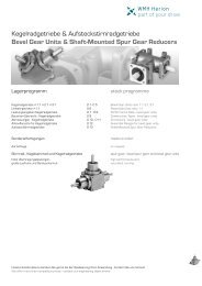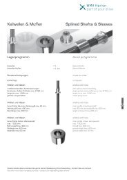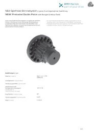
Lieferprogramm | product range - WMH Herion
Lieferprogramm | product range - WMH Herion
Lieferprogramm | product range - WMH Herion

Sie wollen auch ein ePaper? Erhöhen Sie die Reichweite Ihrer Titel.
YUMPU macht aus Druck-PDFs automatisch weboptimierte ePaper, die Google liebt.
Profilschienenführung - Allgemeine Informationen<br />
Linear Guideway - General Information<br />
Tragzahlen von Profilschienenführung<br />
1. Statische Tragzahl (C 0)<br />
Wenn eine Profilschienenführung während der Bewegung oder im<br />
Stillstand übermäßig hohen Lasten oder Schlägen ausgesetzt wird,<br />
entsteht eine lokale bleibende Verformung zwischen Laufbahn und<br />
Kugeln. Sobald diese bleibende Verformung ein bestimmtes Maß<br />
überschreitet, beeinträchtigt sie den leichtgängigen Betrieb der<br />
Führung. Die statische Tragzahl entspricht laut ihrer grundsätzlichen<br />
Definition einer statischen Last, die eine bleibende Verformung von<br />
0,0001x Kugeldurchmesser an dem Kontaktpunkt hervorruft, der<br />
am stärksten belastet wird. Die Werte werden in den Tabellen für<br />
jede Profilschienenführung angegeben. Anhand dieser Tabellen kann<br />
der Konstrukteur eine passende Profilschienenführung auswählen.<br />
Die maximale statische Last, der eine Profilschienenführung<br />
ausgesetzt wird, darf die statische Tragzahl nicht überschreiten.<br />
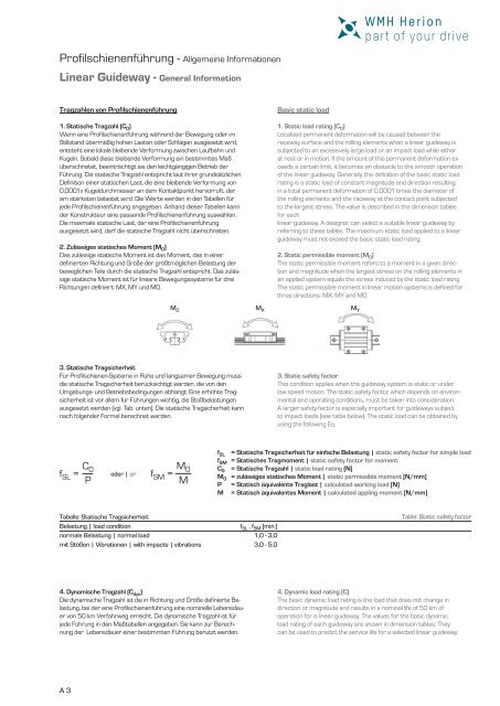
2. Zulässiges statisches Moment (M 0 )<br />
Das zulässige statische Moment ist das Moment, das in einer<br />
definierten Richtung und Größe der größtmöglichen Belastung der<br />
beweglichen Teile durch die statische Tragzahl entspricht. Das zulässige<br />
statische Moment ist für lineare Bewegungssysteme für drei<br />
Richtungen definiert: MX, MY und M0.<br />
3. Statische Tragsicherheit<br />
Für Profilschienen-Systeme in Ruhe und langsamer Bewegung muss<br />
die statische Tragsicherheit berücksichtigt werden, die von den<br />
Umgebungs- und Betriebsbedingungen abhängt. Eine erhöhte Tragsicherheit<br />
ist vor allem für Führungen wichtig, die Stoßbelastungen<br />
ausgesetzt werden (vgl. Tab. unten). Die statische Tragsicherheit kann<br />
nach folgender Formel berechnet werden.<br />
oder | or<br />
M 0<br />
Tabelle: Statische Tragsicherheit<br />
Belastung | load condition<br />
normale Belastung | normal load<br />
mit Stößen | Vibrationen | with impacts | vibrations<br />
4. Dynamische Tragzahl (C dyn)<br />
Die dynamische Tragzahl ist die in Richtung und Größe definierte Belastung,<br />
bei der eine Profilschienenführung eine nominelle Lebensdauer<br />
von 50 km Verfahrweg erreicht. Die dynamische Tragzahl ist für<br />
jede Führung in den Maßtabellen angegeben. Sie kann zur Berechnung<br />
der Lebensdauer einer bestimmten Führung benutzt werden.<br />
A 3<br />
M X<br />
Basic static load<br />
1. Static load rating (C 0)<br />
Localized permanent deformation will be caused between the<br />
raceway surface and the rolling elements when a linear guideway is<br />
subjected to an excessively large load or an impact load while either<br />
at rest or in motion. If the amount of this permanent deformation exceeds<br />
a certain limit, it becomes an obstacle to the smooth operation<br />
of the linear guideway. Generally, the definition of the basic static load<br />
rating is a static load of constant magnitude and direction resulting<br />
in a total permanent deformation of 0,0001 times the diameter of<br />
the rolling elements and the raceway at the contact point subjected<br />
to the largest stress. The value is described in the dimension tables<br />
for each<br />
linear guideway. A designer can select a suitable linear guideway by<br />
referring to these tables. The maximum static load applied to a linear<br />
guideway must not exceed the basic static load rating.<br />
2. Static permissible moment (M 0)<br />
The static permissible moment refers to a moment in a given direction<br />
and magnitude when the largest stress on the rolling elements in<br />
an applied system equals the stress induced by the static load rating.<br />
The static permissible moment in linear motion systems is defined for<br />
three directions: MX, MY and MO.<br />
M Y<br />
3. Static safety factor<br />
This condition applies when the guideway system is static or under<br />
low speed motion. The static safety factor, which depends on environmental<br />
and operating conditions, must be taken into consideration.<br />
A larger safety factor is especially important for guideways subject<br />
to impact loads (see table below). The static load can be obtained by<br />
using the following Eq.<br />
f SL = Statische Tragsicherheit für einfache Belastung | static safety factor for simple load<br />
f SM = Statisches Tragmoment | static safety factor for moment<br />
C 0 = Statische Tragzahl | static load rating [N]<br />
M 0 = zulässiges statisches Moment | static permissible moment [N/mm]<br />
P = Statisch äquivalente Traglast | calculated working load [N]<br />
M = Statisch äquivalentes Moment | calculated appling moment [N/mm]<br />
f SL , f SM [min.]<br />
1,0 - 3,0<br />
3,0 - 5,0<br />
Table: Static safety factor<br />
4. Dynamic load rating (C)<br />
The basic dynamic load rating is the load that does not change in<br />
direction or magnitude and results in a nominal life of 50 km of<br />
operation for a linear guideway. The values for the basic dynamic<br />
load rating of each guideway are shown in dimension tables. They<br />
can be used to predict the service life for a selected linear guideway.