Installation Guide - LANCOM Systems
Installation Guide - LANCOM Systems
Installation Guide - LANCOM Systems

Erfolgreiche ePaper selbst erstellen
Machen Sie aus Ihren PDF Publikationen ein blätterbares Flipbook mit unserer einzigartigen Google optimierten e-Paper Software.
<strong>LANCOM</strong> GS-2352<br />
<strong>LANCOM</strong> GS-2326<br />
<strong>LANCOM</strong> GS-2326P
© 2013 <strong>LANCOM</strong> <strong>Systems</strong> GmbH, Würselen (Germany). Alle<br />
Rechte vorbehalten.<br />
Alle Angaben in dieser Dokumentation sind nach sorgfältiger<br />
Prüfung zusammengestellt worden, gelten jedoch nicht<br />
als Zusicherung von Produkteigenschaften. <strong>LANCOM</strong> <strong>Systems</strong><br />
haftet ausschließlich in dem Umfang, der in den Verkaufs-<br />
und Lieferbedingungen festgelegt ist.<br />
Weitergabe und Vervielfältigung der zu diesem Produkt<br />
gehörenden Dokumentation und Software und die Verwendung<br />
ihres Inhalts sind nur mit schriftlicher Erlaubnis von<br />
<strong>LANCOM</strong> <strong>Systems</strong> gestattet. Änderungen, die dem technischen<br />
Fortschritt dienen, bleiben vorbehalten.<br />
Windows®, Windows Vista, Windows NT® und Microsoft®<br />
sind eingetragene Marken von Microsoft, Corp.<br />
Das <strong>LANCOM</strong> <strong>Systems</strong>-Logo, LCOS und die Bezeichnung<br />
<strong>LANCOM</strong> sind eingetragene Marken der <strong>LANCOM</strong> <strong>Systems</strong><br />
GmbH. Alle übrigen verwendeten Namen und Bezeichnungen<br />
können Marken oder eingetragene Marken ihrer jeweiligen<br />
Eigentümer sein.<br />
<strong>LANCOM</strong> <strong>Systems</strong> behält sich vor, die genannten Daten<br />
ohne Ankündigung zu ändern und übernimmt keine Gewähr<br />
für technische Ungenauigkeiten und/oder Auslassungen.<br />
Produkte von <strong>LANCOM</strong> <strong>Systems</strong> enthalten Software, die vom<br />
„OpenSSL Project“ für die Verwendung im „OpenSSL Toolkit“<br />
entwickelt wurde (http://www.openssl.org/).<br />
Produkte von <strong>LANCOM</strong> <strong>Systems</strong> enthalten kryptographische<br />
Software, die von Eric Young (eay@cryptsoft.com) geschrieben<br />
wurde.<br />
Produkte von <strong>LANCOM</strong> <strong>Systems</strong> enthalten Software, die von<br />
der NetBSD Foundation, Inc. und ihren Mitarbeitern entwickelt<br />
wurde.<br />
Produkte von <strong>LANCOM</strong> <strong>Systems</strong> enthalten das LZMA SDK,<br />
das von Igor Pavlov entwickelt wurde.<br />
<strong>LANCOM</strong> <strong>Systems</strong> GmbH<br />
Adenauerstr. 20/B2<br />
52146 Würselen<br />
Deutschland<br />
© 2013 <strong>LANCOM</strong> <strong>Systems</strong> GmbH, Würselen (Germany). All<br />
rights reserved.<br />
While the information in this manual has been compiled<br />
with great care, it may not be deemed an assurance of product<br />
characteristics. <strong>LANCOM</strong> <strong>Systems</strong> shall be liable only to<br />
the degree specified in the terms of sale and delivery.<br />
The reproduction and distribution of the documentation and<br />
software supplied with this product and the use of its contents<br />
is subject to written authorization from <strong>LANCOM</strong> <strong>Systems</strong>.<br />
We reserve the right to make any alterations that arise<br />
as the result of technical development.<br />
Windows®, Windows Vista, Windows NT® and Microsoft®<br />
are registered trademarks of Microsoft, Corp.<br />
The <strong>LANCOM</strong> <strong>Systems</strong> logo, LCOS and the name <strong>LANCOM</strong><br />
are registered trademarks of <strong>LANCOM</strong> <strong>Systems</strong> GmbH. All<br />
other names or descriptions used may be trademarks or<br />
registered trademarks of their owners.<br />
Subject to change without notice. No liability for technical<br />
errors or omissions.<br />
Products from <strong>LANCOM</strong> <strong>Systems</strong> include software developed<br />
by the OpenSSL Project for use in the OpenSSL Toolkit<br />
(http://www.openssl.org/).<br />
Products from <strong>LANCOM</strong> <strong>Systems</strong> include cryptographic software<br />
written by Eric Young (eay@cryptsoft.com).<br />
Products from <strong>LANCOM</strong> <strong>Systems</strong> include software developed<br />
by the NetBSD Foundation, Inc. and its contributors.<br />
Products from <strong>LANCOM</strong> <strong>Systems</strong> contain the LZMA SDK<br />
developed by Igor Pavlov.<br />
<strong>LANCOM</strong> <strong>Systems</strong> GmbH<br />
Adenauerstr. 20/B2<br />
52146 Würselen<br />
Deutschland<br />
www.lancom.de<br />
Würselen, Mai 2013<br />
www.lancom.de<br />
Würselen, Mai 2013<br />
111107/0513
<strong>Installation</strong> <strong>Guide</strong> <strong>LANCOM</strong> GS-2326/GS-2326P/GS-2352<br />
Kapitel 1: Einleitung<br />
1 Einleitung<br />
1.1 Überblick<br />
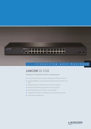
Die Modelle der Serie GS-2326/2352 präsentieren sich als preiswerte Managed<br />
Switches, mit denen Sie eine zuverlässinge Infrastruktur für Ihr Netzwerk<br />
aufbauen. Die Switche umfassen zahlreiche intelligente Funktionen, mit den<br />
Sie die Verfügbarkeit von geschäftskritischen Anwendungen verbessern, sensitive<br />
Daten schützen und die Bandbreite im Netzwerk optimieren können.<br />
Zusammen mit der einfachen <strong>Installation</strong> und Nutzung sind die Switche die<br />
ideale Kombination aus Wirtschaftlichkeit und technischen Funktionen für<br />
den Aufbau von Netzwerken vom Small-Business-Bereich bis hin zu Enterprise-Anwendungen.<br />
Alle Modelle der Serie bieten die erweiterten Sicherheits-<br />
und Verwaltungsmöglichkeiten sowie Netzwerkfunktionen zur<br />
Unterstützung der wichtigsten Anwendungen inlusive Daten, Sprache, Sicherheit<br />
und drahtloser Netzwerke.<br />
DE<br />
1.2 Switch-Architektur<br />
Der Switch basiert auf einer optimierten Switching-Struktur, welche den<br />
gleichzeitigen Transport von vielfachen Datenpaketen auf alle Ports mit voller<br />
Geschwindigkeit (wire-speed) bei geringen Latenzzeiten ermöglicht. Außerdem<br />
unterstützt der Switch Full-Duplex auf allen Ports und verdoppelt so die<br />
effektive Bandbreite der Verbindungen.<br />
Der Switch nutzt die Store-and-Forward-Methode und stellt so eine maximale<br />
Daten-Integrität sicher. Bei dieser Methode wird jedes Datenpaket in einem<br />
Buffer gespeichert und validiert, bevor der Switch es weiterleitet. Auf diese<br />
Weise verhindert der Switch das Verbreiten von fehlerhaften Paketen im Netzwerk.<br />
1.3 Netzwerk-Management<br />
Der Switch unterstützt die Konfiguration über eine web-basierte Oberfläche<br />
oder Telnet. Zusätzlich enthält der Switch einen eingebauten Netzwerk-<br />
Management-Agenten, welcher die Verwaltung über SNMP oder RMON<br />
(Gruppe 1, 2, 3, 9) erlaubt.<br />
Für das Outband-Management bieten der GS-2326 und GS-2326P einen<br />
RJ45-Konsolen-Port an der Frontseite an, der GS-2352 einen seriellen Port an<br />
3
<strong>Installation</strong> <strong>Guide</strong> <strong>LANCOM</strong> GS-2326/GS-2326P/GS-2352<br />
Kapitel 2: Hardware- Beschreibung<br />
der Rückseite. An diesen Port können Sie mit Hilfe eines Null-Modem-Kabels<br />
einen PC zur Konfiguration und Überwachung anschließen.<br />
I<br />
Weitere Informationen zu den Management-Funktionen finden Sie im<br />
Benutzerhandbuch.<br />
DE<br />
2 Hardware-Beschreibung<br />
2.1 1000BASE-T Ports<br />
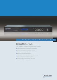
<strong>LANCOM</strong> GS-2352<br />
Vorderseite<br />
Je nach Modell bietet der Switch eine unterschiedliche Anzahl von 1000BASE-<br />
T RJ-45 Ports<br />
<br />
<br />
Ein <strong>LANCOM</strong> GS-2326(P) verfügt über 24 1000BASE-T-Ports<br />
Ein <strong>LANCOM</strong> GS-2352 verfügt über 48 1000BASE-T-Ports<br />
Alle RJ-45 Ports unterstützen den automatischen MDI/MDI-X-Betrieb, automatische<br />
Aushandlung der Übertragungsgeschwindigkeit und der Fluss-Kontrolle<br />
nach IEEE 802.3x.<br />
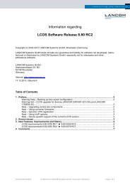
System LED<br />
System<br />
GS-2352<br />
LED Mode-Anzeige<br />
TP Ports<br />
SFP Slots<br />
10 G SFP+<br />
Link/Act<br />
Speed<br />
Mode<br />
LED Mode-Schalter<br />
TP Port LEDs<br />
SFP LEDs<br />
<strong>LANCOM</strong> GS-2352<br />
Rückseite<br />
Serieller Anschluss<br />
Anschluss Stromversorgung<br />
4
<strong>Installation</strong> <strong>Guide</strong> <strong>LANCOM</strong> GS-2326/GS-2326P/GS-2352<br />
Kapitel 2: Hardware- Beschreibung<br />
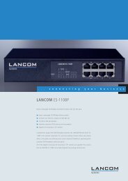
<strong>LANCOM</strong> GS-2326(P)<br />
Vorderseite<br />
Power LED<br />
Serieller Anschluss<br />
TP Ports<br />
SFP Slots<br />
DE<br />
<strong>LANCOM</strong> GS-2326(P)<br />
Rückseite<br />
Reset-Taster<br />
TP Port LEDs<br />
SFP LEDs<br />
Anschluss Stromversorgung<br />
2.2 SFP Transceiver-Slots<br />
Je nach Modell bietet der Switch eine unterschiedliche Anzahl von Small Form<br />
Factor Pluggable (SFP) Transceiver-Slots:<br />
Ein <strong>LANCOM</strong> GS-2326(P) verfügt über 2 SFP-Ports<br />
Ein <strong>LANCOM</strong> GS-2352 verfügt über 4 SFP+-Ports<br />
I<br />
Bitte informieren Sie sich im Datenblatt Ihres Modells über die unterstützten<br />
SFP-Transceiver.<br />
2.3 LED's<br />
Der Switch verfügt über Anzeigeelemente an der Vorderseite zur Darstellung<br />
der System- und Port-Zustände, welche die <strong>Installation</strong> und die Fehlersuche<br />
vereinfachen. Verwenden Sie den Mode-Taster (nur <strong>LANCOM</strong> GS-2352), um<br />
die Anzeige zwischen Speed oder Link/Act umzuschalten. Der <strong>LANCOM</strong> GS-<br />
2326 verfügt über separate LEDs an den jeweiligen Ports für Speed (links)<br />
5
<strong>Installation</strong> <strong>Guide</strong> <strong>LANCOM</strong> GS-2326/GS-2326P/GS-2352<br />
Kapitel 3: Netzwerkplanung<br />
oder Link/Act (rechts). Die folgende Tabelle zeigt die Details zu den einzelnen<br />
Anzeigeelementen:<br />
LED Zustand Beschreibung<br />
TP Link/Act Grün dauerhaft TP Link vorhanden<br />
DE<br />
Grün blinkend<br />
Datenverkehr<br />
TP Speed Grün dauerhaft TP Link mit 1000 MBit/s<br />
Orange dauerhaft<br />
TP Link mit 100 MBit/s<br />
SFP Link/Act Grün dauerhaft SFP vorhanden<br />
Grün blinkend<br />
Datenverkehr<br />
SFP Speed Grün dauerhaft Link mit 1000 MBit/s<br />
System/Power Grün dauerhaft Stromversorgung vorhanden<br />
Aus<br />
Gerät ausgeschaltet<br />
2.4 Stromversorgung<br />
Auf der Rückseite des Gerätes finden Sie die Buchse für die Stromversorgung<br />
über ein Kaltgerätekabel.<br />
3 Netzwerkplanung<br />
3.1 Einführung in das Switching<br />
Ein Switch ermöglicht das zeitgleiche Übertragen von zahlreichen Datenpaketen,<br />
er kann daher Netzwerke effektiver als andere Geräte in einzelne Bereiche<br />
aufteilen. Switche haben sich so zu einer der wichtigsten Komponenten in der<br />
modernen Netzwerk-Technologie entwickelt.<br />
Wenn Performance-Engpässe im Netzwerk durch die Anhäufung von Datenpaketen<br />
am Netzwerkanschluss hervorgerufen werden (z.B. bei File-Servern),<br />
kann das Netzwerkgerät an einen Switch-Port angeschlossen werden. Durch<br />
die Nutzung des Full-Duplex-Modus verdoppelt der Switch den Datendurchsatz<br />
in diesem Segment.<br />
Wenn Netzwerke auf einer Repeater-Struktur basieren (mittels Hubs) ist die<br />
Entfernung zwischen den Endpunkten durch die maximale Anzahl der Zwischenschritte<br />
(Hops) beschränkt. Ein Switch kann hingegen ein Netzwerk in<br />
mehrere und besser mkontrollierbare Segmente aufteilen, diese wieder zu<br />
6
<strong>Installation</strong> <strong>Guide</strong> <strong>LANCOM</strong> GS-2326/GS-2326P/GS-2352<br />
Kapitel 4: <strong>Installation</strong><br />
größeren Netzwerken verbinden und so die Beschränkingen durch den maximalen<br />
Hop-Count überwinden.<br />
Ein Switch kann einfach in jedes Netzwetk (Ethernet, Fast Ethernet, oder Gigabit<br />
Ethernet) integriert werden und so bei Weiterverwendung der vorhandenen<br />
Kabel und Netzwerkkarten die Bandbreite deutlich steigern.<br />
3.2 Anwendungsbeispiele<br />
DE<br />
Die Modelle der Serie GS-23xx verfügen über 24 bzw. 48 Gigabit Ethernet TP-<br />
Ports mit Auto-MDIX sowie 2 bzw. 4 Slots für wechselbare SFP-Transceiver,<br />
welche Glasfaserverbindungen mit LC- oder BiDi-LC-Modulen unterstützen.<br />
Über das Segmentieren des Netzwerkes hinaus bieten die Modelle zahlreiche<br />
Optionen für verschiedene Netzwerk-Topologien. Einige typische Anwendungen<br />
sind in den folgenden Abschnitten beschrieben.<br />
Die Switche ermöglichen u.a. die folgenden Anwendungen:<br />
<br />
<br />
<br />
Kopplung von mehreren entfernten Standorten in Enterprise- oder Small-<br />
Business-Strukturen<br />
Peer-to-Peer-Anwendungen zur Kopplung zweier entfernter Büros<br />
Office-Netzwerke<br />
4 <strong>Installation</strong><br />
4.1 Aufstellungsort<br />
Der Switch kann in einem üblichen 19"-Rack montiert oder auf einer ebenen<br />
Fläche aufgestellt werden. Stellen sie die folgenden Voraussetzungen für den<br />
Aufstellungsort sicher:<br />
In der Nähe der anzuschließenden Geräte und in der Nähe einer Stromversorgung.<br />
Umgebungstemperatur zwischen 0 und 40°C und Luftfeuchtigkeit zwischen<br />
10% und 90%, nicht-kondensierend.<br />
Leicht zugänglich für <strong>Installation</strong>, Verkabelung und Wartung.<br />
Gut sichtbar zur Überprüfung der LED's.<br />
I<br />
Stellen Sie sicher, dass die Twisted-Pair-Kabel nicht direkt neben<br />
Stromversorgungen, Radios oder anderen Sendern verlaufen.<br />
7
<strong>Installation</strong> <strong>Guide</strong> <strong>LANCOM</strong> GS-2326/GS-2326P/GS-2352<br />
Kapitel 4: <strong>Installation</strong><br />
I<br />
Stellen<br />
Sie sicher, dass der Switch an einer separaten, geerdeten<br />
Stromversorgung mit 100 bis 240 VAC, 50 bis 60 Hz angeschlossen ist.<br />
4.2 Ethernet-Verkablung<br />
DE<br />
Um den einwandfreien Betrieb bei der <strong>Installation</strong> des Switches im Netzwerk<br />
sicherzustellen, verwenden Sie ausschließlich Kabel, welche für 100BASE-TX<br />
oder 1000BASE-T geeignet sind. Prüfen Sie die folgenden Aspekte für die<br />
aktuelle <strong>Installation</strong> Ihres Netzwerks:<br />
<br />
<br />
<br />
<br />
<br />
Kabel: Unshielded Twisted Pair (UTP) oder Shielded Twisted Pair (STP) mit<br />
RJ45-Steckern; Kategorie 5 oder Kategorie 5e mit einer maximalen Länge<br />
von 100 Metern empfohlen für 100BASE-TX, und Kategorie 5e oder 6 mit<br />
einer maximalen Länge von 100 Metern empfohlen für 1000BASE-T<br />
Schutz vor störenden Radio-Frequenzen<br />
Spannungsschutz<br />
Trennung von Kabeln zur Stromversorgung und Datenverkabelung<br />
Sichere Verbindungen mit unbeschädigten Kabeln, Steckern und Abschirmungen<br />
4.3 Lieferumfang und benötigtes Zubehör<br />
Bitte prüfen Sie den Inhalt der Verpackung auf Vollständigkeit, bevor Sie mit<br />
der <strong>Installation</strong> beginnen. Neben dem <strong>LANCOM</strong> Switch sollte der Karton folgendes<br />
Zubehör für Sie bereithalten:<br />
<br />
<br />
<br />
<br />
Netzkabel zum Anschluss an die Stromversorgung<br />
19’’-Montagewinkel (2 Stück) und Befestigungsmaterial<br />
<strong>LANCOM</strong>-CD<br />
Gedruckte Dokumentation<br />
Falls etwas fehlen sollte, wenden Sie sich bitte umgehend an Ihren Händler<br />
oder an die Kontaktadresse, die auf dem Lieferschein zu Ihrem Gerät angegeben<br />
ist.<br />
Stellen Sie sicher, dass Sie außerdem alle evtl. notwendigen Zubehörteile zur<br />
Verfügung haben, bevor Sie mit der <strong>Installation</strong> beginnen.<br />
8
<strong>Installation</strong> <strong>Guide</strong> <strong>LANCOM</strong> GS-2326/GS-2326P/GS-2352<br />
Kapitel 4: <strong>Installation</strong><br />
4.4 Montage und Anschluss des <strong>LANCOM</strong> Switches<br />
Die <strong>Installation</strong> des <strong>LANCOM</strong> Switches erfolgt in folgenden Schritten:<br />
Montage – montieren Sie das Gerät in einem freien 19”-Einschub in<br />
einem entsprechenden Serverschrank. Nutzen Sie dazu die mitgeleiferten<br />
19”-Montagewinkel. Bringen Sie ggf. die Gummifüße auf der Unterseite<br />
des Gerätes an, um Kratzer auf den Oberflächen anderer Geräte zu vermeiden.<br />
DE<br />
I<br />
Achten<br />
Sie auf eine ausreichende Belüftung des Gerätes, um Schäden<br />
durch übermäßige Wärmeentwicklung zu vermeiden.<br />
LAN-Anschluss – schließen Sie die Netzwerkgeräte über ein geeignetes<br />
Twisted-Pair-Kabel (TP-Kabel) an die Ports des <strong>LANCOM</strong> Switches an. Die<br />
Anschlüsse erkennen die mögliche Überrtagungsgeschwindigkeit und die<br />
Pin-Belegung automatisch (Autosensing).<br />
I<br />
Verwenden Sie nur normgerechte TP-Kabel der Kategorie CAT 5e oder<br />
besser mit einer maximalen Länge von 100 m, um eine einwandfreie<br />
Datenübertragung zu gewährleisten. Crossover-Kabel mit gekreuzten<br />
Kontakten können aufgrund der Autosensing-Funktion ebenfalls verwendet<br />
werden.<br />
I<br />
Zur<br />
Nutzung der Glasfaseranschlüsse sind zusätzliche Module erforderlich,<br />
die Sie als Zubehör erwerben können.<br />
Mit Spannung versorgen und einschalten – versorgen Sie das Gerät über<br />
das Kaltgerätekabel mit Spannung.<br />
9
<strong>Installation</strong> <strong>Guide</strong> <strong>LANCOM</strong> GS-2326/GS-2326P/GS-2352<br />
Kapitel 5: <strong>LANCOM</strong> Switch konfigurieren und überwachen<br />
Betriebsbereit? – Nach einem kurzen Selbsttest des Geräts leuchtet die<br />
Power-LED (<strong>LANCOM</strong> GS-2326/<strong>LANCOM</strong> GS-2326P) bzw. System-LED<br />
(<strong>LANCOM</strong> GS-2352) permanent. Grün leuchtende Link/Act-LEDs zeigen<br />
an, an welchen LAN-Anschlüssen funktionierende Verbindungen hergestellt<br />
sind.<br />
DE<br />
5 <strong>LANCOM</strong> Switch konfigurieren und<br />
überwachen<br />
5.1 Konfigurationsmöglichkeiten<br />
Zur Konfiguration des Geräts stehen zwei unterschiedliche Wege zur Auswahl:<br />
<br />
<br />
Grafische Benutzeroberfläche über einen Browser (WEBconfig): diese<br />
Konfigurationsmöglichkeit können Sie nur über eine Netzwerkverbindung<br />
nutzen, wenn Sie das Gerät von Ihrem Rechner aus über die IP-Adresse<br />
erreichen können. Die Rechner benötigen dazu ein Betriebssystem mit<br />
TCP/IP-Unterstützung, z.B. Windows 8, Windows 7, Windows Vista,<br />
Windows XP, Linux, BSD Unix, Apple Mac OS sowie einen Zugang zum<br />
LAN über das TCP/IP-Protokoll und einen Browser.<br />
Textorientierte Konfiguration über eine Konsole (Command Line Interface<br />
– CLI): diese Konfigurationsmöglichkeit können Sie über Telnet, Hyperterminal<br />
o.ä. sowohl über eine Netzwerkverbindung als auch über eine<br />
Direktverbindung über die serielle Konfigurationsschnittstelle (RS-232)<br />
nutzen.<br />
Unter Windows können Sie die LANtools nutzen, um die <strong>LANCOM</strong> Switches zu<br />
suchen und überwachen:<br />
<br />
<br />
LANconfig ist das Windows-Konfigurationsprogramm für alle <strong>LANCOM</strong>-<br />
Geräte. Mit LANconfig können Sie alle <strong>LANCOM</strong>-Geräte im Netzwerk<br />
suchen. Für einen <strong>LANCOM</strong> Switch können Sie damit die webbasierte<br />
Konfiguration starten.<br />
Mit LANmonitor überwachen Sie auf einem Windows-Rechner alle<br />
<strong>LANCOM</strong>-Geräte. Für einen <strong>LANCOM</strong> Switch können Sie damit alle wichtigen<br />
Statusinformationen wie z.B. den Link-Status der Ports einsehen.<br />
Legen Sie zur <strong>Installation</strong> von LANconfig oder LANmonitor die Produkt-CD in<br />
Ihr Laufwerk ein. Daraufhin startet das Setup-Programm automatisch.<br />
I<br />
Sollte das Setup nicht automatisch starten, so rufen Sie die Datei<br />
AUTORUN.EXE aus dem Hauptverzeichnis der beiliegenden CD auf.<br />
10
<strong>Installation</strong> <strong>Guide</strong> <strong>LANCOM</strong> GS-2326/GS-2326P/GS-2352<br />
Kapitel 5: <strong>LANCOM</strong> Switch konfigurieren und überwachen<br />
5.1.1 WEBconfig starten<br />
Sie können die Konfiguration über einen Browser auf zwei Wegen starten:<br />
<br />
<br />
Wenn Ihnen die IP-Adresse des Gerätes bekannt ist, geben Sie einfach die<br />
IP-Adresse in die Adresszeile des Browsers ein. Die bei Auslieferung gültigen<br />
Zugangsdaten lauten: Username „admin“, Kennwort „admin“.<br />
Wenn Ihnen die IP-Adresse des Gerätes nicht bekannt ist, können Sie mit<br />
Hilfe von LANconfig danach suchen. Starten Sie dazu LANconfig über<br />
Start / Programme / <strong>LANCOM</strong> / LANconfig. LANconfig sucht automatisch<br />
nach erreichbaren Geräten in Ihrem Netzwerk. Neben anderen evtl. vorhandenen<br />
<strong>LANCOM</strong>-Routern oder Access Points wird dabei auch ein<br />
<strong>LANCOM</strong> Switch gefunden und in der Liste angezeigt. Mit einem Doppelklick<br />
auf diesen Eintrag starten Sie automatisch einen Browser zur entsprechenden<br />
IP-Adresse.<br />
DE<br />
Welche IP-Adresse hat mein <strong>LANCOM</strong> Switch?<br />
Die aktuelle IP-Adresse des <strong>LANCOM</strong> Switches nach dem Einschalten hängt<br />
von der Konstellation des Netzwerks ab.<br />
<br />
Netzwerk mit DHCP-Server – Der <strong>LANCOM</strong> Switch ist bei Auslieferung auf<br />
den Auto-DHCPModus eingestellt, er sucht also nach einem DHCP-Server,<br />
der ihm eine IP-Adresse, die Subnetzmaske und die Adresse des Gateways<br />
zuweisen kann. Die zugewiesene IP-Adresse kann dann über entsprechende<br />
Tools (z.B. LANconfig) oder den DHCP-Server ermittelt werden.<br />
Handelt es sich beim DHCP-Server z.B. um ein <strong>LANCOM</strong>-Gerät, so kann<br />
die IP-Adresse des <strong>LANCOM</strong> Switches in der DHCP-Tabelle nachgesehen<br />
11
<strong>Installation</strong> <strong>Guide</strong> <strong>LANCOM</strong> GS-2326/GS-2326P/GS-2352<br />
Kapitel 5: <strong>LANCOM</strong> Switch konfigurieren und überwachen<br />
DE<br />
<br />
werden. Der <strong>LANCOM</strong> Switch kann in diesem Fall von jedem Rechner aus<br />
dem Netzwerk erreicht werden, der ebenfalls seine IP-Adresse vom DHCP-<br />
Server bezieht.<br />
Netzwerk ohne DHCP-Server – Falls im Netzwerk kein DHCP-Server vorhanden<br />
ist, so verwendet der <strong>LANCOM</strong> Switch je nach Modell die Adresse<br />
“172.23.56.250” oder “172.23.56.251”. Der <strong>LANCOM</strong> Switch kann in<br />
diesem Fall von jedem Rechner aus dem Netzwerk erreicht werden, der<br />
auf eine IP-Adresse aus dem Adressbereich “172.23.56.x” eingestellt ist.<br />
5.1.2 Command Line Interface über Netzwerk starten<br />
Wenn Ihnen die IP-Adresse des Gerätes bekannt ist (siehe auch vorhergehender<br />
Abschnitt) und der <strong>LANCOM</strong> Switch von Ihrem Rechner aus über das Netzwerk<br />
erreichbar ist, können Sie das Command Line Interface über das<br />
Netzwerk nutzen.<br />
Starten Sie dazu z.B. eine Konsole wie Telnet und geben Sie als Ziel die<br />
aktuelle IP-Adresse des Gerätes ein.<br />
Melden Sie sich mit Benutzername und Kennwort an (Default: admin,<br />
Kennwort: admin).<br />
5.1.3 Command Line Interface über serielle Verbindung starten<br />
Wenn Ihnen die IP-Adresse des Gerätes nicht bekannt ist, können Sie das<br />
Command Line Interface über eine serielle Direktverbindung nutzen.<br />
Stellen Sie über das serielle Konfigurationskabel eine Verbindung zwischen<br />
dem <strong>LANCOM</strong> Switch und dem Konfigurationsrechner her (siehe<br />
’Montage und Anschluss des <strong>LANCOM</strong> Switch’).<br />
Starten Sie auf dem Konfigurationsrechner ein Terminalprogramm, z. B.<br />
PuTTY. Verwenden Sie dabei als Verbindungsparameter:<br />
Baudrate: 115200<br />
Stop Bits: 1<br />
Data Bits: 8<br />
Parity: N<br />
Fluss-Kontrolle: keine<br />
Melden Sie sich mit Benutzername und Kennwort an (Default: admin,<br />
Kennwort: admin).<br />
12
<strong>Installation</strong> <strong>Guide</strong> <strong>LANCOM</strong> GS-2326/GS-2326P/GS-2352<br />
Kapitel 5: <strong>LANCOM</strong> Switch konfigurieren und überwachen<br />
5.2 <strong>LANCOM</strong> Switch mit LANmonitor überwachen<br />
Der Zustand des Gerätes und der einzelnen Ports kann über die LEDs an der<br />
Vorderseite beobachtet werden. Mit dem LANmonitor kann diese Überwachung<br />
sehr komfortabel von jedem Arbeitsplatz aus geschehen – ohne direkte<br />
Sichtverbindung zu den LEDs. Neben den Statusinformationen der LEDs können<br />
mit dem LANmonitor noch weitere wichtige Zustandsinformationen über<br />
die Ports abgefragt werden.<br />
DE<br />
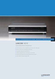
5.2.1 Status der Ethernet-Ports<br />
Der LANmonitor zeigt für alle Ethernet-Ports des Gerätes den aktuellen Status<br />
an. Dabei wird sowohl der vom Administrator konfigurierte Status angezeigt<br />
(Config-Status) als auch der tatsächliche Verbindungs-Status des Ports (Link-<br />
Status). Dazu wird jeder Port mit zwei farbigen Punkten im LANmonitor dargestellt:<br />
Der linke Punkt zeigt den Config-Status:<br />
<br />
<br />
grau: der Port ist in der Konfiguration deaktiviert<br />
gelb: der Port ist in der Konfiguration aktiviert<br />
Der rechte Punkt zeigt den Link-Status:<br />
<br />
<br />
grau: an den Port ist kein aktives Netzwerkgerät angeschlossen<br />
grün: an den Port ist ein Netzwerkgerät angeschlossen und aktiv<br />
Neben dem Status zeigt LANmonitor außerdem die VLAN-ID für jeden Port an<br />
und für aktive Ports mit aktiven Netzwerkgeräten die ermittelte Übertragungsgeschwindigkeit.<br />
13
<strong>Installation</strong> <strong>Guide</strong> <strong>LANCOM</strong> GS-2326/GS-2326P/GS-2352<br />
Chapter 1: Introduction<br />
1 Introduction<br />
1.1 Overview<br />
EN<br />
The GS-2326/2352 series, <strong>LANCOM</strong>s next generation network solution, is a<br />
portfolio of affordable managed switches that provides a reliable infrastructure<br />
for your business network. These switches deliver more intelligent features<br />
you need to improve the availability of your critical business<br />
applications, protect your sensitive information, and optimize your network<br />
bandwidth to deliver information and applications more effectively. Easy to<br />
set up and use, it provides the ideal combination of affordability and capabilities<br />
for entry level Networking includes Small Business or enterprise application<br />
and helps you create a more efficient, better-connected workforce.<br />
1.2 Switch architecture<br />
The switch performs a wire-speed, non-blocking switching fabric. This allows<br />
wire-speed transport of multiple packets at low latency on all ports simultaneously.<br />
The switch also features full-duplex capability on all ports, which<br />
effectively doubles the bandwidth of each connection.<br />
This switch uses store-and-forward technology to ensure maximum data integrity.<br />
With this technology, the entire packet must be received into a buffer<br />
and checked for validity before being forwarded. This prevents errors from<br />
being propagated throughout the network.<br />
1.3 Network management<br />
The switch can also be managed over the network with a web browser or Telnet<br />
application. The switch includes a built-in network management agent<br />
that allows it to be managed in-band using SNMP or RMON (Groups 1, 2, 3,<br />
9) protocols.<br />
For out-band management the GS-2326 and GS-2326P offer a RJ45 console<br />
port connector on the front panel, the GS-2352 a serial port on the back.<br />
I<br />
For a detailed description of the management features, refer to the<br />
User’s manual.<br />
14
<strong>Installation</strong> <strong>Guide</strong> <strong>LANCOM</strong> GS-2326/GS-2326P/GS-2352<br />
Chapter 2: Hardware<br />
2 Hardware<br />
2.1 1000BASE-T Ports<br />
<strong>LANCOM</strong> GS-2352<br />
front<br />
Depending on the model the switch offers different numbers of 1000BASE-T<br />
RJ-45 ports:<br />
<br />
<br />
A <strong>LANCOM</strong> GS-2326(P) offers 24 1000BASE-T ports<br />
A <strong>LANCOM</strong> GS-2352 offers 48 1000BASE-T ports<br />
All RJ-45 ports support automatic MDI/MDI-X operation, auto-negotiation<br />
and IEEE 802.3x auto-negotiation of flow control, so the optimum data rate<br />
and transmission can be selected automatically.<br />
System LED<br />
LED Mode LED<br />
TP Ports<br />
SFP Slots<br />
EN<br />
GS-2352<br />
10 G SFP+<br />
System<br />
Link/Act<br />
Speed<br />
Mode<br />
LED Mode Switch<br />
TP Port LEDs<br />
SFP LEDs<br />
<strong>LANCOM</strong> GS-2352<br />
rear<br />
Serial Connector<br />
Power Connector<br />
<strong>LANCOM</strong> GS-2326(P)<br />
front<br />
Power LED<br />
Serial Connector<br />
TP Ports<br />
SFP Slots<br />
Reset Button<br />
TP Port LEDs<br />
SFP LEDs<br />
15
<strong>Installation</strong> <strong>Guide</strong> <strong>LANCOM</strong> GS-2326/GS-2326P/GS-2352<br />
Chapter 2: Hardware<br />
<strong>LANCOM</strong> GS-2326(P)<br />
rear<br />
Power Connector<br />
EN<br />
2.2 SFP Transceiver Slots<br />
2.3 LEDs<br />
Depending on the model the switch offers different numbers of Small Form<br />
Factor Pluggable (SFP) Transceiver Slots:<br />
A <strong>LANCOM</strong> GS-2326(P) offers 2 SFP slots<br />
A <strong>LANCOM</strong> GS-2352 offers 4 SFP+ slots<br />
I<br />
Please find a list of supported SFP transceivers in your devices datasheet.<br />
The switch includes a display panel for system and port indications that simplify<br />
installation and network troubleshooting. Use the mode button<br />
(<strong>LANCOM</strong> GS-2352 only) to select the Speed or Link/Act LED function. The<br />
<strong>LANCOM</strong> GS-2326 provides seperate port LEDs for Speed (left) or Link/Act<br />
(right). Details are shown below and described in the following table:<br />
LED Condition Description<br />
TP Link/Act Green permanent TP Link up<br />
Green blinking<br />
Data traffic<br />
TP Speed Green permanent TP Link with 1000 MBps<br />
Orange permanent<br />
TP Link with 100 MBps<br />
SFP Link/Act Green permanent SFP Link up<br />
Green blinking<br />
Data traffic<br />
SFP Speed Green permanent Link with 1000 MBps<br />
System/Power Green permanent Power up<br />
Off<br />
Device switched off<br />
16
<strong>Installation</strong> <strong>Guide</strong> <strong>LANCOM</strong> GS-2326/GS-2326P/GS-2352<br />
Chapter 3: Network planning<br />
2.4 Power supply<br />
There are a power sockets on the rear panel of the switch.<br />
3 Network planning<br />
3.1 Introduction to switching<br />
A network switch allows simultaneous transmission of multiple packets, it can<br />
partition a network more efficiently than bridges or routers. Therefore the<br />
switch has been recognized as one of the most important device for today’s<br />
networking technology.<br />
When performance bottlenecks are caused by congestion at the network<br />
access point such as file server, the device can be connected directly to a switched<br />
port. And, by using full-duplex mode, the bandwidth of the dedicated<br />
segment can be doubled to maximize throughput.<br />
When networks are based on repeater (hub) technology, the distance between<br />
end stations is limited by a maximum hop count. However, a switch can subdividing<br />
the network into smaller and more manageable segments, and linking<br />
them to the larger network than it turns the hop count back to zero and<br />
removes the limitation.<br />
A switch can be easily configured in any Ethernet, Fast Ethernet, or Gigabit<br />
Ethernet network to significantly increase bandwidth while using conventional<br />
cabling and network cards.<br />
EN<br />
3.2 Application examples<br />
The GS-23xx Series Switch implements 24 or 48 Gigabit Ethernet TP ports with<br />
auto MDIX and 2 or 4 slots for the removable SFP module which supports<br />
comprehensive types of fiber connection, such as LC and BiDi-LC modules. It<br />
is not only designed to segment your network, but also to provide a wide<br />
range of options in setting up network connections. Some typical applications<br />
are described below.<br />
The switch is suitable for the following applications:<br />
<br />
<br />
<br />
Remote site application is used in Enterprise or SMB<br />
Peer-to-peer application is used in two remote offices<br />
Office network<br />
17
<strong>Installation</strong> <strong>Guide</strong> <strong>LANCOM</strong> GS-2326/GS-2326P/GS-2352<br />
Chapter 4: <strong>Installation</strong><br />
4 <strong>Installation</strong><br />
4.1 Selecting a site<br />
EN<br />
The Switch can be mounted in a standard 19-inch equipment rack (via Optional<br />
Rack mount Kit) or on a flat surface. Be sure to follow the guidelines<br />
below when choosing a location.<br />
<br />
<br />
Be at the center of all the devices you want to link and near a power outlet.<br />
Be able to maintain its temperature within 0 to 40°C (32 to 104 °F) and<br />
its humidity within 10% to 90%, non-condensing.<br />
Be accessible for installing, cabling and maintaining the devices.<br />
Allow the status LEDs to be clearly visible.<br />
<br />
<br />
I<br />
Make<br />
I<br />
Make<br />
sure the twisted-pair Ethernet cable is always routed away from<br />
power lines, radios, transmitters or any other electrical interference.<br />
sure that the Switch is connected to a separate grounded power<br />
outlet that provides 100 to 240 VAC, 50 to 60 Hz.<br />
4.2 Ethernet cabling<br />
To ensure proper operation when installing the switch into a network, make<br />
sure that the current cables are suitable for 100BASE-TX or 1000BASE-T operation.<br />
Check the following criteria against the current installation of your network:<br />
<br />
<br />
<br />
<br />
<br />
Cable type: Unshielded twisted pair (UTP) or shielded twisted pair (STP)<br />
cable with RJ-45 connectors; Category 5 or Category 5e with maximum<br />
length of 100 meters is recommend 100BASE-TX, and Category 5e or 6<br />
with maximum length of 100 meters is recommend for 1000BASE-T.<br />
Protection from radio frequency interference emissions.<br />
Electrical surge suppression.<br />
Separation of electrical wires and data based network wiring.<br />
Safe connections with no damaged cables, connectors or shields<br />
18
<strong>Installation</strong> <strong>Guide</strong> <strong>LANCOM</strong> GS-2326/GS-2326P/GS-2352<br />
Chapter 4: <strong>Installation</strong><br />
4.3 Package content and accessories<br />
Before beginning with the installation, please check that nothing is missing<br />
from your package. Along with the <strong>LANCOM</strong> Switch the box should contain<br />
the following accessories:<br />
<br />
<br />
<br />
<br />
Power cord<br />
19’’ adapter (2 pieces) and mounting materials<br />
<strong>LANCOM</strong> CD<br />
Printed documentation<br />
Should anything be missing, please take up immediate contact to your dealer<br />
or to the address on the delivery note supplied with your device.<br />
Ensure that you have all additional accessories at hand which might be<br />
required during installation.<br />
EN<br />
4.4 Mounting and connecting up the <strong>LANCOM</strong> switch<br />
Installing the <strong>LANCOM</strong> switch involves the following steps:<br />
Mounting – The device is designed for mounting in an available 19” unit<br />
in a server cabinet. Make use of the supplied mounting brackets for 19"<br />
cabinets. If necessary fix the rubber pads to the underside of the device to<br />
prevent any scratching to other equipment.<br />
I<br />
Ensure<br />
that the device has sufficient ventilation to prevent damage<br />
from excessive heat build-up.<br />
LAN connection – Connect the network devices to the ports of the LAN-<br />
COM switch by means of a suitable twisted-pair cable (TP cable). The con-<br />
19
<strong>Installation</strong> <strong>Guide</strong> <strong>LANCOM</strong> GS-2326/GS-2326P/GS-2352<br />
Chapter 5: Configuring and monitoring the <strong>LANCOM</strong> switch<br />
EN<br />
I<br />
Use<br />
I<br />
If<br />
nectors automatically detect the available data transfer speeds and the<br />
pin assignment (autosensing).<br />
only standard TP cables of category CAT 5 or better with a maximum<br />
length of 100 m to ensure the best possible transfer of data.<br />
Cross-over cables can be used thanks to the auto-sensing function.<br />
optical connections are to be used, additional modules can be<br />
purchased as accessories.<br />
Supply power and switch on – Supply power to the device by means of the<br />
IEC power cable.<br />
Ready for operation? – After a brief self-test, the power LED (<strong>LANCOM</strong><br />
GS-2326 / <strong>LANCOM</strong> GS-2326P) or system LED (<strong>LANCOM</strong> GS-2352) lights<br />
up continuously. Green ink/Act LEDs show which LAN connectors are<br />
being used for a connection.<br />
5 Configuring and monitoring the <strong>LANCOM</strong><br />
switch<br />
5.1 Configuration options<br />
There are two different methods of configuring the device:<br />
By means of a graphical user interface or via a browser (WEBconfig). This<br />
option is only available if you have network access to the device's IP<br />
address from your computer. The computers require an operating system<br />
that supports TCP/IP, e.g. Windows 8, Windows 7, Windows Vista,<br />
Windows XP, Linux, BSD Unix, Apple Mac OS and also access to the LAN<br />
via the TCP/IP protocol.<br />
Text-orientated configuration via a console (Command Line Interface –<br />
CLI): This method of configuration, which requires a program such as Telnet,<br />
Hyperterminal, or similar, can be conducted over a network connection<br />
or with a direct connection via serial interface (RS-232).<br />
When working with Windows, you can use the LANtools to detect and monitor<br />
the <strong>LANCOM</strong> switch.<br />
<br />
LANconfig is the Windows configuration program for all <strong>LANCOM</strong><br />
devices. LANconfig searches for all <strong>LANCOM</strong> devices in your network. You<br />
can use this to start the Web-based configuration of a <strong>LANCOM</strong> switch.<br />
20
<strong>Installation</strong> <strong>Guide</strong> <strong>LANCOM</strong> GS-2326/GS-2326P/GS-2352<br />
Chapter 5: Configuring and monitoring the <strong>LANCOM</strong> switch<br />
<br />
With LANmonitor you can use a Windows computer to monitor all of your<br />
<strong>LANCOM</strong> devices. This program displays all important status information<br />
To install the product, place the product CD into your drive. The setup program<br />
will start automatically<br />
I<br />
If the setup does not start automatically, run AUTORUN.EXE in the<br />
root directory of the supplied CD.<br />
5.1.1 Starting WEBconfig<br />
There are two ways of starting the configuration by browser:<br />
<br />
<br />
If you know the device's IP address, simply enter this into the address line<br />
in the browser. The factory settings for accessing the device are: User<br />
name "admin", password "admin".<br />
If you do not have the device's IP number, LANconfig can be used to<br />
search for it. To start LANconfig click on Start / Programs / <strong>LANCOM</strong> / LANconfig.<br />
LANconfig automatically searches for all available devices in your<br />
network. Any available <strong>LANCOM</strong> routers or access points will be displayed<br />
in the list, including the <strong>LANCOM</strong> switch. Double-click on this entry to<br />
start the browser automatically with the correct IP address..<br />
EN<br />
What is the IP address of my <strong>LANCOM</strong> switch?<br />
The current IP address of the <strong>LANCOM</strong> switch after being switched on<br />
depends on the network constellation.<br />
21
<strong>Installation</strong> <strong>Guide</strong> <strong>LANCOM</strong> GS-2326/GS-2326P/GS-2352<br />
Chapter 5: Configuring and monitoring the <strong>LANCOM</strong> switch<br />
EN<br />
<br />
<br />
Networks with DHCP server – In its factory settings, the <strong>LANCOM</strong> switch<br />
is set for auto DHCP mode, meaning that it searches for a DHCP server to<br />
assign it an IP address, subnet mask and gateway address. The assigned<br />
IP address can only be determined by using the appropriate tools (e.g.<br />
LANconfig) or via the DHCP server. If the DHCP server is a <strong>LANCOM</strong> device,<br />
the IP address of the <strong>LANCOM</strong> switch can be read out from the DHCP<br />
table. If this is the case, the <strong>LANCOM</strong> switch can be accessed from any<br />
network computer that receives its IP address from the same DHCP server.<br />
Network without a DHCP server – If no DHCP server is present in the network,<br />
the <strong>LANCOM</strong> switch adopts an address which, depending on the<br />
model, may be "172.23.56.250" or "172.23.56.251". If this is the case,<br />
the <strong>LANCOM</strong> switch can be accessed from any network computer with its<br />
IP address set to the address range "172.23.56.x".<br />
5.1.2 Starting the Command Line Interface over the network<br />
If you know the device's IP address (see section above) and the <strong>LANCOM</strong><br />
switch is accessible from your computer via the network, the you can use the<br />
command line interface via the network.<br />
To do this, start a console such as Telnet and enter the device's IP address<br />
as the target.<br />
Log on with user name and password (default: admin, password: admin).<br />
5.1.3 Starting the Command Line Interface over the serial connection<br />
If you do not know the IP address of the device, you can use the command<br />
line interface via a serial connection.<br />
Use the serial configuration cable to connect the <strong>LANCOM</strong> switch to the<br />
configuration computer (see "Mounting and connecting up the <strong>LANCOM</strong><br />
Switch').<br />
Start a terminal program on the configuration computer, such as PuTTY.<br />
Use the following parameters for the connection:<br />
Baud rate: 115200<br />
Stop bits: 1<br />
Data bits: 8<br />
Parity: N<br />
FFlow control: none<br />
22
<strong>Installation</strong> <strong>Guide</strong> <strong>LANCOM</strong> GS-2326/GS-2326P/GS-2352<br />
Chapter 5: Configuring and monitoring the <strong>LANCOM</strong> switch<br />
Log on with user name and password (default: admin, password: admin).<br />
5.2 Monitoring the <strong>LANCOM</strong> switch with LANmonitor<br />
The current state of the device and all ports can be monitored using the LEDs<br />
on the front panel. With LANmonitor the devices can be observed from any<br />
workstation without being able to see the LEDs. Besides the status information<br />
provided by the LEDs the LANmonitor provides further important information<br />
on the ports.<br />
EN<br />
5.2.1 Ethernet port status<br />
LANmonitor displays the current status of all of the device's Ethernet ports.<br />
This includes monitoring of the state as configured by the admin (config state)<br />
and the actual state (link state) of the port. Each port is displayed with two<br />
colored symbols in LANmonitor:<br />
The left icon shows the config state:<br />
<br />
<br />
Gray: The port is deactivated in the configuration<br />
Yellow: The port is activated in the configuration<br />
The right-hand icon shows the link state:<br />
<br />
<br />
Gray: No active network device is connected to the port<br />
Green: A network device is connected to the port and active<br />
Apart from the status, LANmonitor displays the VLAN ID for each port and the<br />
detected data rate at active ports connected to active network devices.<br />
23