Datenblatt TEMZ C25 - Schwarzbeck - Mess-Elektronik
Datenblatt TEMZ C25 - Schwarzbeck - Mess-Elektronik
Datenblatt TEMZ C25 - Schwarzbeck - Mess-Elektronik

Erfolgreiche ePaper selbst erstellen
Machen Sie aus Ihren PDF Publikationen ein blätterbares Flipbook mit unserer einzigartigen Google optimierten e-Paper Software.
SCHWARZBECK MESS - ELEKTRONIK<br />
An der Klinge 29 D-69250 Schönau Tel.: 06228/1001 Fax.: (49)6228/1003<br />
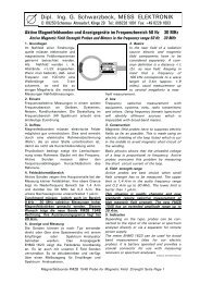
<strong>TEMZ</strong> <strong>C25</strong> 90 Ω Streifenleitung<br />
<strong>TEMZ</strong> <strong>C25</strong> 90 Ω Stripline<br />
Verwendung:<br />
Die unsymmetrische 90 Ω - Streifenleitung<br />
entspricht in Ihren Abmessungen den<br />
Anforderungen aus CISPR 25 Ed3 CDV. Mit der<br />
Streifenleitung können TEM-Wellen bis max. ca.<br />
220 MHz erzeugt werden. Im TEM-Wellenbetrieb<br />
liegen im gesamten Streifenleiter sehr homogene<br />
Feldverhältnisse vor. Oberhalb von 220 MHz<br />
existieren höhere Wellentypen, bei denen eine<br />
starke Ortsabhängigkeit der Feldstärke vorliegt.<br />
Während bei TEM-Wellenanregung die<br />
Feldstärke am Rand des Streifenleiters gering ist<br />
und zur Mitte hin ansteigt, liegt bei höheren<br />
Wellentypen der umgekehrte Fall vor; man findet<br />
die höchsten Feldstärkewerte am Rande des<br />
Septums, in der Mitte liegt in der Regel ein<br />
Feldstärke-Minimum vor. Darüberhinaus sind bei<br />
hohen Frequenzen Bereiche mit veränderter<br />
Polarisationsrichtung des Feldes vorhanden. Im<br />
Grundwellenbetrieb erfolgt bei leerer Zelle nur<br />
eine sehr geringe Abstrahlung. Etwa 8 % der<br />
eingespeisten Leistung wird in die Quelle<br />
reflektiert, bedingt durch die Impedanz von 90 Ω,<br />
dies entspricht einem mittleren nominellen<br />
VSWR von 1.8. Zur Überwachung der tatsächlich<br />
vorhandenen Feldstärke eignet sich besonders<br />
das kompakte, kostengünstige netzunabhängige<br />
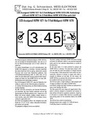
Feldstärkemessgerät VUFM 1670 und das LCD-<br />
Anzeigeteil VUFM 1671, die per Lichtwellenleiter<br />
verbunden sind. Zur Positionierung der Prüflinge<br />
sollten dielektrisch nahezu neutrale Werkstoffe<br />
verwendet werden, z.B. Schaumgummi oder<br />
Styroporplatten. Die Eignung eines Werkstoffes<br />
kann abgeschätzt werden, indem zunächst die<br />
Rückflußdämpfung bei leerer Zelle und<br />
anschließend mit dem zu untersuchenden<br />
Werkstoff gemessen wird. Gut geeignete<br />
Werkstoffe weisen eine minimale<br />
Dämpfungsänderung auf. Die Prüflinge sollten so<br />
gut wie möglich mittig im Streifenleiter plaziert<br />
werden. Zur Erhöhung der Reproduzierbarkeit<br />
sollte die exakte Positionierung der Prüflinge und<br />
insbesondere die Kabelführung dokumentiert<br />
werden.<br />
Application:<br />
The unsymmetrical 90 Ω stripline complies to<br />
the requirements of CISPR 25 Ed3 CDV. The<br />
stripline can be used to create TEM-waves up<br />
to max. 220 MHz. The fieldstrength<br />
distribution at TEM-mode operation inside the<br />
stripline is very homogenous. The stripline<br />
can also be used above 220 MHz, in this<br />
case higher modes do exist, which offer a<br />
location dependant fieldstrength<br />
characteristics. In contrast to the TEM-mode,<br />
where the fieldstrength is small at the edge of<br />
the stripline and increases towards the<br />
center, the higher modes show opposite<br />
characteristics: the fieldstrength is small at<br />
the center of the stripline and rises to<br />
maximum values at the edge of the strip<br />
conductor. Further the direction of<br />
polarisation changes at some areas during<br />
multi mode operation. At TEM-mode<br />
operation there are only small losses caused<br />
by radiation and dielectrical losses of the<br />
plastic support rods. Approx. 8% of the<br />
incident power is reflected back into the<br />
source due to the characteristic line<br />
impedance of 90 Ω, which corresponds to a<br />
nominal average VSWR of 1.8.<br />
An ideal tool for monitoring the actual<br />
fieldstrength inside the stripline is the VUFM<br />
1670 field meter with VUFM 1671 LCDdisplay<br />
unit, which are connected via a fibre<br />
optical link.<br />
For positioning of the EuT it is recommended<br />
to use (nearly) dielectric neutral material, e.g.<br />
foam or polystirene plastics. The suitability of<br />
the material can be checked as follows: the<br />
return loss of the empty cell is measured,<br />
then the material under test is placed in the<br />
cell and the insertion loss is measured again.<br />
Minimum differences in attenuation of the<br />
empty and loaded cell indicate a suitable<br />
material. The equipment under test (EuT)<br />
should be placed in the center of the stripline.<br />
It is recommended to record the EuT-position<br />
and the cable location as exactly as possible<br />
in order to achieve a good reproducability of<br />
the tests.