Datenblatt TEMZ C25 - Schwarzbeck - Mess-Elektronik
Datenblatt TEMZ C25 - Schwarzbeck - Mess-Elektronik
Datenblatt TEMZ C25 - Schwarzbeck - Mess-Elektronik

Erfolgreiche ePaper selbst erstellen
Machen Sie aus Ihren PDF Publikationen ein blätterbares Flipbook mit unserer einzigartigen Google optimierten e-Paper Software.
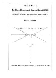
SCHWARZBECK MESS - ELEKTRONIK<br />
An der Klinge 29 D-69250 Schönau Tel.: 06228/1001 Fax.: (49)6228/1003<br />
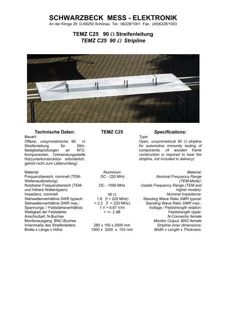
<strong>TEMZ</strong> <strong>C25</strong> 90 Ω Streifenleitung<br />
<strong>TEMZ</strong> <strong>C25</strong> 90 Ω Stripline<br />
Technische Daten: <strong>TEMZ</strong> <strong>C25</strong> Specifications:<br />
Bauart:<br />
Offene, unsymmetrische 90 Ω<br />
Type:<br />
Open, unsymmetrical 90 Ω stripline<br />
Streifenleitung für Störfestigkeitsprüfungen<br />
for automotive immunity testing of<br />
an KFZ-<br />
components. (A wooden frame<br />
Komponenten. (Verwindungssteife<br />
Holzunterkonstruktion erforderlich,<br />
construction is required to bear the<br />
stripline, not included in delivery)<br />
gehört nicht zum Lieferumfang)<br />
Material: Aluminium Material:<br />
Frequenzbereich, nominell (TEM-<br />
Wellenausbreitung):<br />
DC - 220 MHz<br />
Nominal Frequency Range<br />
(TEM-Mode):<br />
Nutzbarer Frequenzbereich (TEMund<br />
höhere Wellentypen):<br />
DC - 1000 MHz Usable Frequency Range (TEM and<br />
higher modes):<br />
Impedanz, nominell: 90 Ω Nominal Impedance:<br />
Stehwellenverhältnis SWR typisch: 1.8 (f < 220 MHz) Standing Wave Ratio SWR typical:<br />
Stehwellenverhältnis SWR max.: < 2.2 (f < 220 MHz) Standing Wave Ratio SWR max.:<br />
Spannungs- / Feldstärkeverhältnis: 1 V = 6.67 V/m Voltage / Fieldstrength relation:<br />
Welligkeit der Feldstärke: < +/- 2 dB Fieldstrength ripple:<br />
Anschlußart: N-Buchse<br />
N-Connector female<br />
Monitorausgang: BNC-Buchse<br />
Monitor Output: BNC-female<br />
Innenmaße des Streifenleiters: 280 x 150 x 2000 mm Stripline inner dimensions:<br />
Breite x Länge x Höhe: 1500 x 3200 x 153 mm Width x Length x Thickness:
SCHWARZBECK MESS - ELEKTRONIK<br />
An der Klinge 29 D-69250 Schönau Tel.: 06228/1001 Fax.: (49)6228/1003<br />
<strong>TEMZ</strong> <strong>C25</strong> 90 Ω Streifenleitung<br />
<strong>TEMZ</strong> <strong>C25</strong> 90 Ω Stripline<br />
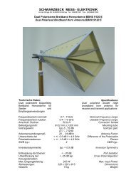
Verwendung:<br />
Die unsymmetrische 90 Ω - Streifenleitung<br />
entspricht in Ihren Abmessungen den<br />
Anforderungen aus CISPR 25 Ed3 CDV. Mit der<br />
Streifenleitung können TEM-Wellen bis max. ca.<br />
220 MHz erzeugt werden. Im TEM-Wellenbetrieb<br />
liegen im gesamten Streifenleiter sehr homogene<br />
Feldverhältnisse vor. Oberhalb von 220 MHz<br />
existieren höhere Wellentypen, bei denen eine<br />
starke Ortsabhängigkeit der Feldstärke vorliegt.<br />
Während bei TEM-Wellenanregung die<br />
Feldstärke am Rand des Streifenleiters gering ist<br />
und zur Mitte hin ansteigt, liegt bei höheren<br />
Wellentypen der umgekehrte Fall vor; man findet<br />
die höchsten Feldstärkewerte am Rande des<br />
Septums, in der Mitte liegt in der Regel ein<br />
Feldstärke-Minimum vor. Darüberhinaus sind bei<br />
hohen Frequenzen Bereiche mit veränderter<br />
Polarisationsrichtung des Feldes vorhanden. Im<br />
Grundwellenbetrieb erfolgt bei leerer Zelle nur<br />
eine sehr geringe Abstrahlung. Etwa 8 % der<br />
eingespeisten Leistung wird in die Quelle<br />
reflektiert, bedingt durch die Impedanz von 90 Ω,<br />
dies entspricht einem mittleren nominellen<br />
VSWR von 1.8. Zur Überwachung der tatsächlich<br />
vorhandenen Feldstärke eignet sich besonders<br />
das kompakte, kostengünstige netzunabhängige<br />
Feldstärkemessgerät VUFM 1670 und das LCD-<br />
Anzeigeteil VUFM 1671, die per Lichtwellenleiter<br />
verbunden sind. Zur Positionierung der Prüflinge<br />
sollten dielektrisch nahezu neutrale Werkstoffe<br />
verwendet werden, z.B. Schaumgummi oder<br />
Styroporplatten. Die Eignung eines Werkstoffes<br />
kann abgeschätzt werden, indem zunächst die<br />
Rückflußdämpfung bei leerer Zelle und<br />
anschließend mit dem zu untersuchenden<br />
Werkstoff gemessen wird. Gut geeignete<br />
Werkstoffe weisen eine minimale<br />
Dämpfungsänderung auf. Die Prüflinge sollten so<br />
gut wie möglich mittig im Streifenleiter plaziert<br />
werden. Zur Erhöhung der Reproduzierbarkeit<br />
sollte die exakte Positionierung der Prüflinge und<br />
insbesondere die Kabelführung dokumentiert<br />
werden.<br />
Application:<br />
The unsymmetrical 90 Ω stripline complies to<br />
the requirements of CISPR 25 Ed3 CDV. The<br />
stripline can be used to create TEM-waves up<br />
to max. 220 MHz. The fieldstrength<br />
distribution at TEM-mode operation inside the<br />
stripline is very homogenous. The stripline<br />
can also be used above 220 MHz, in this<br />
case higher modes do exist, which offer a<br />
location dependant fieldstrength<br />
characteristics. In contrast to the TEM-mode,<br />
where the fieldstrength is small at the edge of<br />
the stripline and increases towards the<br />
center, the higher modes show opposite<br />
characteristics: the fieldstrength is small at<br />
the center of the stripline and rises to<br />
maximum values at the edge of the strip<br />
conductor. Further the direction of<br />
polarisation changes at some areas during<br />
multi mode operation. At TEM-mode<br />
operation there are only small losses caused<br />
by radiation and dielectrical losses of the<br />
plastic support rods. Approx. 8% of the<br />
incident power is reflected back into the<br />
source due to the characteristic line<br />
impedance of 90 Ω, which corresponds to a<br />
nominal average VSWR of 1.8.<br />
An ideal tool for monitoring the actual<br />
fieldstrength inside the stripline is the VUFM<br />
1670 field meter with VUFM 1671 LCDdisplay<br />
unit, which are connected via a fibre<br />
optical link.<br />
For positioning of the EuT it is recommended<br />
to use (nearly) dielectric neutral material, e.g.<br />
foam or polystirene plastics. The suitability of<br />
the material can be checked as follows: the<br />
return loss of the empty cell is measured,<br />
then the material under test is placed in the<br />
cell and the insertion loss is measured again.<br />
Minimum differences in attenuation of the<br />
empty and loaded cell indicate a suitable<br />
material. The equipment under test (EuT)<br />
should be placed in the center of the stripline.<br />
It is recommended to record the EuT-position<br />
and the cable location as exactly as possible<br />
in order to achieve a good reproducability of<br />
the tests.
SCHWARZBECK MESS - ELEKTRONIK<br />
An der Klinge 29 D-69250 Schönau Tel.: 06228/1001 Fax.: (49)6228/1003<br />
<strong>TEMZ</strong> <strong>C25</strong> 90 Ω Streifenleitung<br />
<strong>TEMZ</strong> <strong>C25</strong> 90 Ω Stripline<br />
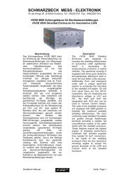
500<br />
Feldstärke und erforderliche Spannung am Abschlußwiderstand<br />
Fieldstrength and required Voltage<br />
200<br />
Fieldstrength [V/m]<br />
100<br />
50<br />
20<br />
10<br />
5<br />
1 2 5 10 20 50 100<br />
Voltage [V]
SCHWARZBECK MESS - ELEKTRONIK<br />
An der Klinge 29 D-69250 Schönau Tel.: 06228/1001 Fax.: (49)6228/1003<br />
<strong>TEMZ</strong> <strong>C25</strong> 90 Ω Streifenleitung<br />
<strong>TEMZ</strong> <strong>C25</strong> 90 Ω Stripline<br />
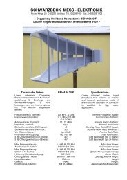
-20<br />
-25<br />
<strong>TEMZ</strong> <strong>C25</strong><br />
'h30cm.asc'<br />
'h60cm.asc'<br />
'h90cm.asc'<br />
'h120cm.asc'<br />
'h150cm.asc'<br />
'h180cm.asc'<br />
-27.5<br />
-31<br />
S21 HFS 1546 [dB]<br />
-30<br />
-35<br />
-40<br />
0 50 100 150 200 250 300 350<br />
Frequency [MHz]<br />
Feldhomogenität:<br />
Die Welligkeit der Feldstärke kann z.B. mit der<br />
aktiven Magnetfeldsonde HFS 1546 oder der<br />
aktiven E-Feldsonde EFS 9218 verifiziert<br />
werden. Mit dem 90 Ω Abschlußwiderstand ergibt<br />
sich eine maximale Welligkeit der Feldstärke<br />
über der Frequenz von +/- 2 dB an beliebigen<br />
Orten im Inneren der Leitung (Abstand vom<br />
Abschluß: 0.3 bis 1.8 m).<br />
Field Uniformity:<br />
The fieldstrength ripple can be measured with<br />
an active H-field probe (e.g. HFS 1546) or E-<br />
field probe (e.g. EFS 9218). With the supplied<br />
90 Ω termination the maximum fieldstrength<br />
ripple is within +/- 2 dB at any locations inside<br />
the cell (spacing from the termination: 0.3 to<br />
1.8 m).
SCHWARZBECK MESS - ELEKTRONIK<br />
An der Klinge 29 D-69250 Schönau Tel.: 06228/1001 Fax.: (49)6228/1003<br />
<strong>TEMZ</strong> <strong>C25</strong> 90 Ω Streifenleitung<br />
<strong>TEMZ</strong> <strong>C25</strong> 90 Ω Stripline<br />
Return Loss with 50 Ohm Termination (blue curve) and 90 Ohm Termination (green curve)<br />
0<br />
-5<br />
90 Ohm Stripline<br />
't50vswr.csv'<br />
't90vswr.csv'<br />
-10<br />
Return Loss S11 [dB]<br />
-15<br />
-20<br />
-25<br />
-30<br />
0 1e+08 2e+08 3e+08 4e+08 5e+08 6e+08 7e+08 8e+08 9e+08 1e+09<br />
Frequency [Hz]<br />
0<br />
Transmission of the stripline measured in the 50 Ohm system<br />
90 Ohm Stripline<br />
'tr.csv'<br />
-2<br />
Transmission S21 [dB]<br />
-4<br />
-6<br />
-8<br />
-10<br />
0 1e+08 2e+08 3e+08 4e+08 5e+08 6e+08 7e+08 8e+08 9e+08 1e+09<br />
Frequency [Hz]
SCHWARZBECK MESS - ELEKTRONIK<br />
An der Klinge 29 D-69250 Schönau Tel.: 06228/1001 Fax.: (49)6228/1003<br />
<strong>TEMZ</strong> <strong>C25</strong> 90 Ω Streifenleitung<br />
<strong>TEMZ</strong> <strong>C25</strong> 90 Ω Stripline<br />
Return Loss with 50 Ohm Termination (blue curve) and 90 Ohm Termination (green curve)<br />
0<br />
-5<br />
90 Ohm Stripline<br />
't50vswr.csv'<br />
't90vswr.csv'<br />
-10<br />
Return Loss S11 [dB]<br />
-15<br />
-20<br />
-25<br />
-30<br />
1e+06 1e+07 1e+08 1e+09<br />
Frequency [Hz]<br />
0<br />
Transmission of the stripline measured in the 50 Ohm system<br />
90 Ohm Stripline<br />
'tr.csv'<br />
-2<br />
Transmission S21 [dB]<br />
-4<br />
-6<br />
-8<br />
-10<br />
1e+06 1e+07 1e+08 1e+09<br />
Frequency [Hz]