SCHWARZBECK
SCHWARZBECK
SCHWARZBECK

Create successful ePaper yourself
Turn your PDF publications into a flip-book with our unique Google optimized e-Paper software.
An der Klinge 29<br />
D-69250 Schönau / Germany<br />
Tel.: +49 6228 1001<br />
<strong>SCHWARZBECK</strong><br />
Mess - Elektronik<br />
Fax.:<br />
e-mail:<br />
Web:<br />
+49 6228 1003<br />
office@schwarzbeck.de<br />
www.schwarzbeck.de<br />
List of offered calibration services<br />
Measurands<br />
The most important measurands which can be calibrated in our calibration laboratory according to ISO<br />
17025 are:<br />
• Antenna factor k<br />
• Antenna gain g<br />
• E-field strength<br />
• H-field strength<br />
• VSWR<br />
• Impedance<br />
• Attenuation<br />
• Voltage<br />
• Current<br />
• Power<br />
Frequency range<br />
Traceability to DKD standards is provided from DC to 40 GHz. We choose a suitable number of<br />
frequency points. The points will be so close to each other that interpolation errors become insignificant.<br />
For an order it is not necessary (but possible) to instruct frequency steps. In principle all antennas and<br />
devices are calibrated in the maximum possible frequency range.<br />
Uncertainty<br />
The achievable measurement uncertainty depends on the calibration method, frequency range and on<br />
the calibration object and method. It is designated in each calibration certificate.<br />
Shipment<br />
Please choose packaging material which is suitable for the return shipment, too. In case you need any<br />
advice on how to ship we gladly help you to find a reasonable way of transport. We also collect very<br />
urgent calibration orders or larger quantities of items unpacked at your site if required.<br />
Scope of delivery<br />
With any calibrated item you receive:<br />
• An ISO17025 compliant certificate of calibration with all essential information, and numerical<br />
calibration data or a graph respectively on paper.<br />
• Electronic calibration data by E-mail on request.<br />
• In case of re-calibration a calibration label as a reference between the calibration object and the<br />
certificate.<br />
Calibration intervals<br />
Usually we do not indicate calibration intervals on our certificates or labels. The calibration intervals have<br />
to be determined by the user under consideration of the individual conditions of application.<br />
Facts that require close calibrations intervals<br />
Equipment in multi level design with active<br />
components and complex electronics.<br />
Frequent use<br />
Frequent location changes<br />
Many different users<br />
Humidity, variations in temperature, vibrations<br />
Highly automated measurement system without<br />
continuous supervision.<br />
No plausibility check by independent method<br />
Staff with low technical knowledge or personnel<br />
just trained on one method<br />
Facts for longer calibrations intervals<br />
Passive equipment with uncomplex design<br />
Only intermittent use<br />
Fixed installation at one location<br />
Just one user<br />
Laboratory conditions<br />
Visual inspection of the measurement system<br />
before, during and after the measurement<br />
Plausibility check by independent method<br />
Staff with high technical knowledge and<br />
outstanding experience<br />
Antenna calibration<br />
Page 1 of 6
An der Klinge 29<br />
D-69250 Schönau / Germany<br />
Tel.: +49 6228 1001<br />
<strong>SCHWARZBECK</strong><br />
Mess - Elektronik<br />
Fax.:<br />
e-mail:<br />
Web:<br />
+49 6228 1003<br />
office@schwarzbeck.de<br />
www.schwarzbeck.de<br />
The calibration of broad band antennas is usually performed under quasi free space conditions<br />
according to SAE ARP-958. Pure antenna data is supplied. Influence of the measurement site or by<br />
reflections must be avoided. A reflected ray can add to the direct ray in a way that it increases or<br />
decreases the field strength of the direct ray depending on the phase difference between the 2 rays.<br />
From a metrological point of view this should be avoided. The data supplied by us minimizes the<br />
influence of the measurement site. Quasi free space data is independent of polarization or measurement<br />
height.<br />
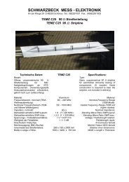
The influence of a moving phase center such as at a log.-per.-antenna is taken into account during the<br />
calibration. A log.-per. antenna radiates from the tip for the high frequencies and from the end for the low<br />
frequencies. The effective distance to the test item changes with frequency. As it is not feasible to<br />
change the distance between DuT and antenna with frequency we can calibrate the antenna for a fixed<br />
distance (e.g. 3 m) referring to a fixed reference point (e.g. antenna tip or antenna center). The data<br />
supplied in this case can directly be applied for the calculation of the field strength at a fix distance from<br />
the antenna without taking any additional uncertainty caused by the phase center shift into account.<br />
In contrast to 1 m or 3 m data we can also deliver far field data. If the distance between the antenna and<br />
the DuT is by far larger than the length of the antenna the influence of the phase center shift becomes<br />
negligible. The antenna can be considered as small compared to the measurement distance. Such data<br />
is called far field data. If far field antenna factors are used to calculate the field strength in a short<br />
distance additional uncertainty by the phase center shift must be taken into account. The shorter the<br />
distance and the longer the antenna the higher the uncertainty contribution will be.<br />
New equipment<br />
Basically new equipment is supplied in a condition that allows precise measurements. The antenna<br />
factor or correction value which is necessary for that purpose is delivered automatically without further<br />
surcharges. If technically required individual calibration data is automatically supplied. If this is<br />
technically not required or reasonable typical calibrations data is provided.<br />
Here an example: The electrical characteristics of a log.-per-antenna depend essentially on its geometry.<br />
At a frequency of 100 MHz the wavelength is approximately 3 m. So an antenna element of a log.-per<br />
antenna for this frequency would be about 750 mm long. It can be manufactured with an accuracy of<br />
0,05 mm. That means that the mechanical fabrication tolerance is about 0,0006 dB.<br />
The uncertainty that can be reached during an antenna factor calibration is in the range of approx. 0,5 –<br />
1,5 dB. In such a constellation the antenna will be supplied with typical data. Of course the antenna<br />
factor of such an antenna is checked prior to delivery. It will only be delivered if the data indicated in the<br />
manual matches with the delivered antenna. If due to formal requirements an individual calibration of<br />
such an antenna is required a discount of 30 % on the calibration prices listed below is applied. The<br />
discount is just valid for new antennas, i.e. the antenna and calibration have to be ordered at the same<br />
time.<br />
Other antennas or equipment are always delivered with individual calibrations, e.g. because the<br />
wavelength is only in the range of a few mm, or active semiconductors with varying electrical properties<br />
are built in., or material characteristics vary. In such cases an individual calibration will be supplied –<br />
without additional surcharges and without an extra order.<br />
Calibration prices for antennas:<br />
In the calibration price table below the most frequently requested measurement distances and<br />
reference points are proposed. Other reference points and distances can be selected without<br />
additional charges. In this case please clearly indicate this in your order.<br />
Ref. number Description Examples<br />
CAL BIC<br />
1ST SET UP<br />
CAL LOG<br />
1ST SET UP<br />
CAL LOG<br />
2ND SET UP<br />
Calibration of a biconical antenna. Quasi free<br />
space antenna factor and gain. First test<br />
distance: far field, reference point: center of the<br />
bicone antenna.<br />
Calibration of a log.-per. antenna. Quasi free<br />
space antenna factor and gain. First test<br />
distance: 3 m, reference point: center of the<br />
log.-per. antenna.<br />
Calibration of a log.-per. antenna. Quasi free<br />
space antenna factor and gain. Further test<br />
distance: 1 m, reference point: tip of the log.-<br />
VHA 9103 B w. BBA 9106,<br />
UBAA 9114 w. BBUK 9139,<br />
VUBA 9117, SBA 9119, HK116,<br />
POD16, POD618, EMCO 9104C,<br />
3109, VBA 6106A, SAS-540<br />
VULP 9118 A, USLP 9143,<br />
VUSLP 9111, HL223, HL040,<br />
EMCO 3148 B, 3144, 3147, UPA<br />
6108, 6109, SAS-512<br />
VULP 9118 A, USLP 9143,<br />
VUSLP 9111, HL223, HL040,<br />
EMCO 3148 B, 3144, 3147, UPA<br />
Page 2 of 6
An der Klinge 29<br />
D-69250 Schönau / Germany<br />
Tel.: +49 6228 1001<br />
<strong>SCHWARZBECK</strong><br />
Mess - Elektronik<br />
Fax.:<br />
e-mail:<br />
Web:<br />
+49 6228 1003<br />
office@schwarzbeck.de<br />
www.schwarzbeck.de<br />
CAL HYBR<br />
1ST SET UP<br />
CAL HYBR<br />
2ND SET UP<br />
CAL HORN<br />
1ST SET UP<br />
CAL HORN<br />
2ND SET UP<br />
CAL ROD<br />
CAL LOG<br />
SPIRAL<br />
CAL DIPOLE<br />
FIRST<br />
CAL DIPOLE<br />
FURTHER<br />
CAL UHA 9125 D<br />
CAL VHAP/UHAP<br />
CAL EFS 9218<br />
per. antenna.<br />
Calibration of a hybrid or Biconilog or Logbicon<br />
antenna. Quasi free space antenna factor and<br />
gain. First test distance: 3 m, reference point:<br />
center of the hybrid antenna.<br />
Calibration of a hybrid or Biconilog or Logbicon<br />
antenna. Quasi free space antenna factor and<br />
gain. Further test distance: 10 m reference<br />
point: center of the hybrid antenna.<br />
Calibration of a horn antenna. Quasi free space<br />
antenna factor and gain. First test distance: 1<br />
m, reference point: front plane of the horn<br />
antenna.<br />
Calibration of a horn antenna. Quasi free space<br />
antenna factor and gain. Further test distance: 3<br />
m, reference point: front plane of the horn<br />
antenna.<br />
Calibration of the antenna factor of an active<br />
rod antenna with calibration adapter. (Distance<br />
not applicable)<br />
Calibration of a conical log.-spiral antenna.<br />
Quasi free space antenna factor and gain. First<br />
test distance: 1 m, reference point: tip of the<br />
log.-spiral antenna.<br />
Calibration of gain and antenna factor of a half<br />
wave dipole for the first frequency. The element<br />
length is tuned to the first required frequency.<br />
Calibration of gain and antenna factor of a half<br />
wave dipole for further frequencies. The<br />
element length is tuned to the related frequency<br />
each time.<br />
Calibration of gain and antenna factor of a half<br />
wave dipole UHA 9125 D with 6 sets of fixed<br />
length elements. Settings for total element<br />
length LE and short: LE: 140 mm Short:<br />
Removed.<br />
LE: 114 mm, Short: Removed.<br />
LE: 90 mm Short: 45 mm.<br />
LE: 72 mm Short: 36 mm.<br />
LE: 60 mm Short: 30 mm.<br />
LE: 48 mm Short: 24 mm.<br />
Calibration of gain and antenna factor for a pair<br />
of 2 antennas measured in a calibration<br />
adapter, frequency range: 30-300 MHz or, 300-<br />
1000 MHz.<br />
Calibration of the antenna factor of an EFS<br />
9218 in a Crawford cell.<br />
6108, 6109, SAS-512<br />
VULB 9168, VULB 9163, CBL<br />
6111, 6112, 6141, R&S HL562,<br />
EMCO 3142, SAS-521<br />
VULB 9168, VULB 9163, CBL<br />
6111, 6112, 6141, R&S HL562,<br />
EMCO 3142, SAS-521<br />
BBHA 9120 D, BBHA 9120 E,<br />
EMCO 3106, 3115, 3116, 3117,<br />
R&S HF907,<br />
BBHA 9120 D, BBHA 9120 E,<br />
EMCO 3106, 3115, 3116, 3117,<br />
R&S HF907<br />
VAMP 9240, VAMP 9243, EMCO<br />
3301, R&S HFH2-Z1, HFH2-Z6<br />
HLX 0810, CLSA 0110, EMCO<br />
3101, 3102, 3103<br />
VHA 9103, UHA 9105, UHA<br />
9125 C, VDA 6116A, EMCO<br />
3121D<br />
VHA 9103, UHA 9105, UHA<br />
9125 C, VDA 6116A, EMCO<br />
3121D<br />
UHA 9125 D<br />
VHAP, UHAP, R&S HZ-12, HZ-<br />
13<br />
EFS 9218<br />
CAL VUFM Calibration of an electric field probe VUFM 1670<br />
(eventually with LCD unit VUFM 1671 or GPIB<br />
unit VUFM 1672). At 10 MHz we calibrate 15<br />
different field strength levels that are produced<br />
by a TEM cell.<br />
CAL 9122<br />
LW MW KW<br />
Calibration of a HFBA 9122 with elements in a<br />
range 100 kHz to 30 MHz in a TEM cell.<br />
VUFM 1670, VUFM 1671, VUFM<br />
1672<br />
HFBA 9122<br />
CAL MAG LOOP<br />
RX<br />
Calibration of the magnetic antenna factor and<br />
the fictitious electric field antenna factor of an<br />
Rx loop.<br />
FMZB 1516, HFH2-Z2, HLA<br />
6120, EMCO 6502<br />
Page 3 of 6
An der Klinge 29<br />
D-69250 Schönau / Germany<br />
Tel.: +49 6228 1001<br />
<strong>SCHWARZBECK</strong><br />
Mess - Elektronik<br />
Fax.:<br />
e-mail:<br />
Web:<br />
+49 6228 1003<br />
office@schwarzbeck.de<br />
www.schwarzbeck.de<br />
CAL HFS HMDA<br />
CAL FESP<br />
CAL HHS<br />
CAL<br />
HFCD HXYZ<br />
CAL DAF BIC<br />
CAL DAF LOG<br />
CAL SITE REF<br />
CAL CROSS<br />
POLAR<br />
CAL VSWR<br />
CAL PATTERN<br />
FIRST<br />
CAL PATTERN<br />
FURTHER<br />
Calibration of a magnetic field probe like HMDA<br />
1545, FMZB 15xx series or HFS 1546 in a<br />
calibration adapter or in a TEM cell.<br />
Calibration of a monitor loop: The conversion<br />
factor from magnetic field strength to voltage<br />
across 50 Ohm is determined. For a radiating<br />
loop the conversion factor from current to<br />
magnetic field strength in a certain distance is<br />
determined.<br />
Calculation of the conversion factor from<br />
current to magnetic field (coil factor) in the<br />
center of a square or circular pair of Helmholtz<br />
coils if the geometry is known. Additionally<br />
measurement of the coil factor.<br />
Calibration of the conversion factor in dBOhm<br />
of the transmission between a calibration dipole<br />
and a large 3 dimensional van Veen loop<br />
antenna acc. EN 55016-1-4:2007 + A1:2008<br />
C.4 for 3 perpendicular directions.<br />
Calibration of the Dual antenna factor of a pair<br />
of biconical antennas acc. to the 2-antennamethod.<br />
The sum of the antenna factors of the<br />
pair is determined and divided by 2. Test<br />
distance: 3 m between the centers of the<br />
biconical antennas. Quasi free space<br />
conditions.<br />
Calibration of the Dual antenna factor of a pair<br />
of log.-per.-antennas acc. to the 2-antennamethod.<br />
The sum of the antenna factors of the<br />
pair is determined and divided by 2. Test<br />
distance: 3 m between the centers of the log.-<br />
per.-antennas. Quasi free space conditions.<br />
Calibration of the site reference based on the<br />
antenna combination of a small biconical<br />
antenna as Tx and a hybrid antenna as Rx<br />
antenna 30-1000 MHz in a distance of 3 m form<br />
the center of the hybrid antenna for validation of<br />
a fully anechoic chamber acc. to CISPR16-1-4.<br />
Calibration of the cross polarisation rejection<br />
and the internal cross polarisation decoupling of<br />
a dual polarized antenna.<br />
Calibration of the VSWR at the antenna<br />
connector.<br />
Recording the directional pattern of an antenna<br />
in E-plane and H-plane for the first frequency.<br />
Recording the directional pattern of an antenna<br />
for any further frequency.<br />
HMDA 1545, FMZB 1538, HFS<br />
1546<br />
FESP 5133, FESP 5132, FESP<br />
5134, FESP 5133-7/41, F-304,<br />
F-305, 7605, 7606<br />
HHS 5204-36, HHS 5204-12,<br />
HHS 5215, HHS 5218, 6402,<br />
6404<br />
HXYZ 9170, HFCD 9171,<br />
HM020, HM020Z3,<br />
RF-300<br />
A pair of VHBB 9124 with BBA<br />
9106, a pair of HK116<br />
A pair of VULP 9118 A, A pair of<br />
VUSLP 9111<br />
UBAA 9114 or UBAA 9115 w.<br />
elements BBUK 9139 with VULB<br />
9168 or VULB 9163 or CBL 6111<br />
or EMCO 3142 or HL562<br />
XSLP 9142, VULX 9163, XSLP<br />
9143, BBHX 9120 E, BBHX 9120<br />
LF, 3164-05, 3164-06, 3164-08<br />
All antennas and many other<br />
devices<br />
SBA 9112, SBA 9113, SBA<br />
9119, POD16, POD618<br />
SBA 9112, SBA 9113, SBA<br />
9119, POD16, POD618<br />
Calibration prices for conducted measurands<br />
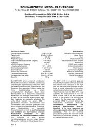
Cal BBV Calibration of the gain of a broadband<br />
preamplifier.<br />
BBV 9742, BBV 9718, PAM-<br />
0118, TS-PR1, TS-PR3, TS-PR7<br />
CAL CABLE Calibration of the attenuation of a coaxial cable<br />
or an attenuator.<br />
AK 9513, AK 9515 G, Sucoflex<br />
104, RG223<br />
CAL VTSD Calibration of the attenuation of a pulse limiter. VTSD 9561 F, VTSD 9561 D,<br />
PL-01, ESH3-Z2<br />
CAL SY 9501 Calibration of the attenuation between 2 ea SY SY 9501<br />
9501<br />
CAL TK Calibration of the insertion loss of a HF voltage TK 9420, SHC, ESH2-Z3<br />
probe<br />
CAL V-LISN 1 Calibration of the magnitude of the impedance NSLK 8127, ENV216, ESH3-Z5,<br />
Page 4 of 6
An der Klinge 29<br />
D-69250 Schönau / Germany<br />
Tel.: +49 6228 1001<br />
<strong>SCHWARZBECK</strong><br />
Mess - Elektronik<br />
Fax.:<br />
e-mail:<br />
Web:<br />
+49 6228 1003<br />
office@schwarzbeck.de<br />
www.schwarzbeck.de<br />
CAL V-LISN 2<br />
CAL ISN 1<br />
CAL ISN 2<br />
at DuT terminals (BNC terminated with 50 Ohm)<br />
and calibration of the transmission from the DuT<br />
terminals to BNC according to EN 55016-1-<br />
2:2004 + A1:2005.<br />
Additionally to CAL V-LISN 1: Calibration of the<br />
phase of the impedance at DuT terminals and<br />
calibration of the isolation between mains<br />
terminals and DuT terminals or BNC connector<br />
respectively acc. to EN 55016-1-2:2004 +<br />
A2:2006.<br />
Transmission EuT to BNC, AE to BNC @ EuT<br />
open, AE to BNC @ EuT shorted. Common<br />
mode (asymmetrical) impedance at EuT<br />
terminals, BNC terminated with 50 Ohm.<br />
Longitudinal Conversion Loss LCL at the EuT<br />
Terminals<br />
NSLK 8126, ESH2-Z5, NSLK<br />
8128, ENV4200, NNLK 8129,<br />
NNLK 8130, NNBM 8125, NNBM<br />
8126 D, ESH3-Z6, NNBL 8226<br />
NSLK 8127, ENV216, ESH3-Z5,<br />
NSLK 8126, ESH2-Z5, NSLK<br />
8128, ENV4200, NNLK 8129,<br />
NNLK 8130<br />
NTFM 8131, NTFM 8132, NTFM<br />
8136<br />
NTFM 8132, NTFM 8136<br />
CAL CDN Z Calibration of the impedance of a CDN. L801M2, L801AF2,L 801S8<br />
CAL CDN K Calibration of the k-factor of a CDN additionally L801M2, L801AF2, L801S8<br />
to its impedance.<br />
CAL EM 101<br />
ATT/DECOU<br />
Calibration of an EM 101: Attenuation N-<br />
connector-EuT-cable and decoupling (absorber<br />
EM 101, F-2031, KEMZ 801<br />
effectiveness).<br />
CAL CVP Calibration of the insertion loss of a capacitive CVP 9222, CVP 2200<br />
voltage probe CVP 9222.<br />
CAL SW Calibration of the transfer impedance or the SW 9602, SW 9605, F-33-2, EZinsertion<br />
loss of a current clamp.<br />
17<br />
CAL FTC 101 Calibration of the insertion loss in a 50 Ohm FTC-101<br />
System in a jig<br />
CAL IGLK/IGU Calibration of an IGLK 2914 or IGU 2912. IGU 2912, IGLK 2914<br />
CAL IGUF Calibration of an IGUF 2910. IGUF 2910<br />
CAL IGUU Calibration of a pulse generator IGUU 2916. IGUU 2916, IGUU 2918<br />
Output level of the main and aux.-generator<br />
across 50 Ohm at Quasi peak detection in all<br />
bands.<br />
CAL KU 9616 Calibration of the attenuation of a KU 9616 or a<br />
KU 9618.<br />
CAL MDS 1 Calibration of the insertion loss acc. to CISPR<br />
16-1-3 Ed. 2.0 in large jig with secondary<br />
absorbing device and calculation of the Clamp<br />
Factor CForig, which is finally needed for<br />
correction purposes during disturbance power<br />
measurements. Please send the MDS 21, the<br />
coaxial cable and the 6 dB attenuator. The<br />
attenuation of cable and attenuator will then be<br />
taken into account.<br />
CAL MDS 22 Calibration of the insertion loss in the calibration<br />
jig.<br />
CAL MG Calibration of the output level of a tracking<br />
generator vs. frequency.<br />
CAL REC A,B Calibration of an EMI receiver Band A and B.<br />
Calibration of the available detectors Quasi<br />
Peak, Peak, Average, CAV and CRMS at sine<br />
or pulse signals. Step attenuator calibration,<br />
passband selectivity and random noise.<br />
CAL REC C,D,E Calibration of an EMI receiver Band C and D<br />
(and E). Calibration of the available detectors<br />
Quasi Peak, Peak, Average, CAV and CRMS at<br />
sine or pulse signals. Step attenuator<br />
calibration, passband selectivity and random<br />
noise.<br />
KU 9616, KU 9618<br />
MDS 21, Kyoritsu KT-10, AMZ<br />
41A<br />
MDS 22<br />
MG 1522<br />
FCKL 1528, ESH2<br />
FCVU 1534, ESV<br />
Page 5 of 6
An der Klinge 29<br />
D-69250 Schönau / Germany<br />
Tel.: +49 6228 1001<br />
<strong>SCHWARZBECK</strong><br />
Mess - Elektronik<br />
Fax.:<br />
e-mail:<br />
Web:<br />
+49 6228 1003<br />
office@schwarzbeck.de<br />
www.schwarzbeck.de<br />
CAL REC<br />
A,B,C,D,E<br />
CAL SG<br />
Calibration of an EMI receiver Band A, B, C, D<br />
and E. Calibration of the available detectors<br />
Quasi Peak, Peak, Average, CAV and CRMS at<br />
sine or pulse signals. Step attenuator<br />
calibration, passband selectivity and random<br />
noise.<br />
Calibration of the voltage level across 50 Ohm<br />
of a spectrum generator SG 9301.<br />
FCLE 1535, ESCS30<br />
SG 9301, SG 9302<br />
Page 6 of 6