Technische Hinweise zu den Video-Audio-Modulatoren ... - Spaun
Technische Hinweise zu den Video-Audio-Modulatoren ... - Spaun
Technische Hinweise zu den Video-Audio-Modulatoren ... - Spaun
Erfolgreiche ePaper selbst erstellen
Machen Sie aus Ihren PDF Publikationen ein blätterbares Flipbook mit unserer einzigartigen Google optimierten e-Paper Software.
Byk-Gul<strong>den</strong>-Str. 22 • D-78224 Singen<br />
Telefon: +49 (0) 7731 - 86730 • Telefax: +49 (0) 7731 - 64202<br />
e-mail: info@spaun.de • www.spaun.de<br />
<strong>Technische</strong> <strong>Hinweise</strong><br />
<strong>zu</strong> <strong>den</strong> <strong>Video</strong>-<strong>Audio</strong>-<strong>Modulatoren</strong><br />
• VAM 220 NF<br />
• VAM 420 NF<br />
!<br />
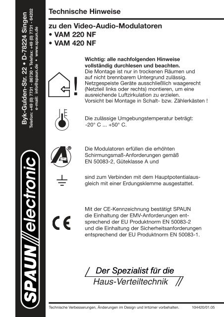
Wichtig: alle nachfolgen<strong>den</strong> <strong>Hinweise</strong><br />
vollständig durchlesen und beachten.<br />
Die Montage ist nur in trockenen Räumen und<br />
auf nicht brennbarem Untergrund <strong>zu</strong>lässig.<br />
Netzgespeiste Geräte ausschließlich waagerecht<br />
(Netzteil links oder rechts) montieren, um eine<br />
ausreichende Luftzirkulation <strong>zu</strong> erzielen.<br />
Vorsicht bei Montage in Schalt- bzw. Zählerkästen !<br />
Die <strong>zu</strong>lässige Umgebungstemperatur beträgt:<br />
-20° C ... +50° C.<br />
Die <strong>Modulatoren</strong> erfüllen die erhöhten<br />
Schirmungsmaß-Anforderungen gemäß<br />
EN 50083-2, Güteklasse A und<br />
sind <strong>zu</strong>m Verbin<strong>den</strong> mit dem Hauptpotentialausgleich<br />
mit einer Erdungsklemme ausgestattet.<br />
Mit der CE-Kennzeichnung bestätigt SPAUN<br />
die Einhaltung der EMV-Anforderungen entsprechend<br />
der EU Produktnorm EN 50083-2<br />
und die Einhaltung der Sicherheitsanforderungen<br />
entsprechend der EU Produktnorm EN 50083-1.<br />
<strong>Technische</strong> Verbesserungen, Änderungen im Design und Irrtümer vorbehalten. 104420/01.05
TM<br />
!<br />
Wichtig: alle nachfolgen<strong>den</strong> <strong>Hinweise</strong> vollständig<br />
durchlesen und beachten !<br />
Die Montage ist nur in trockenen Räumen <strong>zu</strong>lässig. Auf ausreichende<br />
Luftzirkulation achten.<br />
Erdung nach Vorschrift anbringen.<br />
Die <strong>Audio</strong>- und <strong>Video</strong>signale entsprechend der<br />
Gerätebeschriftung <strong>zu</strong>führen.<br />
Fernspeisung:<br />
Zu versorgende externe Systeme<br />
( z.B. <strong>Video</strong>kamera ) an außenliegende Klemme<br />
anschließen.<br />
Versorgungsspannung und max. Stromabgabe<br />
beachten!<br />
VAM ... NF mit dem terrestrischen Antennen-<br />
Verteilnetz verbin<strong>den</strong>.<br />
Nicht benutzten Eingang terminieren !<br />
Kanalwahlschalter auf Kanal 00 einstellen<br />
( Testbildaktivierung ).<br />
Erst jetzt die Netzverbindung herstellen !
TM<br />
Inbetriebnahme:<br />
Ausgangskanal ( K21 ... K69 ) einstellen.<br />
Nichtnachbarkanaltauglichkeit beachten !<br />
Ausgangskanal prüfen und einpegeln.<br />
Testbild:<br />
Der integrierte Testbildgenerator generiert zwei<br />
weiße Balken als Einstellhilfe.<br />
1.<br />
2.<br />
Reset-Funktion:<br />
1. Testbild deaktivieren:<br />
Netzverbindung trennen !<br />
2.<br />
Netzverbindung wieder herstellen:<br />
Modulator im Normalbetrieb.<br />
<strong>Audio</strong>-Pegel angleichen.<br />
Inbetriebnahme ist abgeschlossen.<br />
Ergänzender Hinweis:<br />
Ausschalten des Modulators:<br />
Kanal < 21 bzw.<br />
Kanal > 69 einstellen.
<strong>Technische</strong> Daten / Technical data:<br />
Typ / Type<br />
Anzahl der <strong>Video</strong>- / <strong>Audio</strong>-Eingänge<br />
No. of video- / audio- inputs<br />
VAM 220 NF<br />
je 1 each<br />
VAM 420 NF<br />
je 2 each<br />
<strong>Video</strong> / <strong>Video</strong>:<br />
Eingangsimpedanz / Input impedance<br />
Spannung / Nominal voltage<br />
Polarität / Polarity<br />
<strong>Audio</strong> (Mono) / <strong>Audio</strong> (mono):<br />
Eingangsimpedanz / Input impedance<br />
Spannung für Vollaussteuerung<br />
Input voltage for max. dev. ( 0 dB )<br />
Preemphase / Preemphasis<br />
Frequenzbereich / Frequency range<br />
Lautstärke-Stellbereich / Volume adjustment<br />
Modulator (PLL-Synthesizer) / Modulator:<br />
Fernsehnorm / TV standard<br />
Frequenzbereich / Frequency range<br />
Kanäle / Channels<br />
Kanalwahl / Channel selection<br />
Testbildgenerator / Test pattern generator<br />
Ausschaltmöglichkeit<br />
Modulator turn-off<br />
Max. Ausgangspegel / Max. outputlevel<br />
Pegelstellbereich / Level adjustment range<br />
Störprodukte außerhalb des Kanals<br />
Spurious outside channel<br />
Störprodukte innerhalb des Kanals<br />
Spurious inside channel<br />
<strong>Video</strong> Signal-Rauschverhältnis / <strong>Video</strong> S/N ratio<br />
<strong>Audio</strong>-Klirrfaktor / <strong>Audio</strong> THD<br />
<strong>Audio</strong> Signal-Rauschverhältnis / <strong>Audio</strong> S/N ratio<br />
HF-Durchschleifeingang / RF loop through:<br />
Frequenzbereich / Frequency range<br />
Durchgangsdämpfung / Through loss<br />
Impedanz / Impedance<br />
HF-Anschlüsse / RF terminals<br />
Stromversorgung / Mains power:<br />
Nennspannung / Nominal voltage<br />
Spannungsbereich / Voltage range<br />
Max. Leistungsaufnahme / Max. power consumption<br />
Max. Stromabgabe über außenliegende Klemme<br />
<strong>zu</strong>r Versorgung z.B. einer <strong>Video</strong>-Kamera<br />
Remote power provided ( via external termial )<br />
Abmessungen / Dimensions<br />
75 W / BNC female<br />
U pp = 1 V<br />
Synchronpegel negativ / negative going sync.<br />
10 kW (unsymmetrisch unbalanced / BNC female)<br />
U rms = 0,63 V<br />
50 µs<br />
40 Hz ... 15 kHz<br />
-12 dB je -12 dB each<br />
PAL / G<br />
470 ... 862 MHz<br />
K 21 ... K 69 / nicht nachbarkanaltauglich<br />
E 21 ... E 69 / Double sideband modulator<br />
über Drehschalter / rotary switches<br />
eingebaut / implemented<br />
Kanäle < 21 bzw. > 69 einstellen<br />
select a channel < 21 or > 69<br />
95 ± 3 dBµV<br />
-18 dB je -18 dB each<br />
60 dBc<br />
58 dBc<br />
50 dB bewertet / weighted<br />
0,5 %<br />
50 dB<br />
47 ... 862 MHz<br />
1,5 dB 2 dB<br />
75 W ( 18 dB -1,5 dB / Oktave / octave )<br />
F-Connectoren DC-fest / DC-blocked ( max. 50 V DC )<br />
AC: 100-240 V / 50-60 Hz<br />
AC: 92-265 V / 47-63 Hz<br />
9,5 W 12,5 W<br />
+ 12 V / 350 mA<br />
293 x 125 x 75 mm
Byk-Gul<strong>den</strong>-Str. 22 • D-78224 Singen<br />
Telephone: +49 (0) 7731 - 86730 • Fax: +49 (0) 7731 - 64202<br />
e-mail: info@spaun.de • www.spaun.de<br />
Technical Instructions<br />
for the <strong>Video</strong>-<strong>Audio</strong>-Modulators<br />
• VAM 220 NF<br />
• VAM 420 NF<br />
Important: Please observe the following instructions !<br />
Installation is only permitted in dry rooms and upon<br />
a non-combustible surface. Ensure that there is<br />
adequate air circulation. Wall mounting only with<br />
power supply housing at left or right side of the<br />
device (horizontal mounting).<br />
The permissible ambient temperature<br />
range is: -20° C ... +50° C (253 K ... 323 K).<br />
The modulators meet the more stringent<br />
screening requirements according to<br />
EN 50083-2, quality grade A.<br />
All components are equipped with an earthing<br />
terminal for connecting to the main potential<br />
equalization.<br />
SPAUN electronic confirms the keeping of the<br />
EMC requirements in accordance to the EU product<br />
norm EN 50083-2 and the keeping of the safety<br />
requirements in accordance to the EU product<br />
norm EN 50083-1 by the CE sign.<br />
The C-Tick mark shows the conformity of the device<br />
with the EMC regulations of the ACA.<br />
(ACA requirements bases on CISPR, CENELEC and<br />
IEC standards).<br />
Specifications and design are subject to change due<br />
to our policity of continual technical improvement. 104420/01.05
TM<br />
!<br />
It is important to read this manual completely.<br />
Do not mount the devices in humid places.<br />
Allow adequate ventilation.<br />
Connect ground according to the local regulations.<br />
Connect video- and audio signals as shown on<br />
the label.<br />
Remote power provided:<br />
Connect remote powered devices (e.g. camera)<br />
to external terminals.<br />
Note the value of voltage and max. remote current.<br />
Connect the VAM ... NF to the MATV / CATV<br />
system.<br />
Terminate input if unused.<br />
Select channel 00<br />
(activates test pattern generator).<br />
Apply mains power.
TM<br />
Select output channel ( E21 ... E69 ).<br />
Note that the channel below the selected is not<br />
usable due to the use of double sideband modulator.<br />
Check the output channel and adjust the level<br />
accordingly.<br />
Test pattern:<br />
The internal test pattern generator creates two<br />
white bars to ease tuning.<br />
1.<br />
2.<br />
Reset function:<br />
To deactivate the test signal pull and re-plug<br />
power cord.<br />
Device starts up in standard mode.<br />
Adjust audio level accordingly.<br />
Installation is complete.<br />
Additional information:<br />
To turn off a modulator select a channel below<br />
E21 or above E69.


