290.116 Berg-ssk-SeriesGrippers.indd - TAC Rockford
290.116 Berg-ssk-SeriesGrippers.indd - TAC Rockford
290.116 Berg-ssk-SeriesGrippers.indd - TAC Rockford

Sie wollen auch ein ePaper? Erhöhen Sie die Reichweite Ihrer Titel.
YUMPU macht aus Druck-PDFs automatisch weboptimierte ePaper, die Google liebt.
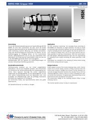
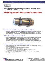
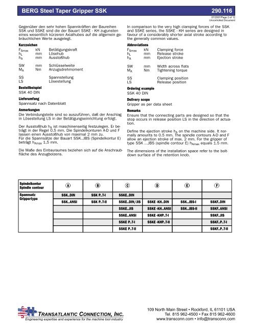
BERG Steel Taper Gripper SSK <strong>290.116</strong><br />
Gegenüber den sehr hohen Spannkräften der Baureihen<br />
SSK und SSKE sind die der Bauart SSKE - KH zugunsten<br />
eines wesentlich kürzeren Axialhubes auf die allgemein gebräuchlichen<br />
Werte ausgelegt.<br />
Kurzzeichen<br />
F Smax kN Betätigungskraft<br />
h L mm Lösehub<br />
h A mm Ausstoßhub<br />
07/2007/Page 2 of 12<br />
Uncontrolled Document<br />
In comparison to the very high clamping forces of the SSK<br />
and SSKE series, the SSKE - KH series are designed in<br />
favour of a considerably shorter axial stroke according to<br />
the generally common values.<br />
Abbreviations<br />
F Smax kN Clamping force<br />
h L mm Release stroke<br />
h A mm Ejection stroke<br />
SW mm Schlüsselweite<br />
M A Nm Anzugsdrehmoment<br />
SS<br />
Spannstellung<br />
LS<br />
Lösestellung<br />
Bestellbeispiel<br />
SSK 40 DIN<br />
Lieferumfang<br />
Spannsatz nach Datenblatt<br />
Anmerkungen<br />
Die Verbindungsteile sind so auszuführen, daß der Anschlag<br />
in Lösestellung LS in der Betätigungseinrichtung erfolgt.<br />
Der Ausstoßhub h A ist maschinenseitig festzulegen. Er beträgt<br />
in der Regel 0,5 mm. Die Spindelkonturen A-D und F<br />
lassen einen Ausstoßhub von maximal 2 mm zu.<br />
Für die Spannsätze der Bauart SSK..JBS (Spindelkontur E)<br />
beträgt h Amax 1,5 mm.<br />
Die Maße des Einbauraumes beziehen sich auf die Anschraubfläche<br />
des Anzugbolzens.<br />
SW mm Width across flats<br />
M A Nm Tightening torque<br />
SS<br />
Clamping position<br />
LS<br />
Release position<br />
Ordering example<br />
SSK 40 DIN<br />
Delivery scope<br />
Gripper as per data sheet<br />
Remarks<br />
Ensure that the connecting parts are designed so that the<br />
stop occurs in release position LS in the direction of actuation.<br />
Define the ejection stroke h A on the machine side. It normally<br />
amounts to 0.5 mm. The spindle contours A-D and F<br />
allow an ejection stroke of max. 2 mm. For the gripper of<br />
type SSK ...JBS (spindle contour E) h Amax equals 1.5 mm.<br />
The dimensions of the installation space refer to the boltdown<br />
surface of the retention knob.<br />
Spindelkontur<br />
Spindle contour<br />
Spannsatz<br />
Grippertype<br />
A B C D E<br />
SSK..DIN<br />
SSK..ANSI<br />
SSK P..T-I<br />
SSK P..T-II<br />
SSKE..DIN<br />
SSKE..DIN/JIS<br />
SSKE..JIS<br />
SSKE..ANSI<br />
SSKE P..T-I<br />
SSKE P..T-II<br />
SSKE -KH..DIN<br />
SSKE -KH..ANSI<br />
SSKE -KHP..T-I<br />
SSKE -KHP..T-II<br />
SSK..JBS-I<br />
SSK..JBS-II<br />
F<br />
SSKF..DIN<br />
SSKF..ANSI<br />
SSKF..JIS<br />
SSKF..P..T-I<br />
SSKF..P..T-II<br />
29