BERG SSK Gripper Installation Instructions - TAC Rockford
BERG SSK Gripper Installation Instructions - TAC Rockford
BERG SSK Gripper Installation Instructions - TAC Rockford

Create successful ePaper yourself
Turn your PDF publications into a flip-book with our unique Google optimized e-Paper software.
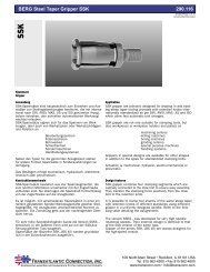
<strong>BERG</strong> <strong>SSK</strong> Standard Taper <strong>Gripper</strong> <strong>Installation</strong> <strong>Instructions</strong> 100.320<br />
122706/Page 1 of 2<br />
Uncontrolled Document<br />
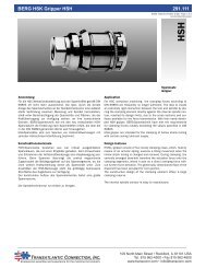
1. Design Recommendations<br />
• The design should allow the gripper to be removed/installed into a clamping system from the front [spindle side].<br />
• We suggest securing all connections with removable locking compound [with one exception – see next point],<br />
such as Loctite 638 or equivalent in accordance with manufacturer instructions.<br />
• The mounting thread for the gripper itself should not be secured with locking compound. During final installation<br />
the gripper should be securely torqued with a hex wrench per the following chart:<br />
<strong>Gripper</strong> Size #30 Taper #40 Taper #45 Taper #50 Taper #60 Taper<br />
Socket Wrench Size 6 mm 8 mm 8 mm 10 mm 17 mm<br />
<strong>Installation</strong> Torque<br />
30 Nm<br />
22 ft. lb.<br />
65 Nm<br />
49 ft. lb.<br />
110 Nm<br />
83 ft. lb.<br />
160 Nm<br />
120 ft. lb.<br />
450 Nm<br />
338 ft. lb.<br />
For adjustment to proper gage dimension during installation we recommend using a spacer between the drawbar rod<br />
and the gripper. This spacer is available from Transatlantic Connection, Inc. and is to be cut to proper length after<br />
measuring the gage dimension. See reverse for gage dimensions.<br />
2. <strong>Installation</strong> Recommendations<br />
A gage dimension is generally shown on the <strong>BERG</strong> proposal drawing for a drawbar system. The gage dimension<br />
is the required length between the face of the spindle [gage diameter] and the gripper body face in the un-clamped<br />
position. For proper operation of the clamping system this dimension is critical and must be correct.<br />
It is also a good practice to check the actual clamping force [pull force] of the drawbar system with a pull force gage<br />
when installation is completed. Contact Transatlantic Connection, Inc. for information on available pull force gages.<br />
We also recommend checking the gage dimension and the clamping force after installation and operating the system<br />
for a few hours. Loose connections, etc may cause variations from the original setting.<br />
3. Spindle Speed Recommendations and Limitations<br />
For <strong>BERG</strong> <strong>Gripper</strong>s Style <strong>SSK</strong> and <strong>SSK</strong>E<br />
For <strong>BERG</strong> <strong>Gripper</strong> Style <strong>SSK</strong>S and <strong>SSK</strong>ES<br />
Taper Size 10: n max. = 100,000 RPM [High Speed Version]<br />
Taper Size 15: n max. = 80,000 RPM<br />
Taper Size 20: n max. = 70,000 RPM<br />
Taper Size 25: n max. = 60,000 RPM<br />
Taper Size 30: n max. = 15,000 RPM Taper Size 30: n max. = 50,000 RPM<br />
Taper Size 40: n max. = 10,000 RPM Taper Size 40: n max. = 30,000 RPM<br />
Taper Size 45: n max. = 8,000 RPM Taper Size 45: n max. = 22,000 RPM<br />
Taper Size 50: n max. = 7,000 RPM Taper Size 50: n max. = 20,000 RPM<br />
Taper Size 60: n max. = 5,000 RPM Taper Size 60: n max. = 12,000 RPM<br />
Note: The above spindle speeds are empirical values based on experience. Criteria for the above speeds are acceptable<br />
runout at these speeds, vibration, and achievable spindle speeds used in the machine tool industry. For higher<br />
spindle speeds contact Transatlantic Connection, Inc.<br />
4. Maximum Allowable Clamping Force of Drawbar System<br />
Taper Size 30: 2,000 lb<br />
Taper Size 40: 4,000 lb<br />
Taper Size 45: 5,600 lb<br />
Taper Size 50: 7,500 lb<br />
Taper Size 60: 15,600 lb<br />
Note: Proper Clamping Force plays an important role in machine performance, service life, and safety. The force<br />
can be directed using the ForceCheck clamping force gage. Contact us for more information.
<strong>BERG</strong> <strong>SSK</strong> Standard Taper <strong>Gripper</strong> <strong>Installation</strong> <strong>Instructions</strong> 100.320<br />
Gage Dimensions for <strong>Gripper</strong>s:<br />
122706/Page 2 of 2<br />
Uncontrolled Document<br />
Tool Ejected = LS<br />
Tool Clamped = SS<br />
Stroke for Ejection = h A<br />
Kontrollmaß L<br />
Gage Dimension L<br />
Setting dimension L<br />
Note: The gage dimensions are recommended by <strong>BERG</strong>. A spindle Manufacturer may decide on a different gage<br />
dimension. Consult the Spindle Manufacturer for appropriate dimensions.<br />
Collet<br />
Tool Taper<br />
MAS 403-1982<br />
Gage Dimension<br />
check depth<br />
Tool Taper<br />
ISO 7388/1<br />
L +0.2<br />
and CAT<br />
ANSI B 5.50<br />
L +0.3<br />
-0.0 -0.0<br />
Gage Dimension<br />
check depth<br />
<strong>SSK</strong>(S) 30/1DIN<br />
<strong>SSK</strong>E(S) 30DIN<br />
<strong>SSK</strong>(S) 30/1ANSI<br />
<strong>SSK</strong>E(S) 30 ANSI<br />
<strong>SSK</strong>E(S) P30T-I(II)<br />
BT30<br />
71.5<br />
71.5<br />
59.1<br />
59.1<br />
70.5<br />
#30<br />
70.8<br />
70.8<br />
58.4<br />
58.4<br />
69.8<br />
<strong>SSK</strong>(S) 40DIN<br />
<strong>SSK</strong>E(S) 40DIN<br />
<strong>SSK</strong>(S) 40ANSI<br />
<strong>SSK</strong>E(S) 40 ANSI<br />
<strong>SSK</strong>(S) P40T-I(II)<br />
<strong>SSK</strong>E(S) P40T-I(II)<br />
BT40<br />
90.5<br />
90.5<br />
80.7<br />
80.7<br />
99.5<br />
99.5<br />
#40<br />
93.4<br />
93.4<br />
83.6<br />
83.6<br />
102.4<br />
102.4<br />
<strong>SSK</strong>(S) 45DIN<br />
<strong>SSK</strong>E(S) 45DIN<br />
<strong>SSK</strong>(S) 45ANSI<br />
<strong>SSK</strong>E(S) 45 ANSI<br />
<strong>SSK</strong>(S) P45T-I(II)<br />
<strong>SSK</strong>E(S) P45T-I(II)<br />
BT45<br />
111.8<br />
111.8<br />
102.65<br />
102.65<br />
121.8<br />
121.8<br />
#45<br />
111.6<br />
111.6<br />
102.45<br />
102.45<br />
121.6<br />
121.6<br />
<strong>SSK</strong>(S) 50DIN<br />
<strong>SSK</strong>E(S) 50DIN<br />
<strong>SSK</strong>(S) 50ANSI<br />
<strong>SSK</strong>E(S) 50 ANSI<br />
<strong>SSK</strong>(S) P50T-I(II)<br />
<strong>SSK</strong>E(S) P50T-I(II)<br />
BT50<br />
134.8<br />
134.8<br />
126.15<br />
126.15<br />
145.8<br />
145.8<br />
#50<br />
134.65<br />
134.65<br />
126<br />
126<br />
145.65<br />
145.65<br />
Dimensions are in mm, based on 0.5 mm knockout stroke. Dimensions are based on <strong>BERG</strong> Data Sheet T1251<br />
8/03/93.