Arcam A70 amplifier Amplificateur Arcam A70 Arcam ... - MR Hifi
Arcam A70 amplifier Amplificateur Arcam A70 Arcam ... - MR Hifi
Arcam A70 amplifier Amplificateur Arcam A70 Arcam ... - MR Hifi

Sie wollen auch ein ePaper? Erhöhen Sie die Reichweite Ihrer Titel.
YUMPU macht aus Druck-PDFs automatisch weboptimierte ePaper, die Google liebt.
Using your <strong>A70</strong> <strong>amplifier</strong><br />
<br />
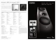
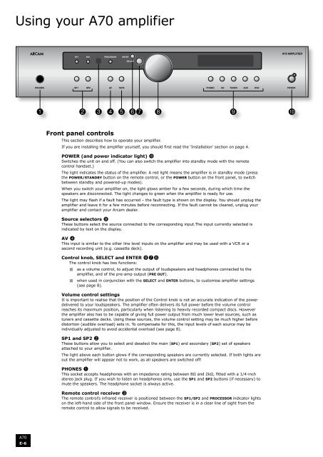
Front panel controls<br />
This section describes how to operate your <strong>amplifier</strong>.<br />
If you are installing the <strong>amplifier</strong> yourself, you should first read the ‘Installation’ section on page 4.<br />
POWER (and power indicator light) bk<br />
Switches the unit on and off. (You can also switch the <strong>amplifier</strong> into standby mode with the remote<br />
control handset.)<br />
The light indicates the status of the <strong>amplifier</strong>. A red light means the <strong>amplifier</strong> is in standby mode (press<br />
the Power/Standby button on the remote control, or the POWER button on the front panel, to switch<br />
between standby and powered-up modes).<br />
When you switch your <strong>amplifier</strong> on, the light glows amber for a few seconds, during which time the<br />
speakers are disconnected. The light changes to green when the <strong>amplifier</strong> is ready for use.<br />
The light may flash if a fault has occurred – the fault type is shown on the display. You should unplug the<br />
<strong>amplifier</strong> and leave it for a few minutes before reconnecting. If the fault cannot be cleared, unplug your<br />
<strong>amplifier</strong> and contact your <strong>Arcam</strong> dealer.<br />
Source selectors 9<br />
These buttons select the source connected to the corresponding input.The input currently selected is<br />
indicated by text on the display.<br />
AV 4<br />
This input is similar to the other line level inputs on the <strong>amplifier</strong> and may be used with a VCR or a<br />
second recording unit (e.g. cassette deck).<br />
Control knob, SELECT and ENTER 876<br />
The control knob has two functions:<br />
< as a volume control, to adjust the output of loudspeakers and headphones connected to the<br />
<strong>amplifier</strong>, and of the pre-amp output (PRE OUT).<br />
< when used in conjunction with the SELECT and ENTER buttons, to customise <strong>amplifier</strong> settings<br />
(see page 8).<br />
Volume control settings<br />
It is important to realise that the position of the Control knob is not an accurate indication of the power<br />
delivered to your loudspeakers. The <strong>amplifier</strong> often delivers its full power before the volume control<br />
reaches its maximum position, particularly when listening to heavily recorded compact discs. However<br />
the <strong>amplifier</strong> also has to be capable of giving full power output from much lower level sources, such as<br />
tuners and cassette decks. Using these sources, the volume control setting may be much higher before<br />
distortion (audible overload) sets in. To compensate for this, the input levels of each source may be<br />
individually adjusted to avoid accidental overload (see page 8).<br />
SP1 and SP2 2<br />
These buttons allow you to select and deselect the main (SP1) and secondary (SP2) set of speakers<br />
attached to your <strong>amplifier</strong>.<br />
The light above each button glows if the corresponding speakers are currently selected. If both lights are<br />
out the <strong>amplifier</strong> will appear not to work, as all speakers are switched off!<br />
PHONES 1<br />
This socket accepts headphones with an impedance rating between 8Ω and 2kΩ, fitted with a 1/4-inch<br />
stereo jack plug. If you wish to listen on headphones only, use the SP1 and SP2 buttons (if necessary) to<br />
mute the speakers. The headphone socket is always active.<br />
Remote control receiver 3<br />
The remote control’s infrared receiver is positioned between the SP1/SP2 and PROCESSOR indicator lights<br />
on the left-hand side of the front panel window. Ensure the receiver is in a clear line of sight from the<br />
remote control to allow signals to be received.<br />
<strong>A70</strong><br />
E-6