Maschinentechnische Neuerungen bei Mix- schild- und ... - Tunnel
Maschinentechnische Neuerungen bei Mix- schild- und ... - Tunnel
Maschinentechnische Neuerungen bei Mix- schild- und ... - Tunnel

Sie wollen auch ein ePaper? Erhöhen Sie die Reichweite Ihrer Titel.
YUMPU macht aus Druck-PDFs automatisch weboptimierte ePaper, die Google liebt.
30 TBM-Technologie TBM Technology <strong>Tunnel</strong> 8/2009<br />
<strong>Maschinentechnische</strong><br />
<strong>Neuerungen</strong> <strong>bei</strong> <strong>Mix</strong><strong>schild</strong>-<br />
<strong>und</strong> EPB-Technik<br />
für 2 Großprojekte in<br />
Skandinavien<br />
Dr. M. Herrenknecht, Dr. Karin Bäppler, W. Burger<br />
Im Fokus des Beitrags, der anlässlich der<br />
STUVA-Tagung 2009 in Hamburg präsentiert<br />
wurde, stehen maschinentechnische<br />
<strong>Neuerungen</strong> im Bereich der <strong>Mix</strong><strong>schild</strong>- <strong>und</strong><br />
EPB-Technik. Vorgestellt werden die<br />
<strong>Neuerungen</strong> am Beispiel zweier Großprojekte in<br />
Skandinavien, die auf den jeweiligen<br />
Projektanforderungen <strong>und</strong> Vortriebserfahrungen<br />
basieren <strong>und</strong> nun als Stand der<br />
Technik einzustufen sind.<br />
Engineering Innovations<br />
for <strong>Mix</strong>-Shield and EPB<br />
Technology for two<br />
major Projects in<br />
Scandinavia<br />
Dr. M. Herrenknecht, Dr. Karin Bäppler, W. Burger<br />
The report concentrates on engineering<br />
innovations in conjunction with mix-shield and<br />
EPB technology. It was presented at the 2009<br />
STUVA Conference in Hamburg. These<br />
innovations are displayed on the basis of two<br />
major projects in Scandinavia, which are<br />
fo<strong>und</strong>ed on the given project requirements and<br />
experiences gained during tunnelling, which<br />
can now be categorised as state of the art.<br />
Dr. E.h. Martin Herrenknecht,<br />
Vorstandsvorsitzender,<br />
Herrenknecht AG, Schwanau/D<br />
Dr.-Ing. Karin Bäppler,<br />
Herrenknecht AG, Schwanau/D<br />
Dipl.-Ing. Werner Burger,<br />
Herrenknecht AG, Schwanau/D<br />
schnitten <strong>und</strong> zunehmend auch<br />
höhere Gr<strong>und</strong>wasserdrücke definieren<br />
gr<strong>und</strong>sätzlich die Realisierbarkeit<br />
maschineller <strong>Tunnel</strong>vortriebe.<br />
Erfordernisse<br />
über Tage (dichte innerstädtische<br />
Bebauung, beengte Platzverhältnisse<br />
an Start- <strong>und</strong> Zielschacht)<br />
bestimmen <strong>bei</strong> immer<br />
mehr Projekten die Auslegung<br />
von Vortriebsanlagen <strong>und</strong> stellen<br />
Herausforderungen an die<br />
Baustellenlogistik.<br />
Die zukunftsweisenden Infrastrukturprojekte<br />
verlangen<br />
nach einer ausgereiften <strong>und</strong><br />
stets an die wachsenden Erfordernisse<br />
angepassten Maschinentechnik.<br />
So finden z. B. die<br />
<strong>Mix</strong><strong>schild</strong>e sowohl in ihrer klassischen<br />
Betriebsart als Schild<br />
mit flüssigkeitsgestützter Ortsbrust,<br />
als auch als Schild mit<br />
wechselnder Betriebsart, ein<br />
breiter werdendes Anwendungs-<br />
Two trends have become<br />
discernible in the development<br />
of mechanised tunnel driving<br />
technology in recent years: firstly<br />
demands on the engineering<br />
technology have risen significantly.<br />
Secondly ever more<br />
complex challenges have to be<br />
mastered regarding the technical<br />
and logistical aspects of<br />
projects.<br />
Essentially the feasibility of<br />
mechanised tunnel driving is<br />
governed by the subsoil conditions<br />
as well as long tunnel<br />
routes given major tunnel crosssections<br />
and ever more frequently<br />
even greater gro<strong>und</strong>water<br />
pressures. Surface requirements<br />
(densely built-up<br />
inner urban areas, constricted<br />
space conditions at the access<br />
and target shafts) determine<br />
the design of tunnelling installations<br />
for an increasing number<br />
In der Entwicklung der maschinellen<br />
<strong>Tunnel</strong>vortriebstechnik<br />
haben sich in den vergangenen<br />
Jahren 2 Tendenzen herausgebildet:<br />
Zum einen sind<br />
die Anforderungen an die Maschinentechnik<br />
signifikant gestiegen.<br />
Zum anderen sind in<br />
den Projekten immer komplexere<br />
baugr<strong>und</strong>technische <strong>und</strong><br />
logistische Herausforderungen<br />
zu bewältigen.<br />
Die Baugr<strong>und</strong>verhältnisse<br />
sowie vor allem lange <strong>Tunnel</strong>trassen<br />
<strong>bei</strong> großen <strong>Tunnel</strong>querof<br />
projects and pose challenges<br />
on the construction site logistics.<br />
These future-oriented infrastructural<br />
projects call for mature<br />
engineering technology<br />
that is adapted to growing demands.<br />
Thus mix-shields both in<br />
their classical operating mode<br />
as a shield with fluid-supported<br />
face as well as a shield with alternating<br />
operating mode, are<br />
<strong>bei</strong>ng used for an ever increasing<br />
range of applications. This<br />
type of machine has turned out<br />
Dr. E. h. Martin Herrenknecht,<br />
CEO, Herrenknecht AG,<br />
Schwanau/D<br />
Dr.-Ing. Karin Bäppler,<br />
Herrenknecht AG, Schwanau/D<br />
Dipl.-Ing. Werner Burger,<br />
Herrenknecht AG, Schwanau/D
32 TBM-Technologie TBM Technology <strong>Tunnel</strong> 8/2009<br />
gebiet. Dieser Maschinentyp erweist<br />
sich aufgr<strong>und</strong> seines<br />
Maschinenkonzepts als Generalist<br />
für Projekte mit hohen<br />
Anforderungen. Hierzu parallel<br />
haben auch die Erdruck<strong>schild</strong>e<br />
durch den Einsatz der Schaumkonditionierung<br />
eine Erweiterung<br />
ihres Einsatzbereichs erfahren<br />
<strong>und</strong> damit nach Projekterfolgen<br />
in Fernost auch in<br />
Europa eine erhebliche Verbreitung<br />
gef<strong>und</strong>en. Gegenwärtig<br />
werden Erddruck<strong>schild</strong>e auch<br />
<strong>bei</strong> heterogenen Baugr<strong>und</strong>verhältnissen<br />
(Locker- <strong>und</strong> Festgestein)<br />
eingesetzt.<br />
Infrastrukturprojekte<br />
in Skandinavien<br />
In Skandinavien sind derzeit<br />
2 der größten Infrastrukturprojekte<br />
im Bau. Es handelt sich<br />
hier<strong>bei</strong> um den Citytunnel<br />
Malmö <strong>und</strong> den Eisenbahntunnel<br />
Hallandsas in Schweden.<br />
Der Citytunnel Malmö ist ein<br />
Eisenbahninfrastrukturprojekt,<br />
mit dem neben der verbesserten<br />
Anbindung des schwedischen<br />
Eisenbahnnetzes an das gesamteuropäische<br />
Hochgeschwindigkeitsnetz<br />
auch eine bessere<br />
Anbindung von Malmö an die<br />
Öres<strong>und</strong>brücke <strong>und</strong> damit an<br />
die Metropolregion Kopenhagen<br />
geschaffen wird. Das Citytunnel-<br />
Projekt umfasst eine 17 km<br />
lange Eisenbahnstrecke, wovon<br />
zwei 4,6 km lange eingleisige<br />
<strong>Tunnel</strong>röhren im Rahmen des<br />
größten Bauloses E 201 dieses<br />
Projektes mit maschineller<br />
<strong>Tunnel</strong>vortriebstechnik aufgefahren<br />
wurden.<br />
Für den Eisenbahntunnel<br />
Hallandsas an der Westküste<br />
Schwedens werden 2 parallele<br />
Röhren von 8,6 km aufgefahren.<br />
Der <strong>Tunnel</strong> ist Teil der Verbindungsstrecke<br />
Malmö– Göteborg,<br />
die zur Hochgeschwindigkeitsstrecke<br />
ausgebaut werden<br />
soll. Im Einsatz hierfür ist<br />
ein <strong>Mix</strong><strong>schild</strong>, das vom offenen<br />
Hartgesteinsmodus ohne Druck<br />
auf einen geschlossenen flüssigkeitsgestützten<br />
Modus umgestellt<br />
werden kann.<br />
Die für diese <strong>bei</strong>den Großprojekte<br />
zum Einsatz kommende<br />
Maschinentechnik muss<br />
komplexen baugr<strong>und</strong>technischen<br />
<strong>und</strong> logistischen Herausforderungen<br />
gerecht werden.<br />
Entsprechend wurden bzw.<br />
werden die <strong>Tunnel</strong>vortriebsanlagen<br />
einem ständigen Optimierungsprozess<br />
unterzogen,<br />
um auch zukünftige Bauvorhaben<br />
mit projektspezifisch angepasster<br />
Maschinentechnik sicher<br />
<strong>und</strong> effizient bewältigen zu<br />
können.<br />
Citytunnel Malmö<br />
Der zweiröhrige Citytunnel<br />
Malmö hat eine Gesamtlänge<br />
von rd. 6 km <strong>und</strong> verbindet die<br />
Eisenbahntrasse aus Dänemark<br />
über die Öres<strong>und</strong>brücke kommend<br />
mit dem Hauptbahnhof<br />
der Stadt Malmö <strong>und</strong> dem skandinavischen<br />
Eisenbahnnetz. Das<br />
Gesamtprojekt besteht aus<br />
4 Einzellosen E 101, E 201,<br />
E 301 <strong>und</strong> E 302. Im Rahmen<br />
des größten Bauloses E 201 des<br />
Projektes Citytunnel Malmö<br />
wurden 2 parallele eingleisige<br />
<strong>Tunnel</strong>röhren von 4,6 km Länge<br />
mit 2 <strong>Tunnel</strong>bohrmaschinen<br />
aufgefahren.<br />
Der Auftrag für die Planung<br />
<strong>und</strong> Ausführung des Bauloses<br />
E 201 wurde im Jahr 2004 an<br />
die Ar<strong>bei</strong>tsgemeinschaft „Malmö<br />
Citytunnel Group“ (MCG) unter<br />
der Federführung des deutschen<br />
Unternehmens Bilfinger<br />
Berger AG, Mannheim <strong>und</strong><br />
2 dänischen Firmen, Per Aarsleff<br />
A/S <strong>und</strong> E. Phil & Son A.S. erteilt.<br />
Die <strong>bei</strong>den 4,6 km langen<br />
<strong>Tunnel</strong>röhren im Schildvortrieb<br />
mit Tübbingausbau haben einen<br />
Innendurchmesser von 7,90 m.<br />
Der Abstand zwischen den<br />
Röhren variiert zwischen 10<br />
<strong>und</strong> 30 m. Des Weiteren <strong>bei</strong>nhaltet<br />
der Auftrag für das Teil-<br />
Los E 201 eine 390 m lange<br />
Rampe, einen 360 m langen<br />
to be a multi-purpose weapon<br />
for projects posing high demands<br />
by dint of its engineering<br />
concept. Parallel to this EBP<br />
shields have extended their<br />
range of applications thanks to<br />
the introduction of foam conditioning<br />
and have gained in popularity<br />
following successful<br />
projects in the Far East in Europe<br />
as well. At present EPB shields<br />
are also <strong>bei</strong>ng used for heterogeneous<br />
subsoil conditions.<br />
Infrastructural<br />
Projects in<br />
Scandinavia<br />
Currently 2 major infrastructural<br />
projects are <strong>bei</strong>ng built in<br />
Scandinavia: the Malmö Citytunnel<br />
and the Hallandsas rail<br />
tunnel in Sweden.<br />
The Malmö Citytunnel is a<br />
railway infrastructural project<br />
that provides Malmö with a better<br />
link to the Öres<strong>und</strong> Bridge<br />
and in turn with the Copenhagen<br />
metropolitan region quite<br />
apart from connecting the<br />
Swedish railway network more<br />
satisfactorily to the entire pan-<br />
European high-speed system.<br />
The Citytunnel project embraces<br />
a 17 km long railway route including<br />
two 4.6 km long tunnel<br />
tubes within the scope of the<br />
project’s biggest contract section<br />
E 201 driven by mechanised<br />
tunnelling technology.<br />
Two 8.6 km long parallel<br />
tubes are excavated for the<br />
Hallandsas rail tunnel on Sweden’s<br />
west coast. The tunnel<br />
constitutes a part of the line<br />
connecting Malmö with Göteborg,<br />
which is to be developed<br />
as a high-speed route. A mixshield<br />
is used for this purpose,<br />
which can be converted from<br />
open hard rock mode without<br />
pressure to a closed fluid-supported<br />
system.<br />
The engineering technology<br />
applied for these two major<br />
projects must master complex<br />
subsoil technical and logistical<br />
challenges. Towards this end<br />
the tunnelling installations were<br />
and still are subject to a constant<br />
optimisation process so<br />
that future construction projects<br />
can also be tackled safely<br />
and efficiently with engineering<br />
technology adapted to the specific<br />
project.<br />
Malmö Citytunnel<br />
The twin-bore Malmö<br />
Citytunnel is altogether some 6<br />
km long and links the rail route<br />
from Denmark approaching via<br />
the Öres<strong>und</strong> Bridge with Malmö<br />
Central Station and the Scandinavian<br />
railway network. The<br />
overall project consists of 4 individual<br />
contract sections E 101,<br />
E 201, E 301 and E 302. Within<br />
the scope of the biggest contract<br />
section E 201 of the Malmö<br />
Citytunnel project two 4.6 km<br />
long parallel single-track tubes<br />
were excavated with 2 tunnel<br />
boring machines.<br />
The contract for planning<br />
and executing contract section<br />
E 201 was awarded in 2004 to<br />
the “Malmö Citytunnel Group”<br />
(MCG) JV <strong>und</strong>er the leadership<br />
of the German company<br />
Bilfinger Berger AG, Mannheim<br />
and 2 Danish companies, Per<br />
Aarsleff and E. Phil & Son A.S.<br />
The two shield-driven 4.6 km<br />
long tubes with segmental lining<br />
possess a 7.90 m internal diameter.<br />
The gap between the<br />
tubes varies from 10 to 30 m.<br />
The contract for sub-section<br />
E201 also involves a 390 m long<br />
ramp, a 360 m long cut-andcover<br />
tunnel, the “Triangeln” station<br />
(280 m), 4 pressure compensation<br />
shafts and 2 emergency<br />
exit shafts as well as<br />
13 cross-passages.<br />
The construction of the parallel<br />
bores created by mechanised<br />
tunnel driving is dealt<br />
with in particular.<br />
The tubes were driven at a<br />
depth varying from roughly 20<br />
to 25 m. The prevailing formations<br />
consist of a 6 to 12 m thick<br />
quaternary covering layer set
<strong>Tunnel</strong> 8/2009 Innovations for <strong>Mix</strong>-Shield and EPB<br />
33<br />
Cut-and-Cover-<strong>Tunnel</strong>, den<br />
Bahnhof „Triangeln“ (280 m),<br />
4 Druckausgleichschächte <strong>und</strong><br />
2 Notausstiegschächte sowie<br />
13 Querschläge.<br />
Im Besonderen wird auf den<br />
Bau der mit maschineller<br />
<strong>Tunnel</strong>vortriebstechnik erstellten<br />
parallelen <strong>Tunnel</strong>röhren eingegangen.<br />
Die Röhren wurden in einer<br />
Tiefe von etwa 20 bis 25 m aufgefahren.<br />
Die anstehenden Formationen<br />
umfassen eine 6 bis<br />
12 m dicke quartäre Deckschicht<br />
auf einem ca. 60 m<br />
mächtigen Schichtpaket aus tertiären<br />
Kalken. Diese weisen<br />
stark unterschiedliche Festigkeiten<br />
auf. Der Grenzbereich<br />
zwischen Deckschicht <strong>und</strong> dem<br />
Fels wurde als angewittert <strong>und</strong><br />
somit stark Wasser führend<br />
charakterisiert.<br />
Eingesetzt wurden 2 auf die<br />
Geologie abgestimmte baugleiche,<br />
je 120 m lange Erddruck<strong>schild</strong>e<br />
mit einem Durchmesser<br />
von 8,89 m. Die Maschinen waren<br />
auf die in Malmö anstehenden<br />
Gr<strong>und</strong>wasserdrücke von<br />
bis zu 2,0 bar ausgelegt. Ende<br />
November 2006 startete der<br />
erste Schild von der Station<br />
„Holma“ <strong>bei</strong> km 5+320 zum<br />
Ziel „Malmö C“ <strong>bei</strong> km 0+448;<br />
der zweite Erddruck<strong>schild</strong> nahm<br />
den Vortrieb im Januar 2007<br />
auf.<br />
Das Schneidrad wurde an die<br />
zu erwartenden geologischen<br />
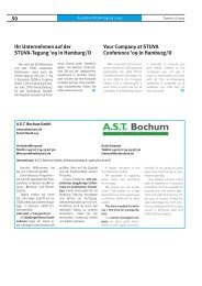
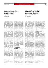
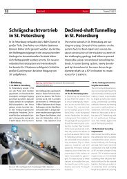
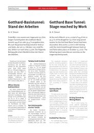
1 Durchstich Vortriebsanlage Citytunnel Malmö, EPB-Schild mit 8,89 m<br />
Durchmesser<br />
1 Breakthrough of the Citytunnel Malmö tunnelling installation, EPB shield<br />
with 8.89 m diameter<br />
Bedingungen angepasst <strong>und</strong><br />
mit einem elektrischen Antrieb<br />
ausgestattet. Es war mit<br />
124 Schälmessern, 46 Einfachdisken<br />
(17˝), 4 Doppeldisken<br />
(17˝) <strong>und</strong> 16 Räumern bestückt.<br />
Alle Werkzeuge sind von<br />
der Rückseite des Schneidrades<br />
aus sicher <strong>und</strong> effizient wechselbar.<br />
Nach einem Vortrieb von<br />
2,7 km bis zur Station Triangeln<br />
erreichte die erste Maschine<br />
nach 9 Monaten ihr erstes<br />
Etappenziel. In der Station<br />
„Triangeln“ wurde die Maschine<br />
durch die 280 m lange Station<br />
gezogen <strong>und</strong> dort überholt, um<br />
die restlichen 1,9 km in Richtung<br />
Zielschacht „Malmö C“<br />
(Malmö Central, Hauptbahnhof)<br />
on a roughly 60 m thick zone of<br />
tertiary limestones, which possess<br />
varying thicknesses. The<br />
border area between the covering<br />
layer and the rock was characterised<br />
as weathered and thus<br />
strongly water-bearing.<br />
Two identical EPB shields,<br />
each 120 m long with 8.89 m<br />
diameter and geared to the geology<br />
were applied. The machines<br />
were devised for the prevailing<br />
gro<strong>und</strong>water pressures<br />
in Malmö of up to 2.0 bar. The<br />
first shield started from<br />
“Holma” station at km 5+320 towards<br />
the target “Malmö C” at<br />
km 0+448 at the end of<br />
November 2006; the second<br />
EPB shield began excavating in<br />
January 2007.<br />
The cutting wheel was adjusted<br />
to the expected geological<br />
conditions and fitted with an<br />
electric drive. It was equipped<br />
with 124 cutters, 46 single discs<br />
(17”), 4 double discs (17”) and<br />
16 buckets. All the tools can be<br />
replaced safely and efficiently<br />
from the rear of the cutting<br />
wheel.<br />
After excavating 2.7 km up<br />
to Triangeln station the first machine<br />
reached its first stage target<br />
after 9 months. In the<br />
“Triangeln” station the machine<br />
was pulled through the 280 m<br />
long structure and overhauled<br />
there in order to drive the remaining<br />
1.9 km towards the<br />
“Malmö C” (Malmö Central) target<br />
shaft. In March and April<br />
2008 the 2 machines reached<br />
their goal “Malmö C” with rates<br />
of advance of up to 239 m per<br />
week (Fig. 1).<br />
The tunnel with 7.90 m internal<br />
diameter was lined with<br />
watertight reinforced concrete<br />
segments. A uni-ring with a<br />
smooth annular joint and guide<br />
rods was applied in the longitudinal<br />
joints. Intermediate layers<br />
in the level annular joints and<br />
bolting of the segments in the<br />
longitudinal joints were not<br />
foreseen apart from at the keystone.<br />
The 1.8 m long segmental<br />
ring was produced using<br />
7+1 elements. The segments<br />
weigh 5 to 6 t with the keystone<br />
weighing 1 t.
34 <strong>Neuerungen</strong> <strong>bei</strong> <strong>Mix</strong><strong>schild</strong> <strong>und</strong> EPB<br />
<strong>Tunnel</strong> 8/2009<br />
aufzufahren. Im März bzw.<br />
April 2008 erreichten <strong>bei</strong>de<br />
Maschinen ihr Ziel „Malmö C“<br />
mit Vortriebsleistungen von bis<br />
zu 239 m pro Woche (Bild 1).<br />
Der <strong>Tunnel</strong> mit einem<br />
Innendurchmesser von 7,90 m<br />
wurde mit wasserdichten Stahlbetontübbingen<br />
ausgekleidet.<br />
Zur Ausführung kam ein Uni-<br />
Ring mit glatter Ringfuge <strong>und</strong><br />
Führungsstangen in den Längsfugen.<br />
Zwischenlagen in den<br />
ebenen Ringfugen <strong>und</strong> Tübbingverschraubung<br />
in den Längsfugen<br />
wurden außer am<br />
Schlussstein nicht vorgesehen.<br />
Pro Tübbingring von 1,8 m<br />
Länge wurden 7+1 Elemente zu<br />
einem Ring zusammengesetzt.<br />
Die Tübbinge haben ein Gewicht<br />
von 5 bis 6 t, der Schlussstein<br />
wiegt 1 t.<br />
Die Tübbingfabrikationsanlage<br />
wurde in Holma, gegenüber<br />
des <strong>Tunnel</strong>portals, eingerichtet.<br />
Die für die in Summe 4,6 km<br />
langen doppelröhrigen <strong>Tunnel</strong><br />
erforderlichen insgesamt<br />
13 Querschläge wurden <strong>bei</strong> laufendem<br />
TBM-Vortrieb realisiert.<br />
Im hinteren Bereich des<br />
Nachläufers werden Sohlsegmente<br />
eingebaut, die einen<br />
zweigleisigen Betrieb im <strong>Tunnel</strong><br />
ermöglichen. Während des Vortriebs<br />
besteht somit die Möglichkeit,<br />
die Querschläge zur<br />
Verbindung der <strong>bei</strong>den <strong>Tunnel</strong>röhren<br />
zu erstellen. Die Abmessungen<br />
der Elemente ermöglichten<br />
dem mittig fixierten<br />
Streckengleis auch die Aufnahme<br />
eines örtlich benötigten Ausweichgleises.<br />
Dies konnte höhengleich<br />
verschwenkt werden.<br />
Die Andienung der Maschine<br />
mit Tübbingen <strong>und</strong> Vortriebsmaterial<br />
sowie der Personentransport<br />
wurden über das Gleis<br />
organisiert.<br />
Hallandsas-<br />
Eisenbahntunnel<br />
An der schwedischen Westküste<br />
wird derzeit die Zugverbindung<br />
von Malmö nach Göteborg<br />
zu einer Hochgeschwindigkeitsstrecke<br />
ausgebaut. Der<br />
Abschluss <strong>und</strong> die Inbetriebnahme<br />
der neuen zweigleisigen<br />
Bahnverbindung für Hochgeschwindigkeitszüge<br />
wird die<br />
Fahrzeit zwischen den <strong>bei</strong>den<br />
Städten um 2 St<strong>und</strong>en verkürzen.<br />
Darüber hinaus steigt die<br />
Gesamtkapazität der Bahnverbindung<br />
von 4 Zügen pro St<strong>und</strong>e<br />
auf 24 Züge pro St<strong>und</strong>e.<br />
Eine Herausforderung entlang<br />
dieser Strecke stellt die<br />
Querung des Hallandsas-Höhenzugs<br />
südlich von Bastad dar, für<br />
die ein umbaubares <strong>Mix</strong><strong>schild</strong><br />
mit einem Durchmesser von<br />
10,6 m im Einsatz ist.<br />
Erste Versuche, den <strong>Tunnel</strong><br />
bergmännisch aufzufahren,<br />
scheiterten Mitte der 1990er<br />
The segment factory was set<br />
up in Holma across from the<br />
tunnel portal.<br />
The total of 13 cross-passages<br />
required for the altogether<br />
4.6 km long twin-tube tunnel<br />
were produced as the TBM drive<br />
progressed. Base segments<br />
were installed in the back-up’s<br />
rear zone, which enabled a twotrack<br />
operation in the tunnel.<br />
During the drive it is thus possible<br />
to create the cross-passages<br />
joining the 2 tunnel bores. The<br />
dimensions of the elements<br />
made it possible to set up a<br />
passby siding that was required<br />
locally in addition to the central<br />
track. This could be swivelled at<br />
the same height.<br />
The track ensured that the<br />
machine was supplied with segments<br />
and driving material in<br />
addition to transporting personnel.<br />
Hallandsas Railway<br />
<strong>Tunnel</strong><br />
Currently the rail link between<br />
Malmö and Göteborg is<br />
<strong>bei</strong>ng developed as a highspeed<br />
route on the Swedish<br />
west coast. When the new twintrack<br />
rail link for high-speed<br />
trains is concluded and put into<br />
service the travelling time between<br />
the 2 cities will be cut by<br />
2 hours. In addition the total capacity<br />
of the rail link will be increased<br />
from 4 to 24 trains per<br />
hour.<br />
One challenge along this<br />
route is posed by crossing the<br />
Hallandsas range to the south of<br />
Bastad, towards which end a<br />
convertible mix-shield with<br />
10.6 m diameter is <strong>bei</strong>ng applied.<br />
Initial attempts to drive the<br />
tunnel by mining means were<br />
thwarted in the mid-1990s owing<br />
to geological conditions<br />
that were difficult to master<br />
such as high water pressures<br />
and inflowing water as well as<br />
strongly fissured rock.<br />
Bids were once again invited<br />
for the project requiring a 9.4 m<br />
internal diameter for the 5.5 km<br />
long tunnel preferably using<br />
mechanised tunnelling technology.<br />
Owing to the attempts<br />
that had previously failed strict<br />
environmental requirements<br />
especially regarding the<br />
gro<strong>und</strong>water were laid down.<br />
The Swedish Central Office<br />
for Railways (Banverket) is the<br />
client for the project. A Swedish-<br />
French consortium Skanska-<br />
Vinci was awarded the contract<br />
to accomplish the project.<br />
The prevailing geological<br />
formations along the planned<br />
tunnel route mainly consist of<br />
gneiss with amphibolite intrusions.<br />
The uni-axial compressive<br />
strengths of the freshly exposed<br />
rock can be as much as 250 MPa;<br />
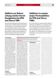
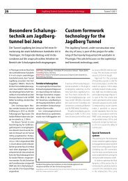
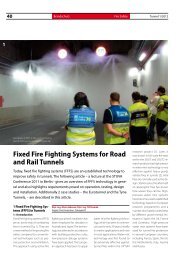
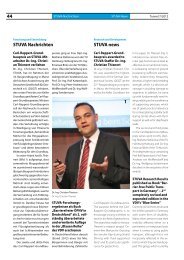
2 Dualmodus-<strong>Mix</strong><strong>schild</strong> für Hartgestein<br />
2 Dual-mode mix-shield for hard rock
<strong>Tunnel</strong> 8/2009<br />
TBM Technology<br />
Jahre an schwer zu beherrschenden<br />
geologischen Bedingungen<br />
wie hohen Wasserdrücken<br />
bzw. Zuflussmengen<br />
<strong>und</strong> teils stark zerklüftetem<br />
Gebirge.<br />
Das Projekt wurde erneut<br />
ausgeschrieben mit der Forderung<br />
nach einem Innendurchmesser<br />
des <strong>Tunnel</strong>s von 9,4 m<br />
<strong>bei</strong> einer <strong>Tunnel</strong>länge von<br />
5,5 km <strong>und</strong> dem bevorzugten<br />
Einsatz maschineller <strong>Tunnel</strong>vortriebstechnik.<br />
Aufgr<strong>und</strong> der<br />
vorangegangenen gescheiterten<br />
Versuche wurden strikte Umweltauflagen<br />
insbesondere bezüglich<br />
des Gr<strong>und</strong>wassers gemacht.<br />
Bauherr des Projektes ist<br />
das Schwedische Zentralamt für<br />
Eisenbahnwesen (Banverket).<br />
Der Zuschlag für die Realisierung<br />
des Bauvorhabens ging an das<br />
schwedisch-französische Konsortium<br />
Skanska-Vinci.<br />
Die anstehenden geologischen<br />
Formationen entlang der<br />
geplanten <strong>Tunnel</strong>trasse bestehen<br />
hauptsächlich aus Gneis mit<br />
Einschlüssen von Amphibolit.<br />
Die einaxialen Druckfestigkeiten<br />
des frisch anstehenden Felses<br />
können bis zu 250 MPa erreichen;<br />
der Cerchar Abrasivitätsindex<br />
(CAI) liegt im Allgemeinen<br />
über 4,5, wo<strong>bei</strong> Werte von bis<br />
zu 5,9 gemessen wurden. Die<br />
Gesteine werden somit als sehr<br />
abrasiv klassifiziert.<br />
Der Gr<strong>und</strong>wasserdruck auf<br />
<strong>Tunnel</strong>niveau erreicht 13 bar.<br />
Entsprechend ergeben sich die<br />
größten Herausforderungen im<br />
maschinellen Vortrieb <strong>bei</strong>m<br />
Projekt Hallandsas in Bezug auf<br />
erwartete hohe Wasserzuflüsse<br />
<strong>und</strong> auf eine gleichzeitig strikte<br />
gesetzliche Limitierung der<br />
zulässigen Entnahmemengen.<br />
Ebenso wurde das Antreffen<br />
von begrenzten Störzonen mit<br />
Lockergestein <strong>und</strong> ähnlichem<br />
Verhalten nicht ausgeschlossen.<br />
Vor diesem Hintergr<strong>und</strong><br />
wurden erste konzeptionelle<br />
Entwicklungen <strong>bei</strong> Herrenknecht<br />
auf Basis der Hauptanthe<br />
Cerchar abrasiveness index<br />
(CAI) generally lies in excess of<br />
4.5, with values of up to 5.9 recorded.<br />
As a consequence the<br />
rocks are classified as <strong>bei</strong>ng extremely<br />
abrasive.<br />
The gro<strong>und</strong>water pressure<br />
at tunnel level reaches 13 bar.<br />
Consequently the greatest challenges<br />
for mechanised driving<br />
in the case of the Hallandsas<br />
project are posed by expected<br />
high water inflows and at the<br />
same strict legal limitation of<br />
the permissible withdrawal<br />
quantities. In addition encountering<br />
limited fault zones with<br />
soft gro<strong>und</strong> and similar conditions<br />
was not precluded.<br />
Against this backgro<strong>und</strong> initial<br />
conceptional developments<br />
were <strong>und</strong>ertaken at Herrenknecht<br />
based on the main requirements<br />
dating from 1999/<br />
2000. The project at this point in<br />
time was still at the preliminary<br />
tendering phase. Technology<br />
had to adapt to the following requirements:<br />
Removal of hard and abrasive<br />
rock formations<br />
Removal of soft gro<strong>und</strong> or<br />
mixed face conditions<br />
Danger of penetration of<br />
large quantities of water along<br />
the entire tunnel route<br />
More than 10 bar static water<br />
pressure along the bulk of the<br />
tunnel route<br />
Strict (legal) environmental<br />
conditions governing the<br />
amount of inflowing water<br />
Strict environmental conditions<br />
and approval procedures<br />
for the materials and methods<br />
applied.<br />
It soon became evident that<br />
only a shield machine with<br />
sealed tunnel lining (segments)<br />
would be able to completely<br />
comply with these requirements<br />
in the event of a mechanised<br />
tunnelling solution. The<br />
TBM had to be capable of performing<br />
both in an open and<br />
closed driving mode so that the<br />
most unfavourable geological<br />
and construction technical con-
36 TBM-Technologie TBM Technology <strong>Tunnel</strong> 8/2009<br />
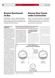
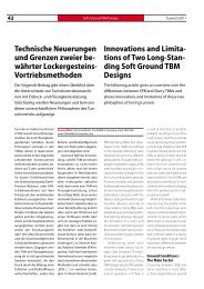
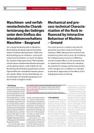
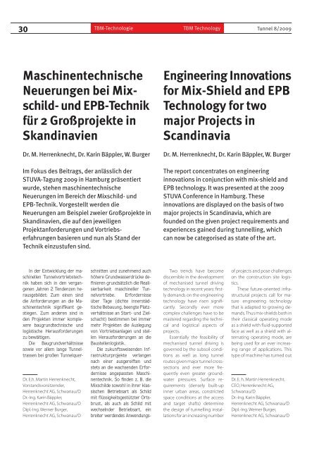
3 TBM S-246 Hallandsas in der Vormontage im Werk<br />
3 TBM S-246 Hallandsas <strong>bei</strong>ng pre-assembled at the factory<br />
forderungen im Jahre 1999/<br />
2000 vorgenommen. Das Projekt<br />
befand sich zu diesem<br />
Zeitpunkt noch in der Vor-<br />
Ausschreibungsphase. Die Technik<br />
musste auf folgende Anforderungen<br />
angepasst werden:<br />
Abbau von harten <strong>und</strong> abrasiven<br />
Felsformationen<br />
Abbau von weichem Boden<br />
oder gemischten Ortsbrustverhältnissen<br />
Gefahr des Eindringens großer<br />
Wassermengen entlang der<br />
gesamten <strong>Tunnel</strong>länge<br />
Mehr als 10 bar statischer<br />
Wasserdruck entlang des überwiegenden<br />
Anteils der <strong>Tunnel</strong>trasse<br />
Strikte (gesetzliche) Umweltauflagen<br />
hinsichtlich der Wasserzuflussmenge<br />
Strikte Umweltauflagen <strong>und</strong><br />
Genehmigungsverfahren für die<br />
verwendeten Materialien <strong>und</strong><br />
Methoden.<br />
Sehr schnell wurde deutlich,<br />
dass im Falle einer mechanisierten<br />
<strong>Tunnel</strong>vortriebslösung nur<br />
eine Schildmaschine mit abgedichteter<br />
<strong>Tunnel</strong>auskleidung<br />
(Tübbinge) diese Anforderungen<br />
vollständig erfüllen könnte.<br />
Die TBM sollte in einem offenen<br />
<strong>und</strong> auch geschlossenen Vortriebsmodus<br />
betrieben werden<br />
können, um die ungünstigsten<br />
geologischen <strong>und</strong> bautechnischen<br />
Bedingungen, wie maximale<br />
Wasserdrücke <strong>und</strong> komplexe<br />
Gebirgsbedingungen, sicher<br />
beherrschen zu können.<br />
Der flüssigkeitsgestützte Modus<br />
stellte somit die einzig mögliche<br />
Option für den geschlossenen<br />
Modus dar.<br />
Im Januar 2004 erhielt<br />
Herrenknecht den Auftrag, eine<br />
<strong>Tunnel</strong>vortriebsmaschine entsprechend<br />
den Anforderungen<br />
zu liefern (Tabelle). Unter Berücksichtigung<br />
der Tatsache,<br />
dass der Abbau im geschlossenen<br />
Modus unter hohem<br />
Druck <strong>bei</strong> hartem Fels <strong>und</strong> gemischten<br />
Bedingungen an der<br />
Ortsbrust den schwierigsten<br />
Betriebsmodus darstellt, sollten<br />
umfangreiche Möglichkeiten<br />
für baugr<strong>und</strong>stabilisierende<br />
Maßnahmen vom Inneren der<br />
Maschine aus integriert werden,<br />
um den Betrieb im offenen<br />
Modus zu unterstützen. Für ein<br />
ditions such as maximum water<br />
pressures and complex rock<br />
conditions could be safety mastered.<br />
The fluid-supported<br />
mode thus represented the sole<br />
possible option for the closed<br />
mode.<br />
In January 2004 Herrenknecht<br />
was commissioned to<br />
supply a tunnelling machine<br />
commensurate with the requirements<br />
(Table). Taking into<br />
consideration that excavation<br />
by the closed mode <strong>und</strong>er high<br />
pressure given hard rock and<br />
mixed conditions at the face<br />
represents the most difficult operating<br />
mode, extensive possibilities<br />
for measures designed<br />
to stabilise the subsoil from inside<br />
the machine had to be integrated<br />
so that operation in open<br />
mode was supported. The following<br />
operating modes are<br />
available for such a concept involving<br />
a dual-mode mix-shield<br />
for hard rock (Fig. 2):<br />
Open mode with dry, primary<br />
material removal (TBM belt<br />
conveyor)<br />
Open mode with (cyclical)<br />
measures designed to stabilise<br />
the subsoil (advance grouting)<br />
Open mode with (cyclical)<br />
measures designed to stabilise<br />
the subsoil <strong>und</strong>er closed static<br />
conditions<br />
Closed mode with hydraulic<br />
(slurry) conveyance system<br />
with reduced pressure at the<br />
face<br />
Closed mode with full pressure<br />
at the face allowing active<br />
face support.<br />
For the tunnelling machine<br />
used for the Hallandsas project<br />
it was essential that it can be operated<br />
with 13 bar supporting<br />
pressure and that the chambers<br />
can be entered by means of saturation<br />
diving given high pressure<br />
conditions. In this way the<br />
machine is completely furnished<br />
for extraction in the<br />
open hard rock mode with a single<br />
shield TBM as well as for excavating<br />
in slurry operation in<br />
closed mode with active face<br />
support up to a maximum dynamic<br />
pressure of 13 bar (Fig. 3).<br />
The Hallandsas tunnel<br />
project with a history now<br />
stretching back for more than<br />
15 years represents one of the
<strong>Tunnel</strong> 8/2009 Innovations for <strong>Mix</strong>-Shield and EPB<br />
37<br />
solches Konzept eines Dualmodus-<strong>Mix</strong><strong>schild</strong>s<br />
für Hartgestein<br />
stehen folgende Betriebsmodi<br />
zur Verfügung (Bild 2):<br />
Offener Modus mit trockenem,<br />
primärem Materialaustrag<br />
(TBM-Förderband)<br />
Offener Modus mit (zyklischen)<br />
baugr<strong>und</strong>stabilisierenden<br />
Maßnahmen (Vorausinjektionen)<br />
Offener Modus mit (zyklischen)<br />
baugr<strong>und</strong>stabilisierenden<br />
Maßnahmen unter geschlossenen<br />
statischen Bedingungen<br />
Geschlossener Modus mit hydraulischem<br />
(Slurry-)Fördersystem<br />
<strong>bei</strong> reduziertem Druck an<br />
der Ortsbrust<br />
Geschlossener Modus <strong>bei</strong><br />
vollem Druck an der Ortsbrust<br />
<strong>und</strong> der Möglichkeit der aktiven<br />
Ortsbruststützung.<br />
Für die im Projekt Hallandsas<br />
eingesetzte <strong>Tunnel</strong>vortriebsmaschine<br />
war als Anforderung<br />
festgelegt, dass sie mit einem<br />
Stützdruck von 13 bar betrieben<br />
werden kann <strong>und</strong> dass<br />
Kammereinstiege unter hohen<br />
Druckverhältnissen mit Sättigungstauchen<br />
möglich sind. Die<br />
Maschine ist somit vollwertig<br />
ausgerüstet für den Abbau im<br />
offenen Hartgesteinsmodus mit<br />
einer Einfach<strong>schild</strong>-TBM sowie<br />
für den Abbau im Slurry-Betrieb<br />
im geschlossenen Modus mit<br />
aktiver Ortsbruststützung bis<br />
zu einem maximalen dynamischen<br />
Druck von 13 bar (Bild 3).<br />
Das Hallandsas-<strong>Tunnel</strong>projekt<br />
mit seiner inzwischen mehr<br />
als 15-jährigen Geschichte stellt<br />
eines der anspruchsvollsten<br />
<strong>Tunnel</strong>projekte dar, die sich zurzeit<br />
im Bau befinden. Bis Mitte<br />
most sophisticated tunnel<br />
projects currently <strong>und</strong>er construction.<br />
By mid-2009 the construction<br />
consortium’s teams<br />
excavated more than 4,300 m in<br />
tricky water-bearing rock formations<br />
with a convertible mixshield<br />
for hard rock and produced<br />
a dry tunnel lined with<br />
segments. No further ecological<br />
problems occurred and the<br />
general public’s acceptance of<br />
the structure was rekindled to a<br />
large degree. Essential for the<br />
success of this project has been<br />
the close, well-focused partnership<br />
and collaboration among<br />
all the parties involved – the client,<br />
the contractor and the machine<br />
manufacturer.<br />
Conclusion<br />
The 2 major projects in<br />
Sweden distinctly spotlight the<br />
demands posed on today’s tunnelling<br />
projects. This particularly<br />
relates to the challenges concerning<br />
the applied tunnel driving<br />
technology – geared to the<br />
complex geological subsoil<br />
conditions – as well as executing<br />
the project.<br />
The described types of machine<br />
possess a potential for innovation<br />
as far as their geological<br />
and hydrogeological range<br />
of application is concerned. The<br />
mastering of extremely sophisticated<br />
conditions for soft<br />
gro<strong>und</strong> drives and in hard rock<br />
with varying face conditions,<br />
rock of high compressive<br />
strength and wear intensity as<br />
well as high inflows of water<br />
and high water pressures calls<br />
for a machine design geared to<br />
the subsoil conditions.
38 TBM-Technologie TBM Technology <strong>Tunnel</strong> 8/2009<br />
2009 haben die Teams des<br />
Baukonsortiums mehr als<br />
4300 m in schwierigen wasserführenden<br />
Felsformationen mit<br />
einem umstellbaren <strong>Mix</strong><strong>schild</strong><br />
für Hartgestein abgebaut <strong>und</strong><br />
einen trockenen, mit Tübbingen<br />
ausgekleideten <strong>Tunnel</strong> produziert.<br />
Es traten keine weiteren<br />
Umweltprobleme auf <strong>und</strong> die<br />
Akzeptanz in der Öffentlichkeit<br />
für das Bauwerk konnte in hohem<br />
Maße wiederhergestellt<br />
werden. Eine Gr<strong>und</strong>lage für den<br />
Erfolg in diesem Projekt stellt<br />
eine enge <strong>und</strong> fokussierte<br />
Partnerschaft <strong>und</strong> Zusammenar<strong>bei</strong>t<br />
aller beteiligten Parteien,<br />
des Bauherren, des Auftragnehmers<br />
<strong>und</strong> des Maschinenlieferanten<br />
dar.<br />
Schlussfolgerung<br />
Die <strong>bei</strong>den Großprojekte in<br />
Schweden heben deutlich die<br />
Ansprüche der <strong>Tunnel</strong>projekte<br />
von heute hervor. Dies bezieht<br />
sich insbesondere auf die<br />
Herausforderungen bezüglich<br />
der eingesetzten <strong>Tunnel</strong>vortriebstechnik<br />
– abgestimmt auf<br />
die komplexen geologischen<br />
Baugr<strong>und</strong>bedingungen – sowie<br />
die Projektausführung.<br />
Die beschriebenen Maschinentypen<br />
verfügen über Innovationspotenzial,<br />
was ihre geologische<br />
<strong>und</strong> hydrologische Anwendungsbandbreite<br />
betrifft.<br />
Die Bewältigung höchst anspruchsvoller<br />
Bedingungen für<br />
Lockergesteinsvortriebe <strong>und</strong> im<br />
Hartgestein mit blockigen Ortsbrustverhältnissen,<br />
Gestein hoher<br />
Druckfestigkeit <strong>und</strong> Verschleißintensität<br />
sowie hohen<br />
Gr<strong>und</strong>wasserzuflüssen <strong>und</strong> hohen<br />
Wasserdrücken erfordern<br />
ein gezielt auf die Baugr<strong>und</strong>verhältnisse<br />
abgestimmtes Maschinendesign.<br />
Die in den genannten Projekten<br />
eingesetzten Maschinen<br />
werden den an den maschinellen<br />
Vortrieb gestellten Anforderungen<br />
gerecht <strong>und</strong> sind<br />
Ausdruck des heute erreichten<br />
Tabelle: Technische Daten der TBM S-246 Hallandsas von Herrenknecht<br />
Table: Technical details of the TBM S-246 Hallandsas from Herrenknecht<br />
Maschinentyp/Machine type<br />
<strong>Mix</strong><strong>schild</strong>, 2 Betriebsarten/<strong>Mix</strong>-shield, 2 operating modes<br />
Bohrdurchmesser/Bore diameter [m] 10.60<br />
Gesamtlänge/Total length [m] 250<br />
Gesamtgewicht/Total weight [t] 3100<br />
Gesamtleistung/Total output [kW] 8600<br />
Bohrkopf/Cutterhead<br />
hohen Innovationsstandards.<br />
Mit den dargestellten Vortriebserfahrungen<br />
werden für zukünftig<br />
folgende maschinelle<br />
<strong>Tunnel</strong>vortriebe wertvolle Impulse<br />
gegeben <strong>und</strong> umfangreiche<br />
Detailoptimierungen beschrieben,<br />
die für die Konstruktion,<br />
die weitere Entwicklung,<br />
den Bau <strong>und</strong> für die<br />
noch ausstehenden <strong>Tunnel</strong>vortriebe<br />
richtungsweisend sind.<br />
The machines applied in the<br />
above-mentioned projects<br />
comply with the demands<br />
placed on mechanised driving<br />
and exemplify the high standard<br />
of innovation arrived at<br />
nowadays. Thanks to the findings<br />
obtained during driving<br />
invaluable impulses are provided<br />
for future follow-up tunnel<br />
drives and extensive detailed<br />
improvements described,<br />
which are trail-blazing as far as<br />
Hartstein, 2 Betriebsarten/Hard rock, 2 operating modes<br />
Schneidrollen/Cutter discs<br />
17”, Backloading (zweiter Bohrkopf 19”-Schneidrollen)<br />
17”, backloading (second cutterhead 19” cutter discs)<br />
Leistung/Output [kW] 4000<br />
Drehzahl<br />
Speed<br />
[U/min]<br />
[rpm]<br />
0 bis 5, hydraulischer Antrieb<br />
0 to 5, hydraulic drive<br />
Drehmoment/Torque [MNm] 20.3/26.0<br />
Anpressdruck/Driving force [kN] 22 000 (max. 42 000)<br />
Schilddurchmesser/Shield diameter [m] 10,53<br />
Max. Druck/Max. Pressure [bar] 15<br />
Vortriebskraft/Driving Force [kN] 139.500 (max. 188.500)<br />
System zur Materialabförderung im offenen Modus<br />
System for removing material in open mode<br />
System zur Materialabförderung im geschlossenen Modus<br />
System for removing in closed mode<br />
Tübbinghinterfüllsystem<br />
Segment backfilling system<br />
Spülsystem<br />
Flushing system<br />
[t/h]<br />
[m3/h]<br />
Kapazität/Capacity [m3/h] 600<br />
Erk<strong>und</strong>ungs- <strong>und</strong> Injektionsbohrungen<br />
Exploratory and grouting bores<br />
Bohrbild<br />
Drilling pattern<br />
Nachläuferwagen<br />
Back-up trailers<br />
1000 (Streckenband im <strong>Tunnel</strong>)<br />
1000 (belt conveyor in tunnel)<br />
1800 Steinbrecher (Separieranlage am Portal)<br />
1800 Rock crusher material (separating plant at portal)<br />
2 Systeme: Mörtel <strong>und</strong> Perlkies<br />
2 systems: mortar and pearl gravel<br />
Separieranlage auf dem Nachläufer<br />
Separating plant on the trailer<br />
3 permanent eingebaute Bohrgeräte (5 sind möglich)<br />
3 permanently installed drilling units (5 are possible)<br />
30 Positionen am Umfang, 33 Positionen an der Ortsbrust<br />
30 positions at the perimeter, 33 positions at the face<br />
11 geschlossene Ausführung, Zugversorgung<br />
11 Closed model, supply train<br />
the design, the further development,<br />
the construction and<br />
pending excavation are concerned.<br />
Literatur<br />
[1] Burger, Werner; Dudouit Francois,<br />
The Hallandsas Dual Mode TBM, RETC<br />
2009 (Rapid Excavation and <strong>Tunnel</strong>ling<br />
Conference), Las Vegas, June 2009.