Betriebsanleitung und Ersatzteilblatt zu BRAWA GRAVITA 10 BB
Betriebsanleitung und Ersatzteilblatt zu BRAWA GRAVITA 10 BB
Betriebsanleitung und Ersatzteilblatt zu BRAWA GRAVITA 10 BB

Sie wollen auch ein ePaper? Erhöhen Sie die Reichweite Ihrer Titel.
YUMPU macht aus Druck-PDFs automatisch weboptimierte ePaper, die Google liebt.
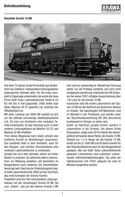
<strong>Betriebsanleitung</strong><br />
Diesellok Gravita <strong>10</strong> <strong>BB</strong><br />
Seit über 70 Jahren ist die Firma Voith aus Heidenheim<br />
als Zulieferer, insbesondere leistungsstarker<br />
hydraulischer Getriebe aktiv. Für die erste, komplett<br />
in Eigenregie entwickelte Lok wurde die neue<br />
Firma Voith Turbo Lokomotivtechnik GmbH & Co<br />
KG mit Sitz in Kiel gegründet. 2006 stellte man<br />
diese, Maxima 40 CC getaufte Lok, erstmals der<br />
Öffentlichkeit vor.<br />
Mit einer Leistung von 3600 kW handelt es sich<br />
um die stärkste einmotorige dieselhydraulische<br />
Lok. Da man von vornherein eine modulare Familie<br />
konstruierte, ist das Fahrzeug auch in einer<br />
anderen Leistungsklasse als Maxima 30 CC <strong>und</strong><br />
Maxima 20 <strong>BB</strong> erhältlich.<br />
Trotz dieses Wagnisses kam relativ schnell eine<br />
stattliche Anzahl an Bestellungen <strong>zu</strong>sammen.<br />
Das bestärkte Voith in dem Vorhaben, auch für<br />
den Rangier- <strong>und</strong> leichten Streckendienst eine<br />
modulare Lokomotivfamilie <strong>zu</strong> entwickeln.<br />
Gerade hier ist in den nächsten Jahren ein hoher<br />
Bedarf <strong>zu</strong> erwarten, da zahlreiche ältere Lokomotiven<br />
<strong>zu</strong>r Ablösung anstehen <strong>und</strong> besonders im<br />
Rangierdienst auch weiterhin die Dieseltraktion<br />
bevor<strong>zu</strong>gt wird. Nach kurzer Entwicklungszeit zeigte<br />
Voith Lokomotivtechnik 2008 auf der InnoTrans<br />
das erste Exemplar der Gravita-Familie.<br />
Projektiert sind hier fünf verschiedene Leistungsklassen<br />
von der vierachsigen Gravita 20 <strong>BB</strong>, bis<br />
<strong>zu</strong>m „Küken“, das auf den Namen Gravita 5 <strong>BB</strong><br />
1<br />
hört <strong>und</strong> nur zweiachsig ist. Obwohl das Fahrzeug<br />
bisher nur als Prototyp existierte <strong>und</strong> noch nicht<br />
weitgehend erprobt war, entschied sich DB Schenker<br />
bei seiner 2007 erfolgten Ausschreibung über<br />
130 Loks für die Gravita <strong>10</strong> <strong>BB</strong>.<br />
Inzwischen sind die ersten Lokomotiven der Gravita<br />
<strong>10</strong> <strong>BB</strong> bei der Northrail auf deutschen Gleisen<br />
im Einsatz. Die beauftragten DB-Maschinen sind<br />
im Moment in der Produktion <strong>und</strong> werden unter<br />
der Baureihenbezeichnung BR 260 demnächst<br />
b<strong>und</strong>esweit im Einsatz <strong>zu</strong> sehen sein.<br />
Außer an Northrail gingen bisher weitere 5<br />
Lokomotiven in die Schweiz. Um diesen Erfolg<br />
fort<strong>zu</strong>setzen, zeigte man 20<strong>10</strong> in Berlin die nächstgrößere<br />
Schwester dieser Reihe, die Gravita 15 <strong>BB</strong>.<br />
Obwohl nur 1,2 m länger als die Gravita <strong>10</strong> <strong>BB</strong>,<br />
leistet sie bis <strong>zu</strong> 1800 kW <strong>und</strong> ist damit sowohl für<br />
den Streckendienst als auch für den Rangierdienst<br />
geeignet. Alle von Voith Turbo Lokomotivtechnik<br />
gebauten Lokomotiven sind außerdem untereinander<br />
mehrfachtraktionstauglich. Die unter der<br />
Fabriknummer L04-15001 gebaute Lok wird im<br />
Moment eingehend erprobt.
Operating instructions<br />
Gravita <strong>10</strong> <strong>BB</strong><br />
For over 70 years, the Voith company of Heidenheim<br />
has been a supplier of vehicle parts, especially<br />
high-performance hydraulic transmissions.<br />
For the first engine developed completely in-house,<br />
the new company Voith Turbo Lokomotivtechnik<br />
GmbH & Co KG was fo<strong>und</strong>ed, with headquarters<br />
in Kiel. The first engine, christened the Maxima 40<br />
CC, had its public debut in 2006.<br />
With an output of 3600 kW, it is the strongest<br />
single-engine diesel- hydraulic locomotive. Since<br />
it was designed from the outset as a modular<br />
family, the vehicle is also available in a different<br />
performance class as the Maxima 30 CC and<br />
Maxima 20 <strong>BB</strong>.<br />
Despite the risk, a large number of orders were<br />
placed relatively quickly. This encouraged Voith in<br />
the project of developing a modular locomotive<br />
family for shunting and light line service.<br />
A high demand is expected in this area for the<br />
next few years, as many older locomotives<br />
are due for replacement and diesel traction is<br />
preferred, especially in shunting service. After a<br />
short development time, Voith Lokomotivtechnik<br />
presented the first sample of the Gravita family<br />
at InnoTrans 2008.<br />
Maßstabs- <strong>und</strong> originalgetreue Kleinmodelle<br />
für erwachsene Sammler.<br />
Zum Betrieb des vorliegenden Produkts<br />
darf als Spannungsquelle nur ein<br />
nach VDE 0551/EN 60742 gefertigter<br />
Spielzeug-Transformator verwendet<br />
werden.<br />
Elektro- <strong>und</strong> Elektronikaltgeräte dürfen<br />
nicht in den Hausmüll gelangen. Sie<br />
müssen entsprechend der jeweils<br />
gültigen Länderrichtlinien fachgerecht<br />
entsorgt werden.<br />
2<br />
Five different performance classes are projected,<br />
from the four-axle Gravita 20 <strong>BB</strong> to the „chicks“,<br />
which go by the name Gravita 5 <strong>BB</strong> and which have<br />
only two axles.Although the vehicle had only existed<br />
as a prototype andwas not yet widely tested, DB<br />
Schenker decided on morethan 130 locomotives<br />
for the Gravita <strong>10</strong> <strong>BB</strong> in its 2007 bid invitation.<br />
By now, the first units of the Gravita <strong>10</strong> <strong>BB</strong> are in<br />
use on the Northrail on German rail tracks. The designated<br />
DB machines are currently in production<br />
and will soon be seen in use nationwide <strong>und</strong>er the<br />
series designation BR 260.<br />
Apart from Northrail, another 5 locomotives went<br />
to Switzerland. Continuing this success, the next<br />
larger sister in this series, the Gravita 15 <strong>BB</strong>, was<br />
shown in Berlin in 20<strong>10</strong>. Although only 1.2 m<br />
longer than the Gravita <strong>10</strong> <strong>BB</strong>, it produces up to<br />
1,800kW, making it as suitable for line service as it<br />
is for shunting. All locomotives built by Voith Turbo<br />
Lokomotivtechnik are also suited for multi-led<br />
traction with each other. The engine assembled<br />
<strong>und</strong>er the serial number L04-15 001 is being<br />
exhaustively tested at present.<br />
Scale and true to original small-sized model<br />
for adult collectors.<br />
Only a toy transformer produced compliant<br />
with VDE 0551/EN 60742 may be used as a<br />
voltage source to operate this product.<br />
Electrical equipment may not reach to<br />
domestic waste. According to the current<br />
terms of the country reference the electrical<br />
eqipment must professional disposed.
Inhaltsverzeichnis<br />
Contents<br />
Benennung Seite<br />
• Allgemeine Hinweise .....................................3<br />
• Zusatzbauteile montieren ..............................4<br />
• Funktionstasten für So<strong>und</strong>-Modelle ...............4<br />
• Wartungsarbeiten<br />
1. Gehäuse demontieren ...............................5<br />
2. Platine abnehmen, Decoder einbauen ........5<br />
3. Motor tauschen,<br />
Antriebsschnecke ausbauen ......................5<br />
4. Drehgestell ausbauen, Räder wechseln<br />
<strong>und</strong> Zahnräder ausbauen ..........................5<br />
5. Haftreifen austauschen ..............................6<br />
6. Ölen ..........................................................6<br />
• Ersatzteile, Ersatzteilliste ......................8 – 11<br />
• Bestellbeispiel .............................................11<br />
Allgemeine Montage- <strong>und</strong><br />
Sicherheits hinweise<br />
• Diese Bedienungsanleitung beschreibt sämtliche<br />
Arbeitsvorgänge die <strong>zu</strong>r Wartung <strong>und</strong><br />
Instandhaltung notwendig sind. Bitte lesen Sie<br />
diese Bedienungsanleitung bevor Sie mit den<br />
Arbeiten beginnen.<br />
• Bei unsachgemäßem Umgang mit elektrischen<br />
Bauteilen können diese zerstört werden. Für<br />
entsprechende Arbeiten können Sie sich an<br />
Ihren Fachhändler oder den Hersteller wenden.<br />
• Bei den folgenden Wartungsarbeiten ist<br />
die jeweilige Demontage beschrieben, der<br />
Zusammenbau ist in umgekehrter Reihenfolge<br />
aus<strong>zu</strong>führen.<br />
• Achten Sie beim zerlegen der Lokomotive auf<br />
die Einbaulage der entsprechenden Bauteile.<br />
Wird ein Bauteil falsch eingebaut kann dieses<br />
zerstört werden oder es kommt <strong>zu</strong> Fuktionsstörungen<br />
im Betrieb.<br />
3<br />
Description Page<br />
• General information.......................................3<br />
• Fitting additional parts ...................................4<br />
• Function keys for so<strong>und</strong> models ....................4<br />
• Maintenance works<br />
1. Removing the housing ...............................5<br />
2. Removing the PCB, fitting decoder .............5<br />
3. Exchanging the motor, dismantling drive<br />
screw ........................................................5<br />
4. Removing the bogie, dismantling wheels<br />
and replacing gear wheels.........................5<br />
5. Replacing traction tyres .............................6<br />
6. Lubrication ................................................6<br />
• Spare parts list .....................................8 – 11<br />
• Order example ............................................11<br />
General assembly and safety information<br />
• These operating instructions describe all work<br />
steps necessary for maintenance and repair.<br />
Please read these operating instructions carefully<br />
before you start with your work.<br />
• In the case of incorrect handling of electrical<br />
components, they may be destroyed. Please<br />
ask your specialist dealer to help with the<br />
necessary work.<br />
• In the case of maintenance work, the disassembly<br />
is described below, to reassemble the<br />
tractor reverse the work steps.<br />
• When dismantling the engine make a note of<br />
the mounted position of the individual parts.<br />
An incorrectly mounted part can be destroyed<br />
or operation can be disrupted.
Zusatzbauteile<br />
Additional parts<br />
Zusatzbauteile montieren (Fig. 1)<br />
Werden die Zusatzbauteile für Vitrinenmodelle<br />
montiert, ist die Lok nicht mehr für den Fahrbetrieb<br />
geeignet.<br />
Pos. Bennenung Benötigte Anzahl<br />
40 Bremsleitung 8<br />
41 Hakenkupplung 2<br />
Fig. 1 / fig. 1<br />
Funktionstasten für So<strong>und</strong>-Modelle<br />
Die Lok-Varianten 62702, 62703, 62705, 62707,<br />
62709 <strong>und</strong> 62711 sind serienmäßig mit So<strong>und</strong><br />
ausgestattet.<br />
Die Belegung der Funktionstasten steht auf<br />
der <strong>BRAWA</strong> homepage www.brawa.de <strong>zu</strong>m<br />
Download bereit.<br />
4<br />
Fitting additional parts (fig. 1)<br />
If additional parts for showcase models are<br />
fitted, the locomotive is no longer suitable for<br />
running on tracks.<br />
Pos. Description Required number<br />
40 Brake tube 8<br />
41 Coupling hook 2<br />
Function keys for so<strong>und</strong> models<br />
The locos 62702, 67203, 62705, 62707 62709<br />
and 62711 have a so<strong>und</strong> decoder onboard.<br />
You can downlod the function key assignment at<br />
www.brawa.de.
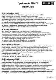
Wartungsarbeiten<br />
Maintenance works<br />
1. Gehäuse abnehmen (Fig. 3)<br />
Senkkopfschrauben (01) an der Unterseite des<br />
Chassis herausdrehen <strong>und</strong> Gehäuse (02) nach<br />
oben abnehmen.<br />
2. Platine abnehmen,<br />
Decoder einbauen (Fig. 3)<br />
Gehäuse demontieren, siehe Punkt 1.<br />
Die Cliphalterungen für die Platine (03) an den<br />
Motor-Halteklammern (05) lösen <strong>und</strong> Platine<br />
abnehmen. Decoder an der Schnittstelle (04)<br />
einstecken. Die Einsteckrichtung ist nach NEM<br />
651 mit der Ziffer 1 gekennzeichnet.<br />
3. Motor tauschen, Antriebsschnecken<br />
ausbauen (Fig. 3)<br />
Gehäuse demontieren, siehe Punkt 1.<br />
Platine abnehmen, siehe Punkt 2.<br />
– Motor tauschen<br />
Motor-Haltklammern (05) in Richtung<br />
Getriebeschnecke schieben <strong>und</strong> nach oben<br />
abziehen. Motor (06) aus Motorhalterung<br />
herausnehmen. Kabel am Motor ablöten.<br />
Beim ablöten auf Kabelstellung achten - sonst<br />
falsche Fahrtrichtung.<br />
4. Drehgestell ausbauen, Räder wechseln<br />
<strong>und</strong> Zahnräder tauschen (Fig. 3)<br />
Gehäuse demontieren, siehe Punkt 1.<br />
Platine abnehmen, siehe Punkt 2.<br />
Motor ausbauen, siehe Punkt 3.<br />
– Drehgestell ausbauen<br />
Drehgestellhalter (07) nach vorne bzw. hinten<br />
schieben <strong>und</strong> abnehmen. Lok-Chassis vorsichtig<br />
nach oben abnehmen.<br />
– Räder wechseln / Zahnräder tauschen<br />
Drehgestell (08) umdrehen <strong>und</strong> die Schnappverbindung<br />
am Drehgestellrahmen (09) <strong>und</strong><br />
Getriebegehäuse (<strong>10</strong>) lösen. Drehgestellrahmen<br />
abnehmen. Räder <strong>und</strong> Zahnräder aus<br />
Getriebegehäuse entnehmen <strong>und</strong> erneuern.<br />
5<br />
1. Removing the housing (fig. 3)<br />
Remove flat head screws (01) at the bottom and<br />
detach the chassis (02) upwards.<br />
2. Removing the PCB,<br />
Decoder installation (fig. 3)<br />
Demount chassis, (watch point 1).<br />
Detach the clip-fixation of the PCB (03) from the<br />
motor clips (05) and remove the PCB. Plug the<br />
decoder into interface (04). The plug in direction<br />
is marked after NEM 651 with number 1.<br />
2. Exchanging the motor, dismantling drive<br />
screw (fig. 3)<br />
Remove the housing, see item 1.<br />
Remove the PCB, see item 2.<br />
– Exchanging the motor<br />
Romove motor clip-fixation (05) in worm gear<br />
direction and pull upwards. Remove motor<br />
(06) from motor mounting. Unsolder the cable<br />
at the motor. Pay attention to the cable position<br />
when unsoldering, otherwise the travelling<br />
direction will be wrong.<br />
4. Removing the bogie, dismantling wheels<br />
and replacing gear wheels (fig. 3)<br />
Remove the housing, see item 1.<br />
Remove the PCB, see item 2.<br />
Exchanching the motor, see item 3.<br />
– Bogie uninstall<br />
Push/pull the bogie holder (07) and unfix it.<br />
Remove loco chassis carefully upwards.<br />
– Dismantling wheels and replacing gear<br />
wheels<br />
Turn bogie (08) upside down and remove the<br />
clip-fixation from the bogie frame (09) and<br />
the chassis (<strong>10</strong>). Remove the bogie frame.<br />
Remove wheels and gear wheels and replace<br />
them.
Wartungsarbeiten<br />
Maintenance works<br />
5. Haftreifen erneuern (Fig. 3)<br />
Zum Austausch der Haftreifen muss die Lok<br />
nicht komplett zerlegt werden.<br />
Lok umdrehen <strong>und</strong> die Schnappverbindung am<br />
Drehgestellrahmen (09) <strong>und</strong> Getriebegehäuse<br />
(<strong>10</strong>) lösen. Drehgestellrahmen abnehmen.<br />
Haftreifen abziehen <strong>und</strong> erneuern.<br />
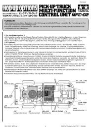
6. Ölen (Fig. 2<br />
Der Motor <strong>und</strong> die Lagerstellen der Radsätze<br />
können an den gekennzeichneten Punkten<br />
sparsam mit Öl der Modellbaubranche geölt<br />
werden. Zum Ölen des Motors sind das Gehäuse<br />
<strong>und</strong> die Platine ab<strong>zu</strong>nehmen, siehe Seite 5,<br />
Punkt 1 <strong>und</strong> 2.<br />
Fig. 2 / fig. 2<br />
Motor<br />
Motor<br />
Räder<br />
Wheels<br />
6<br />
5. Replacing traction tire (fig. 3)<br />
For a tracion tire replacement, the loco must not<br />
be disassambled totally.<br />
Turn loco upside down and remove the clipfixation<br />
from the bogie frame (09) and the<br />
chassis (<strong>10</strong>). Remove bogie frame. Remove and<br />
replace the tracion tires.<br />
6. Lubricating (fig. 2)<br />
The motor and the wheelset bearings may be<br />
sparingly lubricated at the marked places with<br />
oil used for model making purposes. In order to<br />
lubricate the motor, remove the housing and the<br />
PCB, compare page 5, item 1 and 2.
Wartungsarbeiten<br />
Maintenance works<br />
Fig. 3 / fig. 3<br />
7
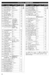
Ersatzteile<br />
Spare parts<br />
Ersatzteile Lokomotive Gravita <strong>10</strong> <strong>BB</strong><br />
Spare parts locomotive Gravita <strong>10</strong> <strong>BB</strong><br />
Gleichstrom / D.C. current<br />
8
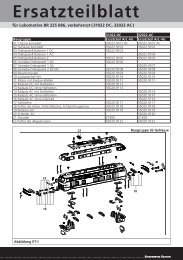
Ersatzteilliste<br />
Spare parts list<br />
Wichtiger Hinweis:<br />
Die Grafik gilt für mehrere Lok-Varianten, daher<br />
können mehr Einzelteile dargestellt sein als Sie<br />
an Ihrer Lok vorfinden.<br />
Bei der Montage einzelner Ersatzteile muss die<br />
Lok demontiert werden. Bitte achten Sie bei der<br />
Demontage darauf, dass kein Bauteil beschädigt<br />
wird, da nicht jedes Bauteil als Ersatzteil<br />
verfügbar ist.<br />
Die Lok-Varianten 62702, 62703, 62705, 62707,<br />
62709 <strong>und</strong> 62711 sind serienmäßig mit So<strong>und</strong><br />
ausgestattet. Platine <strong>und</strong> Lautsprecher <strong>zu</strong> diesen<br />
Varianten sind nicht als Ersatzteil verfügbar.<br />
9<br />
Important information:<br />
As this graphic chart is applicable to several loco<br />
designversions it is possible that more individual<br />
parts are represented than you will find on your<br />
loco.<br />
To fit individual spare parts it is necessary to<br />
dismantle the loco. Please be careful not to<br />
damage any components during removal as not<br />
every component is available as spare part.<br />
Loc so<strong>und</strong> is standard equiped to items 62702,<br />
62703, 62705, 62707, 62709 and 62711. For<br />
these models, PCB and speaker are not available<br />
as spare parts.<br />
62700<br />
62702<br />
Artikelnummer / Article number<br />
62701<br />
62703<br />
62704<br />
62705<br />
62706<br />
62707<br />
62708<br />
62709<br />
627<strong>10</strong><br />
62711<br />
Pos. Bennenung Description Bestell- Nr.<br />
Order-no.<br />
DC DC DC DC DC DC<br />
1 Radsatz kpl. Wheel complete 0015007.00 • • • • • •<br />
2 Radsatz mit Haftreifen kpl. Wheel with tration tire<br />
complete<br />
0015008.00 • • • • • •<br />
3 Motor kpl. Motor complete 0015014.00 • • • • • •<br />
4 Achse für Zahnrad Gear shaft 0015015.00 • • • • • •<br />
5 Zahnrad Gear wheel 0015016.00 • • • • • •<br />
6 Zahnrad Gear wheel 0015017.00 • • • • • •<br />
7 Zahnrad Gear wheel 0015019.00 • • • • • •<br />
8 Drehgestellhalter Bogie holder 0015020.00 • • • • • •<br />
9 Lüfter Gitter Grid 0015022.00 • • • • • •<br />
<strong>10</strong> Kamin Exhaust 0015026.00 • – – – – –<br />
0015026.01 – • – – – –<br />
0015026.02 – – • – – –<br />
0015026.03 – – – • – –<br />
0015026.04 – – – – • –<br />
0015026.05 – – – – – •<br />
11 Tank Tank 0015028.00 • – – – – –<br />
0015028.01 – • – – – –<br />
0015028.02 – – • – – –<br />
0015028.03 – – – • – –<br />
0015028.04 – – – – • –<br />
0015028.05 – – – – – •<br />
12 Tritt A Step A 0015032.00 • • • • • •<br />
13 Tritt B Step B 0015033.00 • • • • • •<br />
14 Handlauf kurz A Handrail short A 0015034.00 • – – – – –<br />
0015034.01 – – • – – –<br />
Handlauf kurz A 1 Handrail short A var 1 0015068.00 – • – – – –<br />
0015068.01 – – – – • –<br />
0015068.02 – – – – – •<br />
Handlauf kurz A 2 Handrail short A var 2 0015072.00 – – – • – –<br />
• = verfügbar / available<br />
– = nicht verfügbar / not available
Ersatzteile<br />
Spare parts<br />
<strong>10</strong><br />
62700<br />
62702<br />
Artikelnummer / Article number<br />
62701<br />
62703<br />
62704<br />
62705<br />
62706<br />
62707<br />
62708<br />
62709<br />
627<strong>10</strong><br />
62711<br />
Pos. Bennenung Description Bestell- Nr.<br />
Order-no.<br />
DC DC DC DC DC DC<br />
15 Handlauf kurz B Handrail short B 0015035.00 • – – – – –<br />
0015035.01 – – • – – –<br />
Handlauf kurz B 1 Handrail short B var 1 0015069.00 – • – – – –<br />
0015069.01 – – – – • –<br />
0015069.02 – – – – – •<br />
Handlauf kurz B 2 Handrail short B var 2 0015073.00 – – – • – –<br />
16 Handlauf lang A Handrail long A 0015036.00 • – – – – –<br />
0015036.01 – – • – – –<br />
Handlauf lang A 1 Handrail long A var 1 0015070.00 – • – – – –<br />
0015070.01 – – – – • –<br />
0015070.02 – – – – – •<br />
Handlauf lang A 2 Handrail long A var 2 0015074.00 – – – • – –<br />
17 Handlauf lang B Handrail long B 0015037.00 • – – – – –<br />
0015037.01 – – • – – –<br />
Handlauf lang B 1 Handrail long B var 1 0015071.00 – • – – – –<br />
0015071.01 – – – – • –<br />
0015071.02 – – – – – •<br />
Handlauf lang B 2 Handrail long B var 2 0015075.00 – – – • – –<br />
18 Motorhalter Motor bearing 0015040.00 • • • • • •<br />
19 Geländer vorn Handrail front 0015042.00 • – – – – –<br />
0015042.01 – • – – – –<br />
0015042.02 – – • – – –<br />
0015042.03 – – – • – –<br />
0015042.04 – – – – • –<br />
0015042.05 – – – – – •<br />
20 Lichtleiter Light bar 0015043.00 • • • • • •<br />
21 Senkschraube Countersink screw 0015045.00 • • • • • •<br />
22 Abdeckung Lichtleiter Light cover 0015046.00 • • • • • •<br />
23 Puffer Buffer 0015047.00 • • • • • •<br />
24 Kupplungsschacht Coupler pocket 0015048.00 • • • • • •<br />
25 Kupplungsfeder Coupler spring 0015049.00 • • • • • •<br />
26 Platine kpl. NEM 651* Main PCB cpl. NEM 651* 0015050.00 • • • • • •<br />
27 Lichtleiter Light bar 0015051.00 • • • • • •<br />
28 Lichtwand Light sheet 0015052.00 • • • • • •<br />
29 Rangiergriff Safety bow 0015053.00 • • • • • •<br />
30 Pufferhülse Bufferpart 0015054.00 • • • • • •<br />
31 Pufferhülse Bufferpart 0015054.01 • • • • • •<br />
32 Schienenräumer Track clearer 0015055.00 • • • • • •<br />
33 Motor Halteklammer Motor bearing 0015056.00 • • • • • •<br />
34 Sandbehälter Sandbox 0015057.00 • • • • • •<br />
35 Stützrahmen Support frame 0015058.00 • • • • • •<br />
36 Antenne Antenna 0015060.00 • • • • • •<br />
37 Antenne Antenna 0015061.00 • • • • • •<br />
38 Gebläse Leitung Pipe 0015062.00 • • • • • •<br />
39 Bremsleitungs Platte Brake tube board 0015063.00 • • • • • •<br />
* Platine <strong>und</strong> Lautsprecher für So<strong>und</strong>-Modelle nicht als Ersatzteil<br />
verfügbar.<br />
PCB and speaker for so<strong>und</strong> models are not avialable as spare<br />
parts.<br />
• = verfügbar / available<br />
– = nicht verfügbar / not available
Ersatzteile<br />
Spare parts<br />
11<br />
62700<br />
62702<br />
Artikelnummer / Article number<br />
62701<br />
62703<br />
62704<br />
62705<br />
62706<br />
62707<br />
62708<br />
62709<br />
627<strong>10</strong><br />
62711<br />
Pos. Bennenung Description Bestell- Nr.<br />
Order-no.<br />
DC DC DC DC DC DC<br />
40 Bremsleitung Brake tube 0015064.00 • • • • • •<br />
41 Hakenkupplung Coupling hook 0015065.00 • • • • • •<br />
42 Schlussscheibenhalter A Rear end disk holder A 0015066.00 • – – – – –<br />
0015066.01 – • – – – –<br />
0015066.02 – – • – – –<br />
0015066.03 – – – • – –<br />
0015066.04 – – – – • –<br />
0015066.05 – – – – – •<br />
43 Schlussscheibenhalter B Rear end disk holder B 0015067.00 • – – – – –<br />
0015067.01 – • – – – –<br />
0015067.02 – – • – – –<br />
0015067.03 – – – • – –<br />
0015067.04 – – – – • –<br />
0015067.05 – – – – – •<br />
44 Lampenghäuse kpl. Frontlight cpl. 00<strong>10</strong>038.00 • – – • – –<br />
00<strong>10</strong>038.01 – • – – – –<br />
00<strong>10</strong>038.02 – – • – – –<br />
00<strong>10</strong>038.03 – – – – • –<br />
00<strong>10</strong>038.04 – – – – – •<br />
45 Getriebegehäuse kpl. Gear box cpl. 00<strong>10</strong>039.00 • • • • • •<br />
46 Drehgestellrahmen kpl. Gear box cover cpl. 00<strong>10</strong>040.00 • • • • • •<br />
47 Blindstecker NEM 651 Blind plug NEM 651 00<strong>10</strong>042.00 • • • • • •<br />
48 Haftreifen Traction Tire 0015005.00 • • • • • •<br />
Bestellhinweis<br />
Bei der Bestellung von Ersatzteilen muss die<br />
Ersatzteil Bestell-Nr. <strong>und</strong> die Benennung angegeben<br />
werden. Ist dies nicht der Fall, kann die<br />
Bestellung nicht bearbeitet werden.<br />
Bestellbeispiel:<br />
Position (23), Puffer = 0015047.00, Puffer<br />
• = verfügbar / available<br />
– = nicht verfügbar / not available<br />
Order notice<br />
When ordering spare parts you must always<br />
state the order number and give the description.<br />
If you do not do this, the order cannot be<br />
processed.<br />
Order example:<br />
Position (23), Buffer = 0015047.00, Buffer
Brawa Artur Braun Modellspielwarenfabrik GmbH + Co.<br />
Uferstraße 26-28 · D-73630 Remshalden<br />
Hotline 07151 - 97 93 568<br />
Telefax 07151 - 7 46 62<br />
http://www.brawa.de<br />
62700.00.49 / 06 12 – WAN