Einstrang- Motorpumpen- Ölversorgung gruppen SMG Pumpen <strong>und</strong> Ventile <strong>Zubringer</strong>- <strong>und</strong> <strong>Druckaggregate</strong> Ölbrenner- Pumpenblöcke Pumpensteuerung Zubehör <strong>und</strong> Ersatzteile Monarch Ölbrennerdüsen Allgemeines Sonderaggregate 6 6 hpTECHNIK www.hptechnik.com www.hptechnik.com Industriepumpen Baureihe B ohne Überstromventil Überströmventil 1.1 Technische Auswahltabelle; Maßbilder Maßbilder Die Die Drehrichtung der Pumpe I = indirekt = – indirekt linksdrehend – linksdrehend D = direkt = – direkt rechtsdrehend – rechtsdrehend Die Drehrichtung kann nur im im Werk geändert werden. werden. Deshalb gewünschte Drehrichtung mit Blick auf Pumpenwelle gemäß Maßblatt Maßblatt bei Bestellung angeben! Industriepumpen hp-Innen- Viskosität: 6 mm2 sec -1 bei 20°C zahnradpumpe n = 1400 min Gewinde- Manometer- max. zul. Netto- anschluß * anschluß Pumpen- gewicht -1 n = 2800 min -1 Baureihe Förderstrom l/h Förderstrom l/h Rohr- Rohr- drehzahl (kg) gewinde gewinde (min -1 hp-Innenzahnradpumpen bis 40 bar (Drehrichtung I = indirekt – linksdrehend) Viskosität: 6 mm² sec hp-Innenzahnradpumpe Baureihe B B Größen: bei bei bei Artikel Nr. bei bei bei Artikel Nr. Größen: 9 bar 30 bar 40 bar I 9 bar 30 bar 40 bar I BP 45 30 20 011/0002 90 60 50 013/0002 BM 80 60 50 011/0003 160 130 120 013/0003 BG 120 100 80 011/0004 240 200 190 013/0004 BF 160 140 120 011/0005 320 270 260 013/0005 ) Trieb Wellen DIN DIN Ø Ø ISO 228 ISO 228 bei I/D bei I/D 25 12 3/8“ – 2800 1,8 25 12 3/8“ – 2800 1,8 25 12 3/8“ – 2800 1,8 25 12 3/8“ – 2800 1,8 BG PP 150 BG PZ 200 BG P 300 BG MZ – BG M 450 BG GZ – BG G 600 100 160 240 – 390 – 540 80 140 200 – 360 – 480 011/0052 300 011/0053 400 011/0019 600 – 850 011/0020 900 – 1100 011/0021 – 240 310 520 750 850 1000 – 210 280 480 700 730 870 – 013/0052 013/0053 013/0019 013/0068 013/0020 013/0054 – 38 38 38 38 38 38 38 12 12 12 12 12 12 12 1/2“ 1/2“ 1/2“ 1/2“ 1/2“ 1/2“ 1/2“ – – – – – – – 2800 2800 2800 2800 2800 2800 1680 2,6 2,6 2,6 2,6 2,6 2,6 2,6 BH P BH M BH G 1000 1500 2000 700 600 1200 1000 1700 1400 011/0031 – 011/0032 – 011/0033 – – – – – – – – – – 56 56 56 18 18 18 3/4“ 3/4“ 3/4“ 1/4“ 1/4“ 1/4“ 1680 1680 1680 6,4 6,4 6,4 -1 bei 20°C GewindeManometer- max. zul. Pumanschluss*anschlusspendrehzahl Rohrgewinde Rohrgewinde (min DIN ISO 228 DIN ISO 228 -1 n = 1400 min Nettogewicht (kg) ) bei l/D bei l/D -1 Förderstrom l/h n = 2800 min -1 hp-Innenzahnradpumpen bis 40 bar (Drehrichtung I = indirekt – linksdrehend) Förderstrom l/h bei bei bei Artikel-Nr bei bei bei Artikel-Nr 9 bar 30 bar 40 bar l 9 bar 30 bar 40 bar l BP 45 30 20 011/0002 90 60 50 013/0002 BM 80 60 50 011/0003 160 130 120 013/0003 BG 120 100 80 011/0004 240 200 190 013/0004 BF 160 140 120 011/0005 320 270 260 013/0005 Trieb Wellen Ø Ø 25 12 3/8“ – 3500 1,8 25 12 3/8“ – 3500 1,8 25 12 3/8“ – 3500 1,8 25 12 3/8“ – 3500 1,8 BG PP BG PZ BG P BG MZ BG M BG GZ BG G 150 200 300 – 450 – 600 100 160 240 – 390 – 540 80 011/0052 140 011/0053 200 011/0019 – – 360 011/0020 – – 480 011/0021 300 240 400 310 600 520 850 750 900 850 1100 1000 1200 1080 210 280 480 700 730 870 960 013/0052 013/0053 013/0019 013/0068 013/0020 013/0054 013/0031 38 38 38 38 38 38 38 12 12 12 12 12 12 12 1/2“ 1/2“ 1/2“ 1/2“ 1/2“ 1/2“ 1/2“ – – – – – – – 3500 3500 3500 3500 3500 3500 2800 2,6 2,6 2,6 2,6 2,6 2,6 2,6 BH P BH M BH G 1000 700 1500 1200 2000 1700 600 011/0031 1000 011/0032 1400 011/0033 – – – – – – – – – – – – 56 56 56 18 18 18 3/4“ 3/4“ 3/4“ 1/4“ 1/4“ 1/4“ 1700 1700 1700 6,4 6,4 6,4 BHG P 3000 BHG PZ 3700 BHG M 4500 BHG G 6000 2200 2000 3000 2700 3600 3200 4800 – 011/0043 – 011/0080 – 011/0044 – 011/0045 – – – – – – – – – – – – – 75 75 75 75 22 22 22 22 1 1/2“ 1 1/2“ 1 1/2“ 1 1/2“ – – – – 1400 1400 1400 1400 14,9 14,9 14,9 14,9 Pumpe Viskosität: 6 mm2 sec -1 bei 20°C Baureihe n = 1400 min Gewinde- Manometer- Heizleistung Losbrech- -1 n = 2800 min -1 BHG P BHG PZ BHG M BHG G 3000 2200 3700 3000 4500 3600 6000 4800 2000 011/0043 2700 011/0080 3200 011/0044 – 011/0045 – – – – – – – – – – – – – – – – 75 75 75 75 22 22 22 22 1 1/2“ 1 1/2“ 1 1/2“ 1 1/2“ – – – – 1700 1700 1700 1700 14,9 14,9 14,9 14,9 hp-Innenzahnradpumpen bis 40 bar (Drehrichtung D = direkt – rechtsdrehend) Viskosität: 6 mm² sec hp-Innenzahnradpumpe Baureihe B B Förderstrom l/h Förderstrom l/h Größen: bei bei bei Artikel Nr. bei bei bei Artikel Nr. Trieb anschluß * anschluß H1 in Watt moment 230 V, der Pumpe Wellen 50 Hz (Nm) Größen: 9 bar 30 bar 40 bar D 9 bar 30 bar 40 bar D Ø Ø BP BM BG 45 80 120 30 60 100 20 50 80 012/0002 90 012/0003 160 012/0004 240 60 130 200 50 120 190 014/0002 014/0003 014/0004 25 25 25 12 12 12 3/8“ 3/8“ 3/8“ – – – 100 100 100 1,2 1,2 1,2 BF 160 140 120 012/0005 320 270 260 014/0005 25 12 3/8“ – 100 1,2 BG PP 150 100 80 012/0052 300 240 210 014/0052 38 12 1/2“ – 100 1,6 BG PZ 200 160 140 012/0053 400 310 280 014/0053 38 12 1/2“ – 100 1,6 BG P 300 240 200 012/0019 600 520 480 014/0019 38 12 1/2“ – 100 1,6 BG-MZ – – – – 850 750 700 014/0068 38 12 1/2“ – 100 1,6 BG M 450 390 360 012/0020 900 800 730 014/0020 38 12 1/2“ – 100 1,6 BG GZ – – – – 1100 930 870 014/0054 38 12 1/2“ – 100 1,6 BG G 600 540 480 012/0021 – – – – 38 12 1/2“ – 100 1,6 BH P 1000 700 600 012/0031 – – – – 56 18 3/4“ 1/4“ 160 3,2 BH M 1500 1200 1000 012/0032 – – – – 56 18 3/4“ 1/4“ 160 3,2 BH G 2000 1700 1400 012/0033 – – – – 56 18 3/4“ 1/4“ 160 3,2 BHG P 3000 2200 2000 012/0043 – – – – 75 22 1 1/2“ – 280 4,6 BHG PZ 3700 3000 2700 012/0080 – – – – 75 22 1 1/2“ – 280 4, BHG M 4500 3600 3200 012/0044 – – – – 75 22 1 1/2“ – 280 4,6 BHG G 6000 4800 – 012/0045 – – – – 75 22 1 1/2“ – 280 4,6 -1 bei 20°C n = 1400 min GewindeManometerLosbrechanschluss*anschluss Heizleistung moment der Rohrgewinde Rohrgewinde H1 in Watt Pumpe DIN ISO 228 DIN ISO 228 230 V, 50 Hz (Nm) -1 Förderstrom l/h n = 2800 min -1 hp-Innenzahnradpumpen bis 40 bar (Drehrichtung D = direkt – rechtsdrehend) Förderstrom l/h bei bei bei Artikel-Nr bei bei bei Artikel-Nr 9 bar 30 bar 40 bar D 9 bar 30 bar 40 bar D Trieb Wellen Ø Ø BP 45 30 20 012/0002 90 60 50 014/0002 25 12 3/8“ – 100 1,2 BM BG BF 80 120 160 60 100 140 50 012/0003 80 012/0004 120 012/0005 160 130 240 200 320 270 120 190 260 014/0003 014/0004 014/0005 25 25 25 12 12 12 3/8“ 3/8“ 3/8“ – – – 100 100 100 1,2 1,2 1,2 BG PP 150 100 80 012/0052 300 240 210 014/0052 38 12 1/2“ – 100 1,6 BG PZ 200 160 140 012/0053 400 310 280 014/0053 38 12 1/2“ – 100 1,6 BG P 300 240 200 012/0019 600 520 480 014/0019 38 12 1/2“ – 100 1,6 BG-MZ – – – – 850 750 700 014/0068 38 12 1/2“ – 100 1,6 BG M 450 390 360 012/0020 900 850 730 014/0020 38 12 1/2“ – 100 1,6 BG GZ – – – – 1100 1000 870 014/0054 38 12 1/2“ – 100 1,6 BG G 600 540 480 012/0021 1200 1080 960 014/0031 38 12 1/2“ – 100 1,6 BH P 1000 700 600 012/0031 – – – – 56 18 3/4“ 1/4“ 160 3,2 BH M 1500 1200 1000 012/0032 – – – – 56 18 3/4“ 1/4“ 160 3,2 BH G 2000 1700 1400 012/0033 – – – – 56 18 3/4“ 1/4“ 160 3,2 BHG P 3000 2200 2000 012/0043 – – – – 75 22 1 1/2“ – 280 4,6 BHG PZ 3700 3000 2700 012/0080 – – – – 75 22 1 1/2“ – 280 4 BHG M 4500 3600 3200 012/0044 – – – – 75 22 1 1/2“ – 280 4,6 BHG G 6000 4800 – 012/0045 – – – – 75 22 1 1/2“ – 280 4,6 * Für eine einwandfreie Pumpenfunktion müssen die Rohrleitungen nach den strömungstechnischen Gr<strong>und</strong>lagen durch Strangrechnung entsprechend den örtlichen Verhältnissen dimensioniert * Für eine einwandfreie Pumpenfunktion müssen die Rohrleitungen nach den strömungstechnischen Gr<strong>und</strong>lagen durch Strangrechnung entsprechend den örtlichen Verhältnissen dimensioniert werden! Der Pumpen- oder <strong>Geräte</strong>anschluss gibt keinen Hinweis auf die entsprechende Rohrleitungsdimension. werden! Der Pumpen- oder <strong>Geräte</strong>anschluß gibt keinen Hinweis auf die entsprechende Rohrleitungsdimension. Baureihe B
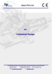
Triebgröße Ø 1400 min -1 Förderstrom l/h 2800 min -1 Leitungsanschlüsse zyl. Withworth-Rohrgewinde G...A DIN ISO 228 Sauganschluss Druckanschluss D = Rechtslauf I = Linkslauf a1 a2 a3 b1 c1 c2 c3 c4 c5 c6 c7 c8 d1 25 45 - 160 90 - 320 35,5 20 33 51 41,5 14 16 40 20 55,5 76 131,5 12 38 150 - 600 300 - 1200 43 26,5 38 70 55,5 14 16 40 20 69,5 76 145,5 12 56 1000 - 2000 – 48,5 38 45 96 71,5 15 18 79 27 86,5 124 210,5 18 75 3000 - 6000 – 64,5 83 70 115 129,5 18 25 65 37 147,5 127 274,5 22 Triebgröße Ø 1400 min -1 www.hptechnik.com Maßbilder für Baureihe B 1.1 Förderstrom l/h 2800 min -1 sw e d2 d3 e1 e2 f2 f3 f4 g1 h1 h2 h3 25 45 - 160 90 - 320 27 31,2 54 80 G 3/8“ 71 16,5 38 92 43 11 13 13 38 150 - 600 300 - 1200 27 31,2 54 80 G 1/2“ 82 19 44 92 43 11 13 13 56 1000 - 2000 – 46 53,1 60 100 G 3/4“ 112 22,5 67 120 65 13 13 25 75 3000 - 6000 – 55 63,5 80 120 G 1 1/2“ 170 35 100 150 90 14,5 15 – Bei Triebgröße 56 Vakuum- <strong>und</strong> Manometeranschluss G 1/4“ auf der Stirnseite. Industriepumpen Pumpen <strong>und</strong> Ventile Motorpumpengruppen SMG Einstrang- Ölversorgung <strong>Zubringer</strong>- <strong>und</strong> <strong>Druckaggregate</strong> Ölbrenner- Pumpenblöcke Pumpensteuerung Zubehör <strong>und</strong> Ersatzteile Monarch Ölbrennerdüsen Allgemeines Sonderaggregate 7


![2012 hpTECHNIK Catalog (pdf) [click here]](https://img.yumpu.com/2835588/1/184x260/2012-hptechnik-catalog-pdf-click-here.jpg?quality=85)