Planetengetriebe Planetary gearboxes - Vogel Antriebstechnik
Planetengetriebe Planetary gearboxes - Vogel Antriebstechnik
Planetengetriebe Planetary gearboxes - Vogel Antriebstechnik

Sie wollen auch ein ePaper? Erhöhen Sie die Reichweite Ihrer Titel.
YUMPU macht aus Druck-PDFs automatisch weboptimierte ePaper, die Google liebt.
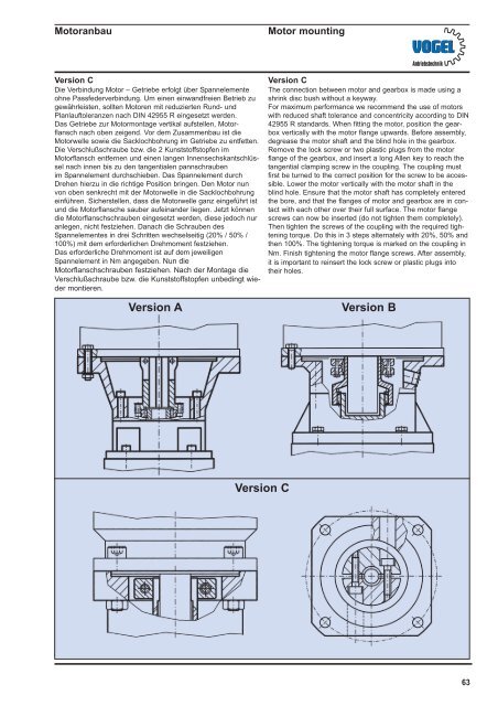
Motoranbau<br />
Motor mounting<br />
<strong>Antriebstechnik</strong><br />
Version C<br />
Die Verbindung Motor – Getriebe erfolgt über Spannelemente<br />
ohne Passfederverbindung. Um einen einwandfreien Betrieb zu<br />
gewährleisten, sollten Motoren mit reduzierten Rund- und<br />
Planlauftoleranzen nach DIN 42955 R eingesetzt werden.<br />
Das Getriebe zur Motormontage vertikal aufstellen, Motorflansch<br />
nach oben zeigend. Vor dem Zusammenbau ist die<br />
Motorwelle sowie die Sacklochbohrung im Getriebe zu entfetten.<br />
Die Verschlußschraube bzw. die 2 Kunststoffstopfen im<br />
Motorflansch entfernen und einen langen Innensechskantschlüssel<br />
nach innen bis zu den tangentialen pannschrauben<br />
im Spannelement durchschieben. Das Spannelement durch<br />
Drehen hierzu in die richtige Position bringen. Den Motor nun<br />
von oben senkrecht mit der Motorwelle in die Sacklochbohrung<br />
einführen. Sicherstellen, dass die Motorwelle ganz eingeführt ist<br />
und die Motorflansche sauber aufeinander liegen. Jetzt können<br />
die Motorflanschschrauben eingesetzt werden, diese jedoch nur<br />
anlegen, nicht festziehen. Danach die Schrauben des<br />
Spannelementes in drei Schritten wechselseitig (20% / 50% /<br />
100%) mit dem erforderlichen Drehmoment festziehen.<br />
Das erforderliche Drehmoment ist auf dem jeweiligen<br />
Spannelement in Nm angegeben. Nun die<br />
Motorflanschschrauben festziehen. Nach der Montage die<br />
Verschlußschraube bzw. die Kunststoffstopfen unbedingt wieder<br />
montieren.<br />
Version A<br />
Version C<br />
The connection between motor and gearbox is made using a<br />
shrink disc bush without a keyway.<br />
For maximum performance we recommend the use of motors<br />
with reduced shaft tolerance and concentricity according to DIN<br />
42955 R standards. When fitting the motor, position the gearbox<br />
vertically with the motor flange upwards. Before assembly,<br />
degrease the motor shaft and the blind hole in the gearbox.<br />
Remove the lock screw or two plastic plugs from the motor<br />
flange of the gearbox, and insert a long Allen key to reach the<br />
tangential clamping screw in the coupling. The coupling must<br />
first be turned to the correct position for the screw to be accessible.<br />
Lower the motor vertically with the motor shaft in the<br />
blind hole. Ensure that the motor shaft has completely entered<br />
the bore, and that the flanges of motor and gearbox are in contact<br />
with each other over their full surface. The motor flange<br />
screws can now be inserted (do not tighten them completely).<br />
Then tighten the screws of the coupling with the required tightening<br />
torque. Do this in 3 steps alternately with 20%, 50% and<br />
then 100%. The tightening torque is marked on the coupling in<br />
Nm. Finish tightening the motor flange screws. After assembly,<br />
it is important to reinsert the lock screw or plastic plugs into<br />
their holes.<br />
Version B<br />
Version C<br />
63