PUMPENGRUPPEN Technische Information für Montage und - Cosmo
PUMPENGRUPPEN Technische Information für Montage und - Cosmo
PUMPENGRUPPEN Technische Information für Montage und - Cosmo

Erfolgreiche ePaper selbst erstellen
Machen Sie aus Ihren PDF Publikationen ein blätterbares Flipbook mit unserer einzigartigen Google optimierten e-Paper Software.
P U M P E N G R U P P E N<br />
<strong>Technische</strong> <strong>Information</strong><br />
<strong>für</strong> <strong>Montage</strong> <strong>und</strong> Betrieb<br />
P U M P G R O U P S<br />
Technical information<br />
for installation and operation
INHALT<br />
SICHERHEITSHINWEISE<br />
Seite<br />
1 Pumpengruppen UK<br />
(ungemischter Kreis) 3<br />
Pumpengruppen MK<br />
(gemischter Kreis) 3<br />
3 Pumpengruppen UKZ<br />
(ungemischter Kreis) 4<br />
4 Pumpengruppen MKZ<br />
(gemischter Kreis) 4<br />
5 Wandmontage 5<br />
6 Einsatz von Hoch-<br />
effizienzpumpen 6<br />
7 Einbau Überströmset 6<br />
8 Mischer 7<br />
9 Thermometerwechsel 8<br />
10 Schwerkraftbremse 8<br />
11 Service-Hinweise zur<br />
sach- <strong>und</strong> funktionsgerechten<br />
Inbetriebnahme der Heizanlage 8<br />
1 Trennsysteme (<strong>für</strong> Anschluss<br />
am geregelten Heizkreis)<br />
12.1 Service - <strong>und</strong> Sicherheitshinweise 9<br />
13 Konstantwertregelset<br />
13.1 Konstantwertregelset<br />
(thermostatisch geregelt) 10<br />
13.1.1 Einsatzbeispiel 11<br />
13.1.2 Einstellen der Temperatur des<br />
geregelten Heizkreises 11<br />
13.1.3 Sicherheitstemperatur-<br />
begrenzung (Anlegethermostat) 11<br />
14 Rücklaufanhebung<br />
14.1 Rücklaufanhebung DN 25 (1”)<br />
(thermostatisch geregelt) 1<br />
14.1.1 Einsatzbeispiel 13<br />
14.1.2 Einstellen der Rücklauftemperatur 13<br />
14.2 Rücklaufanhebung MK DN 25 (1”)<br />
(elektronisch geregelt) 13<br />
Sicherheitshinweise<br />
Bitte befolgen Sie diese Sicherheitshinweise<br />
genau, um Gefahren <strong>und</strong> Schäden <strong>für</strong> Menschen <strong>und</strong><br />
Sachwerte auszuschließen.<br />
Die <strong>Montage</strong>, Erstinbetriebnahme, Inspektion, Wartung<br />
<strong>und</strong> Instandsetzung müssen von einer zugelassenen<br />
Fachfirma ausgeführt werden. Machen Sie sich vor<br />
Arbeitsbeginn mit allen Teilen <strong>und</strong> deren Handhabung<br />
vertraut.<br />
Beachten Sie die gültigen Unfallverhütungsvorschriften,<br />
Umweltvorschriften <strong>und</strong> gesetzlichen Regeln <strong>für</strong> die<br />
<strong>Montage</strong>, Installation <strong>und</strong> den Betrieb. Des weiteren<br />
die relevanten einschlägigen Richtlinien der DIN, EN,<br />
DVGW, VDI <strong>und</strong> VDE sowie alle aktuellen relevanten<br />
länderspezifischen Normen, Gesetze <strong>und</strong> Richtlinien.<br />
Arbeiten an der Anlage:<br />
Anlage spannungsfrei schalten <strong>und</strong> auf Spannungsfreiheit<br />
kontrollieren (z. B. an der separaten<br />
Sicherung oder einem Hauptschalter). Anlage gegen<br />
Wiedereinschalten sichern. (Bei Brennstoff Gas den<br />
Gasabsperrhahn schließen <strong>und</strong> gegen unbeabsichtigtes<br />
Öffnen sichern). Instandsetzungsarbeiten an<br />
Bauteilen mit sicherheitstechnischer Funktion sind<br />
unzulässig.<br />
Die in der nachfolgenden Anleitung benannten<br />
Bauteile sind <strong>für</strong> den Einsatz in Heizungsanalagen<br />
nach DIN EN 12828 bestimmt.<br />
Vor Gebrauch <strong>Montage</strong>anleitung<br />
lesen<br />
Schnittgefahr<br />
Quetschgefahr<br />
Gefahr erhöhter Temperatur<br />
Gefahr elektrischer Spannung<br />
Sturzgefahr bei der <strong>Montage</strong>
1 Pumpengruppen UK (ungemischter Kreis)<br />
Druckverlust (bar)<br />
<strong>Technische</strong> Daten:<br />
DN: 25 | 32<br />
oberer Anschluss: 1“ IG | 1 1/4“ IG<br />
unterer Anschluss: G 1 1/2“ AG<br />
(flachdichtend)<br />
Achsabstand: 125 mm<br />
Bauteile aus: Stahl, Messing,<br />
EPP-Isolierung<br />
Abmessung: ca.<br />
H 420 x B 250 x T 255 mm<br />
Dichtmaterialien: PTFE, asbestfreie Faserdichtung,<br />
EPDM<br />
Temperaturanzeige: 0 bis 120 °C<br />
Einsatztemperatur: bis 110 °C<br />
Betriebsdruck: PN 6<br />
kVs – Wert: 9,7 | 11<br />
GC-KBN: CPGU | CPGU32<br />
Volumenstrom-Druckverlust-Diagramm<br />
Pumpengruppen UK<br />
Volumenstrom (l/h)<br />
3<br />
1 <strong>PUMPENGRUPPEN</strong> UK<br />
2 <strong>PUMPENGRUPPEN</strong> MK<br />
2 Pumpengruppen MK (gemischter Kreis)<br />
Druckverlust (bar)<br />
<strong>Technische</strong> Daten:<br />
DN: 25 | 32<br />
oberer Anschluss: 1“ IG | 1 1/4“ IG<br />
unterer Anschluss: G 1 1/2“ AG<br />
(flachdichtend)<br />
Achsabstand: 125 mm<br />
Bauteile aus: Stahl, Messing,<br />
EPP-Isolierung<br />
Abmessung: ca.<br />
H 420 x B 250 x T 255 mm<br />
Dichtmaterialien: PTFE, asbestfreie Faserdichtung,<br />
EPDM<br />
Temperaturanzeige: 0 bis 120 °C<br />
Einsatztemperatur: bis 110 °C<br />
Betriebsdruck: PN 6<br />
kVs – Wert: 6,2 | 6,4<br />
GC-KBN: CPGM | CPGM32<br />
Volumenstrom-Druckverlust-Diagramm<br />
Pumpengruppen MK mit 3-Wege - T - Mischer<br />
Volumenstrom (l/h)
4<br />
3 <strong>PUMPENGRUPPEN</strong> UKZ<br />
4 <strong>PUMPENGRUPPEN</strong> MKZ<br />
3 Pumpengruppen UKZ (ungemischter Kreis)<br />
Mit Zählereinbaustrecke einschließlich Teleskopstück<br />
<strong>und</strong> Fühlermuffe 1/2“ IG.<br />
Passmaß <strong>für</strong> Zähler:<br />
3/4“ AG x 110 mm<br />
1“ AG x 130 mm<br />
<strong>Technische</strong> Daten:<br />
DN: 25<br />
oberer Anschluss: G 1“ IG<br />
unterer Anschluss: G 1 1/2“ AG<br />
(flachdichtend)<br />
Achsabstand: 125 mm<br />
Bauteile aus: Stahl, Messing,<br />
EPP-Isolierung<br />
Abmessung: ca.<br />
H 420 x B 250 x T 255 mm<br />
Dichtmaterialien: PTFE, asbestfreie Faserdichtung,<br />
EPDM<br />
Temperaturanzeige: 0 bis 120 °C<br />
Einsatztemperatur: bis 110 °C<br />
Betriebsdruck: PN 6<br />
kVs – Wert: 9,7<br />
GC-KBN: CPGUZ<br />
4 Pumpengruppen MKZ (gemischter Kreis)<br />
Mit Zählereinbaustrecke einschließlich Teleskopstück<br />
<strong>und</strong> Fühlermuffe 1/2“ IG.<br />
Passmaß <strong>für</strong> Zähler:<br />
3/4“ AG x 110 mm<br />
1“ AG x 130 mm<br />
<strong>Technische</strong> Daten:<br />
DN: 25<br />
oberer Anschluss: G 1“ IG<br />
unterer Anschluss: G 1 1/2“ AG<br />
(flachdichtend)<br />
Achsabstand: 125 mm<br />
Bauteile aus: Stahl, Messing,<br />
EPP-Isolierung<br />
Abmessung: ca.<br />
H 420 x B 250 x T 255 mm<br />
Dichtmaterialien: PTFE, asbestfreie Faserdichtung,<br />
EPDM<br />
Temperaturanzeige: 0 bis 120 °C<br />
Einsatztemperatur: bis 110 °C<br />
Betriebsdruck: PN 6<br />
kVs – Wert: 6,2<br />
GC-KBN: CPGMZ
1. Pumpengruppe mit Isolierung an vohandene<br />
Verrohrung anbringen.<br />
. Befestigung handfest anziehen.<br />
3. Untere Seiten <strong>und</strong> Mitte anzeichnen <strong>und</strong><br />
anschließend Pumpengruppe mit ISO wieder<br />
entfernen.<br />
4. Wand nach Markierung bohren <strong>und</strong> Dübel<br />
einsetzen.<br />
5. Unterschale der Isolierung mit mitgelieferten<br />
Schrauben an der Wand befestigen.<br />
5<br />
5 WANDMONTAGE
6<br />
6 EINSATZ VON HOCHEFFIZIENZPUMPEN<br />
7 EINBAU ÜBERSTRÖMSET<br />
6 Einsatz von Hocheffizienzpumpen<br />
Die Pumpengruppen sind <strong>für</strong> den Einsatz von Hocheffizienzpumpen<br />
geeignet. Für den Einsatz von<br />
Hocheffizienzpumpen gelten die vom Pumpenhersteller<br />
geforderten <strong>Montage</strong>- <strong>und</strong> Betriebsrichtlinien.<br />
Fabrikat GRUNDFOS.<br />
Typ: Alpha 2<br />
Max.Vorlauf- / 80 °C<br />
Medientemperatur<br />
Max. Umgebungs- / 27 °C<br />
Raumtemperatur<br />
Besonderheiten: Pumpenstecker in<br />
Winkelform verwenden<br />
Fabrikat WILO<br />
Typ: Stratos Eco<br />
Max.Vorlauf- / 85 °C<br />
Medientemperatur<br />
Max. Umgebungs- / 30 °C<br />
Raumtemperatur<br />
Beim Einsatz von Hocheffizienzpumpen ist der<br />
Isolationsstopfen zu entfernen.<br />
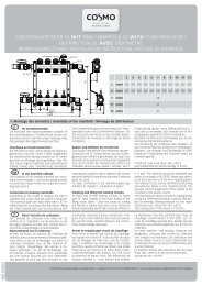
7 Einbau Überströmset<br />
Der zwischen den Kugelhähnen (1) flachdichtend eingebaute<br />
Stabilisator (2) lässt sich im Bedarfsfall gegen<br />
ein Überströmset (3) tauschen, ohne den Heizkreis<br />
abzulassen.<br />
Einbau:<br />
1. Isolierung entfernen.<br />
2. Pumpe abschalten <strong>und</strong> alle Kugelhähne schließen.<br />
3. Überwurfmuttern des Stabilisators lösen <strong>und</strong><br />
Stabilisator nach vorn ziehen. Achtung: leichter<br />
Wasseraustritt möglich.<br />
4. Überströmset einsetzen <strong>und</strong> Überwurfmuttern<br />
anziehen. Achtung: Durchströmrichtung (Pfeil auf<br />
Gehäuse) von der Vorlauf- zur Rücklaufseite beachten.<br />
5. Kugelhähne wieder öffnen <strong>und</strong> die Pumpe anschalten.<br />
6. Ventil auf gewünschten Regelbereich einstellen.<br />
7. Isolierung anbringen.
8 Mischer<br />
Die Lage des Bypasses geht aus der Abbildung hervor.<br />
Am Bypass lässt sich die Vorlauf-Temperatur<br />
durch Beimengung von Rücklaufwasser absenken.<br />
Die Einstellung des Bypasses ist stufenlos möglich.<br />
Dazu muss die Sicherheitsschraube (1) ca. 1 mm<br />
gelöst werden. Bei geöffnetem Bypass steht der<br />
Schlitz der Einstellschraube (2) parallel zur Kante des<br />
Bypasskanals.<br />
Bei geschlossenem Bypass steht der Schlitz im rechten<br />
Winkel zur Kante des Bypasskanals.<br />
Funktionsprinzip 3-Wege-Mischer<br />
Mischer „offen“<br />
voller Zulauf kesselseitig<br />
keine Beimischung rücklaufseitig<br />
RP<br />
FP<br />
Bypass-Einstellung<br />
Kante Bypasskanal<br />
Bypass in Stellung ZU<br />
Mischer „geschlossen“<br />
voller Zulauf rücklaufseitig<br />
kein Zulauf kesselseitig<br />
Bypass<br />
(in Stellung geschlossen)<br />
Klemmschraube<br />
<strong>für</strong> Bypass<br />
Abflachung am<br />
Wellenende in<br />
dieser Position<br />
2<br />
1<br />
Vorlauf rechts<br />
Kante Bypasskanal<br />
Bypass in Stellung AUF<br />
Zugehörige<br />
Griffstellung<br />
Schließelement<br />
7<br />
8 MISCHER
8<br />
9 THERMOMETERWECHSEL<br />
10 SCHWERKRAFTBREMSE<br />
11 SERVICE HINWEISE<br />
9 Thermometerwechsel<br />
Die Thermometer sind nur eingesteckt <strong>und</strong> lassen<br />
sich einfach durch Herausziehen tauschen.<br />
Es sollte beachtet werden, dass ein entnommenes<br />
Thermometer durch ein gleichartiges ersetzt wird.<br />
Bitte auf die farbliche Kennzeichnung achten.<br />
(rote Schrift = VL; blaue Schrift = RL)<br />
11 Service-Hinweise zur sach- <strong>und</strong> funk tionsgerechten<br />
Inbetriebnahme der Heizanlage<br />
Achtung!<br />
Nach dem Befüllen <strong>und</strong> der an schließenden<br />
Druck- <strong>und</strong> Dichtheits prüfung des Kessels<br />
bzw. Speichers darf die Verbindung zum nachfolgenden<br />
Rohrsystem nur durch die Betätigung<br />
(Öffnen) des Dreiwegekugelhahns im Rücklauf erfolgen,<br />
da durch den Überdruck (Prüfdruck) im Kessel/<br />
Speicher ein Druckstoß entstehen kann. Würde der<br />
Dreiwegekugelhahn im Vorlauf zuerst geöffnet werden,<br />
könnte dieser Druckstoß eine Beschädigung der<br />
Schwerkraftbremse im Rücklauf zur Folge haben.<br />
10 Schwerkraftbremse<br />
Die in unserem System verwendeten<br />
Schwerkraftbremsen (SB) oder/<strong>und</strong> Rückflussverhinderer<br />
(RV) sind extra gekennzeichnet. Sie sind<br />
in den Kugelhähnen integriert. Am Drehgriff ist die<br />
Kennzeichnung „SB” angebracht. Durch Verstellen<br />
des Drehgriffes um ca. 45° zur „Anschlagstellung”<br />
kann die SB manuell geöffnet werden.
12 Trennsystem (<strong>für</strong> Anschluss am geregelten<br />
Heizkreis)<br />
<strong>Technische</strong> Daten:<br />
Max. Leistung:<br />
(bei Sek<strong>und</strong>är 35 °C/45 °C)<br />
(Primär 70 °C/50 °C)<br />
22 kW 25 kW 30 kW<br />
maximaler Druck: 3 bar 3 bar 3 bar<br />
maximale Temperatur: 110 °C 110 °C 100 °C<br />
Bauhöhe mit Isolierung: 420 mm 420 mm 420 mm<br />
Breite mit Isolierung: 250 mm 250 mm 250 mm<br />
Tiefe mit Isolierung: 255 mm 255 mm 255 mm<br />
Werkstoff der<br />
Isolierung:<br />
EPP EPP EPP<br />
Achsabstand: 125 mm 125 mm 125 mm<br />
Oberer <strong>und</strong> unterer<br />
Anschluss:<br />
Wärmetauscher<br />
Plattenanzahl:<br />
1“ IG 1“ IG 1“ IG<br />
20 30 36<br />
max. Druckverlust: 20 kPa 20 kPa 20 kPa<br />
Wärmetauscher: Plattenmaterial W-Nr. 1-4401,<br />
Lötmaterial Kupfer (99,9 %)<br />
GC-KBN: CTS22 CTS25 CTS30<br />
Druckverlust (bar)<br />
Druckverlust (bar)<br />
0,70<br />
0,60<br />
0,50<br />
0,40<br />
0,30<br />
0,20<br />
0,10<br />
Volumensttrom-Druckverlust-Diagramm<br />
Trennsystem Sek<strong>und</strong>ärseite<br />
Volumensttrom-Druckverlust-Diagramm<br />
Trennsystem Primärseite (Wäemeübertrager)<br />
12.1 Service - <strong>und</strong> Sicherheitshinweise<br />
Eine Übertemperaturabschaltung <strong>für</strong> Fußbodenheizung<br />
ist in der Baugruppe nicht integriert. Sie sollte<br />
bauseits angebracht werden. Sicherheitsgruppe ist<br />
integriert mit Sicherheitsventil 3 bar.<br />
9<br />
12 TRENNSYSTEM<br />
Wü-Plattenzahl 20<br />
Wü-Plattenzahl 30<br />
Wü-Plattenzahl 36<br />
0,00<br />
0 200 400 600 800 1000 1200 1400 1600 1800 2000 2200<br />
0,70<br />
0,60<br />
0,50<br />
0,40<br />
0,30<br />
0,20<br />
0,10<br />
Volumenstrom (l/h)<br />
Wü-Plattenzahl 20<br />
Wü-Plattenzahl 30<br />
Wü-Plattenzahl 36<br />
0,00<br />
0 200 400 600 800 1000 1200 1400 1600 1800 2000 2200<br />
Volumenstrom (l/h)
10<br />
13 KONSTANTWERTREGELSET<br />
13.1 Konstantwertregelset<br />
thermostatisch geregelt<br />
Das Konstantwertregelset ist ein Heizkreis mit<br />
einem Mischer <strong>für</strong> die Fußbodenheizung. Die Vorlauftemperatur<br />
lässt sich durch ein Thermostatventil<br />
am 3-Wege-T-Mischer einstellen. Durch den einstellbaren<br />
Bypass wird Wasser aus dem Rücklauf<br />
in den Vorlauf beigemischt <strong>und</strong> hierdurch die<br />
umlaufende Wassermenge im Heizkreis erhöht. Zur<br />
Verbesserung bzw. Glättung des Regelverhaltes kann<br />
der Mischerbypass (speziell bei Solltemperaturen<br />
von 35 bis 45 °C <strong>und</strong> Vorlauftemperaturen von<br />
ca. 75 °C) geöffnet werden. Bei Bedarf bzw. bei<br />
Anbindung eines Flächenheizkreises ist der beigelegte<br />
Temperaturregler zur Maximaltemperatur<br />
begrenzung min. 1 m hinter dem Mischer <strong>und</strong> der<br />
Heizkreispumpe in Fließrichtung an einem gut wärmeleitenden<br />
Rohrstück fachgerecht anzubringen <strong>und</strong><br />
elektrisch anzuklemmen. Durch ein Anlegethermostat<br />
wird eine Sicherheitstemperaturbegrenzung<br />
ermöglicht. Bei Übersteigen der Vorlauftemperatur<br />
wird die Pumpe abgeschaltet.<br />
Seitenwechsel von Vor- <strong>und</strong> Rücklauf ist nicht<br />
möglich! Der Einbau des Konstantwertregelsets<br />
in einem System mit kesselseitigem Vordruck<br />
wird nicht empfohlen.<br />
<strong>Technische</strong> Daten:<br />
DN: 25<br />
oberer Anschluss: 1“ IG<br />
unterer Anschluss: 1 1/2“ AG<br />
(flachdichtend)<br />
Achsabstand: 125 mm<br />
Bauteile aus: Messing, EPP-Isolierung<br />
Abmessung: ca.<br />
H 500 x B 250 x T 255 mm<br />
Dichtmaterialien: PTFE, asbestfreie Faserdichtung,<br />
EPDM<br />
Temperaturanzeige: 0 bis 120 °C<br />
Einsatztemperatur: max. 60 °C<br />
Betriebsdruck: PN 6<br />
GC-KBN: CPGFW<br />
Druckverlust (bar)<br />
Thermostatkopfeinstellung<br />
Volumenstrom-Druckverlust-Diagramm<br />
Konstantwertregelset<br />
Volumenstrom (l/h)<br />
Vorlauftemperatur des<br />
gemischten Heizkreises<br />
in °C<br />
* ca. 25°<br />
1 ca. 30°<br />
2 ca. 35°<br />
3 ca. 40°<br />
4 ca. 45°<br />
5 ca. 50°
13.1.1 Einsatzbeispiel<br />
Fußbodenheizung<br />
Sek<strong>und</strong>ärkreis<br />
Hydraulische<br />
Weiche<br />
Primärkreis<br />
Kessel/Therme<br />
13.1.2 Einstellen der Temperatur des<br />
geregelten Heizkreises<br />
Der Temperatureinstellbereich beträgt ca. 25 °C bis<br />
50 °C. Die gewünschte Temperatur des geregelten<br />
Heizkreises ist am Thermostatkopf der Baugruppe<br />
einzustellen <strong>und</strong> am Thermometer im Vorlauf (rot)<br />
abzulesen.<br />
Hinweis:<br />
Die Temperatur im geregelten Heizkreis stellt sich<br />
nicht sofort nach Verstellen des Thermostatkopfes<br />
ein, so dass die Temperatur nach angemessener<br />
Laufzeit des geregelten Heizkreises abzulesen ist.<br />
Ein kesselseitiger Vordruck ist zu vermeiden.<br />
Gegebenenfalls ist eine hydraulische Weiche vorzusehen.<br />
11<br />
13 KONSTANTWERTREGELSET<br />
13.1.3 Sicherheitstemperaturbegrenzung<br />
(Anlegethermostat)<br />
1. Anlegethermostat mit Hilfe des Spannbandes<br />
am Rohr befestigen, so dass ein Kontakt <strong>für</strong><br />
Wärmeübergang gewährleistet ist.<br />
2. Nach dem Lösen der Schrauben den Deckel<br />
abnehmen.<br />
3. Elektrischen Anschluss gemäß Schaltschema vornehmen.<br />
4. Kabel an der Zugentlastung fixieren.<br />
5. Deckel anbringen <strong>und</strong> mit Schrauben befestigen.<br />
<strong>Technische</strong> Daten:<br />
Einstellbereich: 30 bis 90 °C<br />
Schaltleistung: 16 (3) A, 250 V<br />
Schaltdifferenz: 5 bis 10 k, einstellbar<br />
Schutzart: IP 30<br />
Abmessung: 114 x 46,5 x 46,5 mm<br />
Prüfklasse: II (100.000) VDE-geprüft
1<br />
14 RÜCKLAUFANHEBUNG<br />
14.1 Rücklaufanhebung DN 5 (1˝)<br />
thermostatisch geregelt<br />
Die Rücklauftemperaturanhebung wird direkt nach<br />
dem Wärmeerzeuger montiert. In Abhängigkeit der<br />
Temperatur des Rücklaufs am Kesseleintritt wird<br />
über einen Mischervorlauf Wasser beigemischt.<br />
Der Wärmeerzeuger erreicht schneller seine<br />
Betriebstemperatur. Eine Taupunktunterschreitung<br />
bzw. Kondensation im Brennraum kann somit vermieden<br />
werden.<br />
Die Solltemperatur lässt sich über den Thermostat-<br />
bzw. elektrischen Regler am 3-Wege-T-Mischer einstellen.<br />
Die Höhe der minimalen Rücklauftemperatur<br />
ist abhängig vom Kesseltyp.<br />
Druckverlust (bar)<br />
<strong>Technische</strong> Daten:<br />
DN: 25<br />
oberer Anschluss: HK-Anschluss 1 1/2“ IG<br />
unterer Anschluss: Kessel-Anschl. 1“ IG (flachdichtend)<br />
Achsabstand: 125 mm<br />
Bauteile aus: Messing, EPP-Isolierung<br />
Abmessung: ca.<br />
H 420 x B 250 x T 255 mm<br />
Dichtmaterialien: PTFE, asbestfreie Faserdichtung<br />
Temperaturanzeige: 0 bis 120 °C<br />
Einsatztemperatur: max. 110 °C<br />
Betriebsdruck: PN 6<br />
GC-KBN: CPGRA<br />
Volumenstrom-Druckverlust-Diagram Rücklaufanhebung<br />
Volumenstrom (l/h)
14.1.1 Einsatzbeispiel<br />
Einsatzbeispiel<br />
Kessel/Therme<br />
14.1.2 Einstellen der Rücklauftemperatur<br />
Der Temperatureinstellbereich beträgt 40 °C bis<br />
65 °C. Die gewünschte Rücklauftemperatur ist am<br />
Thermostatkopf der Baugruppe einzustellen <strong>und</strong> am<br />
Thermometer im Rücklauf (blau) abzulesen.<br />
Hinweis:<br />
Die Rücklauftemperatur stellt sich nicht sofort nach<br />
Verstellen des Thermostatkopfes ein, so dass die<br />
Temperatur nach angemessener Laufzeit abzulesen<br />
ist.<br />
14.2 Rücklaufanhebung MK DN 5 (1“)<br />
elektronisch geregelt<br />
Funktionsweise wie bei der thermostatisch geregelten<br />
Rücklaufanhebung (S. 12), jedoch mit 3-Wege-T-<br />
Mischer <strong>und</strong> 3-Punkt-Stellantrieb (230 V ~/50 Hz), inkl.<br />
Rücklauftemperaturregelung (Einstellbereich 20 °C bis<br />
80 °C).<br />
Druckverlust (bar)<br />
13<br />
14 RÜCKLAUFANHEBUNG<br />
<strong>Technische</strong> Daten:<br />
DN: 25<br />
oberer Anschluss: HK-Anschluss 1 1/2“ IG<br />
(flachdichtend)<br />
unterer Anschluss: Kessel-Anschl. 1“ IG<br />
Achsabstand: 125 mm<br />
Bauteile aus: Messing, EPP-Isolierung<br />
Abmessung: ca.<br />
H 420 x B 250 x T 255 mm<br />
Dichtmaterialien: PTFE, asbestfreie Faserdich -<br />
tung<br />
Temperaturanzeige: 0 bis 120 °C<br />
Einsatztemperatur: max. 110 °C<br />
Betriebsdruck: PN 6<br />
GC-KBN: CPGRAE<br />
Volumenstrom-Druckverlust-Diagramm<br />
Rücklaufanhebung mit 3-Punkt-Stellantrieb<br />
Volumenstrom (l/h)
P U M P E N G R U P P E N<br />
<strong>Technische</strong> <strong>Information</strong><br />
<strong>für</strong> <strong>Montage</strong> <strong>und</strong> Betrieb<br />
P U M P G R O U P S<br />
Technical information<br />
for installation and operation<br />
15
16<br />
TABLE OF CONTENTS<br />
SAFETY NOTES<br />
Page<br />
1 Pump groups UK<br />
(unmixed circuit) 17<br />
Pump groups MK<br />
(mixed circuit) 17<br />
3 Pump groups UKZ<br />
(unmixed circuit) 18<br />
4 Pump groups MKZ<br />
(mixed circuit) 18<br />
5 Wall-mounted installation 19<br />
6 Use of highly-efficient pumps 0<br />
7 Installation of overflow set 0<br />
8 Mixer 1<br />
9 Replacing the thermometer<br />
10 Gravity brake<br />
11 Service notes for proper, functional<br />
putting into service of heating<br />
system<br />
1 Separate systems (for connection<br />
to controlled heating circuit)<br />
12.1 Service and safety notes 3<br />
13 Constant value control set<br />
13.1 Constant value control set<br />
(thermostatically controlled) 4<br />
13.1.1 Example of use 5<br />
13.1.2 Adjusting the temperature of<br />
the controlled heating circuit 5<br />
13.1.3 Safe temperature limiting<br />
(surface thermostat) 5<br />
14 Return booster<br />
14.1 Return booster DN 25 (1”)<br />
(thermostatically controlled) 6<br />
14.1.1 Example of use 7<br />
14.1.2 Adjusting the return temperature 7<br />
14.2 Return booster MK DN 25 (1”)<br />
(electronically controlled) 7<br />
Safety Instructions<br />
Please follow these safety instructions precisely<br />
in order to prevent risks and damage to people<br />
and property. Assembly, initial operation, inspection,<br />
maintenance and repair must be carried out be an<br />
authorised specialist company. Before starting work,<br />
familiarise yourself with all components and their<br />
operation.Observe the current accident prevention<br />
directives, environmental directives and legal regulations<br />
for assembly, installation and operation. Also,<br />
the relevant applicable DIN, EN, DVGW, VDI and VDE<br />
standards as well as all current relevant<br />
country-specific standards, laws and guidelines.<br />
Working on the System:<br />
Switch off the power to the system and check that it<br />
is switched off (e.g. on the separate safety device or<br />
a main switch). Secure the system against being switched<br />
back on. (In the case of fuel gas, close the gas<br />
stop cock and secure against accidental<br />
opening). Repair works on components with safetyrelated<br />
functions are not permitted.<br />
The components mentioned in the following<br />
instructions are intended for use in heating<br />
systems in accordance with DIN EN 12828.<br />
Read the assembly instructions<br />
before use<br />
Risk of cutting<br />
Risk of crushing<br />
Risk of increased temperature<br />
Risk of electrical voltage<br />
Risk of dropping during assembly
1 Pump groups UK (Circuit direct)<br />
Technical data:<br />
DN: 25 | 32<br />
Upper connection: 1“ F | 1 1/4“ F<br />
Lower connection: 1 1/2“ MI<br />
(flat-sealing)<br />
Axial separation: 125 mm<br />
Components of: Steel, Brass, EPP insulation<br />
Dimensions: ca.<br />
H 420 x B 250 x D 255 mm<br />
Sealing materials: PTFE fiber joint free of asbestos<br />
Temperature display: from 0 up to 120 °C<br />
Operating temperature:<br />
Pressure: PN 6<br />
up to 110 °C<br />
Kvs values: 9.7 | 11<br />
GC-KBN: CPGU | CPGU32<br />
Pressure loss (bar)<br />
Volume flow-pressure loss-diagram<br />
pump group DC<br />
Volumetric flow rate (l/h)<br />
17<br />
1 PUMP GROUPS UK<br />
2 PUMP GROUPS MK<br />
2 Pump groups MK (mixed circuit)<br />
Technical data:<br />
DN: 25 | 32<br />
Upper connection: 1“ F | 1 1/4“ F<br />
Lower connection: 1 1/2“ M<br />
(flat-sealing)<br />
Axial separation: 125 mm<br />
Components of: Steel, Brass, EPP insulation<br />
Dimensions: ca.<br />
H 420 x B 250 x D 255 mm<br />
Sealing materials: PTFE fiber joint free of asbestos<br />
Temperature display: from 0 up to 120° C<br />
Operating temperature:<br />
Pressure: PN 6<br />
up to 110 °C<br />
Kvs values: 6.2 | 6.4<br />
GC-KBN: CPGM | CPGM32<br />
Pressure loss (bar)<br />
Volume flow-pressure loss-diagram<br />
pump group MC with 3-point Valve Actuator<br />
Volumetric flow rate (l/h)
18<br />
3 PUMP GROUPS UKZ<br />
4 PUMP GROUPS MKZ<br />
3 Pump groups UKZ (Circuit direct)<br />
With section for counter unit incl. telescoping piece<br />
and sensor sleeve 1/2“ F.<br />
Fitting dimension:<br />
3/4“ M x 110 mm<br />
1“ M x 130 mm<br />
Technical data:<br />
DN: 25<br />
Upper connection: G 1“ F<br />
Lower connection: G 1 1/2“ M<br />
(flat-sealing)<br />
Axial separation: 125 mm<br />
Components of: Steel, Brass, EPP insulation<br />
Dimensions: ca.<br />
H 420 x B 250 x D 255 mm<br />
Sealing materials: PTFE fiber joint free of asbestos<br />
Temperature display: from 0 up to 120° C<br />
Operating temperature:<br />
Pressure: PN 6<br />
Kvs values: 9.7<br />
up to 110 °C<br />
GC-KBN: CPGUZ<br />
4 ump groups MKZ (mixed circuit)<br />
With section for counter unit incl. telescoping piece<br />
and sensor sleeve 1/2“ F.<br />
Fitting dimension:<br />
3/4“ M x 110 mm<br />
1“ M x 130 mm<br />
Technical data:<br />
DN: 25<br />
Upper connection: G 1“ F<br />
Lower connection: G 1 1/2“ M<br />
(flat-sealing)<br />
Axial separation: 125 mm<br />
Components of: Steel, Brass, EPP insulation<br />
Dimensions: ca.<br />
H 420 x B 250 x D 255 mm<br />
Sealing materials: PTFE fiber joint free of asbestos<br />
Temperature display: from 0 up to 120° C<br />
Operating temperature:<br />
Pressure: PN 6<br />
Kvs values: 6.2<br />
up to 110 °C<br />
GC-KBN: CPGMZ
1. Connect pump assembly with insulation to<br />
present piping.<br />
. Tighten mount hand-tight.<br />
3. Mark bottom sides and middle. Then remove<br />
pump assembly with insulation.<br />
4. Drill holes in wall according to markings and<br />
insert expanding anchors.<br />
5. Fasten bottom shell of insulation to wall with<br />
screws supplied. Connect assembly.<br />
19<br />
5 WALL-MOUNTED INSTALLATION
0<br />
6 INFORMATION ON THE USE OF HIGH-EFFICIENCY PUMPS<br />
7 INSTALLATION OF OVERFLOW SET<br />
6 <strong>Information</strong> on the use of high-efficiency<br />
pumps<br />
Special assembly and operating guidelines specified<br />
by the pump manufacturer apply for the use of highefficiency<br />
pumps.<br />
Make GRUNDFOS.<br />
Type: Alpha 2<br />
Max. flow /<br />
80 °C<br />
media temperature<br />
Max. ambient / room 27 °C<br />
temperature<br />
Additionally required Use an angle-shaped pump<br />
parts / special plug<br />
features:<br />
Fabrikat WILO<br />
Type: Stratos Eco<br />
Max. flow /<br />
85 °C<br />
media temperature<br />
Max. ambient / room 30 °C<br />
temperature<br />
When using high-efficiency pumps, please remove<br />
the insulation cap.<br />
7 Installation of overflow set<br />
The flat-sealing integrated stabilizer bar (2) between<br />
the ball valves (1) can be replaced by an overcurrent<br />
set (3) without draining the heating circuit, if needed.<br />
Installation:<br />
1. Remove insulation.<br />
2. Switch off the pump and close all of the ball<br />
valves.<br />
3. Loosen the stabilizer bar’s cap nuts and pull the<br />
stabilizer bar forward. Attention: some water mayleak.<br />
4. Apply overcurrent set and tighten the cap nuts.<br />
Attention: Follow the flow through direction<br />
(arrow and casing) from the advance side to the<br />
reflux side.<br />
5. Re-open the ball valves and switch on the pump.<br />
6. Valve to desired range of control adjust.<br />
7. Refit insulation.
8 Mixer<br />
The location of the bypass can be seen on the illustration.<br />
The advance temperature can be reduced at<br />
the bypass by adding reflux water. The bypass setting<br />
is continuously variable. The security screw (1) must<br />
be loosened by approximately 1 mm.<br />
When the bypass is open the slot of the adjusting<br />
screw (2) is parallel to the ridge of the bypass channel.<br />
When the bypass is closed the slot is at a right<br />
angle to the ridge of the bypass channel.<br />
Functional principle 3-way mixer<br />
Mixer “open“<br />
full supply at the boiler side<br />
no admixture at the return side<br />
RP<br />
FP<br />
Bypass filter adjustment<br />
Edge of bypass duct<br />
Bypass in CLOSE position<br />
Mixer “closed“<br />
full supply at the return side<br />
no inlet at the boiler side<br />
Bypass<br />
(in position “closed“)<br />
Clamping screw<br />
for bypass<br />
Flatting at the<br />
shaft extension<br />
in the position<br />
2<br />
1<br />
Advance right<br />
Edge of bypass duct<br />
Bypass in OPEN position<br />
Appropriate<br />
lever position<br />
Locking element<br />
1<br />
8 MIXER
9 CHANGING THERMOMETER<br />
10 GRAVITY BRAKE<br />
11 SERVICE TIPS<br />
9 Changing thermometer<br />
The thermometer can be simply pulled out and<br />
changed by reinserting. Ensure that the thermometer<br />
removed is replaced by a thermometer of the<br />
same type. Pay attention to the color code.<br />
(Red ring = Feed ; Blue ring = Return)<br />
11 Service tips on proper and functionally<br />
adequate commissioning of the heating<br />
system<br />
Attention!<br />
After filling up the boiler or tank and carrying<br />
out subsequent pressure and carrying out subseqent<br />
pressure and tighness tests, connection to the forward<br />
piping system may only be made by activating<br />
(opening) the three-way ball valve in the return since<br />
on account of the excess pressure (test pressure) a<br />
pressure hammer can occur in the boiler or tank.If the<br />
three-way ball valve in the flow were to be opened<br />
first, such a pressure hammer cold result in damage<br />
to the gravity brake in the flow.<br />
10 Gravity brake<br />
The gravity brake and/or check valves used in our systems<br />
are marked separately. They are integrated into<br />
the ball cock. The handle is marked „SB” for gravity<br />
brake. The gravity brake can be opened manually by<br />
moving the knob approx. 45° to the „Stop position”.
12 Split system (for the connection on the<br />
regulated heating circuit)<br />
Technical data:<br />
Max. capacity:<br />
(secondary circuit 35 °C/45 °C)<br />
(primary circuit 70 °C/50 °C)<br />
22 kW 25 kW 30 kW<br />
Maximum pressure: 3 bar 3 bar 3 bar<br />
Maximum temperature: 110 °C 110 °C 100 °C<br />
Installation height with<br />
insulation:<br />
420 mm 420 mm 420 mm<br />
Width with isolation: 250 mm 250 mm 250 mm<br />
Depth with isolation: 255 mm 255 mm 255 mm<br />
Isolation material: EPP EPP EPP<br />
Axial separation: 125 mm 125 mm 125 mm<br />
Upper and lower<br />
connection:<br />
Heat exchanger<br />
Number of plates:<br />
1“ IG 1“ IG 1“ IG<br />
20 30 36<br />
Max. pressure loss: 20 kPa 20 kPa 20 kPa<br />
Panel material w.-No. 14401, copper soldering material<br />
(99.9 %)<br />
GC-KBN: CTS22 CTS25 CTS30<br />
Pressure loss (bar) Pressure loss (bar)<br />
0,70<br />
0,60<br />
0,50<br />
0,40<br />
0,30<br />
0,20<br />
0,10<br />
12.1 Instructions of services and security<br />
A switch-off for excess temperature for the floor heating<br />
is not<br />
integrated into the component. It should be installed<br />
by the customer. Security group with a safety relief<br />
valve of 3 bar.<br />
3<br />
12 SPLIT SYSTEM<br />
Flow Rage-Pressure Loss-Diagram Separation System<br />
Secondary Side<br />
0,00<br />
0 200 400 600 800 1000 1200 1400 1600 1800 2000 2200<br />
0,70<br />
0,60<br />
0,50<br />
0,40<br />
0,30<br />
0,20<br />
0,10<br />
Volume flow [l/h]<br />
Flow Rage-Pressure Loss-Diagram Separation System<br />
Primary Side (Heat Exchanger)<br />
0,00<br />
0 200 400 600 800 1000 1200 1400 1600 1800 2000 2200<br />
Volume flow [l/h]<br />
Heat exchanger plate number 20<br />
Heat exchanger plate number 30<br />
Heat exchanger<br />
plate number 36<br />
Heat exchanger plate number 20<br />
Heat exchanger plate number 30<br />
Heat exchanger<br />
plate number 36
4<br />
13 CONSTANT HEAT REGULATION SET<br />
13.1 Constant heat regulation set /<br />
thermostatically controlled<br />
The constant value control set is a heating circuit<br />
with a mixer for the <strong>und</strong>erfloor heating. The flow<br />
temperature can be set using a thermostatic valve at<br />
the 3-way T-mixer. Water from the return is added to<br />
the flow through the adjustable bypass ad this increases<br />
the quantity of water circulating in the heating<br />
circuit. The mixer bypass can be opened (especially<br />
at set temperatures of 35 to 45 °C and flow temperatures<br />
of approx 75 °C) to improve or to smoothen the<br />
control performance. If necessary or if a space heating<br />
circuit is connected, the enclosed temperature<br />
controller for limiting the maximum temperature is to<br />
be properly attached to a section of pipe with good<br />
heat conducting properties at least 1m behind the<br />
mixer and the heating circuit pump in the direction<br />
of flow and must be electrically terminated. A surface<br />
thermostat enables safe<br />
temperature limiting. If the flow temperature exceeds<br />
the safe limit the pump is switched off.<br />
Changeover from the flow line and return line<br />
is not possible!<br />
The installation of the constant value control<br />
set in a system with primary pressure on the<br />
part of the boiler is not recommended.<br />
Technical data:<br />
DN: 25<br />
Upper connection: 1“ FI<br />
Lower connection: 1 1/2“ MI<br />
(flat-sealing)<br />
Axial separation: 125 mm<br />
Components of: Steel, Brass, EPP insulation<br />
Dimensions: ca.<br />
H 420 x B 250 x D 255 mm<br />
Sealing materials: PTFE fiber joint free of asbestos<br />
Temperature display: from 0 up to 120 °C<br />
Operating temperature:<br />
up to 110 °C<br />
Pressure: PN 6<br />
GC-KBN: CPGFW<br />
Pressure loss (bar)<br />
Flow Rate-Pressure Loss-Diagram Constant Temperature<br />
Control Set<br />
Setting of thermostat<br />
head<br />
Volume flow [l/h]<br />
Supply temperature of<br />
the mixed heating circuit<br />
in °C<br />
* ca. 25°<br />
1 ca. 30°<br />
2 ca. 35°<br />
3 ca. 40°<br />
4 ca. 45°<br />
5 ca. 50°
13.1.1 Application example<br />
Floor heating<br />
Secondary circuit<br />
hydraulic<br />
switch point<br />
Primary circuit<br />
Boiler/heat source<br />
13.1.2 Setting the regulated heating circuit’s<br />
temperature<br />
The temperature setting range lies between 25 °C and<br />
50 °C. The desired temperature of the regulated heating<br />
circuit can be set at the top of the component’s<br />
thermostat and can be read from the thermometer in<br />
the flow (red).<br />
Note:<br />
The temperature in the regulated heating circuit is<br />
not immediately set after altering the top of the thermostatmeaning<br />
that the temperature can be read<br />
after an appropriate operating time of the regulated<br />
heating circuit. Avoid primary pressure on the part of<br />
the boiler. A hydraulic switch point may be required.<br />
13 CONSTANT HEAT REGULATION SET<br />
13.1.3 Security temperature limit (equipment<br />
thermostat)<br />
1. Attach equipment thermostat with the help of the<br />
tensioning belt to the pipe guaranteeing a contact<br />
for heat transmission.<br />
2. After loosening the screws remove the lid.<br />
3. Make an electrical connection according to the<br />
wiring diagram.<br />
4. Attach the cable to the cord grip.<br />
5. Mount the lid and fasten with screws.<br />
Technical data:<br />
Setting range: 30 to 90 °C<br />
Switch capacity: 16 (3) A, 250 V<br />
Switching difference: 5 to 10 k, adjustable<br />
Protection category: IP 30<br />
Dimension: 114 x 46.5 x 46.5 mm<br />
Test category: II (100.000) VDE-inspected<br />
5
6<br />
14 HEAT REGULATION SYSTEM FOR RETURN FLOW<br />
14.1 Heat regulation system DN 5 (1”) for<br />
return flow<br />
The return temperature booster is mounted directly<br />
downstream of the heat generator. Water is added<br />
via a mixer flow depending on the temperature of the<br />
return at the entry to the boiler. The heat generator<br />
reaches its service temperature more quickly. This<br />
makes it possible to prevent the temperature from<br />
falling below the dew point or condensation from<br />
forming in the combustion chamber. The setpoint<br />
temperature can be adjusted using the thermostat<br />
or electric controller at the 3-way T-mixer. The level<br />
of the minimum return temperature depends on the<br />
boiler type.<br />
Pressure loss (bar)<br />
Technical data:<br />
DN: 25<br />
Upper connection: Manfold connection 1 1/2“ F<br />
(flat-sealing)<br />
Lower connection: Boiler connection 1“ F<br />
Axial separation: 125 mm<br />
Components of: Brass, EPP-insulation<br />
Dimensions: ca.<br />
H 420 x B 250 x D 255 mm<br />
Sealing materials: PTFE, fiber joint free of astbestos,<br />
EPDM<br />
Temperature display: from 0 to 120 °C<br />
Operating temperature:<br />
Pressure: PN 6<br />
max. 110 °C<br />
GC-KBN: CPGRA<br />
Flow Rate-Pressure Loss-Diagram Constant Return Temperature<br />
Regulation<br />
Volume flow [l/h]
14 HEAT REGULATION SYSTEM FOR RETURN FLOW<br />
14.1.1 Application example<br />
Example of use<br />
Boiler/heat source<br />
14.1.2 Setting the reflux temperature<br />
The temperature setting range lies between 40 °C and<br />
65 °C. The desired temperature of the regulated heating<br />
circuit can be set at the top of the component’s<br />
thermostat and can be read from the thermometer in<br />
the return (blue).<br />
Note:<br />
The temperature in the regulated heating circuit is<br />
not immediately set after altering the top of the thermostat<br />
meaning that the temperature can be read<br />
after an appropriate operating time of the regulated<br />
heating circuit.<br />
14.2 Return line raising MK DN 5 (1“) /<br />
electronically controlled<br />
The function corresponse to the thermostatic type<br />
(page 26). The difference is the 3-way T-mixer and<br />
3-point actuator (230 V AC/50 Hz), including return<br />
temperature regulation (adjustment range 20 °C to<br />
80 °C).<br />
Technichal data:<br />
DN: 25<br />
Upper connection/Hot<br />
boiler connection:<br />
Lower connection/<br />
boiler connection:<br />
1 1/2“ IG<br />
(flat-sealing)<br />
1“ IG<br />
Axial separation: 125 mm<br />
Components of: Brass, EPP insulation<br />
Dimensions: Approx.<br />
H 420 x B 250 x D 255 mm<br />
Sealing materials: PTFE, asbestos-free fibre<br />
sealing, EPDM<br />
Temperature display: 0 to 120 °C<br />
Usage range (max.): 110 °C<br />
Operational pressure: PN 6<br />
GC-KBN: CPGRAE<br />
Pressure loss (bar)<br />
Volume flow-pressure loss-diagram<br />
Return booster with 3-point actuator<br />
Volumetric flow rate (l/h)<br />
7
Sämtliche Bild-, Produkt-, Maß- <strong>und</strong> Ausführungsangaben<br />
entsprechen dem Tag der Drucklegung. <strong>Technische</strong> Änderungen vorbehalten.<br />
Modell- <strong>und</strong> Produktansprüche können nicht geltend gemacht werden.<br />
Pumpengruppen – <strong>Technische</strong> <strong>Information</strong> <strong>für</strong> <strong>Montage</strong> <strong>und</strong> Betrieb /3.0/03-10/© COSMO GMBH