Primus 2a - Saferoad RRS GmbH
Primus 2a - Saferoad RRS GmbH
Primus 2a - Saferoad RRS GmbH

Erfolgreiche ePaper selbst erstellen
Machen Sie aus Ihren PDF Publikationen ein blätterbares Flipbook mit unserer einzigartigen Google optimierten e-Paper Software.
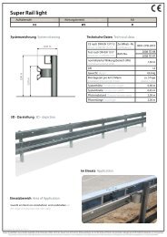
<strong>Saferoad</strong> <strong>RRS</strong><br />
Road Restraint Systems<br />
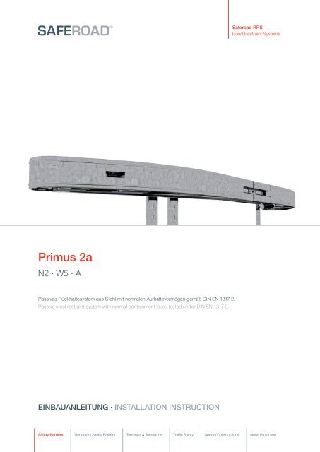
<strong>Primus</strong> <strong>2a</strong><br />
N2 · W5 · A<br />
Passives Rückhaltesystem aus Stahl mit normalen Aufhaltevermögen gemäß DIN EN 1317-2.<br />
Passive steel restraint system with normal containment level, tested under DIN EN 1317-2.<br />
Einbauanleitung · Installation instruction<br />
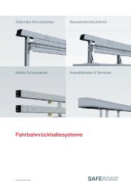
Safety Barriers Temporary Safety Barriers Terminals & Transitions Traffic Safety Special Constructions Noise Protection
Inhalt<br />
TEIL 1<br />
Allgemeine Hinweise zur Montage des Systems<br />
Datenblatt<br />
Allgemeine Information<br />
Technische Informationen<br />
Vorbereitende Maßnahmen<br />
Kontrolle<br />
Überwachungsprotokoll Montage<br />
Anbringung von Zusatzeinrichtungen am System<br />
Reparaturen/Entsorgung/Inspektion und Wartung<br />
Bedarfsanforderung und Anpassung an örtliche Bedingungen<br />
Sonstige Hinweise<br />
TEIL 2<br />
Technische Dokumentation für den Einbau des Systems<br />
Einbaubedingungen<br />
Montagetafel mit Stückliste<br />
3D-Darstellung<br />
TEIL 3<br />
EG-Konformitätserklärung<br />
Content<br />
PART 1<br />
General Information for installation of the system<br />
Data sheet<br />
General information<br />
Technical information<br />
Preparatory measures<br />
Inspection<br />
Installation Controll report<br />
Fitting additional safety devices to the system<br />
Repairs/ Disposing/ Inspection and Maintenance<br />
Necessary requirements and conforming to local conditions<br />
Other information<br />
PART 2<br />
Technical documentation for the installation of the system<br />
Installation conditions<br />
Assembly drawing with components list<br />
3D depiction<br />
PART 3<br />
Declaration of Conformity<br />
© <strong>Saferoad</strong> <strong>RRS</strong> <strong>GmbH</strong>, Stand 2011, Rev. 1
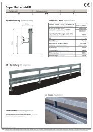
0,68 m<br />
<strong>Saferoad</strong> <strong>RRS</strong><br />
Road Restraint Systems<br />
1,10 m<br />
Pfostenabstand - variabel<br />
distance of posts - variable<br />
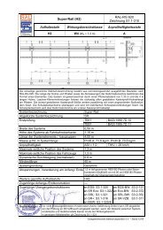
0010-CPD-2009<br />
Erstprüfung<br />
Initial type test (ITT)<br />
EG-Konformitätszertifikat / Hersteller<br />
EU Certificate of Conformity / Manufacturer<br />
Charakteristisches Material des Systems<br />
Characteristic material of the system<br />
Breite des Systems [m]<br />
Construction width<br />
Höhe des Systems ab Fahrbahnoberkante [m]<br />
Construction height from roadway surface level<br />
Länge der Systemelemente / -baugruppen [m]<br />
Length of system elements<br />
Masse je lfd. m Systemlänge [kg/System]<br />
Weight per system<br />
Maximale seitliche Position des Systems [m]<br />
Maximum lateral position of the system<br />
Maximale seitliche Position des Fahrzeugs [m]<br />
Maximum lateral position of the vehicle<br />
Maximale dynamische Durchbiegung [m]<br />
Dynamic deflection<br />
Testlänge [m]<br />
Test length<br />
Geprüfte Systemgründung / -aufstellung<br />
Tested system foundation / installation<br />
Bemerkungen<br />
Remarks<br />
Ergänzende Angaben nach DIN EN 1317-2: 2011-0<br />
Additional information acc. to DIN EN 1317-2:2011-0<br />
Normalisierter Wirkungsbereich [m]<br />
Normalised working width<br />
Normalisierte Wirkungsbereichsklasse Wn<br />
Class of normalised working width<br />
Normalisierte Fahrzeugeindringung [m]<br />
Normalised vehicle intrusion<br />
Klasse der Fahrzeugeindringung VI<br />
Class of vehicle intrusion<br />
Normalisierte dyn. Durchbiegung [m]<br />
Normalised dynamic deflection<br />
TB11: 2002 / D 05/RK TB32: 2002 / D 06/RK<br />
siehe gesonderte Übersicht<br />
see separate overview<br />
S235JR<br />
1.10<br />
0.68<br />
6.43<br />
307.90<br />
1.67<br />
- - -<br />
0.64<br />
6.43<br />
Gerammt rammed<br />
- - -<br />
- - -<br />
- - -<br />
- - -<br />
- - -<br />
Datenblatt · Data sheet<br />
<strong>Primus</strong> <strong>2a</strong><br />
N2 · W5 · A<br />
© 2011 <strong>Saferoad</strong> <strong>RRS</strong> <strong>GmbH</strong>, Please note that forwarding this drawing without permission from <strong>Saferoad</strong> RSS <strong>GmbH</strong> is a<br />
break of copyright. Please contact <strong>Saferoad</strong> RSS <strong>GmbH</strong> for information about corporate licences +49 30 212 491 11.<br />
Weight: 307.90 kg<br />
(Drawing no. K701020-1-1)
Allgemeine Informationen<br />
General Informations<br />
Geltende Vorschriften<br />
• RPS 2009<br />
• DIN EN 1317<br />
• Einsatzempfehlung der BASt<br />
• ZTV-SP 98<br />
• Einschlägige DIN Normen<br />
Symbolbedeutung<br />
Tipp: Hinweise für Arbeitserleichterungen<br />
und effiziente Abläufe.<br />
Anforderungen an das Montagepersonal<br />
Die Montage darf nur durch geschultes und qualifiziertes<br />
Fachpersonal durchgeführt werden. Montagefirmen<br />
erhalten bedarfsgerecht eine projektbegleitende<br />
technische Betreuung durch den Hersteller.<br />
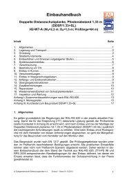
Bestimmungsgemäßer Gebrauch<br />
Das Rückhaltesystem ist zum Einbau in den Straßenverkehrsraum<br />
entsprechend den nationalen Bestimmungen<br />
vorgesehen. Es dient dem Schutz von<br />
Fahrzeuginsassen beim Abkommen eines Fahrzeuges<br />
von der Fahrbahn, dem Schutz Dritter und dem Schutz<br />
von Objekten und ist in Mittel- und Seitentrennstreifenbereichen<br />
sowie am Fahrbahnrand einsetzbar.<br />
Transport<br />
Beim Transport ist Persönliche Schutzausrüstung (PSA<br />
– nach EG Richtlinie 89/686/EWG) entsprechend den<br />
nationalen Bestimmungen zu tragen. Transportieren Sie<br />
die Systemkomponenten mit einem LKW – gegen Verrutschen<br />
der Ladung gesichert – auf die Baustelle. Die<br />
Pakete können bis 2,8 t Gesamtgewicht haben und die<br />
Maße L ≤ 4,35 m x B ≤ 1,00 m x H ≤ 1,00 m. Dementsprechend<br />
sind die Hebezeuge auszuwählen.<br />
Arbeitsschutz<br />
Beim Einbau ist Persönliche Schutzausrüstung (PSA<br />
– nach EG-Richtlinie 89/686/EWG) entsprechend den<br />
nationalen Bestimmungen zu tragen.<br />
Bei der Montage sind die entsprechend Punkt 3.3.2.<br />
angegebenen Montagetoleranzen zu beachten.<br />
Applicable Regulations<br />
• RPS 2009<br />
• DIN EN 1317<br />
• Application recommendations of BASt<br />
• ZTV-SP 98<br />
• Relevant DIN Norms<br />
Symbol Descriptions<br />
Tip: Information on facilitating work processes<br />
and efficient operations.<br />
Requirements of the Assembly Personnel<br />
The installation must only be undertaken by trained<br />
and qualified personnel. Installation firms obtain a<br />
special technical advisor from the manufacturer to<br />
support the project.<br />
Usage Compliance<br />
The Restraint System is designed for installation on<br />
road traffic areas according to national regulations. It is<br />
intended to protect occupants of errant vehicles on the<br />
roadway, to protect third parties and objective and can<br />
be installed in central reserves and side lanes as well as<br />
on verges.<br />
Transport<br />
During transport, personal protective clothing (PPC<br />
in accordance with ER Guideline 89/686/EWG) must<br />
be used. When transporting the systems to the site<br />
by truck, secure the load to prevent slippage. The<br />
packages can weigh up to 2.8t with dimensions of<br />
L ≤ 4.35 m x ≤ 1.00 m x ≤ 1.00 m. Suitable lifting<br />
equipment must be used.<br />
Work Protection<br />
Personal Protective Clothing (PPC in accordance<br />
ER Guideline 89/686/EWG) must be used according<br />
to national regulations.<br />
During installation, the assembly tolerances specified in<br />
section 3.3.2. must be adhered to.<br />
© <strong>Saferoad</strong> <strong>RRS</strong> <strong>GmbH</strong>, Stand 2011, Rev. 1
Technische Informationen<br />
Technical Informations<br />
Schraubverbindungen<br />
Muttern handfest anziehen und dann mit dem Drehmomentschlüssel<br />
festziehen. Sämtliches Verschraubungsmaterial<br />
wird senkrecht zu den zu verbindenden Teilen<br />
angeordnet.<br />
Bolt Connections<br />
Fit nuts manually and then tighten with torque wrench.<br />
All fixtures to be fitted vertically to the connecting parts.<br />
Schraube · Bolt Mmin Mmax<br />
M 10 10 Nm 17 Nm<br />
M 16 70 Nm 140 Nm<br />
Dauerhaftigkeit<br />
Die Mindestschichtdicke für Schrauben und Muttern<br />
beträgt gemäß DIN EN ISO 10684 an den jeweiligen<br />
Messstellen 40 µm.<br />
Durability<br />
The minimum coat thickness for screws and nuts<br />
shall be in accordance with DIN EN ISO 10684 at the<br />
respective measuring points 40 µm.<br />
Teile · Components<br />
Mittelwerte [µm]<br />
Average value<br />
Mindestwerte [µm]<br />
Minimum value<br />
Konstruktionsteile · Construction Components 70 55<br />
Kleinteile (z.B. Decklaschen)<br />
Small Components (e.g. plate)<br />
55 45<br />
Erwartete Dauerhaftigkeit<br />
Ca. 20 Jahre, in Abhängigkeit von der atmosphärischen<br />
Korrosionsbelastung, z.B. Meeresluft,<br />
Industrieluft u.s.w<br />
Expected Durability<br />
Approx. 20 years, depending on atmospheric corrosion<br />
e.g. maritime air, industrial air, etc.<br />
Bodenbedingungen, geeignete Gründungen · Soil coditions, suitable foundations<br />
Bodenklassen<br />
nach<br />
DIN 18196<br />
Soil Class as<br />
per DIN 18196<br />
Bezeichnung<br />
Description<br />
Eigenschaften<br />
Characteristics<br />
Rammen<br />
Post driving<br />
1 – 2 Oberboden, auch fließend<br />
Surface soil also fluid (Humus)<br />
Humus, Mutterboden,<br />
flüssig bis zäh flüssig<br />
top soil, fluid to hardly fluid<br />
nicht möglich; Fundament erstellen<br />
Not possible<br />
3 – 5 Boden leicht lösbar,<br />
mittelschwer, schwer<br />
Ground easily soluble heavy<br />
Sand- und Kiesböden mit Steinanteil<br />
bis 63 mm Korngröße<br />
moderately heavy Sand and gravel<br />
soil with stone content up to 63 mm<br />
grain size<br />
geeignet<br />
possible<br />
6 – 7 Fels<br />
Rock<br />
Felsige Böden<br />
(und ab 63 mm Korngröße)<br />
Rocky ground<br />
(and from 63 mm grain size)<br />
nicht möglich; also bohren,<br />
einsetzen, verfüllen, verdichten<br />
Not possible; therefore bore,<br />
fit, fill, pack<br />
© <strong>Saferoad</strong> <strong>RRS</strong> <strong>GmbH</strong>, Stand 2011, Rev. 1
Vorbereitende Maßnahmen<br />
Preparatory Measures<br />
Schutzausrüstung bereitstellen und anlegen<br />
Stellen Sie folgende Persönliche Schutzausrüstung<br />
bereit und verwenden Sie sie bei den Einbau-Arbeiten:<br />
• Warnkleidung nach EN 471<br />
• Kopf-, Gehör-, Hand- und Fußschutz<br />
Werkzeug bereitstellen<br />
Die hier genannten Werkzeuge sind erforderlich:<br />
• Pfosten-Ramm-Maschine<br />
• Handramme mit Schlauch + Bügel<br />
für Kettenaufnahme<br />
• Pfostenzieher<br />
• Bohrmaschine bis 23 mm mit Bohrern<br />
• Wasserwaage/ Vorschlaghammer<br />
• Drehmomentschlüssel bis 140 Nm mit Stecknüssen<br />
Sie können sich jedoch die Arbeit durch den Einsatz<br />
von alternativen und/oder zusätzlichen Werkzeugen,<br />
Geräten und Maschinen gegebenenfalls komfortabler<br />
gestalten.<br />
Verkehr sichern, Baustelle vorbereiten/einrichten<br />
Führen Sie die an Baustellen üblichen Verkehrssicherungs-Maßnahmen<br />
nach den nationalen Bestimmungen<br />
durch. Die Baustelle muss Platz bieten für:<br />
• ausgelegte Systemkomponenten<br />
• Pfosten-Ramm-Maschine (-Gerät, z. B. Handramme)<br />
• LKWs mit Teleskop-Kran<br />
• Bewegungsfreiheit der Monteure<br />
Liefern, transportieren, auspacken, kontrollieren<br />
Bringen Sie die Systemkomponenten mit dem LKW an<br />
die Einbaustrecke. Packen Sie sie aus und kontrollieren<br />
Sie an Hand der Lieferscheine den Lieferumfang. Bei<br />
Transportschäden und/oder Mangel oder Fehllieferungen<br />
verständigen Sie unverzüglich den Spediteur/<br />
Lieferanten.<br />
Entsorgen Sie das Verpackungsmaterial entsprechend<br />
den örtlich geltenden Abfallentsorgungs-Bestimmungen.<br />
Laden Sie die benötigten Elemente mit dem<br />
Teleskop-Kran neben der Einbaulinie ab.<br />
Allocate and wear protective clothing<br />
Provide the following personal protective clothing and<br />
use during installation works:<br />
• reflective clothing as per EN 471<br />
• head, ear, hand and foot protection<br />
Allocate tools<br />
The following tools are required:<br />
• Post rammer<br />
• manual rammer w. hose and bracket for chain fixture<br />
• Post pully<br />
• drill until 23 mm with drill bits<br />
• level / sledgehammer<br />
• torque key to 140 Nm with sockets<br />
However, you can facilitate the work by using alternative<br />
tools, equipment and machinery as necessary.<br />
Traffic Management, prepare site and set-up<br />
Set up the traffic management measures usually<br />
required by the national regulations. The construction<br />
site must have sufficient space for:<br />
• laid-out system components<br />
• post rammer (or equipment e.g. manual rammer)<br />
• truck with telescope crane<br />
• ample space for the assembly crew<br />
Supply, transport, off loading and delivery check<br />
Bring the system components by truck to the installation<br />
section. Off-load and check that the delivery is as<br />
per the delivery docket. The carrier or supplier has to<br />
be notified immediately if there is any transport damage<br />
or discrepancies with the delivery.<br />
Dispose of the packaging material according to the<br />
applicable local refuse disposals regulations. Lift the<br />
required guardrails with the telescope crane along the<br />
Container with bolts, washers and nuts<br />
© <strong>Saferoad</strong> <strong>RRS</strong> <strong>GmbH</strong>, Stand 2011, Rev. 1
Kontrolle<br />
Inspection<br />
1. Überprüfen der Konstruktion<br />
Nach dem Einbau des Rückhaltesystems prüfen Sie<br />
den festen Sitz aller Schraubverbindungen. Richten Sie<br />
das System ggf. nach. Überzeugen Sie sich, dass die<br />
Strecke der Systemzeichnung entspricht.<br />
2. Einhaltung der Montagetoleranzen<br />
siehe Abbildung unten<br />
3. Abnahmeprotokoll<br />
Halten Sie die Ergebnisse in dem in Anlage<br />
beiliegenden Abnahmeprotokoll fest.<br />
4. Baustelle räumen, System freigeben<br />
• Räumen Sie alles Baumaterial und jeden Abfall weg.<br />
• Führen Sie eine Sichtkontrolle durch, ob die Einbaustrecke<br />
vollkommen frei von Objekten ist.<br />
• Räumen Sie die Absperrungen ab und nach Abnahme<br />
melden Sie dem Betreiber die Fertigstellung des<br />
Systems.<br />
1. Checking the assembly<br />
After the installation of the road restrain system, check<br />
that all bolt fittings are tight. Align the system where<br />
appropriate. Ensure that the section corresponds with<br />
the system drawing.<br />
2. Maintaining the installation tolerances<br />
see tab below<br />
3. Inspection report<br />
Maintain the results in the Inspection Report enclosed<br />
in the attachment.<br />
4. Clear building site, approve system<br />
• Remove all building material and<br />
every piece of refuse.<br />
• Carry out a visible inspection even if the installation<br />
roadway is perfectly free of objects.<br />
• Remove mobile safety barriers and after Inspection,<br />
report completion of the system to the Client.<br />
Einhaltung der Montagetoleranzen · Maintaining the installation tolerances<br />
Bezugsmaß<br />
Reference Measure<br />
Abstand der Pfosten in Längsrichtung<br />
Post spacing in longitudinal direction<br />
Toleranz in cm<br />
Tolerance in cm<br />
(+/-) 10 cm<br />
Anmerkung<br />
Comment<br />
OK Planke<br />
Top of Beam<br />
OK Kastenprofil<br />
Top of the Box Profile<br />
Schrägstellung der Abstandhalter<br />
Oblique position of the Spacer Bar<br />
Abweichung Pfosten aus der Flucht<br />
Post deviation from alignment<br />
Abweichung der Planke aus der Flucht<br />
Beam deviation from alignment<br />
Abweichung des Kastenprofils<br />
aus der Flucht<br />
Box Profile deviation from alignment<br />
(+/-) 10 cm Bezogen auf Geländehöhe<br />
oder OK Kappe am Pfostenpunkt<br />
With reference to height from road surface<br />
or top of curb at the post position<br />
(+/-) 10 cm Bezogen auf Geländehöhe<br />
oder OK Kappe am Pfostenpunkt<br />
With reference to height from road surface<br />
or top of curb at the post position<br />
5° in beide Richtungen<br />
in both directions<br />
3 cm auf 12 m Länge<br />
on 12 m section<br />
3 cm auf 12 m Länge<br />
on 12 m section<br />
3 cm auf 12 m Länge<br />
on 12 m section<br />
© <strong>Saferoad</strong> <strong>RRS</strong> <strong>GmbH</strong>, Stand 2011, Rev. 1
Überwachungsprotokoll<br />
Installation Control Report<br />
Installiertes Rückhaltesystem:<br />
Installed restraint system<br />
1. ausführende Firma<br />
Installation Company<br />
2. Lieferant des Systems<br />
System Supplier<br />
3. Auftraggeber<br />
Client<br />
4. Montageort<br />
Place of Assembling<br />
5.1. Verantwortlicher Montageleiter<br />
Responsible technical supervisor<br />
Monteure<br />
Assembly Team<br />
6. Kontrollbericht<br />
Inspection Report<br />
6.1. Vollständigkeit der Lieferung überprüft<br />
Delivery complete<br />
6.2. Eignung der örtlichen Bedingungen für den Einbau geprüft<br />
Suitability of local conditions for the installation checked<br />
6.3. Montageanweisung befolgt<br />
Installation instruction followed<br />
6.4. Pfosten auf Einbautiefe gerammt<br />
Required installation depth of the posts checked<br />
6.5. Verankerung (bei Plattenpfosten) überprüft<br />
Anchoring (for post with base plate) checked<br />
6.6. Pfostenabstände eingehalten<br />
Post spacing observed<br />
6.7. Stöße der Holme ( Längselemente) überprüft<br />
Joints (longitudinal elements) checked<br />
6.8. Verschraubung auf Vollständigkeit kontrolliert<br />
Bolt connections checked for completeness<br />
6.9. Geforderte Anzugsmomente der Schrauben angebracht<br />
Required torque of the bolts fitted<br />
6.10. Korrekter Einbau aller Elemente erfolgt<br />
Proper installation of all elements followed<br />
6.11. Systemmaße ( Höhen, Abstand zum Fahrbahnrand etc. ) überprüft<br />
System dimension (height, distance to the verge etc.) checked<br />
6.12. Systemmaße ( Höhen, Abstand zum Fahrbahnrand etc. ) überprüft<br />
System dimension (height, distance to the verge etc.) checked<br />
Sonstige Bemerkung:<br />
Other observations<br />
7. Wetterbedingungen:<br />
Weather Conditions<br />
8. Abnahme durch Auftraggeber erfolgt <br />
Approval received from Client<br />
Ort/Datum/Unterschrift<br />
Place/Date/Signature<br />
+/-<br />
© <strong>Saferoad</strong> <strong>RRS</strong> <strong>GmbH</strong>, Stand 2011, Rev. 1
Anbringung von Zusatzeinrichtungen<br />
am System<br />
Fitting additional safety devices<br />
to the system<br />
Für die Anbringung von zusätzlichen Einrichtungen der<br />
Straßenausstattung sind bereits Vorkehrungen an den<br />
Elementen des Systems getroffen worden.<br />
Verkehrszeichen<br />
Die Montage von üblichen Verkehrszeichen ist auf dem<br />
Kastenprofile bzw. auf der verkehrsabgewandten Seite<br />
des Kastenprofils an den Abstandhaltern oder Pfosten<br />
möglich. Für die Befestigung sind die dafür bestimmten<br />
Verkehrszeichenhalter zu benutzen. Dabei ist darauf zu<br />
achten, dass das so montierte Verkehrszeichen nicht in<br />
den Verkehrsraum ragt.<br />
Fußgängerschutz<br />
Für das Anbringen des Fußgängergleitschutzes sind<br />
am Pfosten bereits entsprechende Befestigungspunkte<br />
vorhanden. Gleiches gilt für den Zweiradfahrerschutz<br />
und das Anbringen eines Aufsatzgeländers.<br />
Blendschutzeinrichtungen<br />
Die Montage von Blendschutzeinrichtung ist auf dem<br />
Pfosten grundsätzlich möglich. Dort sind bereits<br />
Bohrungen für die üblichen Befestigungskonstruktionen<br />
vorhanden. Abhängig von der Art des Blendschutzes<br />
können eventuell zusätzliche Bohrungen erforderlich sein.<br />
There are connection features on the system for<br />
attaching additional road safety devices.<br />
Trafic Signs<br />
The assembly of common traffic signs is possible at the<br />
rear of the guardrail beams in the box beam section i.e.<br />
on the spacer bar or posts. For attaching use the specific<br />
traffic sign holders. If there is a danger that certain<br />
traffic signs encroach into the traffic area, consultation<br />
with the manufacturer regarding the positioning of the<br />
traffic sign is required.<br />
Pedestrian Protection<br />
For mounting pedestrian protection rails, corresponding<br />
mounting points are already available at the spacer<br />
bars. The same applies to motorcycle rails and the<br />
fitting of a vertical extension rail.<br />
Anti-glare systems<br />
It is possible to fit anti-glare systems onto the posts.<br />
Bolt holes are already located for the usual connection<br />
fixtures. Extra bolt holes can be made depending on<br />
the type of anti-glare systems.<br />
© <strong>Saferoad</strong> <strong>RRS</strong> <strong>GmbH</strong>, Stand 2011, Rev. 1
Reparaturen, Inspektion<br />
und Wartung<br />
Repairs, Inspection<br />
and Maintenance<br />
Reparaturen<br />
Grundsätzlich sind nur diejenigen Bauteile am System<br />
auszutauschen, die eine bleibende (plastische) Verformung<br />
aufweisen.<br />
Handelt es sich um nur unwesentliche, örtlich begrenzte,<br />
Verformungen an einem Bauteil, so ist ein<br />
Austausch nicht unbedingt erforderlich. Sind Pfosten<br />
verbogen, so müssen diese ausgetauscht werden.<br />
Leichte Schrägstellungen der unverformten Pfosten<br />
können nur dann durch Richten behoben werden, wenn<br />
sich dadurch die Flucht der Längsprofile (Planke) wieder<br />
herstellen lässt.<br />
Ist ein bloßes Richten nicht möglich, und sind mehrere<br />
Bauteile beschädigt, so ist im Bereich der Unfallstelle<br />
das System im modularem 4 Meter Raster komplett<br />
auszutauschen. Dabei sind alle demontierten Verbindungsmittel<br />
(Schrauben) durch neue zu ersetzen. Die<br />
hierbei entstandenen erweiterten Pfostenlöcher sind zu<br />
verfüllen und ausreichend zu verdichten.<br />
Außerdem ist darauf zu achten, dass Beschädigungen<br />
an den verzinkten Oberflächen vermieden werden.<br />
Kleine Fehlstellen an der Zinkoberfläche sind gemäß<br />
DIN 50976 nach sorgfältiger Vorbereitung durch auftragen<br />
einer Zinkstaubbeschichtung nachzubessern.<br />
Überzähliges Material ist vollständig von der Reparaturstelle<br />
zu entfernen.<br />
Reparaturarbeiten können durch jeden Fachbetrieb<br />
problemlos erledigt werden. Die einzelnen Bauteile für<br />
Reparaturarbeiten sind auf dem Markt frei erhältlich,<br />
wobei darauf zu achten ist, dass diese von einem<br />
CE-zertifizierten Hersteller stammen.<br />
Grundsätzlich sind bei der Durchführung von Reparaturarbeiten<br />
die Einbauanleitungen des Herstellers und<br />
die Regelung der ZTV-PS98 Pkt. 2.4.2 zu beachten.<br />
Beschädigte Teile entsorgen / recyclen<br />
Recyceln Sie beschädigte Teile entsprechend den gesetzlichen<br />
und örtlichen Abfallentsorgungs-Vorschriften.<br />
Gefährliche und zu überwachende Substanzen sind<br />
nicht bekannt.<br />
Inspektion und Wartung<br />
Führen Sie alle 12 Monate eine Sichtprüfung durch.<br />
Das System ist wartungsfrei.<br />
Repairs<br />
Basically, you need to replace only those components<br />
that have any residual (plastic) deformation in the<br />
system.<br />
If these are merely minor deformations in one component<br />
that are local in nature, replacement is not really<br />
necessary. However, if posts are bent, they must be<br />
replaced. Minor skews in the non-deformed posts can<br />
be attended to by straightening or turning them, but<br />
only if the alignment of the longitudinal section (plank)<br />
can be restored.<br />
If straightening or turning is not possible, and if more<br />
than one component is damaged, the system in the<br />
damaged section must be replaced completely using<br />
the modular 4 metre sections. In the process, all disassembled<br />
connection fittings (screws) must be replaced<br />
with new ones. The expanded holes in the posts resulting<br />
from this must be filled up and sealed adequately.<br />
Moreover, care must be taken to ensure that the galvanised<br />
surfaces do not get damaged. Minor defective<br />
spots on the galvanised surface must be attended to<br />
by careful preparation with the application of zinc dust<br />
coating in accordance with DIN 50976. Surplus material<br />
must be removed completely from the area that has<br />
been repaired.<br />
Repair work can easily be undertaken by any contractor.<br />
The required components can be purchased on the<br />
open market as long as they have the CE Mark of the<br />
manufacturer.<br />
The repair work must be undertaken according to the<br />
manufacturers installation specifications and the ZDV-<br />
PS98.2.4.2 Regulations.<br />
Dispose/recycled damaged components<br />
Recycle damaged parts according to legal and local<br />
waste disposal regulations. There are no hazardous<br />
and dangerous substances.<br />
Inspection and Maintenance<br />
Run every 12 months, a visual check.<br />
The System is maintenance free.<br />
© <strong>Saferoad</strong> <strong>RRS</strong> <strong>GmbH</strong>, Stand 2011, Rev. 1
Bedarfsanforderungen und<br />
Anpassungen an örtliche<br />
Bedingungen<br />
Necessary requirements and<br />
conforming to local condition<br />
Umbauten des geprüften Rückhaltesystems in anderer<br />
als der zuvor beschriebenen Bauweise sind ohne die<br />
schriftliche Zustimmung des Herstellers nicht zulässig,<br />
da sonst die Zulassung nach DIN EN 1317 erlischt.<br />
Paßstücke<br />
Paßstücke können auf der Arbeitsstelle angefertigt<br />
werden. Dabei sind folgende Bedingungen während der<br />
Herstellung zu beachten:<br />
• Mindestlänge 750 mm auf der Arbeitsstelle<br />
(Profilüberlappung).<br />
• keine Überschreitung des vorgegebenen Pfostenabstands<br />
der Schutzplankenkonstruktion beim Einbau,<br />
• fachgerechtes Trennen mit einer Trennschleifemaschine<br />
oder Säge,<br />
• fachgerechtes Bohren der Verschraubungslöcher,<br />
• fachgerechtes Nachbessern von Schnittstellen und<br />
gebohrten Verschraubungslöchern durch Auftragen<br />
von Zinkstaubeschichtungsstoffen (DIN 50976).<br />
Der Einbau solcher Paßstücke ist auf ein Minimum zu<br />
beschränken. Nur in Ausnahmefällen (z.B. zwischen<br />
2 Brückenbauwerken) sind Paßstücke einzubauen.<br />
Dilatationsstoß<br />
Im Bereich beweglicher Fahrbahnübergänge sind<br />
vorgesehene Dilatationsstöße symmetrisch einzubauen.<br />
Dabei muss beachtet werden, dass mit dem Einbau<br />
der Pfosten mit Fußplatte immer an der Bewegungsfuge<br />
zu beginnen ist. Dilatationsstöße sollen stets fertig<br />
vormontiert auf der Baustelle angeliefert und mit dem<br />
jeweils erforderlichen Pfostenabstand auf dem Bauwerk<br />
montiert werden.<br />
Für die Einstellung der Dilatationsstöße ist die beim<br />
Einbau vorhandene mittlere Bauwerks-temperatur<br />
maßgebend. Die Bewegung der Brücke infolge Temperaturänderung<br />
muss beim Einbau der Pfosten bzw. der<br />
vorgefertigten Anker an der Dehnungsfuge berücksichtigt<br />
werden.<br />
Für die Dilatationsstöße gelten + 10 °C als Nullstellung,<br />
bei der sich die Langlöcher gerade genau decken.<br />
Modifications to the tested restraint system are not permitted<br />
without the written confirmation of the manufacturer<br />
as the approval to DIN EN 1317 would not be met.<br />
Cut pieces<br />
Beams can be cut to fit on site. The following conditions<br />
must be adhered to during production:<br />
• Minimum length 750 mm on site (beam overlap)<br />
• On installation the post spacing of the guardrail<br />
system must not be extended<br />
• Professional cuts using angle grinder or saw<br />
• Professional drilling for bolt holes<br />
• Professional re-work of cuts and drill holes<br />
using zinc spray material ( DIN 50976 )<br />
• Keep the installation of cut pieces to a minimum.<br />
Only use them in exceptional circumstances<br />
such as between 2 bridge structures.<br />
Keep the installation of cut pieces to a minimum. Only<br />
use them in exceptional circumstances such as between<br />
2 bridge structures.<br />
Heat Expansion joint<br />
In section of movable road crossings, Heat Expansion<br />
Joints have to be installed symmetrically. It is important<br />
that the installation of the base-plated posts always<br />
starts at the joint. Heat Expansion Joints should always<br />
be delivered to site fully assembled and installed on the<br />
structure with the correct post spacing.<br />
The middle temperature of the structure at time of<br />
installation is taken when setting the Heat Expansion<br />
Joints. The bridge movement due to temperature<br />
changes must be taken into consideration when<br />
installing the posts i.e. the pre-formed anchors at the<br />
joint. Heat expansion Joint are always ready to preassembled,<br />
delivered and assembled on site with each<br />
required post spacing on the structure.<br />
The Zero Position for overlapping the long bolt hole on<br />
Heat Expansion Joints is generally set at +10°C.<br />
© <strong>Saferoad</strong> <strong>RRS</strong> <strong>GmbH</strong>, Stand 2011, Rev. 1
Hierbei hat der Pfostenabstand genau 4000 mm<br />
(1333 - 1334 - 1333) zu betragen. Der beim Einbau<br />
maßgebende Pfostenabstand ergibt sich somit aus der<br />
Systemlänge des Dilatationsstoßes von 4000 mm ±<br />
Längenänderung.<br />
Die Schrauben in den Dilatationsstößen dürfen nur so<br />
fest angezogen werden, dass keine Behinderung der<br />
Längsbewegung eintreten kann. Die Muttern sind fachgerecht<br />
zu kontern (Mindestanzugsmoment ca. 70 Nm).<br />
Bei Überbaulängen kleiner als 30 m kann auf Dilatationsstöße<br />
verzichtet werden. Auf langen Brücken mit<br />
großen Stützweiten, sollten mindestens alle 100 m<br />
Dilatationsstöße zum Ausgleich der Spannungen vorgesehen<br />
werden.<br />
Abweichender Untergrund<br />
Bei der Verwendung auf nicht ebenerdigen Banketten<br />
ist die Lage der Systemlängselemente der Flucht der<br />
durchlaufenden Schutzeinrichtung anzupassen.<br />
Abweichende Einbauhöhe<br />
Bei Bauwerkskappenhöhen > 7 cm erfolgt der Systemhöhenbezug<br />
zur Bauwerkskappe.<br />
Neigung des Untergrunds<br />
Das System ist auch im geneigten Bankett einsetzbar.<br />
Bei abfallendem Bankett sind ab einer Neigung von<br />
1:20 verlängerte Pfosten in Abhängigkeit der Neigungsstärke<br />
zu verwenden. Wird die zulässige Höhentoleranz<br />
des Schutzplankenholms überschritten, müssen<br />
entsprechende Maßnahmen, wie die Verwendung<br />
eines zweiten untergehängten Schutzplankenholmes<br />
einschließlich Abstandhalters vorgenommen werden.<br />
Grenzen vorgelagerter Stufen<br />
Vor- und nachlaufende Schutzeinrichtungen dürfen sich<br />
in der Aufhaltestufe maximal um eine Klasse unterscheiden.<br />
Radien, Mindestradien<br />
In Kurvenbereichen sind ab einem Radius von 30 m<br />
vorgebogene Schutzplankenholme zu verwenden. Für<br />
Radien von 50 m bis 10 m sind verkürzte Kastenprofile<br />
(z.B. 2 m) zu verwenden, die die entsprechende Radienführung<br />
zulassen. Bei Radien < 10 m sind vorgebogene<br />
Kastenprofile zu verwenden.<br />
Eingeschränkter Wirkungsbereich<br />
Wird der Wirkungsbereich durch bauliche Gegebenheiten<br />
eingeschränkt, ist der Regelabstand zwischen<br />
System und Verkehrsraum entsprechend den Empfehlungen<br />
zur RPS zu reduzieren.<br />
Post spacing must be exactly 4000 mm ( 1333 – 1334 –<br />
1333 ). The post spacing on installation is thereby given<br />
from the system length of the Heat Expansion Joint of<br />
4000 mm ± longitudinal deviation.<br />
The bolts on the Heat Expansion Joint may only be<br />
tightened to the extent that they do not interfere with<br />
the longitudinal movement. The nuts must be countered<br />
professionally (Minimum torque ca. 70 Nm).<br />
For installation lengths less than 30 m heat expansion<br />
joint can be omitted. On longer bridges with large distances<br />
between supports, heat expansion joint should<br />
meet at least every 100 m to balance the tension.<br />
Uneven Ground Conditions<br />
The position of the system on uneven ground conditions<br />
should follow the alignment of the adjacent<br />
systems.<br />
Uneven Installation Situation<br />
When building end kerbs > than 7cm, the height of the<br />
structure has to be in reference with the building.<br />
Underground Slope<br />
The system can also be used on embankments. On<br />
falling embankments with a slope of more than 1:20,<br />
extended posts must be used in relation to the extent<br />
of the slope. If the system height is higher than the<br />
permitted height tolerance, other measures must be<br />
taken such as fitting a 2nd guardrail beam with spacer<br />
bar underneath.<br />
Containment Level of adjacent systems<br />
The containment levels of adjacent safety barrier systems<br />
may only vary by one class.<br />
Radius, minimum radius<br />
In curved road sections of more than radius 30 m, prebend<br />
radius guardrails must be used. For radii between<br />
50m and 10m, shorter box beams (e.g. 2 m) must be<br />
used which meet the curvature. For radii < 10 m prebend<br />
box beams must be used.<br />
Restricted Working Width<br />
It is a recommendation by in the RPS that if the working<br />
width is limited due to structural obstructions, the regulatory<br />
set-back between the safety barrier system and<br />
traffic area should be reduced accordingly.<br />
© <strong>Saferoad</strong> <strong>RRS</strong> <strong>GmbH</strong>, Stand 2011, Rev. 1
Abweichender Höhenbezug<br />
Wird das System in Plankenflucht < 10 cm zur Bauwerkskappenkante<br />
montiert und ist die Höhendifferenz<br />
der Kappe zur FOK > 10 cm, ist der Systembezug auf<br />
die FOK auszurichten.<br />
Anpassung des Pfostenabstandes<br />
Der Pfostenabstand darf grundsätzlich nicht überschritten<br />
werden. Sollten die Baulichkeiten (z.B. Ablaufschächte)<br />
einen regelmäßigen Abstand nicht zulassen,<br />
darf das Pfostenraster mur verkürzt werden.<br />
Ausführung von Verschwenkungen<br />
Ist auf Grund der baulichen Situation eine seitliche<br />
Verschwenkung des Systems notwendig, sollte diese<br />
im Verhältnis von 1:24 ausgeführt werden.<br />
Änderung von Systemteilen<br />
Änderungen an Systemteilen sind mit dem Hersteller<br />
abzustimmen. Für geringfügige Änderungen wie Passstücke<br />
und zusätzliche Bohrungen sind die Regelungen<br />
der ZTV-PS98 Punkt 2.4.2 zu beachten.<br />
Uneven Height Reference<br />
If the barrier alignment of the system is installed<br />
< 10 cm from the edge of curb on the structure and<br />
the height from finished road level to the curb is<br />
> 10 cm, then the height of the system is in respect<br />
of the finished road level.<br />
Adjustment of the post spacing<br />
In principle, the distance between the posts are not<br />
exceeded. If the site conditions do not allow a regular<br />
distance, the post spacing may be reduced.<br />
Installation of Flared Ends<br />
If there are structural conditions where the terminal<br />
ends must be flared back, the ratio should be 1:24.<br />
Modification of System Components<br />
Modifications to the system’s components must be<br />
agreed with the manufacturer. For minor modifications<br />
such as cut pieces and additional drill holes, the ZTV-<br />
PS98 Regulations, section 2.4.2 must be adhered to.<br />
Sonstige Hinweise<br />
Other Information<br />
Auf Grund der abgestuften Systemhöhe ist das System<br />
problemlos übersteigbar.<br />
As the system height for the guardrail beam is stepped,<br />
it can easily be mounted.<br />
© <strong>Saferoad</strong> <strong>RRS</strong> <strong>GmbH</strong>, Stand 2011, Rev. 1
Einbaubedingungen<br />
Installation conditions<br />
Beim Einbau des Systems sind die nachfolgenden Parameter<br />
zu prüfen und nach Möglichkeit einzuhalten. Dabei<br />
ist zunächst durch Messungen vor Ort festzustellen:<br />
A = Abstand Systemvorderkante vom Straßenrand – in<br />
der Regel A = 0,50 m. (Eventuell ist A an die Flucht<br />
der übrigen Schutzeinrichtung anzupassen.)<br />
B = Länge des Hindernisses in (m).<br />
C = Abstand des Hindernisses (Vorderkante) vom befestigten<br />
Straßenrand in (m).<br />
D = Abstand des Hindernisses (Hinterkante) vom befestigten<br />
Straßenrand in (m).<br />
E = Entfernung der Böschungskante vom befestigen<br />
Straßenrand.<br />
When installing the system, the following paramaters<br />
must be checked and the stated limit values observed, as<br />
far as possible. In doing so, one must initially determine:<br />
A = Distance of the system’s front edge from the street<br />
kerb – usually A = 0.50 m. ( It may be that A must be<br />
adapted to the alignment of the remaining protective<br />
installation.)<br />
B = Length of the obstacle in (m).<br />
C = Distance of the obstacle (front edge) from the fixed<br />
street kerb in (m).<br />
D = Distance of the obstacle (back edge) from the fixed<br />
street kerb in (m).<br />
E = Distance of the slope edge from the fixed street<br />
edge.<br />
3.1. Standardausführung<br />
In der Standardausführung hat das System eine Länge<br />
von L = 6,40 m und besteht aus zwei spiegelbildlich zueinander<br />
angeordneten Halbelementen. Diese werden auf<br />
je zwei getrennten C - Pfosten so aufgeschraubt, dass<br />
das System symmetrisch zum Hindernis steht.<br />
3.1. Standard version<br />
In the standard version, the system has a length of L =<br />
6.40 m and consists of two half-elements arranged in<br />
mirror symmetry to one another. These are both respectively<br />
screwed onto two separated C-posts in such a way<br />
that the system stands symmetrically to the obstacle.<br />
Befinden sich die Maße im Rahmen der vorgegebenen<br />
Grenzwerte, so kann das System in<br />
der Standardausführung Fig. 1 errichtet werden.<br />
Sind die Maße außerhalb der Grenzwerte so<br />
muss das System in der gestreckten Ausführung<br />
Fig. 2 errichtet werden.<br />
If the dimensions are within the pre-defined<br />
threshold values, the system can be set up in<br />
the standard version (see Fig. 1). If the dimensions<br />
are outside the threshold values, the system<br />
must be set up using the stretched version (see<br />
Fig. 2).<br />
B ≤ 2.00 m<br />
C ≥ 1.00 m<br />
D ≤ 2.50 m<br />
A<br />
L = 6.40 m<br />
© <strong>Saferoad</strong> <strong>RRS</strong> <strong>GmbH</strong>, Stand 2011, Rev. 1
3.2. Gestreckte Ausführung<br />
Sind breitere Hindernisse vorhanden B > 2m oder stehen<br />
diese weiter vom Straßenrand entfernt D > 2,5 m, so<br />
ist das System mit einer Doppelholm-Verlängerung (L V<br />
)<br />
symmetrisch zur Mittelachse zu versehen.<br />
3.2. Stretched version<br />
If wider obstacles are present (B > 2m) or these are located<br />
further away from the street kerb (D > 2.5 m), the<br />
system must be given a double-beam extension ( L v<br />
)<br />
symmetrically to the middle axis.<br />
L 3l<br />
B<br />
L 3r<br />
D<br />
≤ 5<br />
D<br />
L V<br />
3.20 m 3.20 m<br />
Die Werte der Tab. 1 können sich reduzieren, wenn der<br />
Abstand des Systems vom Straßenrand (Maß A) vergrößert<br />
wird, das System also näher an das Hindernis<br />
heranrückt.<br />
The values of Tab. 1 can reduce if the distance of the<br />
system from the street kerb (Measurement A) is increased,<br />
i.e. the system is moved closer to the obstacle.<br />
D [in m] 2.5 3.0 3.5 4.0 5.0<br />
L V<br />
[in m] 4.0 8.0 12.0 16.0 20.0<br />
L 3<br />
[in m] 4.0 5.6 7.6 10.0 13.0<br />
1. Länge ( D ) und Breite ( B ) der Hindernisse durch Messungen<br />
bestimmen.<br />
2. Maß A mit 0,5m oder in Flucht mit anderen Schutzeinrichtungen<br />
festlegen.<br />
3. Den Abstand des <strong>Primus</strong> vom äußeren Hindernis (Maß<br />
L 3<br />
) nach Tab. 1 bestimmen. Der Abstand L 3<br />
kann links<br />
und rechts jeweils verschieden sein.<br />
1. Determine length (D) and width (B) of the obstacles by<br />
means of measurements.<br />
2. Set Measurement A at 0.5 m or in alignment with other<br />
protective installations.<br />
3. Determine the distance of the <strong>Primus</strong> from the external<br />
obstacle (Measurement L 3<br />
) acc. to Tab. 1. L 3<br />
can be<br />
different on the left side and on the right side respectively.<br />
Die Länge L V<br />
ist nach folgender Regel zu bestimmen:<br />
The length Lv must be determined according to the following<br />
rule:<br />
L V<br />
= B + L 3l<br />
+ L 3r<br />
- 6.40 [in m]<br />
Die Länge L 3<br />
ist jeweils vom Maß D abhängig, kann also<br />
am rechten L 3r<br />
bzw. linken L 3l<br />
Enden verschieden sein.<br />
Für die Holm-Verlängerung sind ausschließlich Bauelemente<br />
nach Zeichnung Z.20.13 zu verwenden.<br />
The respective length (L 3<br />
) is dependent on Measurement<br />
D; it can thus be different at the right end L 3r<br />
or at the<br />
left end L 3l<br />
respectively. For the extension of the beam<br />
it is exclusively construction elements according to the<br />
drawing Z.20.13 which must be used.<br />
© <strong>Saferoad</strong> <strong>RRS</strong> <strong>GmbH</strong>, Stand 2011, Rev. 1
<strong>Saferoad</strong> <strong>RRS</strong><br />
Road Restraint Systems<br />
Stückliste · Components list<br />
0010-CPD-2009<br />
Name<br />
Artikel Nr.<br />
Part no.<br />
Anzahl/Stück<br />
Number/Unit<br />
<strong>Primus</strong> <strong>2a</strong> Einzelkörper · Chassis 492508/2 2<br />
Pfosten · Post C 125 1900 mm 406102/0 4<br />
<strong>Primus</strong> Bügel · Bracket 492510/0 1<br />
Decklasche · Plate 2x M16 492545/0 1<br />
HRK-Schraube · Bolt M16x27 040.00 12<br />
HRK-Schraube · Bolt M16x40 040.01 12<br />
Scheibe · Washer Ø 18 040.30 16<br />
Scheibe · Washer 40x18x4 mm 040.31 8<br />
Montagetafel · Assembly drawing<br />
MegaRail <strong>Primus</strong> <strong>2a</strong><br />
N2 · W5 · A<br />
© 2011 <strong>Saferoad</strong> <strong>RRS</strong> <strong>GmbH</strong>, Please note that forwarding this drawing without permission from <strong>Saferoad</strong> RSS <strong>GmbH</strong> is a<br />
break of copyright. Please contact <strong>Saferoad</strong> RSS <strong>GmbH</strong> for information about corporate licences +49 30 212 491 11.<br />
Weight: 307,90 kg<br />
(Drawing no. K701020-3-1)
<strong>Saferoad</strong> <strong>RRS</strong><br />
Road Restraint Systems<br />
Vorderansicht · Front view<br />
Rückansicht · Rear view<br />
0010-CPD-2009<br />
3D Darstellung · 3D depiction<br />
MegaRail <strong>Primus</strong> <strong>2a</strong> bs<br />
N2 · W5 · A<br />
© 2011 <strong>Saferoad</strong> <strong>RRS</strong> <strong>GmbH</strong>, Please note that forwarding this drawing without permission from <strong>Saferoad</strong> RSS <strong>GmbH</strong> is a<br />
break of copyright. Please contact <strong>Saferoad</strong> RSS <strong>GmbH</strong> for information about corporate licences +49 30 212 491 11.<br />
Weight: 307,90 kg<br />
(Drawing no. K701020-2-1)
EG-Konformitätserklärung · EU-Declaration of Conformity<br />
nach Bauproduktenrichtlinie 89/106/EWG für das Rückhaltesystem<br />
In accordance with building product code 89/106/EWG for restraining systems<br />
<strong>Primus</strong> <strong>2a</strong><br />
0531<br />
Der Hersteller<br />
Manufacturer<br />
erklärt hiermit, dass folgendes Produkt:<br />
declares herewith that the following product<br />
Outimex AG<br />
Landshuter Straße 1,<br />
10779 Berlin/ Germany<br />
„<strong>Primus</strong> <strong>2a</strong>“<br />
Fahrzeugrückhaltesystem im Straßenverkehrsraum<br />
Road Restraint System<br />
den Bestimmungen der oben gekennzeichneten Richtlinie entspricht.<br />
complies with the above named Regulations.<br />
Zertifizierungsstelle<br />
Certification Body<br />
EU-Notifizierungsnummer<br />
EU-Notification number<br />
Beschreibung des Produkts<br />
Product Description<br />
Verwendungshinweis<br />
Application Note<br />
EG-Konformitätszertifikat-Nr.<br />
EU-Certificate of Conformity No.<br />
Folgende Europäische Normen wurden angewandt<br />
The following European Norms apply<br />
TÜV SÜD SZA Österreich<br />
Technische Prüf-<strong>GmbH</strong><br />
Arsenal Objekt 207<br />
1030 Vienna/ Austria<br />
0531<br />
Aufhaltestufe Containment Level N2<br />
Anprallheftigkeit Impact Severity A<br />
Wirkungsbereich Working Width W5<br />
Dynamische Durchbiegung Dynamic Deflection 0,6 m<br />
Das Rückhaltesystem „<strong>Primus</strong> <strong>2a</strong>“ ist ein Anfahrschutz<br />
für einzelne Hindernisse im Straßenraum. Als kurze<br />
Schutzeinrichtung kommt es bevorzugt dort zum<br />
Einsatz, wo die örtlichen Verhältnisse keine durchgehenden<br />
Schutzeinrichtungen zulassen<br />
The restraint system “<strong>Primus</strong> <strong>2a</strong>” is an impact protection<br />
system for individual hazards in verges. As a short<br />
safety system, its is preferably used in such locations<br />
where it is not possible to use a continuous installation.<br />
0010 - CPD - 2009<br />
EN 1317 Teil 1,2 und 5<br />
Hilmar Förster<br />
Technischer Vorstand<br />
Technical Menber of the Board<br />
Holger Klostermeier<br />
Leiter F&E<br />
Head of R&D
<strong>Saferoad</strong> <strong>RRS</strong> <strong>GmbH</strong><br />
Sales International<br />
<strong>Saferoad</strong> <strong>RRS</strong> <strong>GmbH</strong><br />
Sales Germany<br />
Landshuter Straße 1<br />
10779 Berlin<br />
T + 49 30 21 24 91 11<br />
F + 49 30 21 24 91 50<br />
berlin@saferoad.com<br />
Bongard-und-Lind-Straße 1<br />
56414 Weroth<br />
T + 49 6435 90 80 0<br />
F + 49 6435 90 80 110<br />
weroth@saferoad.com<br />
© <strong>Saferoad</strong> <strong>RRS</strong> <strong>GmbH</strong>, Stand 2011, Rev. 1<br />
www.saferoad-rrs.com<br />
www.produktmatrix.de<br />
www.downloadhub.de