WellChrom Filter-Photometer K-2001 Filterphotometer K-2001 ...
WellChrom Filter-Photometer K-2001 Filterphotometer K-2001 ...
WellChrom Filter-Photometer K-2001 Filterphotometer K-2001 ...

Erfolgreiche ePaper selbst erstellen
Machen Sie aus Ihren PDF Publikationen ein blätterbares Flipbook mit unserer einzigartigen Google optimierten e-Paper Software.
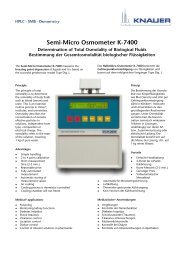
<strong>WellChrom</strong><br />
<strong>Filter</strong>-<strong>Photometer</strong> K-<strong>2001</strong><br />
<strong>Filter</strong>photometer K-<strong>2001</strong><br />
Handbuch / User Manual<br />
V7561, 06/<strong>2001</strong><br />
Wissenschaftliche Gerätebau Dr. Ing. Herbert Knauer GmbH Hegauer Weg 38 D-463 Berlin GERMANY<br />
Telefon: +49-(0)30 80 97 27-0 Fax: +49-(0)30 80 50 0 Email: info@knauer.net www.knauer.net
CONTENTS<br />
Using this Manual......................................................................................4<br />
Conventions in this manual..................................................................4<br />
SOP´s in this manual ...........................................................................5<br />
The <strong>Filter</strong>-<strong>Photometer</strong> K-<strong>2001</strong> ...................................................................6<br />
General Description .............................................................................6<br />
Optical Path of the <strong>Filter</strong>-<strong>Photometer</strong> K-<strong>2001</strong> .....................................7<br />
Preparing the <strong>Filter</strong>-<strong>Photometer</strong> K-<strong>2001</strong> for Operation............................7<br />
Unpacking.............................................................................................7<br />
Standard delivery .................................................................................7<br />
Front Panel Controls ............................................................................8<br />
Front View of the <strong>Filter</strong>-<strong>Photometer</strong> K-<strong>2001</strong> ..................................8<br />
Function of Foil Keys ......................................................................8<br />
Rear view ........................................................................................9<br />
Power supply, ON/OFF, Selftest .........................................................9<br />
Operating the <strong>Filter</strong> <strong>Photometer</strong>..............................................................10<br />
Internal Software Structure ................................................................10<br />
Installation of the Flow Cell................................................................14<br />
Capillary Connection to a HPLC System ..........................................14<br />
Direct Control of the <strong>Filter</strong>-<strong>Photometer</strong> K-<strong>2001</strong>.................................15<br />
Time programmed Chromatograms..................................................16<br />
Entering a Program.......................................................................16<br />
Running a Program ......................................................................17<br />
Connecting other Instruments to the <strong>Filter</strong>-<strong>Photometer</strong> K-<strong>2001</strong>............17<br />
Using the remote control socket........................................................17<br />
Connections of the remote control socket ...................................17<br />
Assembling plug strips..................................................................19<br />
Software Control of the <strong>Filter</strong>-<strong>Photometer</strong> K-<strong>2001</strong>............................19<br />
RS 232 Serial Interface ................................................................20<br />
Simple Maintenance................................................................................21<br />
Control of the lamp’s functionality......................................................21<br />
Changing the lamp.............................................................................21<br />
Cleaning the flow cell .........................................................................23<br />
Analytical flow cells.......................................................................23<br />
Preparative flow cells....................................................................24<br />
Adjusting the path length of the preparative flow cells......................24<br />
Flow cells with fiber optical connectors .............................................25<br />
Trouble shooting......................................................................................26<br />
Error messages and their reasons ....................................................26<br />
Spare parts and accessories ..................................................................27<br />
Flow cells for the <strong>Filter</strong>-<strong>Photometer</strong> K-<strong>2001</strong>......................................27<br />
Analytical Flow Cells.....................................................................27<br />
Preparative Flow Cells..................................................................27<br />
U-Z View Micro Flow Cells ........................................................27<br />
Spare Parts.........................................................................................27<br />
Technical Data.........................................................................................28<br />
Declaration of conformity.........................................................................29<br />
Guarantee statement...............................................................................30
INHALT<br />
Zur Benutzung des Handbuches ............................................................31<br />
Konventionen in diesem Handbuch ..................................................31<br />
SOP´s in diesem Handbuch ..............................................................32<br />
Das <strong>Filter</strong>photometer K-<strong>2001</strong>...................................................................33<br />
Allgemeine Beschreibung..................................................................33<br />
Optischer Weg im <strong>Filter</strong>photometer K-<strong>2001</strong>......................................34<br />
Inbetriebnahme des <strong>Filter</strong>photometers K-<strong>2001</strong> ....................................35<br />
Auspacken..........................................................................................35<br />
Standardauslieferung.........................................................................35<br />
Steuerelemente des <strong>Filter</strong>photometers K-<strong>2001</strong>................................35<br />
Frontansicht ..................................................................................35<br />
Funktion der Folientastatur...........................................................36<br />
Rückansicht ..................................................................................36<br />
Stromversorgung, Ein/Aus, Autotest .................................................37<br />
Betrieb des <strong>Filter</strong>photometers.................................................................38<br />
Aufbau der internen Software............................................................38<br />
Installation der Messzelle ..................................................................41<br />
Kapillaranschluss an ein HPLC-System ...........................................42<br />
Direkte Steuerung des <strong>Filter</strong>photometers K-<strong>2001</strong> ............................43<br />
Zeitprogrammierte Chromatogrammaufnahme ................................44<br />
Programm-Eingabe ......................................................................44<br />
Programm-Ausführung .................................................................44<br />
Verbindung anderer Geräte mit dem <strong>Filter</strong>photometer K-<strong>2001</strong>.............45<br />
Verwendung der Fernsteuerungsleiste .............................................45<br />
Belegung der Fernsteuerungsanschlussleiste ............................45<br />
Montage der WAGO-Anschlussstecker.......................................47<br />
Softwaresteuerung des <strong>Filter</strong>photometers K-<strong>2001</strong> ...........................47<br />
RS 232 Serielle Schnittstelle........................................................48<br />
Einfache Wartung....................................................................................49<br />
Kontrolle der Lampenfunktion............................................................49<br />
Lampenwechsel .................................................................................49<br />
Messzellenreinigung ..........................................................................51<br />
Analytische Messzellen ................................................................51<br />
Präparative Messzellen ................................................................52<br />
Festlegung der Länge präparativer Messzellen................................52<br />
Messzellen mit Lichtleiteranschluss ..................................................53<br />
Fehlermeldungen und ihre Ursachen .....................................................54<br />
Ersatzteile und Zubehör ..........................................................................55<br />
Messzellen für das <strong>Filter</strong>photometer K-<strong>2001</strong>....................................55<br />
Analytische Durchflusszellen........................................................55<br />
Präparative Durchflusszellen........................................................55<br />
U-Z View Mikro-Durchflusszellen..............................................55<br />
Ersatzteile...........................................................................................55<br />
Technische Daten ...................................................................................56<br />
Konformitätserklärung .............................................................................57<br />
Garantiebedingungen..............................................................................58
4 Using this Manual<br />
Using this Manual<br />
This manual refers to the <strong>WellChrom</strong> <strong>Filter</strong>-<strong>Photometer</strong> K-<strong>2001</strong><br />
Firmware Revision 1.06 or higher. It is valid for any combination with<br />
analytical flow cells order number A 4061, A 4062, A 4063, A 4065,<br />
preparative flow cells order number A 4066, A 4067, A 4068, A 4069<br />
and all UZ View micro flow cells in standard and fiber optic version.<br />
Conventions in this manual<br />
Arrows like this: , used in block diagrams, indicate that the<br />
user is asked to press the corresponding arrow keys. The operation of<br />
arrow keys is defined as follows:<br />
Cursor right: up: down: left: .<br />
Important Hints are marked by the marginal hand symbol.<br />
Special Warnings are indicated by the marginal warning sign and<br />
printed in bold letters.<br />
The marginal lamp symbol indicates helpful advice’s.
Using this Manual 5<br />
SOP´s in this manual<br />
The Standard Operating Procedures (SOP) provided with this manual<br />
offer a convenient way of structuring complex tasks in the operation of<br />
your <strong>Filter</strong>-<strong>Photometer</strong> K-<strong>2001</strong>. They include step-by-step instructions<br />
leading the user through all routine tasks during operation. They can<br />
be used for documentation purposes and be copied, applied signed,<br />
and filed in order to document the performance of the instrument.<br />
Please operate the instrument and all accessories according to<br />
instructions and SOP´s in this manual. This ensures proper<br />
results and longevity of your equipment.<br />
SOP 1 Installation of the Flow Cell.............................................14<br />
SOP 2 Capillary connections......................................................14<br />
SOP 3 WAGO plug strip assembling..........................................19<br />
SOP 4 Changing the deuterium lamp. .......................................22<br />
SOP 5 Changing the halogen tungsten lamp.............................22<br />
SOP 6 Purging the Flow Cell......................................................23<br />
SOP 7 Cleaning an analytical flow cell.......................................23<br />
SOP 8 Cleaning a preparative flow cell......................................24<br />
SOP 9 Changing the path length................................................24
6 The <strong>Filter</strong>-<strong>Photometer</strong> K-<strong>2001</strong><br />
The <strong>Filter</strong>-<strong>Photometer</strong> K-<strong>2001</strong><br />
General Description<br />
The <strong>WellChrom</strong> <strong>Filter</strong>-<strong>Photometer</strong> K-<strong>2001</strong>is a valuable new detector,<br />
especially developed for routine measurements. The <strong>Filter</strong>-<strong>Photometer</strong><br />
K-<strong>2001</strong>satisfies all GLP requirements of a regulated laboratory.<br />
The instrument is delivered in its standard version with a deuterium<br />
lamp as well as with 4 filters for the wavelengt`s 200, 220, 254, and<br />
280 nm. Optional a tungsten-halogen lamp is available. Additional two<br />
further wavelength filters of your choice can be build in.<br />
A rich palette of flow cells available for the KNAUER photometers,<br />
ranging from cells for Nano-HPLC with flow rates < 10 nL/min to<br />
preparative cells for up to 10 l/min, make the photometer K–<strong>2001</strong><br />
highly flexible in the full range of LC applications.<br />
Moreover, a version of the <strong>Filter</strong>-<strong>Photometer</strong> K-<strong>2001</strong>equipped with<br />
fiber optical connectors of the cell is available. This enables the spatial<br />
separation of detector and flow cell and thus the use of these<br />
instruments in hazardous locations.<br />
After powering up the <strong>WellChrom</strong> <strong>Filter</strong>-<strong>Photometer</strong> K-<strong>2001</strong>performs a<br />
self test automatically.<br />
The high sensitive detector is marked by its excellent low noise<br />
(+ 1 x 10 -5 AU) and also by a low baseline drift of 5 x 10 -5 AU/h. The<br />
Autozero range is full scale.<br />
The clear foilpad enables you to activate all basic functions in an easily<br />
to learn way. Furthermore you can enter, save, and run a time program<br />
for changing the filter. 10 program lines are available. The program can<br />
be executed as often as you want.<br />
The control of the <strong>Filter</strong>-<strong>Photometer</strong> and the data collection occur<br />
digitally, to ensure a trouble free working of the instrument. Also an<br />
adjustable analog input and the option for an analog remote control are<br />
available.
Preparing the <strong>Filter</strong>-<strong>Photometer</strong> K-<strong>2001</strong> for Operation 7<br />
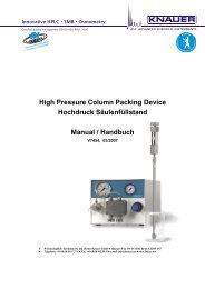
Optical Path of the <strong>Filter</strong>-<strong>Photometer</strong> K-<strong>2001</strong><br />
6 5 4 2 1<br />
7 3<br />
1. Lamp (deuterium or halogen) 2. Lens<br />
3. Exchangeable filter 4. Half transparent mirror<br />
5. Flow cell 6. Photo diode<br />
7. Reference photo diode<br />
Fig. 1 Optical Path of the <strong>Filter</strong>-<strong>Photometer</strong> K-<strong>2001</strong><br />
The light emitted from the lamp (1) is focussed by the lens(2). The<br />
exchangeable filter (3) fades out the desired wavelength. The beam is<br />
then splitted by a half transparent mirror (4). One part beam delivers the<br />
reference signal (7) and the other after pathing the flow cell (5) the<br />
measurement signal (6).<br />
Preparing the <strong>Filter</strong>-<strong>Photometer</strong> K-<strong>2001</strong> for<br />
Operation<br />
Unpacking<br />
After unpacking, please check the device and accessories thoroughly<br />
for any damage that may have occurred during transport. If<br />
necessary, put forward any claim for damages to the carrier.<br />
Use list “Standard delivery” and check that the <strong>Filter</strong>-<strong>Photometer</strong><br />
K-<strong>2001</strong>delivery is complete. Please contact our service department if<br />
you miss something or if you need support. Please fill out the<br />
guarantee registration card and return it to us immediately.<br />
Remove the protection foils from the display and from the capillary inlet<br />
and outlet respectively.<br />
Standard delivery<br />
<strong>WellChrom</strong> Spectro <strong>Photometer</strong> K-2501 without cell<br />
Operation Manual<br />
Power Supply Cable 230 V<br />
RS-232 Cable<br />
Integrator Cable<br />
Plug Strips with Connectors<br />
Analog Connection Cable
8 Preparing the <strong>Filter</strong>-<strong>Photometer</strong> K-<strong>2001</strong> for Operation<br />
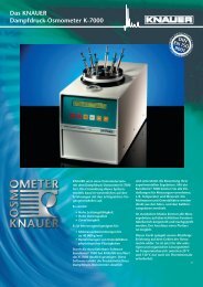
Front Panel Controls<br />
Front View of the <strong>Filter</strong>-<strong>Photometer</strong> K-<strong>2001</strong><br />
1. Display information<br />
2. Foil key area<br />
3. Knurled cell screws<br />
4. Flow cell housing<br />
5. Flow cell cradle<br />
6. Outlet<br />
7. Flow cell<br />
8. Path length of cell<br />
9. Inlet<br />
1<br />
2<br />
3<br />
4<br />
10<br />
5<br />
9 8 7 6<br />
Fig. 2<br />
Front Panel Elements of <strong>Photometer</strong> and Flow Cell<br />
Function of Foil Keys<br />
The foil key area (2) in Fig. 2 „Front panel of the <strong>Filter</strong>-<strong>Photometer</strong><br />
K-<strong>2001</strong>“ consists of an AUTOZERO key and four arrow keys.<br />
AUTOZERO<br />
Pushing this button will adjust the baseline. Usually the button should<br />
be pressed shortly before starting a chromatographic run. From any<br />
displayed menus the display returns to the SIGNAL-menu.<br />
Arrow Keys<br />
Use the yellow arrow keys „right“ or “left“ to move and to position<br />
the cursor on the display as well as to confirm entered or selected<br />
values.<br />
Using the yellow arrow keys „up“ or „down“ you can change the<br />
selected parameter or the available options of it.
Preparing the <strong>Filter</strong>-<strong>Photometer</strong> K-<strong>2001</strong> for Operation 9<br />
Rear view<br />
1<br />
2<br />
3<br />
4<br />
5<br />
6<br />
7<br />
Fig. 3 Rear view of the <strong>Filter</strong>-<strong>Photometer</strong> K-<strong>2001</strong><br />
1 Analog output (to recorder or integrator)<br />
2 Indication of the input voltage (see Abb. 4)<br />
3 ON/OFF switch<br />
4 RS-232 Interface<br />
5 Terminal strip Remote connections<br />
6 Power connector<br />
7 Serial number<br />
Power supply, ON/OFF, Selftest<br />
The <strong>Filter</strong>-<strong>Photometer</strong> K-<strong>2001</strong> operates with 115 or 230 V AC of 47-<br />
63 Hz. The setting is done by the manufacturer on customers request.<br />
The standard setting is 230 V. If there is on any reasons the need of a<br />
change, please contact our service department. The actual setting is<br />
indicated on the rear panel of the instrument (Abb. 4).<br />
Fig. 4<br />
Indication of the input voltage<br />
Make certain that the correct voltage has been set on the rear<br />
panel of the instrument, the power supply is grounded and a<br />
corresponding 3-pole power cable is used.<br />
Connect the photometer to the power supply and switch on the instrument.<br />
The power switch is on the rear panel, see Abb. 3 on page 36.
10 Operating the <strong>Filter</strong> <strong>Photometer</strong><br />
After switching ON the display (item 1 in Fig. 2 on page 8) presents<br />
for a short time information’s concerning the instrument version and<br />
number:<br />
*KNAUER V 2.3<br />
MINI-FIPHO<br />
Any powering up the instrument includes a check of the electronics and<br />
an Autozero. Prior to this the lamp is heated to the working temperature<br />
for about 20 seconds indicated by the following display:<br />
signal: -.----<br />
:254 t:0.2 HEA<br />
The start routine will be finished by an automatically Autozero. Now<br />
the <strong>Filter</strong>-<strong>Photometer</strong> is ready to work, showing the display:<br />
signal: 0.0000<br />
:254 t:0.2 ON<br />
Operating the <strong>Filter</strong> <strong>Photometer</strong><br />
Internal Software Structure<br />
The software is divided in various menus, each of which allows<br />
particular settings and operational modes. You reach the single menus<br />
by positioning the cursor on the rhombus field followed by pressing<br />
the or keys. As indicated in Abb. 5, the menus will be called up in<br />
an endless loop.<br />
The single menus will be described in detail. Inside of any menu the<br />
cursor can be moved to the next or predecessing field using the<br />
or keys respectively. There it is possible to increase or decrease<br />
the corresponding parameter settings by help of the or keys. In<br />
some cases you can scroll with the or keys through the available<br />
options. Moving to an other entry field using the or keys<br />
respectively the entered changes will be confirmed.
Operating the <strong>Filter</strong> <strong>Photometer</strong> 11<br />
signal: 0.0000<br />
:254 t:0.2 ON<br />
UNITS signal: au<br />
:nm t:s<br />
GLP S/N:00047755<br />
01 00962.0h 101<br />
PROG 000.00-254<br />
go 000.00-***<br />
A-IN Set-Zero<br />
actual: 000nm<br />
LAMP:<br />
Deuterium<br />
INT sig:0.6543<br />
1/8 ref:0.3848<br />
ANALOG OUT: [au]<br />
full scale:1e-0<br />
EXT. CONTROL:<br />
keyboard<br />
Fig. 5 Menu sequence of the <strong>Filter</strong>-<strong>Photometer</strong> K-<strong>2001</strong><br />
The SIGNAL menu<br />
signal: 0.0000<br />
:254 t:0.2 ON<br />
The signal or main menu contains the data signal intensity signal:,<br />
wavelength :, time constant t: and the lamp status.<br />
The actual measured signal value is shown in a fixed point manner<br />
with four digits. The measurement wavelength : can be selected out<br />
of the standard values 200, 220, 254, 280 nm, and if choosen of your<br />
optional filters.<br />
Using a time constant you can achieve a signal smoothing. The time<br />
constant t: can be set to the values of 0.1, 0.2, 0.5, 1, 2, 5 or 10<br />
seconds. The larger this value is set the more the signal will be<br />
smoothed. A time constant of 1 s fits most of analytical purposes best.<br />
At last you can switch ON/OFF the lamp in this menu, indicated by ON<br />
and OFF respectively.<br />
The UNITS menu<br />
UNITS signal: au<br />
:nm t:s<br />
This menu is for information only, no changes are possible. The units<br />
of the signal menu values are shown.
12 Operating the <strong>Filter</strong> <strong>Photometer</strong><br />
The PROG menu<br />
PROG 000.00-254<br />
go 000.00-***<br />
The PROG menu serves to enter a time based program for changing<br />
the wavelength’s. The way how a program is entered and runned will<br />
be described in the section Entering a Program on page 16. Inclusive<br />
both starting and ending lines a program can consists of 11 lines<br />
maximum.<br />
The INT menu<br />
This menu is for information only, no changes are possible.<br />
INT sig:0.6543<br />
1/8 ref:0.3848<br />
The values sig and ref record the light intensities of the signal and<br />
reference channel respectively. The sig and ref values are in the range<br />
between 0 and 1. They depend on the selected wavelength, the solvent<br />
in use, the flow cell as well as on the age of the lamp. The ratio of both<br />
the values should be between 1:1.5 and 1:1.8. Significant deviations are<br />
an indicator for instance for a dirty lens or a to strong absorption of the<br />
solvent at the selected wavelength.<br />
The value 1/8 behind the rhombus in the second line is a measure for<br />
the integration time and it is only of interest in case of servicing.<br />
The EXT. CONTROL menu<br />
EXT. CONTROL:<br />
<br />
keyboard<br />
This menu enables you to select the control mode: either from other<br />
instruments (external control = analog) or in a stand-alone mode<br />
(selection keyboard)<br />
The ANALOG OUT menu<br />
ANALOG OUT: [au]<br />
full scale: 1e-0<br />
The ANALOG OUT menu is used for calibration of the analog output<br />
signals. Generally the maximum output signal is 1 V. In accordance<br />
with your actual conditions you can determine how many AU<br />
correspond to this signal maximum or full scale deflection. The<br />
values of 1e-4, 2e-4, 5e-4, 1e-3, 2e-3, 5e-3, 1e-2, 2e-2, 5e-2, 1e-1,<br />
2e-1, 5e-1, 1e-0, 2e-0, 5e-0 or 1e+1 AU (corresponding to 0.0001,<br />
0.0002, 0.0005, 0.001, 0.002, 0.005, 0.01, 0.02, 0.05, 0.1, 0.2, 0.5 1,<br />
2, 5 and 10 AU respectively) are selectable.
Operating the <strong>Filter</strong> <strong>Photometer</strong> 13<br />
The Lamp menu<br />
This menu is for entering the type of lamp used to adapt the software.<br />
The options Deuterium and Halogen are possible.<br />
LAMP:<br />
Deuterium<br />
The setting shall only be changed, if really a change of the lamp<br />
type was carried out. If the setting and the actual installed lamp<br />
type are not in agreement, the instrument will not work properly.<br />
The A-IN menu<br />
A-IN<br />
Set-Zero<br />
actual: 000nm<br />
The A-IN-(Analog-IN) menu is used to calibrate the analog input for<br />
automatic adjusting the monochromator. Activating the Set-Zero entry<br />
function interprets a voltage signal at the input as 000 nm. If then a<br />
signal of for instance 5 V is applied to the input, the actual field will<br />
show 500 nm as recognized wavelength value, considering a setting<br />
of 1 V = 100 nm, 500 nm. To produce a second calibration point the<br />
displayed wavelength can be changed pressing the or keys.<br />
The GLP menu<br />
GLP S/N:00047755<br />
01 00962.0h 101<br />
The GLP menu contains the following information: serial number total<br />
number of lamps used, total operating hours of the current lamp and<br />
number of lamp starts.<br />
Pressing the or keys you access the lamp counter. Pressing now<br />
one of the or keys, the lamp counter will be incremented in both<br />
cases by 1. At the same time the ignition counter as well as the<br />
operating time counter will be set to zero!<br />
This entry is irreversible! Make certain, that this function is used<br />
only after the lamp was really exchanged.
14 Operating the <strong>Filter</strong> <strong>Photometer</strong><br />
Installation of the Flow Cell<br />
The Spectro <strong>Photometer</strong> K-2501 comes factory configured without a<br />
flow cell. The device is equipped with a "dummy" cell which does not<br />
have any optical parts. Before operating the photometer it is necessary<br />
to install an appropriate KNAUER flow cell.<br />
SOP 1<br />
The instrument or the lamp are not needed to be switched of for<br />
changing the flow cell. When the flow cell is removed a error message<br />
intens.overflow will appear in the upper display line because the<br />
analog to digital converter gets an overflow due to the incoming light.<br />
This is not an instrumentation fault! After having installed the new<br />
flow cell properly, press any button to delete the error message.<br />
Installation of the Flow Cell<br />
This instruction refers to the <strong>Filter</strong>-<strong>Photometer</strong> K-<strong>2001</strong> without fiber<br />
optical connectors. Compare Fig. 2 „Front Panel Elements of<br />
<strong>Photometer</strong> and Flow Cell“ on page 8.<br />
Loosen the two knurled cell screws (3) by hand and remove them.<br />
1. Pull out the flow cell housing (4).<br />
2. Take the cell or dummy cell with two fingers and remove it upward.<br />
3. Insert the new flow cell (7) and make sure as well that the<br />
engraved specification (8) points towards the user and can be read<br />
as the fixing hole on the back side of the cell meets the corresponding<br />
metal pin of the photometer‘s housing.<br />
4. Now push the complete system towards the housing, insert the two<br />
screws and tighten them manually.<br />
Capillary Connection to a HPLC System<br />
SOP 2<br />
Before taking a measurement cell filled with fluid into operation,<br />
please make certain that the used eluent is miscible with that one<br />
used previously. Otherwise purge the flow cell with a medium<br />
miscible with both the other fluids.<br />
Capillary connections.<br />
This instruction refers to the <strong>Filter</strong>-<strong>Photometer</strong> K-<strong>2001</strong>.Compare Fig. 2<br />
„Front Panel Elements of <strong>Photometer</strong> and Flow Cell“ on page 8.<br />
5. Connect the outlet of the HPLC column to the inlet bushing of the<br />
flow cell (9).<br />
Please use DYNASEAL bushings and the shortest possible capillary<br />
with small internal diameter in order to keep the dead volume as small<br />
as possible.<br />
6. Push the bushing, the clamping ring, and the sealing ring onto the<br />
capillary. Please take care on the sequence and orientation of<br />
fittings, see Fig. 6 „DYNASEAL Capillary connections“.<br />
7. Push the capillary as far as possible into the flow cell input.<br />
8. Fasten the bushing by hand.<br />
9. Connect the flow cell outlet (6) using a capillary or teflon tube (ID ><br />
0,5 mm) to a waste bottle.
Operating the <strong>Filter</strong> <strong>Photometer</strong> 15<br />
Injection Valve<br />
Column<br />
Flow Cell Outlet<br />
Flow Cell Inlet<br />
Sealing Ring<br />
Clamping Ring<br />
Fig. 6<br />
DYNASEAL Capillary connections<br />
The capillary in a simple isocratic system is shown in the following<br />
figure. For perspective reasons the <strong>Filter</strong>-<strong>Photometer</strong> K-<strong>2001</strong> is<br />
symbolized by the flow cell and the used HPLC pump by it’s pump<br />
head.<br />
Column<br />
Pump Head<br />
Waste<br />
Sample<br />
Flow Cell<br />
Waste<br />
Eluent<br />
Fig. 7<br />
Isocratic HPLC System<br />
Direct Control of the <strong>Filter</strong>-<strong>Photometer</strong> K-<strong>2001</strong><br />
In this section it will be described, how the <strong>Filter</strong>-<strong>Photometer</strong> K-<strong>2001</strong> is<br />
to configurate and to operate.<br />
Switch the instrument on keeping in mind the hints given in the section<br />
Power supply, ON/OFF, Selftest on page 9.<br />
Prior to the first measurement wait for about 15 minutes for<br />
warming up the instrument with the HPLC pump also switched<br />
on. In case of especially sensitive measurements even<br />
prolonging this warming up time may be needed.<br />
If the instrument after passing the start routine is displaying<br />
Instrument is in<br />
EXTERNAL mode!<br />
it is under extern control by other devices. To control the photometer<br />
directly please change the setting in the EXT. CONTROL menu (see<br />
page 12) to keyboard control.
16 Operating the <strong>Filter</strong> <strong>Photometer</strong><br />
The lamp starts generally with any powering up automatically. However<br />
at any time it can be switched of and on in the SIGNAL menu (page 11).<br />
Also in the SIGNAL menu select the desired wavelength and the<br />
appropriated time constant. In principle your <strong>Filter</strong>-<strong>Photometer</strong> K-<strong>2001</strong><br />
is now ready to take simple chromatograms.<br />
Time programmed Chromatograms<br />
Entering a Program<br />
Programs are used to set and to change the wavelength during a run.<br />
Activate as described on page 12 the PROG menu. If no program is<br />
already saved you will get the following display:<br />
PROG 000.00-254<br />
go 000.00-***<br />
In the first line of the program you always will find 000.00 (0 minutes, 0<br />
seconds) as starting point and an actual wavelength. The proceeding<br />
line contains the same time and “***” for the wavelength. This ending<br />
line is used to create new lines for the program.<br />
The cursor can be moved to the next or predecessing field using the<br />
or keys respectively. There it is possible to increase or decrease<br />
the corresponding parameter settings by help of the or keys.<br />
Moving to an other entry field using the or keys respectively the<br />
entered changes will be confirmed.<br />
You can leave the entry fields without confirming the changes by<br />
pressing the AUTO-ZERO button. The cursor moves back to the<br />
menu selector (rhombus field).<br />
First enter a new time in the editing line. The wavelength of the<br />
predecessing line will be adopted for possible changes. Only than the<br />
wavelength field of this line is accessible for changes. Simultaneously a<br />
new ending line is created, which can be achieved by moving the cursor<br />
with the key. It is impossible to enter a time value smaller than the<br />
previous one. This ensures programs without time conflicts.<br />
Including both the start and the ending line a program can consists of<br />
11 lines as a maximum. Therefore you can measure during a single run<br />
with up to 10 different wavelength’s.<br />
Caution! If you enter in any existing program line the time value<br />
of the predecessing line it becomes automatically the ending<br />
line. That means all following lines will be irreversible deleted!<br />
To delete a program enter in its second line the time value 000.00 (0<br />
minutes, 0 seconds).
Connecting other Instruments to the <strong>Filter</strong>-<strong>Photometer</strong> K-<strong>2001</strong> 17<br />
Running a Program<br />
A program can be executed via an external signal (section The PROG<br />
menu on page 12), as well as manually. Position the cursor on the go<br />
field and press one of the or keys.<br />
A running program is indicated by RUN, see the following display,<br />
accompanied by the actually measured signal, the running time and<br />
the actual wavelength.<br />
signal: 0.4567<br />
RUN 001.30-254<br />
Any programmed change of the wavelength is followed by an AUTO-<br />
ZERO.<br />
A running program can be stopped at any time by pressing of any key.<br />
If you leave a program the last wavelength setting will remain active. A<br />
program will not be lost by switching off the instrument.<br />
Connecting other Instruments to the <strong>Filter</strong>-<br />
<strong>Photometer</strong> K-<strong>2001</strong><br />
Using the remote control socket<br />
On the rear panel side of the <strong>Filter</strong>-<strong>Photometer</strong> K-<strong>2001</strong>an electrical<br />
connector socket is located (item 5 in Fig. 3 on page 9) witch serve to<br />
send or receive signals from other instruments. For example outgoing<br />
start signals of an injection valve or an autosampler can be laid on the<br />
START input. All voltages have to be mounted between GROUND and<br />
the corresponding event.<br />
Please avoid touching the electrical contacts of the socket lines.<br />
Electrostatic discharges when touching the contacts could<br />
damage the electronics of the device.<br />
To operate the photometer external controlled change the setting in the<br />
EXT. CONTROL menu to analog (see page 12).<br />
Connections of the remote control socket<br />
Two of the eight positions on the remote control socket are ground<br />
connections one is for ERROR OUT and four serve as control<br />
connections.
18 Connecting other Instruments to the <strong>Filter</strong>-<strong>Photometer</strong> K-<strong>2001</strong><br />
Fig. 8<br />
Remote Control Connections<br />
EXT Control voltage signal for automatic wavelength<br />
selection (maximum voltage: 10 V = 10 mV/nm).<br />
+5V Caution! This connection is not allowed to use. It<br />
serves for service purposes only.<br />
START<br />
AUTOZERO<br />
LAMP OFF<br />
ERROR OUT<br />
Short circuit to GROUND causes a program execution<br />
(see Running a Program on page 17).<br />
Short circuit to GROUND triggers an Autozero signal.<br />
Measurement restarts after the signal is switched off.<br />
Short circuit to GROUND means lamp OFF. Open<br />
input means lamp ON.<br />
Error signal (TTL, open collector), remains active as<br />
long as an error will be displayed e.g. the lamp does<br />
not start.<br />
The Fig. 9 shows as an example the wiring of the <strong>Filter</strong>-<strong>Photometer</strong> K-<br />
<strong>2001</strong>with the KNAUER Interface box.<br />
1<br />
II<br />
2<br />
II<br />
II<br />
IV<br />
3<br />
Fig. 9<br />
Connections of the <strong>Filter</strong>-<strong>Photometer</strong> K-<strong>2001</strong> with a KNAUER-Interface<br />
box
Connecting other Instruments to the <strong>Filter</strong>-<strong>Photometer</strong> K-<strong>2001</strong> 19<br />
The connection 1 (Integrator output) is mounted using a cinch-cinchconnection<br />
cable. The connections 2 and 3 are closed with cables you<br />
are obliged to mount yourself as described in the following section.<br />
The connection 2 needs two 2-pole plugs (II) and the connection 3<br />
needs one 2-pole plug (II) and one 4-pole plug (IV).<br />
Assembling plug strips<br />
For wiring the <strong>Filter</strong>-<strong>Photometer</strong> K-<strong>2001</strong>with other instruments you need<br />
cables with WAGO plug strips. Plug strips with 2, 3 or 4 positions are<br />
included in the standard delivery. They are mounted as follows:<br />
1<br />
4<br />
lever latch<br />
3<br />
2<br />
Fig. 10<br />
plug strip<br />
Assembling plug strips<br />
cable<br />
SOP 3<br />
WAGO plug strip assembling<br />
1. Insert the rounded end of the lever latch into the square opening of<br />
the selected connector of the plug strip.<br />
2. Press the catch down as indicated by arrow.<br />
3. Insert the uninsulated end of the cable into the opening under the<br />
catch.<br />
4. Release the catch and remove the lever latch from the plug.<br />
The cable is now firmly anchored in the plug strip.<br />
Software Control of the <strong>Filter</strong>-<strong>Photometer</strong> K-<strong>2001</strong><br />
The full capabilities of the <strong>Filter</strong>-<strong>Photometer</strong> K-<strong>2001</strong>are accessed under<br />
operation with the HPLC software packages EuroChrom for Windows<br />
or ChromGate .<br />
Fig. 11<br />
HPLC software packages<br />
This chapter gives only a short information regarding the connections of<br />
the detector when working with the <strong>Filter</strong>-<strong>Photometer</strong> K-<strong>2001</strong>under<br />
EuroChrom ® or ChromGate ® software control. For more detailed<br />
information’s concerning the features of the software, please consider<br />
the users handbook of the software.
20 Connecting other Instruments to the <strong>Filter</strong>-<strong>Photometer</strong> K-<strong>2001</strong><br />
Working under software control, the PROG-menu must be empty,<br />
no program is allowed! Only then a START signal will be interpreted<br />
as command to start the measurement. In case a program is entered,<br />
any START signal will be interpreted as command to start this<br />
program.<br />
RS 232 Serial Interface<br />
The RS 232 serial interface on the rear side of the device, item 4 in<br />
Fig. 3 on page 9, enable digital data transfer between the <strong>Filter</strong>-<br />
<strong>Photometer</strong> K-<strong>2001</strong>and a PC, equipped with HPLC software<br />
(EuroChrom ® or ChromGate ® ). Please connect this interface directly or<br />
if necessary via an interface multiplier to the COM-Port of your<br />
computer.<br />
To operate the photometer external controlled by a software package<br />
change the setting in the EXT. CONTROL menu to keyboard (see<br />
page 12).
Simple Maintenance 21<br />
Simple Maintenance<br />
Control of the lamp’s functionality<br />
The deuterium lamp used with the photometer K–<strong>2001</strong> has an extended<br />
life time to ensure long-time functionality and reliable measurements<br />
with low noise and baseline drift as well as high sensitivity. The actual<br />
using time of the lamp depends on different factors, like the number of<br />
lamp starts, the average burning time and your requirements<br />
concerning noise and sensitivity.<br />
To check the functionality of the lamp, the two intensity values sig and<br />
ref to be found in the SIGNAL menu on page 11 provide helpful<br />
information. The ref value refers to the intensity of the light measured in<br />
the reference channel and can be used for checking the quality of the<br />
lamp.<br />
On delivery of the photometer, this value is set to the range of 0.39 to<br />
0.78, measured with the dummy cell at a wavelength of 254 nm.<br />
We recommend to check the ref value at regular intervals under the<br />
conditions mentioned above (dummy cell, = 254 nm). This applies<br />
especially in case higher noise levels or decreased sensitivity are<br />
observed on working with the photometer K–<strong>2001</strong>. In these observations<br />
coincide with a ref value of approx. 0.1 or less, a new deuterium<br />
lamp should be installed.<br />
Changing the lamp<br />
Remove the power plug before opening. Please let the lamp cool<br />
down for at least 15 minutes after switching it off.<br />
To change the lamp see Fig. 12 to Fig. 14.<br />
3 2 1<br />
Fig. 12<br />
Top view of the <strong>Filter</strong>-<strong>Photometer</strong> K-<strong>2001</strong> with removed housing
22 Simple Maintenance<br />
1D<br />
4 1W<br />
1D<br />
5<br />
1W<br />
5a<br />
Fig. 13 Lamp assembly<br />
Fig. 14 Lamp sockets<br />
Do not touch the glass of the lamp. Should you touch it<br />
accidentally, clean it thoroughly with a lint free cloth and<br />
i-propanole.<br />
SOP 4<br />
Changing the deuterium lamp.<br />
This instruction applies to the <strong>Filter</strong>-<strong>Photometer</strong> K-<strong>2001</strong>.<br />
1. Unscrew the housing and remove it by lifting.<br />
2. Pull the 3-pole plug of the old lamp (item 1D). Unscrew the two<br />
screws in the lamp socket (item 2) with a screw driver and remove<br />
the whole lamp from the instrument including its cables.<br />
3. Insert the new lamp assuring that it is correctly seated in the<br />
guiding slot (item 3).<br />
4. Screw it in securely (item 2) and connect the 3-pole plug into the 3-<br />
pole socket (item 1D).<br />
5. Increase the lamp counter in the GLP-menu. The operating time<br />
counter will be set to zero by this implementation.<br />
6. Put the lid back on from the top of the instrument and fasten the<br />
screws of the cover.<br />
7. Check the intensity values in the INT-menu.<br />
Hint: If a new lamp is installed, it takes about 24 hours to reach<br />
the optimum working conditions.<br />
SOP 5<br />
Changing the halogen tungsten lamp.<br />
This instruction applies to the <strong>Filter</strong>-<strong>Photometer</strong> K-<strong>2001</strong>.<br />
1. Unscrew the housing and remove it by lifting.<br />
2. Pull the 2-pole plug of the old lamp (item 1T). Unscrew the two<br />
screws in the lamp socket (item 2) with a screw driver and<br />
remove the whole lamp from the instrument including its socket<br />
(item 4) and cables.<br />
3. Loosen the pin screw (item 5) and pull the lamp out of its socket.<br />
4. Insert the new lamp assuring that it is correctly seated in the<br />
guiding slot (item 5, 5a) and fasten the pin screw.<br />
5. Insert the socket with lamp into the instrument, screw it in<br />
securely (item 2), and connect the 2-pole plug into the 2-pole<br />
socket (item 1T).<br />
6. Increase the lamp counter in the GLP-menu. The operating time<br />
counter will be set to zero by this implementation.
Simple Maintenance 23<br />
7. Put the lid back on from the top of the instrument and fasten the<br />
screws of the cover.<br />
8. Check the intensity values in the INT-menu.<br />
SOP 6<br />
Cleaning the flow cell<br />
Noisy baselines and low sensitivities may be due to a dirty flow cell.<br />
This may also be indicated by a low value for sig in the signal menu<br />
when flushing the cell with pure solvent. In most cases it is sufficient to<br />
purge the flow cell according to the following SOP.<br />
Purging the Flow Cell<br />
1. Purge the flow cell using one of following solvents: sodium<br />
dodecyle sulfate (SDS), 1m HCl, 1m NaOH, ethanol, or acetone.<br />
2. Run the solvent through the flow cell using a syringe and leave for<br />
approximately 5 minutes..<br />
3. Rinse extensively with water and the blow dry using a gentle<br />
stream of pure nitrogen.<br />
Never dry with compressed air from a „house“ line as this will<br />
contain microdroplets of oil that will coat the cell.<br />
When the optics module is not in use, disconnect the flow cell and clean<br />
out traces of salt and protein with a syringe filled with distilled water.<br />
Before storing the flow cell inject a dilute solution (10-25%) of ethanol or<br />
i-propanol to prevent microbial growth.<br />
In case the flow cell purging do not provide sufficient success, all flow<br />
cells can easily be disassembled for cleaning the lenses.<br />
Analytical flow cells<br />
Outer thread<br />
Gasket<br />
Lens<br />
PFA Sealing<br />
Fig. 15<br />
Sectional view of an analytical flow cell<br />
SOP 7<br />
Cleaning an analytical flow cell. This instruction applies to the analytical<br />
flow cells A4061, A4062, A4063, and A4065.<br />
1. Unscrew the outer threads with the 3 mm hexagonal spanner<br />
enclosed in the flow cell’s delivery.<br />
2. Remove the black gasket that carries the lenses with a pair of<br />
tweezers or by gently tapping it on a clean surface. The lens is<br />
embedded in the gasket and sealed against the flow path with a<br />
PTFE seal. This seal should be changed every time when<br />
disassembling the flow cell.<br />
3. Take out the lenses and clean them by wiping them with a soft cloth<br />
or with an appropriate solvent in an ultrasonic bath. Be careful not<br />
to touch the clean lenses with the fingers.
24 Simple Maintenance<br />
4. Reassemble the cell in the reverse manner, making sure that the<br />
PTFE seal does not block the light path.<br />
5. Tighten the outer threads carefully with the spanner in order not to<br />
damage the lenses.<br />
Preparative flow cells<br />
Stainless steel<br />
shutter<br />
Gasket holder<br />
Screw thread<br />
PEEK distance plate<br />
Light guide with<br />
PTFE seal<br />
Fig. 16<br />
SOP 8<br />
Sectional view of a preparative flow cell<br />
Cleaning a preparative flow cell. This instruction applies to the<br />
preparative flow cells A4066, A4067, A4068, and A4069.<br />
The preparative flow cells have a rod shaped light guide instead of the<br />
concave lens in the analytical cells.<br />
1. Unscrew the outer thread with a hexagonal spanner<br />
2. Take out the stainless steel shutter and the PEEK distance plate<br />
(not present in A4069).<br />
3. Get hold of the gasket holder with the light guide by grasping it with<br />
a pair of tweezers, using the indentations on the outer side of the<br />
gasket holder.<br />
4. Push out the light guide and strip the PTFE sealing ring in order to<br />
clean the lens.<br />
5. Reassemble the cell in reverse order. Use a new PTFE sealing<br />
ring after every disassembly to ensure the consistence of the flow<br />
cell.<br />
SOP 9<br />
Adjusting the path length of the preparative flow cells<br />
Changing the path length.<br />
This instruction applies to flow cells A4066, A4067 and A4068 with<br />
1/8” and 1/4” connectors. Path lengths can be adjusted to 2, 1.25 and<br />
0.5 mm. On delivery the path length is set to 2 mm. To reduce the path<br />
length to 1.25 or 0.5 mm, follow the instructions given.<br />
1. Unscrew the outer thread with the 3 mm hexagonal spanner.<br />
2. Take out the stainless steel shutter and the PEEK distance plate.<br />
3. Remove the distance plate, put back the stainless steel shutter and<br />
refasten the thread carefully.<br />
With the distance plate removed, the rod shaped light guide is pushed<br />
further into the flow cell (0.75 mm), thus resulting in a reduced path<br />
length of 1.25 mm. To reduce the path length further to 0.5 mm, follow<br />
the same procedure on the other side of the cell.<br />
To extend the path length again in steps of 0.75 mm, the PEEK<br />
distance plates have to be inserted again.
Simple Maintenance 25<br />
4. Loosen the outer thread, remove the stainless steel shutter and<br />
take out the gasket holder by using a pair of tweezers.<br />
5. Push the light guide approximately 1 mm to the outside to enlarge<br />
the path length. Use a clean cloth and do not touch the light guide<br />
with the fingers.<br />
6. Put the gasket holder back into the cell.<br />
7. Insert the PEEK distance plate again and then the shutter.<br />
8. Fasten the outer thread carefully.<br />
When fastening the threads, the rod shaped light guide is pushed back<br />
in the correct position inside the cell. Inserting a distance plate thus<br />
enlarges the path length for 0.75 mm. It is not necessary to change the<br />
PTFE sealing ring when adjusting the path length.<br />
Flow cells with fiber optical connectors<br />
Changing the path length of flow cells with fiber optical connectors can<br />
be done in the same way. In these cells the screwthread is replaced<br />
by a special adapter (Fig. 17). They additionally contain a lens to<br />
focus the light onto the optical fibers.<br />
Fiber optical connector<br />
Lens<br />
Stainless steel shutter<br />
PEEK distance plate<br />
Gasket holder<br />
Light guide with PTFE seal<br />
Fig. 17<br />
Fiber optical connector of a preparative flow cell
26 Trouble shooting<br />
Trouble shooting<br />
Error messages and their reasons<br />
Error message probable cause solution<br />
Deuterium lamp<br />
don’t start<br />
ERROR<br />
zero position!<br />
Intensity<br />
overflow<br />
ERROR: moving<br />
filter wheel<br />
Lamp defect<br />
Halogen lamp installed<br />
with lamp menu setting<br />
Deuterium<br />
Zero position can not be<br />
found<br />
Deuterium lamp installed<br />
with lamp menu setting<br />
Halogen<br />
Light intensity to high,<br />
e.g. during exchanging<br />
the flow cell<br />
The filter wheel is<br />
blocked for any reason<br />
Exchange lamp<br />
Change the setting in<br />
lamp menu<br />
To perform a calibration<br />
switch the instrument<br />
OFF and ON<br />
Change the setting in<br />
lamp menu<br />
Push any key after<br />
proper installing the<br />
flow cell<br />
If this reason is not<br />
obviously, contact<br />
our service<br />
If only ERROR is displayed press any key to continue. If there occur<br />
repeated problems starting the lamp or with calibrations please<br />
contact our service department.<br />
The message ERROR interrupts a running program of your <strong>Filter</strong>-<br />
<strong>Photometer</strong> K-<strong>2001</strong> as long as you have not pressed any key or an<br />
external start signal executes the program newly. The message<br />
signal overflow do not cause a program interruption.
Spare parts and accessories 27<br />
Spare parts and accessories<br />
Flow cells for the <strong>Filter</strong>-<strong>Photometer</strong> K-<strong>2001</strong><br />
All flow cells are also available equipped with fiber optical connectors<br />
for the use with the fiber optics version of the photometer K–<strong>2001</strong>.<br />
Analytical Flow Cells<br />
Order No.<br />
Cell type<br />
A4061<br />
Layer<br />
Thickness<br />
(mm);<br />
Connector<br />
10 mm;<br />
1/16″<br />
ID channel<br />
(mm)<br />
Volume<br />
(µL)<br />
Material<br />
1,1 10 stainless<br />
steel,<br />
with heat<br />
exchanger<br />
Flow<br />
Range<br />
(mL/min)<br />
Maximum<br />
Pressure<br />
(bar)<br />
20 300<br />
A4042 3 mm; 1/16″ 1,0 2 stainless 50 300<br />
steel<br />
A4045 3 mm; 1/16″ 1,0 2 PEEK 50 30<br />
Preparative Flow Cells<br />
A4066<br />
A4067<br />
A4068<br />
A4069<br />
A4095<br />
0,5/1,25/2 mm<br />
1/8″<br />
0,5/1,25/2 mm<br />
1/8″<br />
0,5/1,25/2 mm<br />
1/4″<br />
0,5 mm<br />
1/16″<br />
0,5 mm<br />
1/16″<br />
stainless 1.000 200<br />
steel<br />
PEEK 1.000 100<br />
stainless<br />
steel<br />
10.000 200<br />
stainless 250 200<br />
steel<br />
PEEK 250 100<br />
U-Z View Micro Flow Cells<br />
A4091<br />
A4092<br />
A4093<br />
CE Cell:<br />
A4097<br />
8 mm<br />
1/16″<br />
8 mm<br />
280 µm<br />
8 mm<br />
280 µm<br />
1 mm<br />
280 µm<br />
0,150 0,140 fused silica 0,10 500<br />
0,015 0,035 fused silica 0,01 500<br />
0,020 0,003 fused silica 0,001 500<br />
stainless<br />
steel<br />
Spare Parts<br />
A4071<br />
A4072<br />
A4073<br />
M1642<br />
A0884<br />
A1402<br />
G1023<br />
M1588<br />
A1467<br />
A1131<br />
A1132<br />
Deuterium lamp<br />
Halogen lamp<br />
Halogen lamp with socket (needed for first installation of a<br />
halogen lamp)<br />
Power supply cable<br />
RS-232 connection cable<br />
Set of plug strips (3x4; 2x3; 1x2 connections) including lever<br />
latch<br />
Integrator cable<br />
Analog connector cabal<br />
10 pin Ribbon Cable<br />
Repair kit for analytical flow cells<br />
Repair kit for preparative flow cells
28 Technical Data<br />
Technical Data<br />
Wavelengths<br />
200, 220, 254, and 280 nm<br />
other filter on request<br />
Band width<br />
20 nm<br />
Lamps<br />
Deuterium (standard), Halogen (alternatively)<br />
Wavelengths accuracy + 2 nm<br />
Range of measurement 0-4 AU<br />
Sensitivity<br />
2 x 10 -5 AU at 240 nm and time constant 1.0 s<br />
Noise<br />
1 x 10 -5 AU at 240 nm<br />
Baseline drift<br />
15 x 10 -5 AU/h at 240 nm<br />
Time constants 0.1/ 0.2 / 0.5 /1.0 / 2.0 / 5.0 / 10.0 s<br />
Scalable integrator out + 1.0 V in 16 steps adjustable<br />
Autozero Range Full Scale<br />
Display<br />
2 x 16 Digits<br />
Control<br />
RS 232 interface,<br />
analog output,<br />
remote connector<br />
Power Supply<br />
115/230 V, 47 - 63Hz, 75 W<br />
Weight<br />
4 kg<br />
Dimensions 106 x 185 x 240 mm (W x H x D)<br />
GLP Support<br />
Detailed trace report with operating hours of<br />
total, lamp, servo motor; number of lamp<br />
ignitions, service information
Declaration of conformity 29<br />
Declaration of conformity<br />
Manufacturer’s name<br />
Wissenschaftliche Gerätebau<br />
Dr. Ing. Herbert KNAUER GmbH<br />
.<br />
Manufacturer’s address:<br />
Hegauer Weg 38<br />
14163 Berlin, Deutschland<br />
<strong>WellChrom</strong> <strong>Filter</strong>-<strong>Photometer</strong> K–<strong>2001</strong>, Order Number A 4160 and<br />
A 4200 (fiber optical version)<br />
complies with the following requirements and product specifications:<br />
Low Voltage Ordinance (73/23/EWG);<br />
EN 61010 – 1 (1993)<br />
Engineering Guidelines (89/392/EWG)<br />
EMV Ordinance (89/336/EWG)<br />
EN 50081 – 1 (1992)<br />
EN 55011 (1991) Class B<br />
EN 55022 (1987) Class B<br />
EN 50082 – 1 (1992)<br />
IEC 801 – 2 (1984),<br />
includes IEC 41 B (sec) 81 (1992)<br />
IEC 801 – 3 (1984)<br />
IEC 801 – 4 (1988)<br />
The product was tested in a typical configuration.<br />
Berlin April, 10 th 2000<br />
Bernward Rittgerodt (Managing Director)<br />
The CE Shield is attached to the rear of the instrument.<br />
CE
30 Guarantee statement<br />
Guarantee statement<br />
The guarantee period of the <strong>WellChrom</strong> <strong>Filter</strong>-<strong>Photometer</strong> K–<strong>2001</strong> is 12<br />
months beginning from the date of dispatch from Berlin. Operation<br />
inconsistent with manufacturer's instructions or damage caused by<br />
unauthorized service personnel are excluded from guarantee. Damage<br />
caused by blockages and wear and tear parts such as fuses and seals<br />
are not covered by the guarantee. Claims under this guarantee are valid<br />
only if the enclosed guarantee card is returned to us at the address<br />
shown below within 14 days of receipt of the instrument. Defective<br />
pumps should be sent to the manufacturer for repair.<br />
Wissenschaftliche Gerätebau<br />
Dr. Ing. Herbert Knauer GmbH<br />
Hegauer Weg 38<br />
D-14163 Berlin<br />
Tel: 030 – 809 727 – 0<br />
Fax: 030 – 801 50 10<br />
e-Mail: info@knauer.net<br />
www.knauer.net<br />
If we find a defect covered by the guarantee, repair or replacement, at<br />
our discretion, will be carried out free of charge. Packing and transport<br />
costs are borne by the purchaser.
Zur Benutzung des Handbuches 31<br />
Zur Benutzung des Handbuches<br />
Dieses Handbuch bezieht sich auf den <strong>WellChrom</strong> <strong>Filter</strong>photometer<br />
K-<strong>2001</strong> der Firmwareversion 2.3 oder höher. Es gilt für alle Kombinationen<br />
mit den analytischen Messzellen der Bestellnummern A4061,<br />
A4062, A4063, A4065, präparative Messzellen der Bestellnummern<br />
A4066, A4067, A4068, A4069 und alle ZU View Mikromesszellen<br />
jeweils sowohl in Standardausführung als auch der Lichtleiterversion.<br />
Konventionen in diesem Handbuch<br />
Pfeile wie diese : , verwendet in Blockdiagrammen, bedeuten,<br />
dass der Anwender aufgefordert ist, die entsprechende Pfeiltaste zu<br />
betätigen. Die Wirkung der Pfeiltasten ist wie folgt definiert:<br />
Pfeiltaste rechts: Pfeiltaste hoch: Pfeiltaste runter: <br />
Pfeiltaste links: .<br />
Wichtige Hinweise werden in der Marginalspalte durch das<br />
Hinweissymbol kenntlich gemacht.<br />
Besondere Warnhinweise und Hinweise auf mögliche Probleme<br />
sind mit dem Warnsymbol gekennzeichnet.<br />
Ein nützlicher Tip wird in der Marginalspalte durch das Symbol<br />
hervorgehoben.
32 Zur Benutzung des Handbuches<br />
SOP´s in diesem Handbuch<br />
Wichtig!<br />
Die Standardarbeitsanweisungen (Standard Operating Procedures,<br />
SOP) dieses Handbuches ermöglichen die Strukturierung zusammenhängender<br />
Aufgaben beim Betrieb Ihres <strong>Filter</strong>photometers K-<strong>2001</strong>.<br />
Sie beinhalten schrittweise Anweisungen, die den Anwender durch<br />
alle Aufgaben führen. Sie können gleichfalls zu Dokumentationszwecken<br />
genutzt werden. Sie können kopiert, angewendet,<br />
unterzeichnet und abgelegt werden, um so die Leistungsfähigkeit<br />
Ihres Gerätes zu dokumentieren.<br />
Bitte betreiben Sie das Gerät inklusive Zubehör gemäß der SOP´s<br />
in diesem Handbuch. Andernfalls können fehlerhafte Meßergebnisse,<br />
Beschädigungen oder gesundheitliche Beeinträchtigungen<br />
des Anwenders eintreten, obwohl dieses Gerät außerordentlich<br />
robust und betriebssicher ist.<br />
SOP 1 Installation der Messzelle ................................................. 41<br />
SOP 2 Anschluss der Lösungsmittelleitung................................. 42<br />
SOP 3 WAGO-Anschlusssteckermontage................................... 47<br />
SOP 4 Auswechseln der Deuteriumlampe. ................................. 50<br />
SOP 5 Auswechseln der Halogenlampe...................................... 50<br />
SOP 6 Spülen der Messzelle........................................................ 51<br />
SOP 7 Reinigung analytischer Messzellen.................................. 51<br />
SOP 8 Reinigung präparativer Messzellen.................................. 52<br />
SOP 9 Festlegung der Länge präparativer Messzellen............... 52
Das <strong>Filter</strong>photometer K-<strong>2001</strong> 33<br />
Das <strong>Filter</strong>photometer K-<strong>2001</strong><br />
Allgemeine Beschreibung<br />
Das <strong>WellChrom</strong> <strong>Filter</strong>photometer K-<strong>2001</strong> ist ein hochwertiger neuer<br />
Detektor, der speziell für die Routineanalytik entwickelt worden ist. Es<br />
genügt allen GLP Erfordernissen eines geregelten Laborbetriebs.<br />
Das Gerät wird in der Standardversion mit einer Deuteriumlampe und<br />
vier <strong>Filter</strong>n für die Wellenlängen 200, 220, 254 und 280 nm ausgeliefert.<br />
Optional können Sie auch eine Wolfram-Halogen-Lampe verwenden,<br />
sowie zwei zusätzliche <strong>Filter</strong> für Wellenlängen Ihrer Wahl einsetzen<br />
lassen.<br />
Eine reichhaltige Palette von Messzellen für die KNAUER <strong>Photometer</strong>,<br />
von Nano-HPLC Zellen mit Flussraten >100 nL/min bis zu präparativen<br />
Messzellen mit bis zu 10 L/min, macht das <strong>Filter</strong>photometer K-<strong>2001</strong> im<br />
gesamten Bereich der LC Anwendungen hoch flexibel einsetzbar.<br />
Darüber hinaus ist eine mit Lichtleiteranschlüssen der Messzellen<br />
ausgestattete Version des <strong>Filter</strong>photometers K-<strong>2001</strong> erhältlich. Diese<br />
gestattet eine räumliche Trennung von Messzelle und Detektor,<br />
wodurch ein Einsatz auch in gefährlicher Umgebung möglich wird.<br />
Das <strong>WellChrom</strong> <strong>Filter</strong>photometer K-<strong>2001</strong>führt nach jedem Einschalten<br />
einen Selbsttest durch.<br />
Der hochempfindliche Detektor zeichnet sich durch geringes Rauschen<br />
(+ 1 x 10 -5 AU) und ebenso durch eine geringe Basisliniendrift<br />
5 x 10 -5 AU/h) aus. Der Auto-Zero-Bereich erstreckt sich über den<br />
gesamten Messbereich.<br />
Die übersichtliche Folientastatur ermöglicht Ihnen eine sehr einfache<br />
Bedienung aller Grundfunktionen. Darüber hinaus können Sie ein Zeitprogramm<br />
für automatisch erfolgende <strong>Filter</strong>wechsel eingeben,<br />
speichern und ablaufen lassen. Dafür stehen Ihnen 10 Programmzeilen<br />
zur Verfügung. Sie können das Programm beliebig oft hintereinander<br />
ablaufen lassen.<br />
Die Datenerfassung und die Steuerung des <strong>Filter</strong>photometers K-<strong>2001</strong><br />
erfolgen digital, wodurch ein störungsfreies Arbeiten des Gerätes<br />
gewährleistet wird. Ein einstellbarer Analogausgang und die Option für<br />
eine analoge Fernsteuerung sind ebenfalls zugänglich. Weitere Merkmale<br />
des <strong>Filter</strong>photometers K-<strong>2001</strong> sind die Steuerung anderer Geräte<br />
über Event Outputs, die Steuerung eines Fraktionsammlers durch ein<br />
Zeitfenster und/oder die Signalhöhe.
34 Das <strong>Filter</strong>photometer K-<strong>2001</strong><br />
Optischer Weg im <strong>Filter</strong>photometer K-<strong>2001</strong><br />
6 5 4 2 1<br />
7 3<br />
1. Lampe (Deuterium oder Halogen) 2. Linse<br />
3. Wechselfilter 4. Halbtransparenter Spiegel<br />
5. Messzelle 6. Photodiode<br />
7. Referenzdiode<br />
Abb. 1 Optischer Weg im <strong>Filter</strong>photometer K-<strong>2001</strong><br />
Aus dem von der Lampe (1) emittierten und durch die Linse (2)<br />
gebündelten Licht wird durch das ausgewählte <strong>Filter</strong> (3) die gewünschte<br />
Wellenlänge selektiert. Danach wird der Strahl durch einen<br />
semitransparenten Spiegel (4) geteilt. Ein Teilstrahl liefert das<br />
Referenzsignal (7). Der andere wird durch die Messzelle(5) geleitet,<br />
wonach die optische Absorption mit einer Photodiode (6) gemessen<br />
wird.
Inbetriebnahme des <strong>Filter</strong>photometers K-<strong>2001</strong> 35<br />
Inbetriebnahme des <strong>Filter</strong>photometers K-<strong>2001</strong><br />
Auspacken<br />
Alle KNAUER-Geräte werden ab Werk sorgfältig und sicher für den<br />
Transport verpackt. Prüfen Sie dennoch nach dem Auspacken alle<br />
Geräteteile und das Zubehör auf mögliche Transportschäden und<br />
machen Sie ggf. Schadenersatzansprüche sofort beim Transportunternehmen<br />
geltend.<br />
Bitte überprüfen Sie anhand der Packliste das Zubehör auf Vollständigkeit.<br />
Sollte trotz unserer sorgfältigen Ausgangskontrollen ein Teil fehlen,<br />
wenden Sie sich bitte an unsere Serviceabteilung.<br />
Entfernen Sie den Transportschutz vom Display und Messzellengehäuse.<br />
Standardauslieferung<br />
<strong>WellChrom</strong> Spektralphotometer K-<strong>2001</strong> ohne Messzelle<br />
Bedienungshandbuch<br />
Netzanschlusskabel 230 V<br />
RS-232 Kabel<br />
Integratorkabel<br />
Steckerleisten mit Anschlüssen<br />
Analoganschlusskabel<br />
Steuerelemente des <strong>Filter</strong>photometers K-<strong>2001</strong><br />
Frontansicht<br />
1. Informationsdisplay<br />
2. Folientastatur<br />
3. Rändelschrauben zur<br />
Messzellenbefestigung<br />
4. Messzellengehäuse<br />
5. Messzellenhalterung<br />
6. Messzellenausgang<br />
7. Messzelle<br />
8. Schichtdicke<br />
9. Messzelleneingang<br />
1<br />
2<br />
3<br />
4<br />
10<br />
5<br />
9 8 7 6<br />
Abb. 2<br />
Frontansicht des <strong>Filter</strong>photometers K-<strong>2001</strong> mit Messzelle
36 Inbetriebnahme des <strong>Filter</strong>photometers K-<strong>2001</strong><br />
Funktion der Folientastatur<br />
Die Folientastatur (2) in Abb. 2 „Frontansicht des <strong>Filter</strong>photometers<br />
K-<strong>2001</strong>“ besteht aus vier Pfeiltasten und einer AUTOZERO-Taste.<br />
AUTOZERO<br />
Diese Taste dient zum automatischen justieren der Basislinie. Die Taste<br />
wird in der Regel vor Beginn einer Chromatogramm-Aufzeichnung kurz<br />
gedrückt. Im SIGNAL-Menü wird das aktuelle Absorptionssignal Null<br />
gesetzt. Aus allen anderen Menüs erfolgt ein Rücksprung auf das<br />
SIGNAL-Menü.<br />
Pfeiltasten<br />
Die gelben Pfeiltasten dienen der Cursorbewegung und -positionierung<br />
auf dem Display und zur Bestätigung der Eingabewerte.<br />
Die Betätigung der Cursortasten „rechts“ oder “links“ bewegt den<br />
Cursor auf die einzelnen Eingabe- oder Schaltfelder und bestätigt eine<br />
erfolgte Eingabe oder Auswahl.<br />
Mit den Cursortasten „auf“ oder „ab“ können Sie den jeweils<br />
angesteuerten Parameter ändern bzw. Optionen auswählen.<br />
Rückansicht<br />
1<br />
2<br />
3<br />
4<br />
5<br />
6<br />
7<br />
Abb. 3 Rückansicht des <strong>Filter</strong>photometers K-<strong>2001</strong><br />
1 Analogausgang (zum Schreiber oder Integrator)<br />
2 Markierung der eingestellten Betriebsspannung<br />
3 Netzschalter<br />
4 RS-232 Interface<br />
5 Anschlussleiste für Fernsteuerung<br />
6 Netzanschluss<br />
7 Seriennummer
Betrieb des <strong>Filter</strong>photometers 37<br />
Stromversorgung, Ein/Aus, Autotest<br />
Das <strong>Filter</strong>photometer K-<strong>2001</strong> wird wahlweise mit einem 115 oder 230<br />
Volt Wechselstrom von 47-63 Herz betrieben. Die Einstellung erfolgt<br />
werkseitig nach Kundenwunsch und kann bei Erfordernis durch den<br />
Service umgestellt werden. Die aktuelle Einstellung ist auf der<br />
Geräterückseite markiert (Abb. 4).<br />
Abb. 4<br />
Markierung der werkseitig eingestellten Betriebsspannung<br />
Stellen Sie sicher, dass die Netzspannung mit der auf der<br />
Geräterückseite markierten übereinstimmt, der Netzanschluss<br />
vorschriftsmäßig geerdet ist und ein entsprechendes drei-adriges<br />
Netzkabel verwendet wird.<br />
Verbinden Sie das Netzkabel mit dem Netzanschluss auf der<br />
Geräterückseite und schalten Sie das <strong>Photometer</strong> mit dem „EIN/AUS –<br />
Schalter“ an.<br />
Nach dem Einschalten erscheinen auf dem Display kurzzeitig<br />
Informationen zum Gerät und der Versionsnummer:<br />
*KNAUER V 2.3<br />
MINI-FIPHO<br />
Die beim Einschalten ablaufenden Selbsttests beinhalten eine<br />
Überprüfung der Elektronik und ein Autozero. Zuvor heizt sich die<br />
Lampe während etwa 20 Sekunden auf die konstante<br />
Arbeitstemperatur auf. Das Display hat derweil folgendes Aussehen:<br />
signal: -.----<br />
:254 t:0.2 HEA<br />
Die Startroutine wird durch ein Autozero abgeschlossen. Danach ist<br />
das Gerät einsatzbereit und das Display zeigt folgendes<br />
Erscheinungsbild:<br />
signal: 0.0000<br />
:254 t:0.2 ON
38 Betrieb des <strong>Filter</strong>photometers<br />
Betrieb des <strong>Filter</strong>photometers<br />
Aufbau der internen Software<br />
Die Software ist in verschiedene Einzelmenüs gegliedert, in denen<br />
jeweils unterschiedliche Einstellungen und Betriebsabläufe möglich<br />
sind. Sie gelangen in die einzelnen Menüs, wenn sich der Cursor auf<br />
dem Rautenfeld befindet und Sie jetzt die oder die Taste betätigen.<br />
Wie in der Abb. 5 veranschaulicht, werden die Menüs in einer<br />
Endlosschleife aufgerufen.<br />
signal: 0.0000<br />
:254 t:0.2 ON<br />
UNITS signal: au<br />
:nm t:s<br />
PROG 000.00 - 254<br />
go 000.00 - ***<br />
INT sig: 0.6543<br />
1/8 ref: 0.3848<br />
EXT. CONTROL:<br />
keyboard<br />
GLP S/N: 00047755<br />
01 00962.0h 101<br />
A-IN Set-Zero<br />
actual: 000nm<br />
LAMP:<br />
Deuterium<br />
ANALOG OUT: [au]<br />
full scale:1e-0<br />
Abb. 5 Menüfolge des <strong>Filter</strong>photometers K-<strong>2001</strong><br />
Im folgenden werden die einzelnen Menüs im Detail beschrieben.<br />
Generell gelangen Sie in jedem Menü durch die Betätigung einer der<br />
oder der Tasten zum jeweils nächsten bzw. vorhergehenden<br />
Eingabefeld. Hier können Sie dann mittels der oder der Taste<br />
entweder die Eingabewerte erhöhen bzw. erniedrigen oder gegebenenfalls<br />
durch die möglichen Optionen scrollen. Mit einem Wechsel zu<br />
einem anderen Eingabefeld ( oder Taste) werden die<br />
eingegebenen nderungen übernommen und bestätigt.
Betrieb des <strong>Filter</strong>photometers 39<br />
Das SIGNAL-Menü<br />
signal: 0.0000<br />
:254 t:0.2 ON<br />
Das Signal- oder Hauptmenü enthält die Angaben zur Signalintensität<br />
signal:, zur Wellenlänge :, zur Zeitkonstante t: und zum Einschaltstatus<br />
der Lampe.<br />
Der aktuell gemessene Signalwert wird in Festkommadarstellung mit<br />
vier Dezimalstellen angezeigt. Die Messwellenlänge : können Sie<br />
standardmäßig von 200, 220, 254, 280 nm und gegebenenfalls<br />
optionalen Werten auswählen.<br />
Mit Hilfe eines Zeitfilters können Sie eine Signalglättung auswählen. Sie<br />
können hierfür Zeitkonstanten t: mit den Werten von 0,1; 0,2; 0,5; 1; 2;<br />
5 oder 10 Sekunden auswählen. Je größer der Wert der ausgewählten<br />
Zeitkonstante ist, um so stärker wird das Signal geglättet. Für die<br />
meisten analytischen Zwecke ist eine Zeitkonstante von 1s am besten<br />
geeignet.<br />
Schließlich können Sie in diesem Menü auch die Lampe ein- und<br />
ausschalten, was entsprechend durch ON bzw. OFF angezeigt wird.<br />
Das UNITS-Menü<br />
UNITS signal: au<br />
:nm t:s<br />
Dieses Menü hat reinen Informationscharakter. Es zeigt Ihnen die<br />
Einheiten zu den Werten im SIGNAL-Menü. nderungen sind hier<br />
nicht möglich.<br />
Das PROG-Menü<br />
PROG 000.00-254<br />
go 000.00-***<br />
Das Prog-Menü dient der Eingabe eines Zeitprogramms für den<br />
Wechsel der Wellenlängen für die Messung. Die Programmierung und<br />
auch die Programmausführung werden im Abschnitt Programm-<br />
Eingabe auf Seite 44 beschrieben. Inklusive der Start- und der<br />
Schlusszeile kann ein Programm maximal 11 Zeilen enthalten.<br />
Das INT-Menü<br />
INT sig:0.6543<br />
1/8 ref:0.3848<br />
Die Werte sig und ref geben die gemessenen Lichtintensitäten des<br />
Signal- bzw. Referenzkanals an. Die sig und ref Werte liegen im<br />
Bereich zwischen 0 und 1. Ihre Absolutwerte sind abhängig von der<br />
Wellenlänge, dem Lösungsmittel, der benutzten Messzelle und dem<br />
Alter der Lampe. Das Verhältnis der beiden Werte sollte zwischen 1:1,5<br />
und 1:1,8 liegen. Deutliche Abweichungen hiervon deuten z.B. auf eine
40 Betrieb des <strong>Filter</strong>photometers<br />
Verschmutzung der Linse oder die zu hohe Absorption des Eluenten bei<br />
der aktuellen Wellenlänge.<br />
Der in der zweiten Zeile angezeigte Wert 1/8 kann vom Nutzer nicht<br />
verändert werden. Er ist ein Maß für die Integrationszeit und ist nur im<br />
Sevicefall von Interesse.<br />
Das EXT. CONTROL-Menü<br />
EXT. CONTROL:<br />
<br />
keyboard<br />
In diesem Menü können Sie festlegen, ob Ihr gerät von anderen<br />
Geräten aus gesteuert werden soll (Externe Steuerung analog) oder<br />
im stand-alone Betrieb über die Tastatur gesteuert werden Soll<br />
(Einstellung keyboard)<br />
Das ANALOG OUT-Menü<br />
ANALOG OUT: [au]<br />
full scale: 1e-0<br />
Das ANALOG OUT-Menü dient der Kalibrierung des analogen<br />
Ausgangsignals. Das maximale Ausgangssignal ist generell 1 V. Sie<br />
können entsprechend der konkreten Situation festlegen, wieviel AU<br />
diesem Signalmaximum, das heißt einem full scale-Ausschlag<br />
entsprechen sollen. Sie können einen der vorgegebenen Werte von<br />
1e-4, 2e-4, 5e-4, 1e-3, 2e-3, 5e-3, 1e-2, 2e-2, 5e-2, 1e-1, 2e-1, 5e-1,<br />
1e-0, 2e-0, 5e-0 oder 1e+1 AU (entsprechend 0,0001, 0,0002, 0,0005,<br />
0,001, 0,002, 0,005, 0,01, 0,02, 0,05, 0,1, 0,2, 0,5 1, 2, 5 bzw. 10 AU)<br />
auswählen.<br />
Das Lamp-Menü<br />
In diesem Menü erfolgt die Anpassung der Software an die aktuell<br />
eingesetzte Lampe. Die Optionen Deuterium und Halogen sind<br />
möglich.<br />
LAMP:<br />
Deuterium<br />
Die Einstellung soll nur dann geändert werden, wenn ein Wechsel<br />
des Lampentyps vorgenommen worden ist. Stimmen eingestellter<br />
und tatsächlich eingebauter Lampentyp nicht überein, ist kein<br />
ordnungsgemäßer Betrieb des Gerätes möglich.<br />
Das A-IN-Menü<br />
A-IN<br />
Set-Zero<br />
actual: 000nm<br />
Das A-IN-(Analog-IN)-Menü dient zur Kalibrierung des Analogeingangs<br />
zur automatischen Einstellung des Monochromators. Nach<br />
Aktivierung der Set-Zero Eingabefunktion wird das gerade anliegende<br />
Spannungssignal als Null definiert, Wellenlänge 000nm. Dann wird ein<br />
Signal angelegt, z.B. 5V. Das actual Feld zeigt dann die
Betrieb des <strong>Filter</strong>photometers 41<br />
ausgewertete Wellenlänge, die bei einer Vorgabe von 1 V = 100 nm,<br />
500 nm sein sollte. Dieser Wellenlängenwert kann dann durch<br />
Betätigen der oder Tasten modifiziert werden, wodurch ein<br />
zweiter Kalibrierungspunkt erzeugt wird.<br />
Das GLP-Menü<br />
GLP S/N:00047755<br />
01 00962.0h 101<br />
Das GLP Menü gibt Berichte über die Einsatzstatistik des <strong>Photometer</strong>s.<br />
Es werden die Seriennummer des Gerätes angezeigt, die Anzahl der<br />
eingesetzten Lampen, die Betriebsstunden der aktuellen Lampe sowie<br />
die Anzahl der Lampenstarts.<br />
Mit einer der oder Tasten gelangen Sie auf den Lampenzähler.<br />
Wenn Sie jetzt eine der oder Tasten betätigen, erhöht sich der<br />
Wert des Lampenzählers. Gleichzeitig werden der Betriebsstundenzähler<br />
und der Startzähler auf Null zurückgesetzt.<br />
Verwenden Sie diese Funktion nur, wenn Sie eine neue Lampe<br />
eingesetzt haben! Sie kann nicht rückgängig gemacht werden.<br />
Installation der Messzelle<br />
Die Lieferkonfiguration des <strong>Filter</strong>photometers K-<strong>2001</strong> beinhaltet keine<br />
Messzelle. Das Gerät wird mit einer sogenannten Dummyzelle<br />
ausgeliefert, die kein Linsensystem beinhaltet und mit der<br />
Durchflussmessungen nicht möglich sind. Vor dem Einsatz des<br />
<strong>Photometer</strong>s muss eine aus der Palette der von KNAUER lieferbaren<br />
Messzellen installiert werden.<br />
Das Gerät oder die Lampe brauchen für einen Wechsel der Messzelle<br />
nicht abgeschaltet zu werden. Beim Abnehmen der Messzelle wird in<br />
der oberen Displayzeile die Fehlermeldung intens.overflow<br />
angezeigt, weil der AD-Wandler durch den Lichteinfall übersteuert<br />
wird. Dies ist kein Gerätefehler! Nach ordnungsgemäßem Einsetzen<br />
der neuen Messzelle verschwindet die Meldung durch Betätigung<br />
einer beliebigen Taste.<br />
SOP 1<br />
Die folgende Anweisung gilt für das <strong>Filter</strong>photometer K-<strong>2001</strong> ohne<br />
Glasfaseroptik, siehe Abb. 2 „Frontansicht des <strong>Filter</strong>photometers<br />
K-<strong>2001</strong>“ auf Seite 35.<br />
1. Lösen und entfernen Sie die beiden Rändelschrauben (3) von<br />
Hand.<br />
2. Ziehen Sie das Messzellengehäuse heraus.<br />
3. Nehmen Sie die darin befindliche Zelle oder Dummyzelle mit zwei<br />
Fingern nach oben heraus.
42 Betrieb des <strong>Filter</strong>photometers<br />
4. Führen Sie die neue Messzelle (7) ein und vergewissern Sie sich,<br />
dass die eingravierte Spezifikation (8) zu Ihnen zeigt und der<br />
Metallstift des <strong>Photometer</strong>gehäuses in die entsprechende<br />
Fixierungsöffnung auf der Rückseite der Zelle passt.<br />
5. Schieben Sie nun das gesamte System an das Gehäuse, führen<br />
die beiden Schrauben ein und ziehen diese manuell fest.<br />
Kapillaranschluss an ein HPLC-System<br />
SOP 2<br />
Wenn Sie eine flüssigkeitsgefüllte Messzelle in Betrieb nehmen,<br />
vergewissern Sie sich bitte, dass das benutzte Lösungsmittel mit<br />
dem vorher verwendeten mischbar ist. Anderenfalls führen Sie<br />
bitte eine Zwischenspülung mit einem mit beiden Flüssigkeiten<br />
mischbaren Medium aus.<br />
Anschluss der Lösungsmittelleitung<br />
Die folgende Anweisung gilt für das <strong>Filter</strong>photometer K-<strong>2001</strong>.<br />
1. Verbinden Sie den Ausgang der HPLC-Säule mit der Eingangsverschraubung<br />
der Messzelle (links oben).<br />
Verwenden Sie hierfür DYNASEAL-Verschraubungen und zur Minimierung<br />
des Totvolumens eine möglichst kurze Kapillare mit kleinem<br />
Innendurchmesser.<br />
2. Führen Sie die Verschraubung, den Zangenschneidring und den<br />
Dichtring auf die Kapillare. Achten Sie auf Reihenfolge und<br />
Ausrichtung der Fittings, siehe Abb. 6 „DYNASEAL<br />
Kapillarverbindungen“.<br />
3. Schieben Sie die Kapillare bis zum Anschlag in den Messzelleneinlass<br />
ein.<br />
4. Ziehen Sie die Verschraubung mit den Fittings handfest an.<br />
5. Die Ausgangsverschraubung (rechts unten) analytischer<br />
Messzellen verbinden Sie mit Hilfe einer Kapillare oder eines<br />
Teflonschlauchs (ID > 0,5 mm) mit der Abfallflasche.<br />
Ventil<br />
Säule<br />
Messzellenauslass<br />
Messzelleneinlass<br />
Dichtring<br />
Zangenschneidring<br />
Abb. 6<br />
DYNASEAL Kapillarverbindungen<br />
Die Kapillarführung für ein einfaches isokratisches HPLC-System wird<br />
in der folgenden Abbildung veranschaulicht, in der zur besseren<br />
Übersichtlichkeit das <strong>Filter</strong>photometer K-<strong>2001</strong> nur als Messzelle und<br />
die Pumpe nur als Pumpenkopf dargestellt sind.
Betrieb des <strong>Filter</strong>photometers 43<br />
Säule<br />
Pumpenkopf<br />
Abfall<br />
Probe<br />
Messzelle<br />
Abfall<br />
Eluent<br />
Abb. 7<br />
Isokratisches HPLC-System<br />
Direkte Steuerung des <strong>Filter</strong>photometers K-<strong>2001</strong><br />
Im folgenden wird die Inbetriebnahme und Konfigurierung des<br />
<strong>Filter</strong>photometers beschrieben.<br />
Schalten Sie das Gerät ein und beachten Sie dabei die im Abschnitt<br />
Stromversorgung, Ein/Aus, Autotest auf Seite 37 gegebenen Hinweise.<br />
Das Gerät soll vor der ersten Messung ca. 15 Minuten bei<br />
eingeschalteter HPLC-Pumpe warmlaufen. Für sehr empfindliche<br />
Messungen ist gegebenenfalls auch eine längere Aufwärmphase<br />
notwendig.<br />
Wenn sich das Gerät nach Durchlauf der Startroutine mit dem Display<br />
Instrument is in<br />
EXTERNAL mode!<br />
meldet, wird das Gerät extern, das heißt von anderen Geräten<br />
gesteuert. Um das Gerät direkt steuern zu können, stellen Sie es bitte<br />
im EXT. CONTROL-Menü (siehe Seite 40) wieder auf keybord-<br />
Steuerung ein.<br />
Die Lampe startet grundsätzlich bei jedem Einschalten des Gerätes<br />
automatisch. Sie kann im SIGNAL-Menü jederzeit ein- bzw. ausgeschaltet<br />
werden (siehe Seite 39).<br />
Stellen Sie, ebenfalls im SIGNAL-Menü, die gewünschte Wellenlänge<br />
ein und wählen anschließend die für Ihre Anwendung geeignete<br />
Zeitkonstante aus.<br />
Grundsätzlich ist Ihr <strong>Photometer</strong> nun für die Aufnahme einfacher<br />
Chromatogramme einsatzbereit.
44 Betrieb des <strong>Filter</strong>photometers<br />
Zeitprogrammierte Chromatogrammaufnahme<br />
Programm-Eingabe<br />
Programme können für die Festsetzung oder nderung der Wellenlängen<br />
während der Runs benutzt werden.<br />
Gehen Sie wie auf Seite 38 beschrieben in das PROG-Menü. Sie<br />
erhalten, sofern kein Programm gespeichert ist das folgende Display:<br />
PROG 000.00-254<br />
go 000.00-***<br />
In der ersten Zeile des Programms steht als Startzeitpunkt immer<br />
000.00 (0 Minuten, 0 Sekunden) und eine aktuelle Wellenlänge. Die<br />
folgende Zeile enthält die selbe Zeitangabe wie die vorhergehende und<br />
als Wellenlängenangabe “***”. Dies ist sowohl die Schlusszeile, als<br />
auch die Eingabezeile für eine Fortschreibung des Programms.<br />
Sie gelangen durch die Betätigung einer der oder Tasten zum<br />
jeweils nächsten bzw. vorhergehenden Eingabefeld. Hier können Sie<br />
dann mittels der oder der Taste entweder die Eingabewerte<br />
erhöhen bzw. erniedrigen. Mit einem Wechsel zu einem anderen<br />
Eingabefeld ( oder Taste) werden die eingegebenen nderungen<br />
übernommen und bestätigt.<br />
Aus den Programmeingabefeldern gelangen Sie auch durch<br />
Betätigen der AUTO-ZERO-Taste zum Menüselektor (Rautenfeld)<br />
zurück.<br />
Geben Sie in der Schlusszeile eine Zeit ein. Erst danach wird das<br />
Eingabefeld für nderungen der Wellenlänge in dieser Zeile zugänglich.<br />
Es ist nicht möglich, einen kleineren Zeitwert als in der Vorgängerzeile<br />
einzugeben. Dadurch bleibt der logische Programmablauf immer<br />
gewährleistet.<br />
Inklusive der Start- und der Schlusszeile kann ein Programm maximal<br />
11 Zeilen enthalten. Sie können also in einem Programmdurchlauf bei<br />
maximal 10 verschiedenen Wellenlängen messen.<br />
Vorsicht! Wenn Sie in einer bestehenden Zeile die Zeit der<br />
vorangehenden Zeile eingeben, wird diese Zeile zur Schlusszeile.<br />
Das bedeutet, dass alle zeitlich danach liegenden Zeilen gelöscht<br />
werden!<br />
Um ein Programm völlig zu löschen, geben Sie in der zweiten<br />
Programmzeile den Zeitwert 000.00 (0 Minuten, 0 Sekunden) ein.<br />
Programm-Ausführung<br />
Ein Programm kann sowohl über ein externes Signal gestartet werden<br />
(Abschnitt Belegung der Fernsteuerungsanschlussleiste auf Seite 45),<br />
als auch manuell durch Betätigen der oder der Taste, wenn sich<br />
der Cursor auf dem go Eingabefeld befindet.<br />
Ein laufendes Programm wird durch die Anzeige RUN indiziert.<br />
Gleichzeitig wird der aktuelle Messwert (signal) angezeigt, wie auch<br />
die laufende Programmzeit und die aktuelle Wellenlänge.
Verbindung anderer Geräte mit dem <strong>Filter</strong>photometer K-<strong>2001</strong> 45<br />
signal: 0.4567<br />
RUN 001.30-254<br />
Nach jedem programmbedingten Wellenlängenwechsel wird ein<br />
AUTO-ZERO durchgeführt.<br />
Ein laufendes Programm kann jeder Zeit durch die Betätigung einer<br />
beliebigen Taste abgebrochen werden. Beim Verlassen des<br />
Programms gelten die zuletzt gültigen Einstellungen weiterhin. Auch<br />
beim Abschalten des Gerätes bleibt das zuletzt eingegebene<br />
Programm erhalten.<br />
Verbindung anderer Geräte mit dem<br />
<strong>Filter</strong>photometer K-<strong>2001</strong><br />
Verwendung der Fernsteuerungsleiste<br />
Der Fernsteuerungsanschluss auf der Geräterückseite des<br />
<strong>Filter</strong>photometers K-<strong>2001</strong>, Pos. 5 in Abb. 3 auf Seite 36, dient zum<br />
Senden und Empfangen von Start- oder Fehlersignalen an oder von<br />
anderen Geräten. Zum Beispiel können die von einem Injektionsventil<br />
oder einem Autosampler ausgehenden Startsignale auf den START<br />
Eingang gelegt werden. Alle Spannungen müssen zwischen Erde und<br />
dem jeweils entsprechenden Ausgang geschaltet werden.<br />
Bitte vermeiden Sie die Berührung der elektrischen Kontakte der<br />
Anschlussleisten. Elektrostatische Entladungen bei der Berührung<br />
der Kontakte können zur Zerstörung der Geräteelektronik führen.<br />
Für den ferngesteuerten Betrieb muss das <strong>Photometer</strong> im EXT.<br />
CONTROL-Menü auf Externe Steuerung (analog) eingestellt werden<br />
(siehe Seite 40).<br />
Belegung der Fernsteuerungsanschlussleiste<br />
Von den acht Positionen der Fernsteuerungsleiste dienen zwei als<br />
Groundanschlüsse, einer als Fehlerausgabeanschluss und vier als<br />
Steuerungsanschlüsse:<br />
Abb. 8<br />
Fernsteuerungsanschlüsse
46 Verbindung anderer Geräte mit dem <strong>Filter</strong>photometer K-<strong>2001</strong><br />
EXT <br />
Steuerspannungseingang zur automatischen Wellenlängenauswahl<br />
+5V Vorsicht! Dieser Anschluss darf nicht belegt<br />
werden. Er dient nur für spezielle Servicefälle<br />
START Ein Kurzschluss nach GROUND löst einen Programmablauf<br />
aus (vergl. Programm-Ausführung auf Seite 44).<br />
AUTOZERO<br />
LAMP OFF<br />
Ein Kurzschluss nach GROUND löst ein Auto-Zero<br />
aus. Eine Messung wird erst nach Abschalten des<br />
Zero-Signals wieder möglich.<br />
Ein Kurzschluss nach GROUND bewirkt ein Abschalten<br />
der Lampe (OFF im Signal-Menü). Ein offener<br />
Eingang bewirkt ein Einschalten der Lampe (ON)<br />
ERROR OUT Fehlersignal(TTL, open collector) Er verbleibt so lange<br />
aktiv wie ein Fehler angezeigt wird, z.B. die Lampe<br />
nicht startet.<br />
Die folgende Abb. 9 veranschaulicht die elektrischen Verbindungen des<br />
<strong>Filter</strong>photometers K-<strong>2001</strong> mit der KNAUER-Interface Box.<br />
1<br />
II<br />
2<br />
II<br />
II<br />
IV<br />
3<br />
Abb. 9<br />
Verbindung des <strong>Filter</strong>photometers K-<strong>2001</strong> mit der KNAUER-Interface Box<br />
Die Verbindung 1 (Integratorausgang) wird mit einem Cinch-Cinch-<br />
Verbindungskabel hergestellt. Für die Anschlüsse 2 und 3 verwenden<br />
Sie Kabel, deren Steckermontage im nachfolgenden Abschnitt<br />
beschrieben wird. Sie benötigen für die Verbindung 2 zwei 2-polige<br />
Stecker (II) und für die Verbindung 3 je einen 2- bzw. 4-poligen<br />
Stecker (IV).
Verbindung anderer Geräte mit dem <strong>Filter</strong>photometer K-<strong>2001</strong> 47<br />
Montage der WAGO-Anschlussstecker<br />
Für die elektrischen Verbindungen mit anderen Geräten werden die im<br />
Zubehör enthaltenen WAGO-Stecker mit 2, 3 oder 4 Anschlüssen<br />
verwendet. Sie werden wie folgt montiert.<br />
1<br />
4<br />
Hebel<br />
3<br />
2<br />
Anschlussstecker<br />
Kabel<br />
Abb. 10<br />
SOP 3<br />
Montage der Anschlussstecker<br />
WAGO-Anschlusssteckermontage<br />
1. Führen Sie die abgerundete Seite des Hebelwerkzeugs am<br />
ausgewählten Anschluss in die quadratische Öffnung des<br />
Steckers.<br />
2. Drücken Sie den Hebel wie durch den Pfeil angezeigt nach unten<br />
fest.<br />
3. Führen Sie das nicht isolierte Ende des Kabels in die Öffnung<br />
unter dem Hebel ein.<br />
4. Öffnen Sie den Hebel und entfernen Sie das Hebelwerkzeug vom<br />
Stecker.<br />
Das Kabel ist jetzt im WAGO-Anschlussstecker gut verankert.<br />
Softwaresteuerung des <strong>Filter</strong>photometers K-<strong>2001</strong><br />
Die vollen Möglichkeiten des <strong>Filter</strong>photometers K-<strong>2001</strong> werden erst<br />
beim Betrieb unter einem der HPLC Softwarepackete EuroChrom für<br />
Windows oder ChromGate zugänglich.<br />
Abb. 11<br />
HPLC-Softwarepakete<br />
In diesem Kapitel werden die für die Arbeit mit dem K-<strong>2001</strong> UV Detektor<br />
unter EuroChrom oder ChromGate am Detektor notwendigen<br />
Anschlüsse erklärt. Bezüglich detaillierterer Informationen zu den<br />
Merkmalen der Software und zur Arbeit mit ihr informieren Sie sich bitte<br />
im jeweiligen Softwarehandbuch.
48 Verbindung anderer Geräte mit dem <strong>Filter</strong>photometer K-<strong>2001</strong><br />
Wird das <strong>Photometer</strong> softwaregesteuert betrieben, darf kein<br />
Programm im PROG-Menü gespeichert sein! Nur dann wird ein<br />
START-Signal als Befehl zum Starten der Messung interpretiert.<br />
Sobald jedoch ein Programm geladen ist, wertet die interne<br />
Gerätesoftware ein START-Signal als Aufforderung, dieses Programm<br />
zu starten.<br />
RS 232 Serielle Schnittstelle<br />
Die RS 232 Schnittstelle auf der Geräterückseite, Pos. 4 in Abb. 3 auf<br />
Seite 36, ermöglicht den digitalen Datenaustausch zwischen dem<br />
<strong>Filter</strong>photometer K-<strong>2001</strong> und einem PC mit HPLC-Software<br />
(EuroChrom ® oder ChromGate ® ). Verbinden Sie diese Schnittstelle<br />
direkt oder gegebenenfalls unter Verwendung einer Schnittstellenerweiterung<br />
mit dem COM-Port Ihres Computers.<br />
Für den softwaregesteuerten Betrieb muss das <strong>Photometer</strong> im EXT.<br />
CONTROL-Menü wie im stand-alone Betrieb auf keyboard eingestellt<br />
werden (siehe Seite 40).
Einfache Wartung 49<br />
Einfache Wartung<br />
Kontrolle der Lampenfunktion<br />
Die im <strong>Photometer</strong> K-<strong>2001</strong> eingesetzte Deuteriumlampe garantiert eine<br />
Langzeitfunktionalität und zuverlässige Messungen mit geringem<br />
Rauschen und geringer Basisliniendrift zusammen mit einer hohen<br />
Empfindlichkeit. Die tatsächliche Nutzungsdauer der Lampe ist von<br />
verschiedenen Einflussfaktoren abhängig, wie der Anzahl der<br />
Lampenzündungen, der durchschnittlichen Leuchtdauer oder Ihren<br />
Anforderungen bezüglich Rauschen und Empfindlichkeit.<br />
Um die Funktionsfähigkeit der Lampe zu prüfen, liefern die beiden<br />
Intensitätswerte sig und ref, die Sie im Untermenü INT-Menü finden,<br />
hilfreiche Informationen. Der ref Wert entspricht der Lichtintensität im<br />
Referenzstrahl und kann zum Test der Lampenqualität genutzt werden.<br />
Bei der Auslieferung ist dieser Wert im Bereich von 0,39 bis 0,78<br />
eingestellt, gemessen mit der Dummyzelle bei einer Wellenlänge von<br />
254 nm.<br />
Wir empfehlen den ref Wert in regelmäßigen Abständen unter den<br />
oben genannten Bedingungen (Dummyzelle, λ = 254 nm) zu überprüfen.<br />
Dies gilt insbesondere, wenn zunehmendes Rauschen oder<br />
nachlassende Empfindlichkeit bei der Messung mit dem<br />
<strong>Filter</strong>photometer K-<strong>2001</strong> beobachtet werden. Treffen diese Beobachtungen<br />
mit einem Abfall des ref Wertes auf 0,1 oder darunter<br />
zusammen, sollte die Deuteriumlampe durch eine neue ersetzt werden.<br />
Lampenwechsel<br />
Ziehen Sie den Netzstecker heraus, bevor Sie das Gerät öffnen.<br />
Bitte lassen Sie die Lampe mindestens 15 Minuten nach dem<br />
Ausschalten abkühlen.<br />
Vorgehensweise beim Lampenwechsel (siehe Abb. 12 bis Abb. 14)<br />
3 2 1<br />
Abb. 12<br />
Draufsicht auf das <strong>Filter</strong>photometer K-<strong>2001</strong> bei entferntem Gehäuse
50 Einfache Wartung<br />
1D<br />
4 1W<br />
1D<br />
5<br />
1W<br />
5a<br />
Abb. 13 Lampenanordnung<br />
Abb. 14 Lampenanschlüsse<br />
SOP 4<br />
Berühren Sie nicht den Glaskörper der Lampe. Sollte dies<br />
versehentlich geschehen, reinigen Sie bitte den Glaskörper mit<br />
einem fusselfreien Tuch und i-Propanol.<br />
Auswechseln der Deuteriumlampe. Diese Anweisung gilt für das <strong>Filter</strong>photometer<br />
K-<strong>2001</strong>.<br />
1. Lösen Sie die drei-polige Verbindung der Lampe (Pos. 1D),<br />
entfernen Sie die beiden Schrauben (Pos. 2) und ziehen Sie die<br />
Lampe vorsichtig heraus.<br />
2. Beim Einsatz einer neuen Lampe achten Sie auf den korrekten<br />
Sitz der Lampe in der Führung (Pos. 3).<br />
3. Ziehen Sie die Schrauben an und stecken den Dreipolverbinder<br />
wieder ein (Pos. 1D).<br />
4. Erhöhen Sie den Lampenzähler im GLP-Menü. Der<br />
Betriebszeitzähler erfährt dadurch ein automatisches Reset.<br />
5. Setzen Sie das Gehäuse wieder auf und schrauben es fest.<br />
6. Überprüfen Sie die Intensitätswerte im INT-Menü.<br />
Hinweis: Wird eine neue Lampe installiert, erreicht sie ihre<br />
optimale Leistungsfähigkeit erst nach etwa 24 Stunden<br />
Einbrennzeit.<br />
SOP 5<br />
Auswechseln der Halogenlampe. Diese Anweisung gilt für das <strong>Filter</strong>photometer<br />
K-<strong>2001</strong>.<br />
1. Ziehen Sie den zweipoligen Stecker aus der Lampe, (Pos. 1T,),<br />
entfernen Sie die beiden Schrauben (Pos. 2) und ziehen Sie die<br />
Lampe mit Sockel (Pos. 4) vorsichtig heraus.<br />
2. Lockern Sie die Madenschraube im Sockel (Pos. 5) und ziehen<br />
Sie die Wolfram-Halogen-Lampe heraus.<br />
3. Beim Einsatz einer neuen Lampe achten Sie auf den korrekten<br />
Sitz der Lampe in der Führung, (Pos. 5, 5a) und ziehen Sie die<br />
Madenschraube fest.<br />
4. Installieren Sie den Sockel mit der Wolfram-Halogen-Lampe,<br />
ziehen Sie die Schrauben (Pos. 2) wieder fest und führen Sie den<br />
2-Polstecker ein.<br />
5. Setzen Sie das Gehäuse wieder auf und schrauben es fest.<br />
6. Erhöhen Sie den Lampenzähler im GLP-Menü. Der<br />
Betriebszeitzähler erfährt dadurch ein automatisches Reset.<br />
7. Überprüfen Sie die Intensitätswerte im INT-Menü.
Einfache Wartung 51<br />
Messzellenreinigung<br />
Ein Rauschen der Basislinie und verringerte Empfindlichkeiten können<br />
durch eine verschmutzte Messzelle auftreten. Dies wird auch durch<br />
einen niedrigen sig Wert im Signal Menü beim Spülen der Messzelle<br />
mit reinem Lösungsmittel angezeigt. Häufig genügt es, die Messzelle<br />
entsprechend der folgenden SOP zu spülen.<br />
SOP 6<br />
Spülen der Messzelle<br />
1. Reinigen Sie die Messzelle mit einem der folgenden Lösemittel<br />
SDS (Natriumdodecylsulfat), 1m HCl, 1m NaOH, Ethanol oder<br />
Aceton.<br />
2. Spülen Sie die Zelle unter Verwendung einer Spritze und lassen<br />
Sie das Lösemittel ca. 5. min einwirken.<br />
3. Spülen Sie die Zelle anschließend mit viel Wasser. Anschließend<br />
wird die Zelle im Stickstoffstrom getrocknet.<br />
Verwenden Sie keine Pressluft zum Trocken, da diese häufig<br />
mikroskopisch kleine Öltropfen enthält, die sich in der Zelle<br />
niederschlagen können.<br />
Wird die Messzelle nicht verwendet, sollte sie mit 10-25%igem<br />
Ethanol oder Isopropanol gefüllt werden.<br />
Sollte das Spülen keinen ausreichenden Effekt erbringen, können alle<br />
Messzellen zur Reinigung der Linsen leicht demontiert werden.<br />
Analytische Messzellen<br />
Überwurfmutter<br />
Halterung<br />
Linse<br />
PFA Dichtring<br />
Abb. 15<br />
Schnittbild einer analytischen Messzelle<br />
SOP 7 Diese Beschreibung gilt für die analytischen Messzellen A4061, A4062,<br />
A4063 und A4065.<br />
1. Lösen Sie die Überwurfmutter mit dem 3 mm Sechskantschlüssel,<br />
der mit der Messzelle ausgeliefert wurde.<br />
2. Entfernen Sie die schwarze Linsenhalterung mit einer Pinzette<br />
oder durch vorsichtiges Abtippen auf eine saubere Fläche. Die in<br />
die Halterung eingelagerte Linse ist gegen den Fließpfad mit einer<br />
PTFE Dichtung abgedichted. Diese Dichtung sollte bei jeder<br />
Linsendemontage gewechselt werden.<br />
3. Nehmen Sie die Linse heraus und reinigen Sie diese mit einem<br />
sauberen weichen Tuch oder mit einem geeigneten Lösungsmittel<br />
in einem Ultraschallbad. Achten Sie darauf, die saubere Linse<br />
nicht mit den Fingern zu berühren.<br />
4. Setzen Sie die Messzelle in umgekehrter Reihenfolge wieder<br />
zusammen und achten Sie darauf, dass die PTFE Dichtung nicht<br />
den Strahlengang unterbricht.
52 Einfache Wartung<br />
5. Ziehen sie die Überwurfmutter sorgfältig mit dem Schlüssel fest,<br />
um eine Beschädigung der Linse zu vermeiden.<br />
Präparative Messzellen<br />
Edelstahlblende<br />
Dichtungshalter<br />
Überwurfmutter<br />
PEEK Distanzscheibe<br />
Lichtführung mit<br />
PTFE Dichtung<br />
Abb. 16<br />
Schnittbild einer präparativen Messzelle<br />
SOP 8 Diese Beschreibung gilt für die präparativen Messzellen A4066, A4067,<br />
A4068 und A4069.<br />
Die präparativen Messzellen haben eine stabförmige Lichtführung<br />
anstelle der konkaven Linse analytischer Zellen.<br />
1. Lösen Sie die Überwurfmutter mit einem Sechskantschlüssel.<br />
2. Entfernen Sie die Edelstahlblende und die PEEK Distanzscheibe<br />
(nicht vorhanden in A4069).<br />
3. Nehmen Sie die Halterung mit der Lichtführung heraus indem Sie<br />
sie mit einer Pinzette an den beiden äußeren Kerben erfassen.<br />
4. Schieben Sie die Lichtführung heraus und streifen Sie zur<br />
Reinigung der Linse die PTFE Dichtung ab.<br />
5. Setzen Sie die Messzelle in umgekehrter Reihenfolge wieder<br />
zusammen und verwenden Sie bei jeder Zellendemontage einen<br />
neuen PTFE Dichtungsring, um die stabile Dichtheit der Zelle zu<br />
sichern.<br />
SOP 9<br />
Festlegung der Länge präparativer Messzellen<br />
Diese Beschreibung gilt für die präparativen Messzellen A4066, A4067<br />
und A4068 mit 1/8″ oder 1/4″ Anschlüssen. Die Messweglänge kann<br />
auf 2; 1,25 oder 0,5 mm eingestellt werden. Bei der Auslieferung ist die<br />
Messweglänge werkseitig auf 2 mm eingestellt. Zur Reduzierung der<br />
Weglänge auf 1,25 oder 0,5 mm verfahren Sie bitte folgendermaßen:<br />
1. Lösen Sie die Überwurfmutter mit einem Sechskantschlüssel.<br />
2. Entfernen Sie die Edelstahlblende und die PEEK Distanzscheibe.<br />
3. Setzen Sie die Edelstahlblende wieder ein und ziehen Sie die<br />
Mutter wieder sorgfältig fest.<br />
Durch das Fehlen der Distanzscheibe wird die Lichtführung tiefer in die<br />
Messzelle hinein geschoben (0,75 mm), was eine Verkürzung der<br />
Messweglänge auf 1,25 mm zur Folge hat. Um eine weitere Verkürzung<br />
auf 0,5 mm zu erreichen, verfahren Sie auf der anderen Zellenseite in<br />
analoger Weise.<br />
Um die Messweglänge in Schritten von 0,75 mm wieder zu vergrößern,<br />
setzen Sie die Distanzscheiben wieder ein.
Einfache Wartung 53<br />
4. Lösen Sie die Überwurfmutter, entfernen Sie die Edelstahlblende<br />
und nehmen Sie die Halterung mit Lichtführung mit einer Pinzette<br />
heraus.<br />
5. Schieben Sie die Lichtführung ungefähr 1 mm nach außen, um die<br />
Weglänge zu vergrößern. Verwenden Sie bitte ein sauberes Tuch<br />
und vermeiden Sie die Berührung der Lichtführung mit den<br />
Fingern.<br />
6. Fügen Sie die Halterung wieder in die Zelle ein.<br />
7. Setzen Sie die PEEK Distanzscheibe und dann die Edelstahlblende<br />
ein.<br />
8. Ziehen Sie die Mutter wieder sorgfältig fest.<br />
Beim Anziehen der Überwurfmutter wird die stabförmige Lichtführung in<br />
die richtige Position in der Zelle geschoben. Das Einsetzen einer<br />
Distanzscheibe vergrößert so die Messweglänge um 0,75 mm. Bei<br />
einer Veränderung der Messweglänge braucht die PTFE Dichtung nicht<br />
ausgewechselt werden.<br />
Messzellen mit Lichtleiteranschluss<br />
Die nderung der Messlänge bei Zellen mit Lichtleiteranschluss<br />
erfolgt in gleicher Weise. Bei diesen Zellen ist die Überwurfmutter<br />
durch ein spezielles Anschlussstück ersetzt (Abb. 17). Zusätzlich<br />
befindet sich in diesen Zellen eine Linse zur Fokussierung des Lichtes<br />
auf den Lichtleiter.<br />
Lichtleiter<br />
Linse<br />
Edelstahlblende<br />
PEEK Distanzscheibe<br />
Dichtungshalter<br />
Lichtführung mit PTFE Dichtung<br />
Abb. 17<br />
Lichtleiteranschluss einer präparativen Messzelle
54 Fehlermeldungen und ihre Ursachen<br />
Fehlermeldungen und ihre Ursachen<br />
Fehlermeldung mögliche Ursache Beseitigung<br />
Deuterium lamp<br />
don’t start<br />
ERROR<br />
zero position!<br />
Intensity<br />
overflow<br />
ERROR: moving<br />
filter wheel<br />
Lampe defekt<br />
Halogenlampe installiert<br />
und Lamp-Menü auf<br />
Deuteriumlampe<br />
belassen<br />
Gerät findet die<br />
0-Position nicht<br />
Deuteriumlampe<br />
installiert und<br />
Lamp-Menü auf<br />
Halogenlampe belassen<br />
Zu starker Lichteinfall,<br />
z.B. beim<br />
Messzellenwechsel<br />
Das <strong>Filter</strong>rad bewegt sich<br />
aus irgend einem Grunde<br />
nicht<br />
Lampe wechseln<br />
Einstellung im Lamp-<br />
Menü ändern<br />
Schalten Sie das Ge<br />
rät zur Kalibrierung<br />
aus und wieder ein<br />
Einstellung im Lamp-<br />
Menü ändern<br />
Betätigung einer beliebigen<br />
Taste nach<br />
Abschluss der Messzelleninstallation.<br />
Falls Ursache nicht<br />
offensichtlich,<br />
wenden Sie sich bitte<br />
an unseren Service<br />
Erscheint nur die Fehlermeldung ERROR auf dem Display, drücken<br />
Sie eine beliebige Taste um fortzufahren. Bei wiederholten Problemen<br />
mit Lampenstart oder Kalibrierung wenden Sie sich bitte an unseren<br />
Service.<br />
Die Fehlermeldung ERROR auf dem Display unterbricht ein laufendes<br />
Programm im Spektralphotometer K-2501 so lange, bis sie eine<br />
beliebige Taste gedrückt haben oder extern ein neuer Programmstart<br />
ausgelöst worden ist.Ein Signal-Überlauf (signal overflow) führt nicht<br />
zu einer Programmunterbrechung.
Ersatzteile und Zubehör 55<br />
Ersatzteile und Zubehör<br />
Messzellen für das <strong>Filter</strong>photometer K-<strong>2001</strong><br />
Alle Messzellen sind auch mit Lichtleiteranschlüssen für den Einsatz in<br />
der Lichtleiterversion des K-<strong>2001</strong> <strong>Photometer</strong>s lieferbar.<br />
Analytische Durchflusszellen<br />
Bestellnr.<br />
Zelltyp<br />
A4061<br />
Schichtdicke<br />
(mm);<br />
Anschluss<br />
10 mm;<br />
1/16″<br />
Innendurchmesser<br />
(mm)<br />
Volumen<br />
(µL)<br />
Material<br />
1,1 10 Edelstahl,<br />
mit Wärmeaustauscher<br />
Flussrate<br />
(mL/min)<br />
Zul.<br />
Höchstdruck<br />
(bar)<br />
20 300<br />
A4042 3 mm; 1/16″ 1,0 2 Edelstahl 50 300<br />
A4045 3 mm; 1/16″ 1,0 2 PEEK 50 30<br />
Präparative Durchflusszellen<br />
A4066<br />
A4067<br />
A4068<br />
A4069<br />
A4095<br />
0,5/1,25/2 mm<br />
1/8″<br />
0,5/1,25/2 mm<br />
1/8″<br />
0,5/1,25/2 mm<br />
1/4″<br />
0,5 mm<br />
1/16″<br />
0,5 mm<br />
1/16″<br />
Edelstahl 1.000 200<br />
PEEK 1.000 100<br />
Edelstahl 10.000 200<br />
Edelstahl 250 200<br />
PEEK 250 100<br />
U-Z View Mikro-Durchflusszellen<br />
A4091<br />
A4092<br />
A4093<br />
CE Zelle:<br />
A4097<br />
8 mm<br />
1/16″<br />
8 mm<br />
280 µm<br />
8 mm<br />
280 µm<br />
1 mm<br />
280 µm<br />
0,150 0,140 Quarzglas 0,10 500<br />
0,015 0,035 Quarzglas 0,01 500<br />
0,020 0,003 Quarzglas 0,001 500<br />
Edelstahl<br />
Ersatzteile<br />
A4071<br />
A4072<br />
A4073<br />
M1642<br />
A0884<br />
A1402<br />
G1023<br />
M1588<br />
A1467<br />
A1131<br />
A1132<br />
Deuteriumlampe<br />
Halogenlampe<br />
Halogenlampe mit Sockel (erforderlich für die<br />
Erstinstallation einer Halogenlampe<br />
Netzanschlusskabel<br />
RS-232 Verbindungskabel<br />
Steckerleistensatz (3x4; 2x3; 1x2<br />
Anschlüsse) inklusive Hebelwerkzeug<br />
Integratorkabel<br />
Analoganschlusskabel<br />
Flachbandkabel, 10-polig<br />
Reparatursatz für analytische Messzellen<br />
Reparatursatz für präparative Messzellen
56 Technische Daten<br />
Technische Daten<br />
Wellenlängen<br />
Bandweite<br />
Lampen<br />
Empfindlichkeit<br />
Rauschen<br />
Basisliniendrift<br />
Zeitkonstanten<br />
Skalierbarer<br />
Integratorausgang<br />
200, 220, 254 und 280 nm<br />
Andere <strong>Filter</strong> auf Anforderung<br />
20 nm<br />
Deuterium (Standard), Halogen (optional)<br />
2 x 10 -5 AU bei 254 nm und Zeitkonstante 1.0 s<br />
1 x 10 -5 AU bei 254 nm<br />
15 x 10 -5 AU/h bei 254 nm<br />
0.1/ 0.2 / 0.5 /1.0 / 2.0 / 5.0 / 10.0 s<br />
+ 1,0 V in 16 Stufen einstellbar<br />
Autozerobereich Gesamtbereich<br />
Anzeige<br />
2 x 16 Zeichen<br />
Steuerung<br />
RS 232 Schnittstelle,<br />
Analogausgang,<br />
Fernsteuerungsanschlüsse,<br />
Netzanschluss 115/230 V, 47 - 63Hz, 75 VA<br />
Gewicht<br />
4 kg<br />
Abmessungen 106 x 185 x 340 mm (B x H x T)<br />
GLP-Unterstützung detaillierter Nachweis mit Betriebsstunden<br />
der Lampe, Anzahl der Lampenzündungen,<br />
Serviceinformationen
Konformitätserklärung 57<br />
Konformitätserklärung<br />
Name des Herstellers<br />
Wissenschaftliche Gerätebau<br />
Dr. Ing. Herbert KNAUER GmbH<br />
Anschrift des Herstellers:<br />
Hegauer Weg 38<br />
14163 Berlin, Deutschland<br />
erklärt in alleiniger Verantwortung, dass das Produkt<br />
<strong>WellChrom</strong> <strong>Filter</strong>photometer K–<strong>2001</strong>, Bestellnummern A 4160 und<br />
A 4200 (LWL Version)<br />
den folgenden Anforderungen und Produktspezifikationen entspricht:<br />
<br />
<br />
<br />
Niederspannungverordnung (73/23/EWG);<br />
EN 61010 – 1 (1993)<br />
Maschinenrichtlinie (89/392/EWG)<br />
EMV-Verordnung (89/336/EWG)<br />
EN 50081 – 1 (1992)<br />
EN 55011 (1991) Klasse B bzw.<br />
EN 55022 (1987) Klasse B<br />
EN 50082 – 1 (1992)<br />
IEC 801 – 2 (1984),<br />
erweitert um IEC 41 B (sec) 81 (1992)<br />
IEC 801 – 3 (1984)<br />
IEC 801 – 4 (1988)<br />
Die Produkte wurden in einer typischen Konfiguration geprüft.<br />
Berlin, den 17. Juni 1998<br />
Bernward Rittgerodt (Geschäftsführer)<br />
Als Konformitätszeichen ist folgendes Symbol auf der Rückwand jedes<br />
Gerätes angebracht:<br />
CE
58 Garantiebedingungen<br />
Garantiebedingungen<br />
Die werksseitige Garantie für den <strong>WellChrom</strong> <strong>Filter</strong>photometer K-<strong>2001</strong><br />
beträgt ein Jahr ab Versanddatum. Unsachgemäße Bedienung des<br />
Gerätes und Folgen einer Fremdeinwirkung sind hiervon<br />
ausgenommen. Ebenso sind Verschleissteile wie z. B. Sicherungen,<br />
Dichtungen, Lampen und Verstopfungsschäden sowie Verpackungsund<br />
Versandkosten von der Garantie ausgenommen. Die über die<br />
gesetzliche Gewährleistung hinausgehende Garantie wird nur dann<br />
gewährt, wenn die beiliegende Registrierkarte innerhalb von vierzehn<br />
Tagen an uns zurückgesandt wird. Bitte wenden Sie sich bei<br />
Fehlfunktionen Ihres <strong>Filter</strong>photometers K-<strong>2001</strong> direkt an das<br />
Herstellerwerk:<br />
Wissenschaftliche Gerätebau<br />
Dr. Ing. Herbert Knauer GmbH<br />
Hegauer Weg 38<br />
D-14163 Berlin<br />
Tel: 030 – 809 727 – 0<br />
Fax: 030 – 801 50 10<br />
e-Mail: info@knauer.net<br />
www.knauer.net<br />
Die Verpackung unserer Geräte stellt einen bestmöglichen Schutz vor<br />
Transportschäden sicher. Prüfen Sie dennoch jede Sendung sofort auf<br />
erkennbare Transportschäden. Bitte wenden Sie sich im Falle einer<br />
unvollständigen oder beschädigten Sendung innerhalb von drei<br />
Werktagen an das Herstellerwerk. Bitte unterrichten Sie auch den<br />
Spediteur von etwaigen Transportschäden.<br />
Wenn wir nach Durchführung der notwendigen Kontrollprozesse einen<br />
Mangel oder Defekt feststellen, der unter die Garantie fällt, wird<br />
kostenfrei nach unserer Entscheidung eine Reparatur oder ein<br />
Austausch vorgenommen. Verpackungs- und Versandkosten trägt der<br />
Käufer.