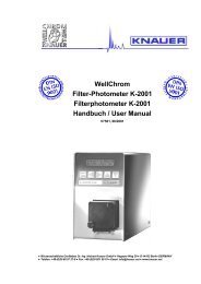
WellChrom Pneumatic-Pump K-1900 Pneumatische -Pumpe K-1900 ...
WellChrom Pneumatic-Pump K-1900 Pneumatische -Pumpe K-1900 ...
WellChrom Pneumatic-Pump K-1900 Pneumatische -Pumpe K-1900 ...

Sie wollen auch ein ePaper? Erhöhen Sie die Reichweite Ihrer Titel.
YUMPU macht aus Druck-PDFs automatisch weboptimierte ePaper, die Google liebt.
2ContentsInhaltGeneral Description 3Using this Manual 4Conventions in this Manual 4SOP’s in this manual 4Technical Data of <strong>Pneumatic</strong> <strong>Pump</strong> K–<strong>1900</strong> 5Setup of the <strong>Pneumatic</strong> <strong>Pump</strong> K–<strong>1900</strong> 5Unpacking 5Front View of the <strong>Pneumatic</strong> <strong>Pump</strong> K–<strong>1900</strong> 6Connecting the <strong>Pneumatic</strong> <strong>Pump</strong> K–<strong>1900</strong> 7Compressed Air Connections 7<strong>Pump</strong> Heads and Hydraulic Connections 7Identifying installed <strong>Pump</strong> Heads 7<strong>Pump</strong> Heads and Hydraulic Connections 8100, 250 and 500 ml Head 81000 ml Head 8Setting up the K-<strong>1900</strong> 9Piston Backflushing 9Air Pressure Influences 10Calibration for Constant Flow 11Easy Maintenance 12Changing and Cleaning the <strong>Pump</strong> Head 12Packing List 16Spare Parts and Accessories 17Warranty statement 33Declaration of conformity 34Allgemeine Beschreibung der <strong>Pneumatische</strong>n <strong>Pump</strong>e K–<strong>1900</strong> 18Hinweise zum Gebrauch des Handbuchs 19Konventionen in diesem Handbuch 19SOP's in diesem Handbuch 19Technische Daten der <strong>Pneumatische</strong>n <strong>Pump</strong>e K–<strong>1900</strong> 20Inbetriebnahme der <strong>Pneumatische</strong>n <strong>Pump</strong>e K-<strong>1900</strong> 20Auspacken 20Frontansicht der <strong>Pneumatische</strong>n <strong>Pump</strong>e K-<strong>1900</strong> 21Anschluss der <strong>Pneumatische</strong>n <strong>Pump</strong>e K–<strong>1900</strong> 22Druckluftanschluss 22<strong>Pump</strong>enköpfe und Lösungsmittelanschlüsse 22<strong>Pump</strong>enkopfidentifikation 22Flüssigkeitsverbindungen 23Betriebsvorbereitung 24Kolbenhinterspülung 24Pressluftdruck und Flüssigkeitsdruck und -fluss 25Kalibrierung für konstanten Fluss 26Wartung durch den Anwender 27Austausch und Reinigung des <strong>Pump</strong>enkopfes 27Lieferumfang 31Ersatzteile und Zubehör 32Gewährleistungsbedingungen 33Konformitätserklärung 34
General Description 3General DescriptionThe <strong>Pneumatic</strong> <strong>Pump</strong> K–<strong>1900</strong> has been developed for solvent delivery withinthe following fields:• Process chemistry• Column packing• Preparative chromatography.It is powered by pressurized air. It can deliver liquids with an adjustable flowrate. Since no electrical connection is required, the <strong>Pneumatic</strong> <strong>Pump</strong> K–<strong>1900</strong> issuitable for operation in explosion protected environments.The new <strong>Pneumatic</strong> <strong>Pump</strong> K-<strong>1900</strong> has been developed for constant pressureapplications. It is suitable for packing high performance col-umns (microbore,analytical and preparative ) up to 1000 bar. The flow is highly reproducible andonly little maintenance efforts are required.It features a double-piston design and can be configured with four differentpump heads to meet a broad range of require-ments in flow and pressureranges:100 ml pump head (0.1 – 99.9 ml/min), stainless steel, up to 1000 bar250 ml pump head (0.1 – 249.9 ml/min), stainless steel, up to 670 bar500 ml pump head (0.1 – 499.9 ml/min), stainless steel, up to 225 bar1000 ml pump head (0.1 – 999.9 ml/min), stainless steel, up to 160 barThe names of the pump heads have historical reasons. You can also operateany of the mentioned pump heads with our Preparative HPLC <strong>Pump</strong> K-1800. Inthe case of the <strong>Pneumatic</strong> <strong>Pump</strong> K–<strong>1900</strong> the piston strokes operate with ahigher frequency and therefore flow rates can be much higher than specified onthe pump head .The characterisics of flow and liquid pressure for the K-<strong>1900</strong> with the differentpump heads are listed in Table 2, „Technical data of individual pump heads“ onpage 5.<strong>Pump</strong> heads can be interchanged by loosening only four screws. Experiencedusers can disassemble the heads for simple maintenance tasks like cleaning,changing piston seals, etc.A cooling device (heat exchanger) to be mounted on the pump head isavailable. It allows to operate the <strong>Pneumatic</strong> <strong>Pump</strong> K–<strong>1900</strong> with supercriticalsolvents as CO 2 for Extraction and Supercritical Fluid Chromatography.The power unit of the pump consists of a pneumatic piston which is set inmotion by compressed air. The pneumatic power will be trans-mitted to thepiston rods by the power transmit lever.
4 Using this ManualUsing this ManualConventions in this ManualSpecial Warnings are indicated by the marginal warning sign and printed inbold letters.The marginal lamp symbol indicates helpful advice’s.Important Hints are marked by the marginal hand symbol.SOP’s in this manualThe Standard Operating Procedures (SOP) provided with this manual offer aconvenient way of structuring complex tasks in the operation of your <strong>WellChrom</strong><strong>Pneumatic</strong> <strong>Pump</strong> K–<strong>1900</strong>. They include step-by-step instructions leading theuser through all routine tasks during operation. They can be used fordocumentation purposes and be copied, applied signed, and filed in order todocument the performance of the instrument.Please operate the instrument and all accessories according toinstructions and SOP’s in this manual. This ensures proper results andlongevity of your equipment.Table 1SOP’s in this manualSOP 1 Preparing your K–<strong>1900</strong> for piston backflushing 9SOP 2 Start of Solvent Delivery 10SOP 3 Removing the <strong>Pump</strong> Head 12SOP 4 Removing and Checking Piston Rods 12SOP 5 Disassembling the <strong>Pump</strong> Head 13SOP 6 Assembling the <strong>Pump</strong> Head and Exchanging Piston Seals 14SOP 7 Installing the <strong>Pump</strong> Head 14SOP 8 Cleaning and Replacing Check Valves 15
Technical Data of <strong>Pneumatic</strong> <strong>Pump</strong> K–<strong>1900</strong> 5Technical Data of <strong>Pneumatic</strong> <strong>Pump</strong> K–<strong>1900</strong>Table 2Technical data of individual pump headsCharacteristics<strong>Pump</strong> Head100 ml 250 ml 500ml 1000 mlMaximum Flow Rate (ml/min) at300 500 1000 2000Minimum Back PressureMaximum Back Pressure (bar) for 1000 670 250 160Solvent DeliveryMaximum Allowed Air Pressure (bar) 4.2 *) 7 7 7Piston Stroke (mm) 9.5 9.5 9,5 9.5Stroke Volume per Cycle (ml) 0.6 1.35 3,05 5.4Diameter (mm) 6.35 9.525 14,29 19.05<strong>Pneumatic</strong> Transformation Ratio 1:250 1:96 1:47 1:23*) See warning below.With the 100 ml pump head the external air pressure must under nocircumstances never exceed 4.2 bar. Exceeding an external air pressureof 4.2 bar will lead to damage of pump head and pump mechanics. Thisdamage is not covered by guarantee.Setup of the <strong>Pneumatic</strong> <strong>Pump</strong> K–<strong>1900</strong>UnpackingUnpack the instrument and check pump and accessories for any damage due toshipping. Place any claims referring to damage at the transportation companyresponsible for shipping.Please use the packing list and make sure that the delivery of the <strong>Pneumatic</strong><strong>Pump</strong> K-<strong>1900</strong> is complete. If you have any questions regarding completedelivery, please call our service department as soon as possible.Please remove the protection foil from pump outlet.For the complete list of spare parts available please refer to chapter „SpareParts and Accessories“ on page 17.
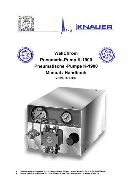
6 Setup of the <strong>Pneumatic</strong> <strong>Pump</strong> K–<strong>1900</strong>Front View of the <strong>Pneumatic</strong> <strong>Pump</strong> K–<strong>1900</strong>All operating elements and hydraulic connections are located on the front of thepump, see Fig. 1 and Fig. 2.342511 <strong>Pump</strong> head2 Flushing Valve3 Eluent pressure gauge4 Air pressure gauge5 Regulator for compressed airFig. 1 Front View of the <strong>Pneumatic</strong> <strong>Pump</strong> K–<strong>1900</strong>1.82.12.22.32.41.71.11.61.31.41.51.2Fig. 21 <strong>Pump</strong> Head 2 Flushing Valve1.1 Piston backflushing capillaries 2.1 Inlets to flushing valve1.2 Eluent inlets 2.2 De-aeration capillary 1/16“1.3 Head set screws 2.3 De-aeration screw1.4 Label with type of pump head 2.4 Eluent outlet to column1.5 Inlets valve housing1.6 Outlets valve housing1.7 Eluent outlets to flushing valve1.8 Connection capillaries<strong>Pump</strong> head and flushing valve
Connecting the <strong>Pneumatic</strong> <strong>Pump</strong> K–<strong>1900</strong> 7Connecting the <strong>Pneumatic</strong> <strong>Pump</strong> K–<strong>1900</strong>Compressed Air ConnectionsMake sure that your compressed air system to be used with the Pneu-matic<strong>Pump</strong> K–<strong>1900</strong> is able to maintain pressures up to 7 bar. With-out back pressurethe air consumption would be 80 L/min. If the <strong>Pneumatic</strong> <strong>Pump</strong> K-<strong>1900</strong> worksagainst pressure the consumption of air is much lower depending on the liquidpressure.The connector to the compressed air is located on the lower rear panel of thepump. Connect the coupler for the pressure tube to the coupler socket. Pushthe pressure tube (not delivered) from the com-pressed air supply over thecoupler and secure it with an appropriate clamp. Connect the coupler socket tothe compressed air connector of the pump (see Fig. 2).To disconnect from the compressed air supply: Hold the brass part of thecoupler with one hand and pull the blue part of the coupler socket away fromthe pump with the other hand.Compressedair supply<strong>Pump</strong>CouplerCouplersocketConnector forcompressed airFig. 3 Air pressure connection of the K-<strong>1900</strong><strong>Pump</strong> Heads and Hydraulic ConnectionsThe pump should be rinsed with a methanol-water mixture (1:9 v/v) beforefirst usage. Make sure that all hydraulic connec-tions are suitable for thesystem pressure and flow rate of your liquid transportation system.Identifying installed <strong>Pump</strong> HeadsMaximum flow rate, 100, 250, 500, or 1000 ml/min, is indicated on a label onthe front of the pump head. This values are valid for the HPLC-<strong>Pump</strong> K-1800.Working with the pneumatic pump K-<strong>1900</strong> the maximum flow rates areapproximately two times higher .Fig. 4<strong>Pump</strong> head label (1000ml head)
8 Connecting the <strong>Pneumatic</strong> <strong>Pump</strong> K–<strong>1900</strong><strong>Pump</strong> Heads and Hydraulic ConnectionsAll operating elements and hydraulic connections are located on the front of thepump, see Fig. 1 and Fig. 2.Make sure that all hydraulic connections are suited for the systempressure and flow rate of your HPLC System. During initial set-upprocedures, and also later when changing solvent, pay strict attention tothe miscibility of solvents to be used one after another, otherwise thefunction of the check valves may be adversely affected (see Fig. 14 on page15). By substitutions non-mis-cible solvents such as methanol and hexane,rinse after using methanol with an intermediate solvent that is misciblewith both solvents in all proportion, e.g. isopropanol.100, 250 and 500 ml HeadSolvent tubings are connected to the pump head according to Fig. 5. Make surethat the flat side of the ferrule is directed to the pump head and that the fittingscrew is fastened hand tight. According to the local conditions the tubings canbe connected either to the inlets valve housing (A) or to the eluent inlet (B).1 inlets valve housing2 eluent inlet3 ferrule4 fitting screwFig. 5A B100, 250 and 500 ml pump head: hydraulic connections1000 ml HeadPush the tubes directly over the connectors, and secure them by means ofappropriate clamps.Fig. 61000 ml pump head: hydraulic connections
Connecting the <strong>Pneumatic</strong> <strong>Pump</strong> K–<strong>1900</strong> 9Setting up the K-<strong>1900</strong>Never run the <strong>Pneumatic</strong> <strong>Pump</strong> K–<strong>1900</strong> without liquid in the pump head orin the piston backflushing compartment. For piston backflushing, followthe instructions below. Operation with-out liquid may lead to damage ofthe pump seals in short time.Piston BackflushingBackflushing the piston removes traces of salt and other decontaminants fromthe backside of the pistons.Especially if you use saline solvents or buffer solution we highly recommendthat you continuously backflush in order to prevent crystallization which candamage your piston seals.For best protection and error free long time operation of the pump head it isrecommended always to backflush the piston with an appropriate solvent(mostly water) according to the following SOP.SOP 1Preparing your K–<strong>1900</strong> for piston backflushingThis SOP applies to the <strong>Pneumatic</strong> <strong>Pump</strong> K–<strong>1900</strong>.1. Push a 1/16" ID tube over both piston backflushing capillaries.Fig. 7Piston backflushing capillaries2. Place one low end of the tubing in a flask.3. Fill the priming syringe with the backflushing liquid.4. Connect the syringe with the other tubing.5. Press liquid through the pump head, until it flows without any air bubblesinto the container.6. Remove tubings from capillary opening.If you want operation with continuous backflushing you can attach twocontainers of rinsing liquid instead of the priming syringe. The containers shouldbe positioned that one container is located higher than the other, thus ensuringliquid flow through the pump head without any assistance.When not backflushing continuously, we recommend to connect both capillaryopenings with a tubing to prevent vaporization of solvents and drying out of thepiston chamber.
10 Connecting the <strong>Pneumatic</strong> <strong>Pump</strong> K–<strong>1900</strong>SOP 2Start of Solvent DeliveryThis SOP applies to the <strong>Pneumatic</strong> <strong>Pump</strong> K–<strong>1900</strong>.1. Screw a blind fitting to the ”Eluent outlet to column”, Pos. {2.4} in Fig. 2and open the “De-aeration screw”, Pos. {2.3} for opening flushing valve.2. Connect the Luer-Lock syringe with the “De-aeration capillary”, Pos. {2.2}in Fig. 2 with the help of a short PTFE tube (ID 1,5 mm/ OD 2,1 mm). Thepump head needs to be filled with liquid by pulling eluent into the Luer-Lock syringe until liquid enters the syringe.3. Close the “De-aeration screw” and exchange the blind fitting with aregular 1/8” fittings to connect this outlet with an injection system, acolumn packing device, a chemical reactor or something else.4. Pull the Regulator for compressed air, see Fig. 2 for loosening up. Thepneumatic can be set in operation by turning the Regulator forcompressed air to the right (required air pressure increases). The eluentwill be transported to flushing valve.5. The pump should be stopped by turning the Regulator for compressed airto the left (required air pressure decreases towards 0 bar) and any unit(e.g. the column filling device) is connected to the solvent outlet.Air Pressure InfluencesThe resulting eluent pressure increases or decreases as a function ofcompressed air inlet pressure. Eluent pressure will nearly be constant, if thecompressed air inlet pressure remains constant. The Regulator for compressedair can be locked by pressing it to wards the instrument.The delivery volume depends on the required air pressure and the loss ofpressure along the column or any device that generates back pressure. Youcan reach the maximum delivery volume at minimum eluent pressure below 1bar and the maximum eluent pressure at the minimum flow rate. Fig. 8 up toFig. 10 show the delivery volume as a function of the eluent pressure for the100, 250 and 1000 ml pump head, respectively. In those figures you can seethe limit values for the liquid pressure and the flow rate corresponding to Table2, “Technical data of individual pump heads,” on page 5 and the maximumallowed air pressure for each pump head. By the constant required air pressurethe flow rate increases if the liquid pressure decreases. The Figures should helpto choose the pump head for your application.Liquid Pressure [bar]1200800400Required Compressed Air4,2 bar4bar3 bar2 bar1 bar100 ml00 100 200 300Flow Rate [ml/min]Fig. 8Interdependence of delivery volume and eluent pressure for the 100 ml pumphead
Connecting the <strong>Pneumatic</strong> <strong>Pump</strong> K–<strong>1900</strong> 11Liquid Pressure [bar]900600300Required Compressed Air7 bar6bar5 bar4 bar3 bar2 bar1 bar250 ml00 300 600 900Flow Rate [ml/min]Fig. 9Interdependence of delivery volume and eluent pressure for the 250 ml pumpheadLiquid Pressure [bar]21014070Required compressed air7 bar6 bar5 bar4 bar3 bar2 bar1000 ml1 bar00 800 1600 2400Flow Rate [ml/min]Fig. 10Interdependence of delivery volume and eluent pressure for the 1000 ml pumpheadCalibration for Constant FlowIf you want to use the pneumatic pump as a delivery pump with constantdelivery volume, you need to calibrate it.Fig. 11 shows typical calibration curves for two different columns with differentpressure losses along the column for the 250 ml pump head. In this figurecolumn 1 has a lower back pressure than column 2 at same flow rate, so it ispossible to obtain higher flow rates with the same required air pressure on thecolumn 1 compared to the column 2.For the calibration you have to measure the flow rate at different required airpressures from 1 up to 7 bar (up to 4.2 bar with the 100 ml pump head)120Flow Rate [ ml min -1 ]8040Column 1Column 201 2 3 4 5 6 7Fig. 11Typical calibration curves of the <strong>Pneumatic</strong> <strong>Pump</strong> K–<strong>1900</strong> for two differentcolumns (250 ml pump head)
12 Easy MaintenanceEasy MaintenanceChanging and Cleaning the <strong>Pump</strong> HeadSOP 3Removing the <strong>Pump</strong> HeadThis SOP refers to the <strong>Pneumatic</strong> <strong>Pump</strong> K–<strong>1900</strong>.For exchange of the pump head, or for disassembling it in order to clean valvesor replace piston seals, piston rods etc., the pump head can easily be removed.1. Clean the pump head with a suitable cleaning reagent and then withdistilled water according to chapter „Start of Solvent Delivery“ on page10, step 1 and 2.If organic solvents remain in the pump head, danger of skin irritation mayexist.2. Remove the two solvent tubings from the „Eluent inlets“, Pos. {1.2}seeFig. 2 on page 6.3. Loosen the two „Eluent outlets to transducer“, Pos. {1.7} and the two„Inlets to transducer“, Pos. {2.1}.4. Remove the two „Connection capillaries“, Pos. {1.8}, beginning with theupper „n“-shaped one.5. Loosen the „Inlets valve housing“, Pos. {1.5}as well as the fittings at„Outlets valve housing“, Pos. {1.6}.6. Using a hexagonal spanner no. 4 (4 mm), loosen just two diagonallyopposed „Head set screws“, Pos. {1.3}. Remove the screws.7. Carefully loosen the two remaining screws, alternating from one to theother, approx. half a turn. This prevents the pump head from tilting andbecoming damaged. Once the spring tension has been reduced, hold thepump head firmly in one hand while removing the screws completely withthe other hand.8. Carefully remove the pump head.SOP 4Removing and Checking Piston RodsThis SOP refers to the following pump heads:100 ml stainless steel, KNAUER order number A 4029250 ml stainless steel, KNAUER order number A 4021500 ml stainless steel, KNAUER order number A 40381000 ml stainless steel, KNAUER order number A 40221. Remove <strong>Pump</strong> head as described in SOP „Removing the <strong>Pump</strong> Head“.If you only wish to check the piston rods, you do not need to disassemblethe pump head any further.2. The „Piston rods“, Pos. {3.17} in Fig. 12 on page 13 may be removedusing pliers. Take the tip of the piston using the pliers, and pull it outcarefully in a straight line.If the rods are broken, you must check the entire pump head for damage.
Easy Maintenance 13SOP 5Disassembling the <strong>Pump</strong> HeadThis SOP refers to the pump heads 100 ml, 250 ml, 500 ml, and 1000 ml.3.13.33.63.103.13 3.143.113.193.183.163.153.173.113.123 B3.103 A3.53.2Fig. 123.A <strong>Pump</strong> head housing, front block 3.11 Piston seals3.B <strong>Pump</strong> head housing, basic plate 3.12 O-shaped sealings3.1 Piston backflushing3.13 Distance platescapillaries 1/16“ 3.14 Spacing bolts3.2 Eluent inlets 3.15 Springs3.3 <strong>Pump</strong> head set screws 3.16 Guides for springs3.5 Inlet valve housing 3.17 Piston rods3.6 Outlet valve housing 3.18 Retaining plate3.10 Check valves, inlet and outlet 3.19 Retaining plate screwsExplosion diagram of pump heads1. Apply SOP 4 "Removing and Checking Piston Rods".2. Loosen the two „Retaining plate screws“, Pos. {3.19} half a turn,alternating from one to the other to avoid damaging the „Retaining plate“.3. Because the two screws are very tight, it may be helpful to either clampthe pump head or to press one of its side surfaces against a table withone hand while loosening the screws.4. Unscrew the two screws strictly alternating due to strong force of the„Springs“, Pos. {3.15} behind the plate, and remove them.5. Remove the „Retaining plate“, Pos. {3.18}.6. You can now remove the „Guides for springs“, Pos. {3.16}, the „Springs“,Pos. {3.15} as well as the two „Distance plates“, Pos. {3.13}.7. Using the SW 10 spanner, loosen and remove the „Spacing bolts“, Pos.{3.14}. These bolts are seated very tightly. Follow the tip given in step 3.8. Lift and remove the „<strong>Pump</strong> head housing, basic plate“, Pos. {3.B}.9. To remove the piston seals, Pos. {3.11} in the basic plate {3.B} and in thefront block {3.A}, use an appropriate tool, e.g. a screw driver and carefullylever the four piston seals.
14 Easy MaintenanceSOP 6Assembling the <strong>Pump</strong> Head and Exchanging Piston SealsThis SOP refers to the pump heads 100 ml, 250 ml, 500 ml, and 1000 ml.All positions of components refer to Fig. 12 „Explosion Diagram and list of partsof 100 ml, 250 ml, and 1000 ml pump heads“ on page 13.1. It is recommended to exchange all four piston seals located in the pumpheads after disassembling the pump head.Fig. 13Open side of piston seal2. With the open side facing downwards, carefully press the „Piston seals“,Pos. {3.11} into the „<strong>Pump</strong> head housing, front block“, Pos. {3.A} and„<strong>Pump</strong> head housing, basic plate“, Pos. {3.B}, making sure to keep themstraight.3. Insert the O-ring sealings part {3.12}.4. Put the two housing parts together, positioning the O-ring side of part{3.B} against part {3.A}. Be sure that the backflushing capillaries arepositioned on the top side of the head - see label on front of part {3.A} fororientation.5. Insert the two „Spacing bolts“, Pos. {3.14}, screw them in with the handand tighten them as firmly as before using the SW 10 spanner.6. Put in the two „Distance plates“, Pos. {3.13}, position the „Springs“, Pos.{3.15} and the „Guides for springs“, Pos. {3.16}.7. Put the „Retaining plate“, Pos. {3.18} over the „Guides for springs“, Pos.{3.16}, with the conical bore of the plate directed outwards.8. Insert the two „Retaining plate screws“, Pos. {3.19}, press the plate downwith one hand and tighten the screws with a screw driver, strictlyalternating due to strong force of the „Springs“, Pos. {3.15}.9. Carefully insert the piston rods, see „Piston rods“, Pos. {3.17} withoutbending or quenching the rods.10. The „Retaining plate screws“, Pos. {3.19} must be tightened that they areseated as securely as before.SOP 7Installing the <strong>Pump</strong> HeadThis SOP refers to the following pump heads:100 ml stainless steel, KNAUER order number A 4029250 ml stainless steel, KNAUER order number A 4021500 ml stainless steel, KNAUER order number A 40381000 ml stainless steel, KNAUER order number A 40221. Make sure that the pump head is properly assembled.2. Position the head in a straight line onto the pump housing.3. Tighten all four „<strong>Pump</strong> head set screws“, Pos. {3.3} a few turns by hand.4. Alternating from one to the next, tighten two diagonally opposed screwshalf a turn at a time, until the pump head is correctly seated.5. Tighten the two other screws.6. Make sure that all four „<strong>Pump</strong> head set screws“, Pos. {3.3} are securelytightened.
Easy Maintenance 157. Install the two „Connection capillaries“, Pos. {3.8}, beginning with thelower „s“-shaped one, and firmly tighten all fittings.SOP 8Cleaning and Replacing Check ValvesThis SOP refers to the following pump heads:100 ml stainless steel, KNAUER order number A 4029250 ml stainless steel, KNAUER order number A 4021500 ml stainless steel, KNAUER order number A 40381000 ml stainless steel, KNAUER order number A 4022If the check valves become dirty they will no longer open and close correctly.You can remove the check valves for cleaning from the pump head afterloosening and removing the „Inlet valve housing“, Pos. {3.5} and „Outlet valvehousing“, Pos. {3.6}, and then disassemble them according to the followinginstructions.1. Place the valves in a suitable cleaning solution. Use a ultrasonic bath toclean the valve. If malfunction persists, use steps 2…5 of this SOP.2. Using a knife or similar, carefully remove the valve seal from the housing,see Fig. 23 on page 41.3. Remove the valve ball out of the housing.4. Clean the individual parts. We recommend a ultrasonic bath.5. Assemble the check valves in reverse order, use Figure Fig. 14.HousingValve sealValve ballFig. 14Components of the check valves of all pump heads available
16 Packing ListPacking ListTable 3The delivery of the <strong>Pneumatic</strong> HPLC <strong>Pump</strong> K-<strong>1900</strong> with the 100 ml, 250 ml, 500ml, or 1000 ml pump head (order number A 40281, A 40282, A 40285, A 40289)comprising the items according to Table 3.The delivery consists of:Peaces Description<strong>Pump</strong> basic unit:1 User manual1 Coupler, to attach air pressure tube1 Coupler socket1 Blind fittingSet of tools including:1 Double open-end wrench, 13 and 17 mm1 Double open-end wrench, 8 and 10 mm1 Double open-end wrench, 1/4” and 5/16”1 Screw key, 4 mm1 Recessed head screw No. 2Syringe set including1 Syringe1 Luer-Lock needle1 0,1 m PTFE tube (ID 1,5 mm/ OD 2,1 mm)Eluent outlet set including1 Capillary AD 1/8”2 Fitting screws2 FerrulesSet of fittings and adapters (1/8” – 1/16”) including1 1/8” – 1/16” transforming coupler1 Fitting screw for capillary AD 1/8” (M8x1)1 Ferrule for capillary AD 1/8”1 Fitting screw for capillary AD 1/16”1 Ferrule for capillary AD 1/16”<strong>Pump</strong> head 100 ml, order number A 4029 *)1 <strong>Pump</strong> head 100 ml4 Tube fitting screws6 Tube ferrules2 1 m PTFE tube (ID 3 mm/ OD 4 mm)1 0,5 m PTFE tube (ID 1,5 mm/ OD 2,1 mm)<strong>Pump</strong> head 250 ml, order number A 4021 *)1 <strong>Pump</strong> head 250 ml4 Tube fitting screws6 Tube ferrules2 1 m PTFE tube (ID 3 mm/ OD 4 mm)1 0,5 m PTFE tube (ID 1,5 mm/ OD 2,1 mm)<strong>Pump</strong> head 500 ml, order number A 4038 *)1 <strong>Pump</strong> head 500 ml4 Tube fitting screws6 Tube ferrules2 1 m PTFE tube (ID 3 mm/ OD 4 mm)1 0,5 m PTFE tube (ID 1,5 mm/ OD 2,1 mm)<strong>Pump</strong> head 1000 ml, order number A 4022 *)1 <strong>Pump</strong> head 1000 ml2 1 m PTFE tube (ID 7 mm/ OD 9 mm)1 0,5 m PTFE tube (ID 1,5 mm/ OD 2,1 mm)*) Please select the appropriate pump head for your special requirements.
Spare Parts and Accessories 17Spare Parts and AccessoriesTable 4KNAUEROrder NumberUser Manual V 7027Optional <strong>Pump</strong> Heads<strong>Pump</strong> Head 100 ml incl. accessory kit A 4029<strong>Pump</strong> Head 250 ml incl. accessory kit A 4021<strong>Pump</strong> Head 500 ml incl. accessory kit A 4025<strong>Pump</strong> Head 1000 ml incl. accessory kit A 4022Spare Parts for <strong>Pump</strong> Head 100 mlsee Explosion Diagram of <strong>Pump</strong> Heads on page 13Check valve {3.10} A 1122Piston rod 1/4´´ {3.17} A 0747Set of Piston seals including2 piston seals for 1/4´´ pistons{3.11}1 O-shaped sealing {3.12} A 0746Set of Hydraulic connections including10 tube fitting screws and 10 tube ferrules A 2003Inlet junction including2 Inlet valve housings1 T peace, fitting srcew with ferrule1 left-hand and 1 right-hand connection tube A 1121Spare Parts for <strong>Pump</strong> Head 250 mlCheck valve {3.10} A 1122Piston rod 3/8´´ {3.17} A 1017Set of Piston seals including2 piston seals for 3/8´´ pistons{3.11}1 O-shaped sealing {3.12} A 1046Set of Hydraulic connections including10 tube fitting screws and 10 tube ferrules A 2003Inlet junction including2 Inlet valve housings1 T peace, fitting srcew with ferrule1 left-hand and 1 right-hand connection tube A 1117Spare Parts for <strong>Pump</strong> Head 500 mlCheck valve {3.10} A 1080Piston rod 9/16´´ {3.17} A 1478Set of Piston seals including2 piston seals for 9/16´´ pistons{3.11}1 O-shaped sealing {3.12} A 1479Spare Parts for <strong>Pump</strong> Head 1000 mlCheck valve {3.10} A 1080Piston rod 3/4´´ {3.17} A 1015Set of Piston seals including2 piston seals for 3/4´´ pistons{3.11}1 O-shaped sealing {3.12} A 1077
18 Allgemeine Beschreibung der <strong>Pneumatische</strong>n <strong>Pump</strong>e K–<strong>1900</strong>Allgemeine Beschreibung der <strong>Pneumatische</strong>n <strong>Pump</strong>e K–<strong>1900</strong>Die neue <strong>Pneumatische</strong> <strong>Pump</strong>e K–<strong>1900</strong> wurde für die Lösungsmittelförderungin folgenden Einsatzgebieten entwickelt:• Chemische Prozesse• Säulenfüllung• Präparative ChromatographieSie wird mit Druckluft angetrieben. Die Lösungsmittelförderung erfolgt miteinstellbarem Förderdruck. Da keine elektrischen Anschlüsse notwendig sind,kann sie auch in explosionsgeschützter Umgebung betrieben werden.Die neue <strong>Pneumatische</strong> <strong>Pump</strong>e K–<strong>1900</strong> wurde für Anwendungen beikonstantem Druck entwickelt. Sie ist zum Füllen von Hochleistungssäulen(microbore, analytisch und präparativ) bis zu 1000 bar geeignet. Der Fluss istausgezeichnet reproduzierbar, und es ist nur geringster Wartungsaufwanderforderlich.Die <strong>Pump</strong>e zeichnet sich durch ein Doppelkolbensystem aus. Sie kann mit vierverschiedenen <strong>Pump</strong>enköpfen konfiguriert werden und deckt dadurch einenweiten Fluss- und Druckbereich ab:• 100 ml-<strong>Pump</strong>enkopf, Edelstahl, bis zu 1000 bar• 250 ml-<strong>Pump</strong>enkopf, Edelstahl, bis zu 670 bar• 500 ml-<strong>Pump</strong>enkopf, Edelstahl, bis zu 225 bar• 1000 ml-<strong>Pump</strong>enkopf, Edelstahl, bis zu 160 barDie Bezeichnung der <strong>Pump</strong>enköpfe hat historische Ursachen. Sie können diegenannten <strong>Pump</strong>enköpfe auch mit unserer Präparativen HPLC <strong>Pump</strong>e K-1800verwenden. Beim Betrieb mit der pneumatischen <strong>Pump</strong>e K–<strong>1900</strong> arbeiten dieKolbenantriebe mit einer höheren Frequenz und deshalb kann ein wesentlichhöherer Fluss realisiert werden, als er auf den <strong>Pump</strong>enköpfen angegeben ist.Die Zusammenhänge von Fluss und hydraulischem Druck sind für dieverschiedenen <strong>Pump</strong>enköpfe der K-<strong>1900</strong> in Tabelle 2, Technische Daten dereinzelnen <strong>Pump</strong>enköpfe auf Seite 5 aufgelistet.Die <strong>Pump</strong>enköpfe können durch Lösen von nur vier Schrauben ausgetauschtwerden. Erfahrene Anwender können die Köpfe zu Reinigungszwecken oderzum Austausch von Verschleißteilen einfachzerlegen.Darüber hinaus steht eine am <strong>Pump</strong>enkopf zu montierende Kühlvorrichtung(Wärmeaustauscher) zur Verfügung. Sie ermöglicht den Betrieb der<strong>Pneumatische</strong>n <strong>Pump</strong>e K–<strong>1900</strong> mit superkritischen Flüssigkeiten, wie CO2, fürExtraktionen und für die Superkritische Flüssigchromatographie.Die Antriebseinheit der <strong>Pump</strong>e besteht aus einem pneumatischen Kolben, derdurch Druckluft angetrieben wird. Die pneumatische Energie wird durchKraftübertragungshebel auf die Kolbenstangen die übertragen.
Hinweise zum Gebrauch des Handbuchs 19Hinweise zum Gebrauch des HandbuchsKonventionen in diesem HandbuchBesondere Warnhinweise und Hinweise auf mögliche Probleme sind mit demWarnsymbol gekennzeichnet.Ein nützlicher Tip wird in der Marginalspalte durch das Symbolhervorgehoben.Wichtige Hinweise werden in der Marginalspalte durch das Hinweissymbolkenntlich gemacht.Die Bezüge zu Details in Abbildungen im Text dieses Handbuchs werden durchdas Format wie z.B.: siehe Pos. {3} in Abb. 1 auf Seite 6 charakterisiert.SOP's in diesem HandbuchDie Standardarbeitsanweisungen (Standard Operating Procedures, SOP)dieses Handbuches ermöglichen die Strukturierung zusammenhängenderAufgaben beim Betrieb Ihrer <strong>Pneumatische</strong>n <strong>Pump</strong>e K-<strong>1900</strong>. Sie beinhaltenschrittweise Anweisungen, die den Anwender durch alle Aufgaben führen. Siekönnen gleichfalls zu Dokumentationszwecken genutzt werden. Sie könnenkopiert, angewendet, unterzeichnet und abgelegt werden, um so dieLeistungsfähigkeit Ihres Gerätes zu dokumentieren.Bitte betreiben Sie das Gerät inklusive Zubehör gemäß der SOPs indiesem Handbuch. Andernfalls können fehlerhafte Meßergebnisse,Beschädigungen oder gesundheitliche Beeinträchtigungen desAnwenders eintreten, obwohl dieses Gerät außerordentlich robust undbetriebssicher ist.Tabelle 1SOP’s in diesem HandbuchSOP 1 Einrichtung der <strong>Pneumatische</strong> <strong>Pump</strong>e K-<strong>1900</strong> für die Kolbenhinterspülung 24SOP 2 Starten der Lösungsmittelförderung 25SOP 3 <strong>Pump</strong>enkopf ausbauen 27SOP 4 Kolbenstangen ausbauen und prüfen 27SOP 5 <strong>Pump</strong>enkopf zerlegen 28SOP 6 Zusammenbau des <strong>Pump</strong>enkopfes und Austausch der Kolbendichtungen 29SOP 7 <strong>Pump</strong>enkopf einbauen 29SOP 8 Kugelventile reinigen und ersetzen 30
20 Technische Daten der <strong>Pneumatische</strong>n <strong>Pump</strong>e K–<strong>1900</strong>Technische Daten der <strong>Pneumatische</strong>n <strong>Pump</strong>e K–<strong>1900</strong>Tabelle 2Technische Daten der einzelnen <strong>Pump</strong>enköpfeMerkmal<strong>Pump</strong>enkopf100 ml 250 ml 500ml 1000 mlMaximale Flussrate (ml/min) bei 300 500 1000 2000minimalem GegendruckLösungsmittelförderung bei maximalzulässigem Pressluftdruck (bar)10004,2 *) 670725071607Kolbenhub (mm) 9,5 9,5 9,5 9,5Hubvolumen je Zyklus (ml) 0,6 1,35 3,05 5,4Kolbendurchmesser (mm) 6,35 9,525 14,29 19,05<strong>Pneumatische</strong>s Umwandlungsverhältnis 1:250 1:96 1:47 1:23*) Siehe Warnung unten.Beim 100 ml-<strong>Pump</strong>enkopf darf der Pressluftdruck den Wert von 4,2 bar aufkeinen Fall übersteigen. Ein höherer Druck als 4,2 bar führt zurBeschädigung des <strong>Pump</strong>enkopfes und der <strong>Pump</strong>enmechanik. DieseSchäden fallen nicht unter die Garantiegewährleistung.Inbetriebnahme der <strong>Pneumatische</strong>n <strong>Pump</strong>e K-<strong>1900</strong>AuspackenAlle KNAUER-Geräte werden ab Werk sorgfältig und sicher für den Transportverpackt. Prüfen Sie dennoch nach dem Auspacken alle Geräteteile und dasZubehör auf mögliche Transportschäden und machen Sie gegebenenfallsSchadensersatzansprüche sofort beim Transportunternehmen geltend.Bitte überprüfen Sie gemäß Abschnitt Lieferumfang auf Seite 31 das Zubehörauf Vollständigkeit. Sollte trotz unserer sorgfältigen Ausgangskontrollen ein Teilfehlen, wenden Sie sich bitte an unsere Serviceabteilung.Bitte entfernen Sie die transparente Schutzfolie vom <strong>Pump</strong>enausgang.Die komplette Liste der verfügbaren Verschleiß- und Ersatzteile finden Sie imAbschnitt Ersatzteile und Zubehör auf Seite 32.
Inbetriebnahme der <strong>Pneumatische</strong>n <strong>Pump</strong>e K-<strong>1900</strong> 21Frontansicht der <strong>Pneumatische</strong>n <strong>Pump</strong>e K-<strong>1900</strong>Alle Bedienelemente und hydraulischen Anschlüsse befinden sich an derFrontseite der <strong>Pump</strong>e, siehe Abb. 134251Abb. 11 <strong>Pump</strong>enkopf2 Druckaufnehmer3 Manometer, Flüssigkeit4 Manometer, Pressluft5 DruckluftreglerFrontansicht mit <strong>Pump</strong>enkopf und Druckaufnehmer1.82.12.22.32.41.71.11.61.31.41.51.2Abb. 21 <strong>Pump</strong>enkopf 2 Druckaufnehmer1.1 Kolbenhinterspülungskapillare 2.1 Flüssigkeitseinlass1.2 Flüssigkeitseinlässe 2.2 Entlüftungskapillare 1/16“1.3 Befestigungsschrauben 2.3 Entlüftungsschraube1.4 Label mit <strong>Pump</strong>enkopftyp 2.4 Flüssigkeitsauslass zum System1.5 Einlassventilgehäuse1.6 Auslassventilgehäuse1.7 Flüssigkeitsauslass zum Druckaufnehmer1.8 Verbindungskapillaren<strong>Pump</strong>enkopf und Druckaufnehmer
22 Inbetriebnahme der <strong>Pneumatische</strong>n <strong>Pump</strong>e K-<strong>1900</strong>Anschluss der <strong>Pneumatische</strong>n <strong>Pump</strong>e K–<strong>1900</strong>DruckluftanschlussStellen Sie sicher, dass die für den Betrieb der <strong>Pneumatische</strong>n <strong>Pump</strong>e K–<strong>1900</strong>verwendete Pressluftquelle einen Druck von bis zu 7 bar zur Verfügung stellt.Ohne Gegendruck liegt der Luftverbrauch bei etwa 80 l/min. Sobald die<strong>Pneumatische</strong> <strong>Pump</strong>e K–<strong>1900</strong> gegen einenFlüssigkeitsdruck arbeitet, ist inAbhängigkeit von diesem der Verbrauch deutlich geringer.Der Druckluftanschluss der <strong>Pump</strong>e befindet sich im unteren Bereich derGeräterückseite. Verschrauben Sie die Schlaucholive mit der Druckkupplungund schieben Sie den Druckschlauch (nicht im Lieferumfang) auf die Olive.Sichern Sie den Schlauch mit einer passenden Schelle. Schieben Sie dieDruckkupplung auf den Druckluft-anschluss der <strong>Pump</strong>e, siehe Abb. 3.Zum Trennen von der Druckluftquelle halten Sie die Schlaucholive derDruckkupplung mit einer Hand fest, während Sie den blauen Ring mit deranderen Hand von der <strong>Pump</strong>e weg ziehen.DruckkupplungSchlauchschelleDruckluftanschluss<strong>Pump</strong>eDruckluftleitungSchlaucholiveAbb. 3 Druckluftanschluss der K-<strong>1900</strong><strong>Pump</strong>enköpfe und LösungsmittelanschlüsseVor dem ersten Einsatz der <strong>Pump</strong>e sollte diese mit einer Methanol-WasserMischung (1:9 v/v) gespült werden. Vergewissern Sie sich, dass alleSchlauchverbindungen für den erforderlichen Systemdruck und dieFlussrate geeignet sind.<strong>Pump</strong>enkopfidentifikationDie <strong>Pump</strong>enköpfe können anhand der auf der Frontseite befindlichen Labelsidentifiziert werden. Die aufgedruckten Flussraten von 100 ml/min, 250 ml/min,500 ml/min beziehungsweise 1000 ml/min sind die Maximalwerte dieser<strong>Pump</strong>enköpfe bei ihrem Einsatz mit der HPLC-<strong>Pump</strong>e K-1800. Die mit der<strong>Pneumatische</strong>n <strong>Pump</strong>e K-<strong>1900</strong> erreichbaren maximalen Flüsse sind (alsFaustregel) um den Faktor zwei größer.Abb. 4<strong>Pump</strong>enkopflabel (1000ml Kopf)
Inbetriebnahme der <strong>Pneumatische</strong>n <strong>Pump</strong>e K-<strong>1900</strong> 23FlüssigkeitsverbindungenAlle Flüssigkeitsanschlüsse befinden sich auf der Vorderseite der<strong>Pneumatische</strong> <strong>Pump</strong>e K-<strong>1900</strong>, siehe Abb. 1 auf Seite 21.Bitte achten Sie sowohl beim ersten Setup der <strong>Pump</strong>e, als auch bei jedemspäteren Lösungsmittelwechsel strikt auf die Mischbarkeit der nacheinanderverwendeten Lösungsmittel, da sonst die Funktion der Kugelventilenachteilig beeinflusst werden kann, siehe Abb. 14 auf Seite 30.Beim Wechsel zwischen nicht mischbaren Flüssigkeiten führen Sie bitteeine Zwischenspülung mit einem Lösungsmittel durch, dass mit beidenanderen Lösungsmitteln unbegrenzt mischbar ist. In den meisten Fällenist i-Propanol geeignet.100, 250 und 500 ml KopfDie Lösungsmittelschläuche werden entsprechend Abb. 5 mit dem <strong>Pump</strong>enkopfverbunden. Je nach den konkreten örtlichen Bedingungen können dieSchläuche direkt mit der Einlassventiverschraubung (A) verbunden werdenoder mit dem Eluenteneinlass (B). Stellen Sie sicher, dass die flache Seite desSchneidrings zum <strong>Pump</strong>enkopf zeigt und dass die Befestigungsschraubehandfest angezogen wird.1 Einlassventilverschraubung2 Eluenteneinlass3 Schneidring4 BefestigungsschraubeA BAbb. 5<strong>Pump</strong>enkopf: Anschluss von Lösungsmitteln 100, 250 und 500 ml Kopf1000 ml KopfSchieben Sie die Schläuche direkt auf die Schlaucholiven und sichern Sie siemit geeigneten Schlauchschellen.Abb. 6<strong>Pump</strong>enkopf: Anschluss von Lösungsmitteln 1000 ml Kopf
24 Inbetriebnahme der <strong>Pneumatische</strong>n <strong>Pump</strong>e K-<strong>1900</strong>BetriebsvorbereitungLassen Sie die <strong>Pneumatische</strong> <strong>Pump</strong>e K–<strong>1900</strong> niemals ohne Flüssigkeit im<strong>Pump</strong>enkopf oder im Kolbenhinterspülungsbereich laufen. ZurKolbenhinterspülung verfahren Sie bitte gemäß den nachfolgendenInstruktionen. Der Betrieb ohne Flüssigkeit kann schnell zur Zerstörungder Dichtungen in der <strong>Pump</strong>e führen.KolbenhinterspülungDie Kolbenhinterspülung entfernt Spuren von Salz oder anderer Stoffe aus demBereich hinter den Kolbendichtungen.Wenn Sie mit Salzlösungen oder Pufferlösungen arbeiten, empfehlen wirdringend, die Kolben kontinuierlich zu hinterspülen, damit es durchAuskristallisierung nicht zu Beschädigungen der Kolbendichtungen kommt.Für den besten Schutz und langes fehlerfreies Arbeiten des <strong>Pump</strong>enkopfesempfehlen wir in jedem Fall, den Kolben mit einem geeigneten Lösungsmittel(meistens Wasser) gemäß der folgenden SOP zu hinterspülen.SOP 1Einrichtung der <strong>Pneumatische</strong> <strong>Pump</strong>e K-<strong>1900</strong> für dieKolbenhinterspülungDiese SOP gilt für die <strong>Pneumatische</strong> <strong>Pump</strong>e K-<strong>1900</strong>.1. Schieben Sie zwei Schlauchstücke mit einem Innendurchmesser von1/16“ über die Anschlüsse für die Kolbenhinterspülung.Abb. 7Kapillaranschlüsse für die Kolbenhinterspülung2. Legen Sie ein Schlauchende in ein Auffanggefäß.3. Füllen Sie die Glasspritze (im Zubehör enthalten) mit einer geeignetenSpülflüssigkeit (vorzugsweise Wasser).4. Verbinden Sie die Spritze mit dem zweiten Schlauchende.5. Drücken Sie die Spülflüssigkeit durch den <strong>Pump</strong>enkopf, bis sie ohneLuftblasen in das Auffanggefäß läuft.6. Entfernen Sie die Schlauchstücke wieder von den Spülanschlüssen.Zur kontinuierlichen Kolbenhinterspülung können Sie statt der Glasspritze aucheinen Behälter mit Spülflüssigkeit anschließen. Dieser sollte etwas höher alsdas Auffanggefäß gestellt werden, so dass die Spülflüssigkeit ohne weitereUnterstützung durch den <strong>Pump</strong>enkopf laufen kann.Wir empfehlen weiterhin, beide Spülöffnungen des <strong>Pump</strong>enkopfs nach demSpülen mit einem Schlauchstück zu verbinden, um das Verdampfen vonLösungsmittel und damit das Austrocknen der Kolbenkammer zu vermeiden.
Inbetriebnahme der <strong>Pneumatische</strong>n <strong>Pump</strong>e K-<strong>1900</strong> 25SOP 2Starten der Lösungsmittelförderung1. Schrauben Sie den Verschlussstopfen auf den Flüssigkeitsauslass zumSystem , Pos. {2.4} in Abb. 2 und öffnen Sie die Belüftungsschraube,Pos. {2.3}.2. Verbinden Sie die Luer-Lock Spritze mittels eines kurzen PTFE-Schlauchstückes (ID 1,5 mm/ OD 2,1 mm) mit der Entlüftungskapillare”,Pos. {2.2} in Abb. 2. Der <strong>Pump</strong>enkopf wird gefüllt, indem dasLösungsmittel in die Spritze angesaugt wird, bis es dort zu sehen ist.3. Schließen Sie die Entlüftungsschraube und tauschen Sie denVerschlussstopfen gegen ein normales 1/8” Fitting zur Verbindung miteinem Injektionssystem, einer Säulenfüllvorrichtung, einem chemischenReaktor oder sonstigen Geräten aus.4. Ziehen Sie den Regulierungsknopf für die Pressluft, siehe Abb. 2 aufSeite 9, aus der Rasterung heraus. Die Pneumatik wird in Betriebgesetzt, indem Sie den Regulator im Uhrzeigersinn drehen um dieDruckluftzufuhr zu erhöhen. Der Eluent wird in Richtung zumDruckaufnehmer gefördert.5. Die <strong>Pump</strong>e wird gestoppt, indem Sie durch Linksdrehung derPressluftregulierung den Druck gegen 0 führen.Pressluftdruck und Flüssigkeitsdruck und -flussDer resultierende Flüssigkeitsdruck erhöht sich oder sinkt in Abhängigkeit vomEingangsdruck der Pressluft. Wird der Pressluftdruck konstant gehalten,verbleibt der Flüssigkeitsdruck ebenfalls praktisch konstant. DiePressluftdruckregulierung kann dadurch konstant gehalten werden, dass derRegulatorknopf bis zum Einrasten gegen das Gehäuse der <strong>Pump</strong>e gedrücktwird.Das geförderte Volumen hängt von dem vorliegenden Pressluftdruck, wie auchvon dem durch eine Säule oder einen sonstigen Widerstand erzeugtenGegendruck ab. Das maximale Fördervolumen wird bei minimalemFlüssigkeitsdruck, < 1 bar, und der maximale Flüssigkeitsdruck bei minimalerFlussrate erreicht. Die Abb. 8 bis Abb. 10 zeigen das Fördervolumen alsFunktion des Flüssigkeitsdruckes für die 100 ml-, 250 ml- und 1000 ml-<strong>Pump</strong>enköpfe.In den Abbildungen sind für jeden der <strong>Pump</strong>enköpfe entsprechend auch derTabelle 2, Technische Daten der einzelnen <strong>Pump</strong>enköpfe, auf Seite 5 dieGrenzwerte für den Flüssigkeitsdruck und die maximal zulässigenPressluftdrücke ersichtlich. Bei konstant anliegendem Pressluftdruck steigt dieFlussrate, wenn der Flüssigkeitsgegendruck sinkt. Die Abbildungen sollen Ihnenbei der Auswahl des für Ihre Anforderungen geeigneten <strong>Pump</strong>enkopfes helfen.Gegendruck [bar]1200800400Erforderliche Druckluft4,2 bar4bar3 bar2 bar1 bar100 ml00 100 200 300Flussrate [ml/min]Abb. 8Abhängigkeit des Fördervolumens vom Flüssigkeitsdruck für den 100 ml-<strong>Pump</strong>enkopf
26 Inbetriebnahme der <strong>Pneumatische</strong>n <strong>Pump</strong>e K-<strong>1900</strong>Gegendruck [bar]900600300Erforderliche Druckluft7 bar6 bar5 bar4 bar3 bar2 bar1 bar250 ml00 300 600 900Flussrate [ml/min]Abb. 9Abhängigkeit des Fördervolumens vom Flüssigkeitsdruck für den 250 ml-<strong>Pump</strong>enkopfFörderdruck [bar]21014070Erforderliche Druckluft7 bar6 bar5 bar4 bar3 bar2 bar1000 ml1 bar00 800 1600 2400Flussrate [ml/min]Abb. 10Abhängigkeit des Fördervolumens vom Flüssigkeitsdruck für den 1000 ml-<strong>Pump</strong>enkopfKalibrierung für konstanten FlussUm die pneumatische <strong>Pump</strong>e für die Förderung eines konstanten Volumenseinzusetzen, muss sie kalibriert werden.Die Kalibrierungskurven haben für verschiedene Säulen und verschiedene<strong>Pump</strong>enköpfe unterschiedliche typische Verläufe. Bei gleichem Pressluftdrucksind mit Säulen, die einen geringeren Gegendruck aufbauen, höhere Flussratenerreichbar.Zur Kalibrierung müssen Sie den Fluss bei verschiedenen Pressluftdrücken von1 bis 7 bar (bis 4,2 bar für den 100 ml-<strong>Pump</strong>enkopf) messen.120Flussrate [ ml min -1 ]8040Säule 1Säule 201 2 3 4 5 6 7Abb. 11Typische Kalibrierkurven der pneumatischen <strong>Pump</strong>e K-<strong>1900</strong> für zweiunterschiedliche Säulen (250 ml-Kopf)
Wartung durch den Anwender 27Wartung durch den AnwenderAustausch und Reinigung des <strong>Pump</strong>enkopfesSOP 3<strong>Pump</strong>enkopf ausbauenDiese SOP gilt für die <strong>Pneumatische</strong> <strong>Pump</strong>e K-<strong>1900</strong>.Zum Wechsel des <strong>Pump</strong>enkopfes, zum Demontieren zwecks Reinigung oderAustauschs von Kolbenstangen oder -dichtungen kann dieser einfach vom<strong>Pump</strong>engehäuse abgenommen werden:1. Spülen Sie den <strong>Pump</strong>enkopf mit geeigneter Spülflüssigkeit und danachmit destilliertem Wasser.Organische Lösungsmittel aus dem <strong>Pump</strong>enkopf können zu einerBeeinträchtigung Ihrer Gesundheit führen.2. Lösen Sie die beiden Schläuche von den Einlassventilverschraubungen(100ml-Kopf Abb. 5 A), den Eluenteneinlässen (250ml- und 500ml-KopfAbb. 5 B) bzw. den Schlaucholiven (1000ml-Kopf Abb. 6).3. Lösen Sie die beiden Flüssigkeitsauslässe zum Druckaufnehmer, Pos.{1.7} und die beiden Einlässe am Druckaufnehmer, Pos. {2.1}, Abb. 1.4. Entfernen Sie die beiden Verbindungskapillaren, Pos. {1.8}, beginnendmit der oberen n-förmigen Kapillare.5. Lösen Sie die Einlässe, Pos. {1.5} und die BefestigungsschraubenAuslässe, Pos. {1.6}.6. Lösen Sie mit einem 4 mm Imbusschlüssel zwei diagonal gegenüberliegendeSchrauben der Pos. {1.3} und entfernen Sie diese.7. Lösen Sie die beiden verbleibenden Schrauben vorsichtig alternierenddurch halbe Drehungen. Dadurch vermeiden Sie mögliche Beschädigungendes <strong>Pump</strong>enkopfes. Sobald die Federn nicht mehr unterSpannung stehen, halten Sie den <strong>Pump</strong>enkopf mit einer Hand in derPosition und entfernen mit der anderen Hand die Schrauben.8. Nehmen Sie den <strong>Pump</strong>enkopf vorsichtig vom Gerät ab.SOP 4Kolbenstangen ausbauen und prüfenDiese SOP gilt für folgende <strong>Pump</strong>enköpfe:100 ml Edelstahl, KNAUER Bestellnummer A 4029250 ml Edelstahl, KNAUER Bestellnummer A 4021500 ml Edelstahl, KNAUER Bestellnummer A 40381000 ml Edelstahl, KNAUER Bestellnummer A 40221. Nehmen Sie den <strong>Pump</strong>enkopf gemäß SOP 3 <strong>Pump</strong>enkopf ausbauen ab.Um lediglich die Kolbenstangen zu prüfen, brauchen Sie den Kopf nichtweiter zu zerlegen.2. Die Kolbenstangen, Pos. {3.17} in Abb. 12 auf Seite 28, können mit einerZange herausgezogen werden. Fassen Sie die Spitze der Kolben miteiner geeigneten Zange und ziehen Sie sie vorsichtig, ohne zu verkanten,nach hinten heraus.Falls eine Kolbenstange gebrochen ist, sollten Sie den gesamten<strong>Pump</strong>enkopf auf Schäden untersuchen.
28 Wartung durch den AnwenderSOP 5<strong>Pump</strong>enkopf zerlegenDiese SOP gilt für die 100 ml, 250 ml, 500 ml und 1000 ml <strong>Pump</strong>enköpfe.3.13.33.63.103.13 3.143.113.193.183.163.153.173.113.123 B3.103 A3.53.23.A <strong>Pump</strong>enkopf, Frontblock 3.11 Kolbendichtungen3.B <strong>Pump</strong>enkopf, Basisplatte 3.12 O-Ringe3.1 Kolbenhinterspülungskapillare3.13 Druckscheiben1/16“ 3.14 Abstandsbolzen3.2 Lösungsmitteleinlass 3.15 Druckfedern3.3 Montageschrauben 3.16 Federführung3.5 Einlassventilhaltung 3.17 Kolbenstangen3.6 Auslassventilhaltung 3.18 Grundplatte3.10 Kugelventile(Ein- und Auslass)3.19 Schrauben der GrundplatteAbb. 12Explosionsdarstellung eines <strong>Pump</strong>enkopfes1. Wenden Sie die SOP 4 Kolbenstangen ausbauen und prüfen an.2. Lösen Sie die beiden Schrauben der Grundplatte, Pos. {3.19} vom<strong>Pump</strong>enkopf. Um Beschädigungen der Grundplatte zu vermeiden lösenSie die Schrauben alternierend um halbe Drehungen.3. Da diese Schrauben sehr fest sitzen, ist es ratsam, den <strong>Pump</strong>enkopfeinzuspannen oder eine der Seitenflächen auf eine feste Unterlage zupressen, während mit der anderen Hand die Schrauben gelockertwerden.4. Entfernen Sie die Grundplatte, Pos. {3.18}.5. Jetzt können Sie die Kupplungsbuchsen, Pos. {3.16}, die Druckfedern,Pos. {3.15}, wie auch die beiden Druckscheiben, Pos. {3.13} entfernen.6. Lösen Sie mit einem SW 10 Schlüssel die Abstandsbolzen, Pos. {3.14}.Da diese Schrauben ebenfalls sehr fest sitzen, folgen Sie dem in Schritt 3gegebenen Hinweis.7. Entfernen Sie die <strong>Pump</strong>enkopf, Basisplatte, Pos. {3.B}.
Wartung durch den Anwender 298. Um die Kolbendichtungen Pos. {3.11} auszuwechseln, werden sie miteinem geeigneten Werkzeug (kleiner Schraubendreher oder Handbohrer)aus der Basisplatte {3.B} bzw. dem Frontblock {3.A} herausgezogen.SOP 6Zusammenbau des <strong>Pump</strong>enkopfes undAustausch der KolbendichtungenDiese SOP gilt für die 100 ml, 250 ml, 500 ml und 1000 ml <strong>Pump</strong>enköpfe.Alle Positionen der Komponenten beziehen sich auf Abb. 12 Explosionsdarstellungeines <strong>Pump</strong>enkopfes auf Seite 28.1. Es wird empfohlen, nach jedem Auseinanderbauen des <strong>Pump</strong>enkopfesalle vier Kolbendichtungen zu wechseln.2. Drücken Sie die Kolbendichtungen, Pos. {3.11} mit der offenen Seitenach unten vorsichtig und ohne zu verkanten in den <strong>Pump</strong>enkopf,Frontblock, Pos. {3.A} und die <strong>Pump</strong>enkopf, Basisplatte, Pos. {3.B}hinein.Abb. 13Offene Seite der Kolbendichtung3. Fügen Sie die O-Ringe, Pos. {3.12} ein.4. Setzen Sie die Gehäuseteile zusammen. Die O-Ring Seite von Teil {3.B}muss zum Teil {3.A} zeigen. Die Kolbenhinterspülungskapillaren müssennach oben zeigen. Orientieren Sie sich am Label auf dem Teil {3.A}.5. Schrauben Sie die Abstandsbolzen, Pos. {3.14} zunächst handfest ein,ehe sie mit einem SW 10 Schlüssel angezogen werden.6. Setzen Sie die beiden Druckscheiben, Pos. {3.13}, die Druckfedern, Pos.{3.15} und die Kupplungsbuchsen, Pos. {3.16} ein.7. Legen Sie die Grundplatte, Pos. {3.18} mit der konischen Öffnung nachaußen über die Kupplungsbuchsen, Pos. {3.16}.8. Setzen Sie die beiden Schrauben der Grundplatte, Pos. {3.19} ein,drücken Sie die Platte mit einer Hand fest und ziehen Sie die Schraubenmit einem Schraubendreher wegen der Stärke der Druckfedern, Pos.{3.15} streng alternierend an.9. Führen Sie die Kolbenstangen, Pos. {3.17} vorsichtig ohne zu biegenoder verkanten ein.10. Die Schrauben der Grundplatte, Pos. {3.19} müssen dann wieder sehrfest angezogen werden.SOP 7<strong>Pump</strong>enkopf einbauenDiese SOP gilt für die <strong>WellChrom</strong> <strong>Pump</strong>e K-<strong>1900</strong> und folgende <strong>Pump</strong>enköpfe:100 ml Edelstahl, KNAUER Bestellnummer A 4029250 ml Edelstahl, KNAUER Bestellnummer A 4021500 ml Edelstahl, KNAUER Bestellnummer A 40381000 ml Edelstahl, KNAUER Bestellnummer A 40221. Stellen Sie sicher, dass der <strong>Pump</strong>enkopf richtig zusammengesetzt ist.2. Richten Sie den Kopf gerade zum Gehäuse der <strong>Pump</strong>e aus.3. Ziehen Sie alle vier Montageschrauben, Pos. {3.3} einige Umdrehungenmit der Hand an.
30 Wartung durch den Anwender4. Ziehen Sie abwechselnd zwei diagonal gegenüberliegende Schraubenjeweils um eine halbe Umdrehung fest, bis der <strong>Pump</strong>enkopf korrekt sitzt.5. Ziehen Sie die anderen beiden Schrauben fest.6. Stellen Sie sicher, dass alle vier Montageschrauben, Pos. {3.3}festgezogen sind.7. Montieren Sie den Kapillaranschluss zum Druckaufnehmer.SOP 8Kugelventile reinigen und ersetzenDiese SOP gilt für die folgende <strong>Pump</strong>enköpfe:100 ml Edelstahl, KNAUER Bestellnummer A 4029250 ml Edelstahl, KNAUER Bestellnummer A 4021500 ml Edelstahl, KNAUER Bestellnummer A 40381000 ml Edelstahl, KNAUER Bestellnummer A 4022Wenn die Kugelventile verschmutzen, öffnen und schließen sie nicht mehrkorrekt. Zum Reinigen können Sie die Ventile durch Lösen und Entfernen derEinlassventilhaltung, Pos. {3.5} und der Auslassventilhaltung, Pos. {3.6}ausdem <strong>Pump</strong>enkopf ausbauen und gemäß der folgenden Anweisungen zerlegen.1. Legen Sie das Ventil in eine geeignete Reinigungslösung. Führen Sieeine Ultraschallreinigung durch. Falls die Fehlfunktion weiter besteht,führen Sie die Schritte 2-5 dieser SOP durch.2. Nehmen Sie ein Messer oder ein ähnliches Hilfsmittel und entfernen Sievorsichtig die Ventildichtungen vom Ventilgehäuse.3. Entfernen Sie alle Einzelteile durch leichtes Klopfen des Gehäuses aufden Tisch.4. Reinigen Sie alle Einzelteile. Wir empfehlen ein Ultraschallbad.5. Bauen Sie das Ventil in umgekehrter Reihenfolge wieder zusammen,siehe Abb. 14.VentilgehäuseVentildichtungVentilkugelAbb. 14Komponenten der Ventile in den <strong>Pump</strong>enköpfen
Lieferumfang 31LieferumfangDie Lieferung der <strong>Pneumatische</strong>n <strong>Pump</strong>e K-<strong>1900</strong> mit einem 100 ml-, 250 ml-,500ml- oder 1000 ml-<strong>Pump</strong>enkopf (Bestellnummer A40289, A 40281, A 40285oder A 40282) beinhaltet die Positionen gemäß Tabelle 3.Tabelle 3 Lieferumfang der <strong>Pneumatische</strong>n <strong>Pump</strong>e K-<strong>1900</strong>Teile BeschreibungGrundeinheit der <strong>Pump</strong>e1 Benutzerhandbuch1 Schlauchanschluss für die Druckluft1 Druckluftkupplung1 VerschlussstopfenWerkzeugsatz bestehend aus:1 Maulschlüssel 13 x 17 mm1 Maulschlüssel 8 x 10 mm1 Maulschlüssel 1/4´´x 5/16´´1 6 Kantschlüssel Nr. 41 Kreuzschraubendreher Nr. 2Spritzensatz, bestehend aus:1 Fortuna-Einmalspritze1 Luer-Lock-Kanüle1 0,1 m PTFE Schlauch (ID 1,5 mm/ OD 2,1 mm)Flüssigkeitsauslasssatz, bestehend aus:1 Kapillare AD 1/8”2 Befestigungsschrauben2 SchneidringenSatz von Fittings und Adaptern (1/8” – 1/16”) bestehend aus1 1/8” – 1/16” Übergangsstück1 Schlauchverschraubung für Kapillare AD 1/8” (M8x1)1 Schneidring für Kapillare AD 1/8”1 Schlauchverschraubung für Kapillare 1/16”1 Schneidring für Kapillare 1/16”<strong>Pump</strong>enkopf 100 ml, Bestellnummer A 4029 *)1 <strong>Pump</strong>enkopf 100 ml4 Verschraubungen6 Schneidringe2 1 m PTFE Schlauch (ID 3 mm/ OD 4 mm)1 0,5 m PTFE Schlauch (ID 1,5 mm/ OD 2,1 mm)<strong>Pump</strong>enkopf 250 ml, Bestellnummer A 4021 *)1 <strong>Pump</strong>enkopf 250 ml4 Verschraubungen6 Schneidringe2 1 m PTFE Schlauch (ID 3 mm/ OD 4 mm)1 0,5 m PTFE Schlauch (ID 1,5 mm/ OD 2,1 mm)<strong>Pump</strong>enkopf 500 ml, Bestellnummer A 4038 *)1 <strong>Pump</strong>enkopf 500 ml4 Verschraubungen6 Schneidringe2 1 m PTFE Schlauch (ID 3 mm/ OD 4 mm)1 0,5 m PTFE Schlauch (ID 1,5 mm/ OD 2,1 mm)<strong>Pump</strong>enkopf 1000 ml, Bestellnummer A 4022 *)1 <strong>Pump</strong>enkopf 1000 ml2 1 m PTFE Schlauch (ID 7 mm/ OD 9 mm)1 0,5 m PTFE Schlauch (ID 1,5 mm/ OD 2,1 mm)*) Bitte wählen Sie den für Ihre speziellen Erfordernisse geeigneten<strong>Pump</strong>enkopf aus.
32 Ersatzteile und ZubehörErsatzteile und ZubehörTabelle 4KNAUERBestellnummerBenutzerhandbuch V 7027Optionale <strong>Pump</strong>enköpfe100 ml-<strong>Pump</strong>enkopf mit Zubehör A 4029250 ml-<strong>Pump</strong>enkopf mit Zubehör A 4021500 ml-<strong>Pump</strong>enkopf mit Zubehör A 40211000 ml-<strong>Pump</strong>enkopf mit Zubehör A 4022Kühlvorrichtung für alle <strong>Pump</strong>enköpfeA2034<strong>Pump</strong>enkopfersatzteile 100 ml-Kopfsiehe „Explosionsdiagramm des 100 ml, 250 ml, 500 ml und 1000 ml <strong>Pump</strong>enkopfes“ auf Seite 28Kugelventil {3.10} A 1122Kolbenstange 1/4´´ {3.17} A 0747Satz Kolbendichtungen, bestehend aus2 Kolbendichtungen für 1/4´´ Kolben {3.11}1 O-Ring {3.12} A 0746Satz Schlauchverbindungen, bestehend aus10 Fittingschrauben und 10 Schneidringen A 2003Einlasszusammenführung bestehend aus2 Einlassventilgehäusen1 T-Stück, Fittingschraube mit Schneidring1 linker und 1 rechter Verbindungsschlauch A 1121<strong>Pump</strong>enkopfersatzteile 250 ml-KopfKugelventil {3.10} A 1122Kolbenstange 3/8´´ {3.17} A 1017Satz Kolbendichtungen, bestehend aus2 Kolbendichtungen für 3/8´´ Kolben {3.11}1 O-Ring {3.12} A 1046Satz Schlauchverbindungen, bestehend aus10 Fittingschrauben und 10 Schneidringen A 2003Einlasszusammenführung bestehend aus2 Einlassventilgehäusen1 T-Stück, Fittingschraube mit Schneidring1 linker und 1 rechter Verbindungsschlauch A 1117<strong>Pump</strong>enkopfersatzteile 500 ml-KopfKugelventil {3.10} A 1080Kolbenstange 9/16´´ {3.17} A 1478Satz Kolbendichtungen, bestehend aus2 Kolbendichtungen für 9/16´´ Kolben {3.11}1 O-Ring {3.12} A 1479<strong>Pump</strong>enkopfersatzteile 1000 ml-KopfKugelventil {3.10} A 1080Kolbenstange 3/4´´ {3.17} A 1015Satz Kolbendichtungen, bestehend aus2 Kolbendichtungen für 3/4´´ Kolben {3.11}1 O-Ring {3.12} A 1077
Warranty statement 33Warranty statementThe warranty period of the <strong>WellChrom</strong> <strong>Pneumatic</strong> <strong>Pump</strong> K-<strong>1900</strong> is 12 monthsbeginning from the date of dispatch from Berlin. Operation inconsistent withmanufacturer's instructions or damage caused by unauthorized servicepersonnel are excluded from guarantee. Damage caused by blockages andwear and tear parts such as fuses and seals are not covered by the guarantee.Defective pumps should be sent to the manufacturer for repair.Wissenschaftliche GerätebauDr. Ing. Herbert KNAUER GmbHHegauer Weg 38D-14163 BerlinTel: 030 – 809 727 – 0Fax: 030 – 801 50 10e-mail: info@KNAUER.netwww.KNAUER.netIf we find a defect covered by the guarantee, repair or replacement, at ourdiscretion, will be carried out free of charge. Packing and transport costs areborne by the purchaser.GewährleistungsbedingungenDie werksseitige Gewährleistung für die <strong>WellChrom</strong> <strong>Pneumatische</strong> <strong>Pump</strong>eK-<strong>1900</strong> beträgt ein Jahr ab Versanddatum. Unsachgemäße Bedienung desGerätes und Folgen einer Fremdeinwirkung sind hiervon ausgenommen.Ebenso sind Verschleißteile wie z. B. Sicherungen, Dichtungen, Lampen undVerstopfungsschäden sowie Verpackungs- und Versandkosten von derGewährleistung ausgenommen. Bitte wenden Sie sich bei Fehlfunktionen Ihrer<strong>Pump</strong>e direkt an das Herstellerwerk:Wissenschaftliche GerätebauDr. Ing. Herbert KNAUER GmbHHegauer Weg 38D-14163 BerlinTel: 030 – 809 727 – 0Fax: 030 – 801 50 10e-Mail: info@KNAUER.netwww.KNAUER.netDie Verpackung unserer Geräte stellt einen bestmöglichen Schutz vorTransportschäden sicher. Prüfen Sie dennoch jede Sendung sofort auferkennbare Transportschäden. Bitte wenden Sie sich im Falle einerunvollständigen oder beschädigten Sendung innerhalb von drei Werktagen andas Herstellerwerk. Bitte unterrichten Sie auch den Spediteur von etwaigenTransportschäden.
34 Declaration of conformityDeclaration of conformityKonformitätserklärungManufacturer’s name and address:Herstellername und -adresseWissenschaftliche GerätebauDr. Ing. Herbert KNAUER GmbHHegauer Weg 3814163 Berlin, Germany<strong>Pneumatic</strong> <strong>Pump</strong> <strong>1900</strong>,Order Numbers, Bestellnummern:A 50601, A 50611, A 50621, and A 50631complies with the following requirements and product specifications:●●●Low Voltage Ordinance (73/23/EWG)EN 61010-1 (08/2002)Engineering Guidelines (89/392/EWG)EMC Ordinance (89/336/EWG)EN 6100-3-2 (10/2006)EN 61326-1 (10/2006)entspricht den folgenden Anforderungen und Produktspezifikationen:●●●Niederspannungverordnung (73/23/EWG)EN 61010-1 (08/2002)Maschinenrichtlinie (89/392/EWG)EMV-Verordnung (89/336/EWG)EN 6100-3-2 (10/2006)EN 61326-1 (10/2006)The product was tested in a typical configuration.Das Produkt wurde in einer typischen Konfiguration geprüft.Berlin, 2007-03-29Alexander Bünz (Managing Director)The CE Shield is attached to the rear of the instrument.Das Konformitätszeichen ist auf der Rückwand des Gerätes angebracht.