WellChrom Pneumatic-Pump K-1900 Pneumatische -Pumpe K-1900 ...
WellChrom Pneumatic-Pump K-1900 Pneumatische -Pumpe K-1900 ...
WellChrom Pneumatic-Pump K-1900 Pneumatische -Pumpe K-1900 ...

Sie wollen auch ein ePaper? Erhöhen Sie die Reichweite Ihrer Titel.
YUMPU macht aus Druck-PDFs automatisch weboptimierte ePaper, die Google liebt.
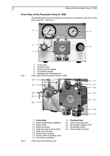
6 Setup of the <strong>Pneumatic</strong> <strong>Pump</strong> K–<strong>1900</strong>Front View of the <strong>Pneumatic</strong> <strong>Pump</strong> K–<strong>1900</strong>All operating elements and hydraulic connections are located on the front of thepump, see Fig. 1 and Fig. 2.342511 <strong>Pump</strong> head2 Flushing Valve3 Eluent pressure gauge4 Air pressure gauge5 Regulator for compressed airFig. 1 Front View of the <strong>Pneumatic</strong> <strong>Pump</strong> K–<strong>1900</strong>1.82.12.22.32.41.71.11.61.31.41.51.2Fig. 21 <strong>Pump</strong> Head 2 Flushing Valve1.1 Piston backflushing capillaries 2.1 Inlets to flushing valve1.2 Eluent inlets 2.2 De-aeration capillary 1/16“1.3 Head set screws 2.3 De-aeration screw1.4 Label with type of pump head 2.4 Eluent outlet to column1.5 Inlets valve housing1.6 Outlets valve housing1.7 Eluent outlets to flushing valve1.8 Connection capillaries<strong>Pump</strong> head and flushing valve