

Betriebsanleitung Allzweckpumpen - Mast Pumpen GmbH
Betriebsanleitung Allzweckpumpen - Mast Pumpen GmbH
Betriebsanleitung Allzweckpumpen - Mast Pumpen GmbH

Sie wollen auch ein ePaper? Erhöhen Sie die Reichweite Ihrer Titel.
YUMPU macht aus Druck-PDFs automatisch weboptimierte ePaper, die Google liebt.
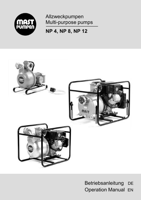
<strong>Allzweckpumpen</strong><br />
Multi-purpose pumps<br />
NP 4, NP 8, NP 12<br />
<strong>Betriebsanleitung</strong> DE<br />
Operation Manual EN
Deutsch<br />
2<br />
Inhaltsverzeichnis<br />
<strong>Allzweckpumpen</strong> NP 4, NP 8, NP 12<br />
1 Konformitätserklärung ____________________________ 3<br />
2 Typenschild _____________________________________ 3<br />
3 Sicherheitshinweise ______________________________ 4<br />
3.1 Kennzeichnung von Hinweisen 4<br />
3.2 Bestimmungsgemäße Verwendung 4<br />
3.3 Sachwidrige Verwendung 4<br />
3.4 Haftung und Gewährleistung 4<br />
3.5 Allgemeine Sicherheitshinweise 5<br />
3.6 Sicherheitshinweise zum Einsatz der Motorpumpen 5<br />
3.7 Sicherheitshinweise zum Einsatz der elektrischen <strong>Pumpen</strong> 5<br />
4 Produktinformation ______________________________ 6<br />
4.1 Produktbeschreibung 6<br />
4.2 Technische Daten 7<br />
5 Inbetriebnahme _________________________________ 8<br />
5.1 Allgemeine Hinweise 8<br />
5.2 Inbetriebnahme mit Benzinmotor 8<br />
5.3 Inbetriebnahme mit Dieselmotor 9<br />
5.4 Inbetriebnahme mit Elektromotor 9<br />
6 Ausserbetriebnahme _____________________________ 9<br />
7 Instandhaltung __________________________________ 10<br />
7.1 Ersatzteilliste NP 4 und NP 8 10<br />
7.2 Ersatzteiliste NP 12 12<br />
7.3 Zerlegen der Pumpe 14<br />
7.4 Zusammenbau der Pumpe 14<br />
7.5 Luftspalteinstellung 15<br />
8 Störungsbehebung ______________________________ 16<br />
9 Entsorgung _____________________________________ 16<br />
Diese <strong>Betriebsanleitung</strong> enthält grundlegende und sicherheitsrelevante<br />
Hinweise, die bei Aufstellung, Betrieb und Instandhaltung zu beachten sind.<br />
Die Pumpe darf nur von ausgebildetem, sachkundigem Personen betrieben<br />
werden. Sie ist vom zuständigen Fachpersonal zu lesen und muss am<br />
Einsatzort ständig verfügbar sein.
1 Konformitätserklärung<br />
Die Firma MAST PUMPEN <strong>GmbH</strong> erklärt in alleiniger Verantwortung, dass die<br />
Produkte<br />
<strong>Allzweckpumpen</strong> NP 4 B, NP 4 BH, NP 4 D, NP 4 DH, NP 4 L, NP 4 E, NP 8 B,<br />
NP 8 D, NP 8 E, NP 12 B, NP 12 D, NP 12 E<br />
auf die sich diese Erklärung bezieht, mit folgenden Normen und normativen<br />
Dokumenten übereinstimmt:<br />
EN 292 T 1 11/91 EN 292-2 06/95 EN 809 10/98<br />
EN 55014 T1-1 02/97 EN 55014 T2 10/97 EN 60335-1 12/98<br />
EN 60335 2-41 04/97 EN 6100-3-2 10/98 EN 61000-3-3 03/96<br />
Gemäß den Bestimmungen der folgenden Richtlinien :<br />
Maschinenrichtlinie 2006/42/EG<br />
Niederspannungsrichtlinie 2006/95/EG<br />
EMV Richtlinien 2004/108/EWG<br />
CE-Kennzeichnungsrichtlinie 93/68/EWG<br />
Aichwald, den 01.09.2009<br />
Ort und Datum der Ausstellung<br />
2 Typenschild<br />
Typ<br />
<strong>Pumpen</strong>nr.<br />
Förderstrom<br />
Förderhöhe<br />
D-73773 Aichwald<br />
Baujahr<br />
Q max<br />
H max<br />
Made in Germany<br />
<strong>Allzweckpumpen</strong> NP 4, NP 8, NP 12<br />
Dipl.Ing. (FH) Rainer <strong>Mast</strong><br />
Name und Unterschrift des Befugten<br />
l/min<br />
Hinweis: Bei Bestellung von Ersatzteilen für die Pumpe wird die<br />
<strong>Pumpen</strong>nummer benötigt, für den Motor Fabrikat und Motornummer.<br />
m<br />
3<br />
Deutsch
Deutsch<br />
4<br />
3 Sicherheitshinweise<br />
3.1 Kennzeichnung von Hinweisen<br />
Das Sicherheitskennzeichen nach DIN 4844-W9 kennzeichnet<br />
Sicherheitshinweise, deren Nichtbeachtung Gefährdungen für<br />
Personen hervorrufen können und somit unbedingt zu beachten<br />
sind.<br />
Dieses Symbol kennzeichnet Sicherheitshinweise, deren Nichtbeachtung<br />
Gefahren für die Pumpe und deren Funktion hervorrufen<br />
können.<br />
3.2 Bestimmungsgemäße Verwendung<br />
Die <strong>Pumpen</strong> dieser Baureihe sind ausschließlich zur Förderung von Schmutz- und<br />
Abwasser ohne schädliche Stoffe, sowie von Heizöl EL und Dieselöl für den mobilen<br />
Einsatz in Außenaufstellung konzipiert.<br />
3.3 Sachwidrige Verwendung<br />
Die Pumpe darf nicht anders verwendet werden, als es im Abschnitt<br />
„Bestimmungsgemäße Verwendung“ beschrieben steht. Jede andere Verwendung<br />
gilt als sachwidrig.<br />
Die Pumpe darf nicht zur Förderung von Fäkalien, Feststoffen mit<br />
Korngrößen > 8 mm (NP 4), > 10 mm (NP 8) und > 20 mm (NP 12),<br />
Säuren und Laugen, brennbaren Flüssigkeiten eingesetzt werden.<br />
Der Motor darf nicht überflutet werden!<br />
<strong>Allzweckpumpen</strong> NP 4, NP 8, NP 12<br />
3.4 Haftung und Gewährleistung<br />
Wir leisten Garantie nach den geltenden Verkaufsbedingungen, jedoch nicht bei<br />
Schäden und Betriebsstörungen durch Nichtbeachtung der <strong>Betriebsanleitung</strong>,<br />
unsachgemäßes Arbeiten an und mit der Pumpe gem. 3.3, die Verwendung nicht<br />
originaler Ersatz- und Zubehörteile sowie durch eigenmächtige Umbauten und<br />
Veränderungen der Pumpe.<br />
Gewährleistungsansprüche sind sofort anzumelden, nachdem der Fehler oder<br />
Mangel festgestellt worden ist. Für Verschleissteile wird keine Gewährleistung<br />
übernommen. Bei Beanstandungen senden Sie die Pumpe nach Absprache bitte<br />
unzerlegt an unser Werk.<br />
Ansprüche auf Schadenersatz, gleich aus welchem Rechtsgrund sie hergeleitet<br />
werden, sind ausgeschlossen. Es muss daher vor immateriellen und materiellen<br />
Schäden durch Ausfall der Pumpe entsprechend vorgesorgt werden.
3.5 Allgemeine Sicherheitshinweise<br />
Die Ausrüstung zum Betrieb der Pumpe muss den geltenden VDE- und<br />
Unfallverhütung Vorschriften entsprechen.<br />
Transportieren Sie die Pumpe immer nur an dem dafür vorgesehenen Tragegriffen.<br />
Lagern Sie die Pumpe nur in trockenen Räumen.<br />
3.6 Sicherheitshinweise zum Einsatz der Motorpumpen<br />
<strong>Pumpen</strong> mit Verbrennungsmotor nur im Freien oder in gut<br />
durchlüfteten Räumen mit dichter Abgasableitung ins Freie<br />
(Abgasschlauch) verwenden.<br />
Vergiftungsgefahr !<br />
Während und nach dem Betrieb Auspufftopf nicht berühren<br />
Verbrennungsgefahr !<br />
Beim Abkuppeln der Schläuche und heißem Motor darauf achten,<br />
daß kein Wasser über Motor und Auspuff gegossen wird<br />
Verbrühungsgefahr !<br />
Gehörschutz im Arbeitsbereich tragen.<br />
<strong>Allzweckpumpen</strong> NP 4, NP 8, NP 12<br />
3.7 Sicherheitshinweise zum Einsatz der elektrischen <strong>Pumpen</strong><br />
Gefährdungen durch elektrische Energie sind auszuschließen (Einzelheiten siehe<br />
z.B. Vorschriften VDE). Überzeugen Sie sich, dass die Steckdose, an die Sie die<br />
Pumpe anschließen wollen, vorschriftsmäßig installiert ist. Sie sollte mit 16A (träge)<br />
abgesichert sein.<br />
Bringen Sie die elektrische Steckverbindungen bei Überschwem-<br />
mungsgefahr im überflutungssicheren Bereich an, und schützen<br />
Sie sie vor Nässe. Pumpe niemals an der Anschlussleitung<br />
ziehen.<br />
Die Anschlussleitung darf nicht unter Zug stehen (Bruchgefahr).<br />
Deshalb lose verlegen, nicht über scharfe Kanten ziehen und<br />
nicht in Türen oder Fenster einklemmen.<br />
Eventuell vorhandene Wendeschalter bei Stromerzeuger, etc. nie<br />
bei laufender Pumpe umschalten.<br />
Bei dauerhaftem Auslösen des Motorschutzes kann sich das Laufrad festgesetzt<br />
oder verklemmt haben. Dazu <strong>Pumpen</strong>gehäuse, Leitapparat und Laufrad reinigen,<br />
bis es wieder frei ist.<br />
5<br />
Deutsch
Deutsch<br />
6<br />
4 Produktinformation<br />
<strong>Allzweckpumpen</strong> NP 4, NP 8, NP 12<br />
4.1 Produktbeschreibung<br />
Diese Allzweckpumpe ist eine einstufige Kreiselpumpe, die mit einem Benzinmotor,<br />
Dieselmotor, oder Elektromotor zu einer Baueinheit zusammengefasst ist<br />
(Monoblockbauweise).<br />
Werkstoffe Pumpe<br />
<strong>Pumpen</strong>welle : nichtrostender Stahl<br />
Laufrad : Sondergusseisen<br />
Leitapparat : Sondergusseisen<br />
Dichtungen : ölbeständige Elastomere<br />
Wellenabdichtung: Gleitringdichtung Kohle / Keramik<br />
Gehäuseteile : Aluminium in seewasserbeständiger<br />
Leichtmetalllegierung nach DIN EN 1706<br />
<strong>Pumpen</strong> mit Elektromotor<br />
Der Asynchronmotor mit Kurzschlussläufer ist für die Betriebsart S 1 (Dauerbetrieb)<br />
nach VDE 0530 ausgelegt, kann aber auch in der Betriebsart S 6 (Durchlauf-Betrieb<br />
mit Aussetzbelastung) eingesetzt werden. Der Stator ist gem. IEC 85 Klasse F(155°)<br />
isoliert.<br />
Motorschutz<br />
Alle <strong>Pumpen</strong> mit Elektromotor sind mit einem Motorschutzstecker (bei 400 V, 3 ~<br />
mit Drehfelderkennung und Phasenwender) ausgerüstet, welcher bei Überlast<br />
abschaltet. Nach Störungs-beseitigung ist die Pumpe wieder am Stecker<br />
einzuschalten. (Achtung: bei Abschaltung stets Netzstecker trennen !)
4.2 Technische Daten<br />
NP 12 E<br />
NP 8 E<br />
NP 4 E<br />
NP 4 L<br />
NP 12 D<br />
NP 8 D<br />
NP 4 DH<br />
NP 4 D<br />
NP 12 B<br />
NP 8 B<br />
NP 4 BH<br />
NP 4 B<br />
Allzweckpumpe<br />
l/min m l/min m l/min m l/min m l/min m l/min m l/min m l/min m l/min m l/min m l/min m l/min m<br />
Förderstrom l/min. 500 0 520 0 850 0 1200 0 500 0 520 0 850 0 1200 0 320 0 400 0 820 0 1200 0<br />
(nach DIN 1944) 440 5 460 15 770 5 1000 10 440 5 460 15 800 5 1100 5 270 5 350 5 760 5 1100 5<br />
bei 380 10 420 20 650 10 700 20 380 10 420 20 680 10 910 10 190 10 255 10 630 10 910 10<br />
Förderhöhe m WS 200 20 300 30 360 20 250 30 200 20 300 30 400 20 530 20 150 12 120 15 400 15 640 15<br />
0 30 0 41 0 30 0 34 0 28 0 41 0 30 0 30 0 15 0 18 0 20 0 20<br />
<strong>Allzweckpumpen</strong> NP 4, NP 8, NP 12<br />
4,8<br />
3600<br />
—<br />
8<br />
G 2"<br />
B<br />
28 34 43 58<br />
102 104<br />
105 110<br />
ca. 1,2 ca. 1,6 ca. 1,6 ca. 2,8 ca.1,2 ca. 1,2 ca. 1,2 ca. 1,8<br />
2,5 3,6 3,6 7,9 3,0 3,0 3,0 5,0<br />
max. 1,1 kg/dm 3<br />
4 - Takt Benzin Diesel<br />
1~ 230 V<br />
3~ 400 V<br />
3,0<br />
4,8 7,5 3,4 3,4 3,4 5,0 0,75 1,5 2,5 4,0<br />
3600<br />
3600 3600 3600 3600 3600 3600 2850 2870 2875 2850<br />
— — — — — — — 5,4 3,3 4,6 7,3<br />
8<br />
10 20 8 8 10 20 8 8 10 20<br />
G 2"<br />
G 2 1/2 " G 2 1/2" G 2" G 2" G 2 1/2" G 2 1/2" G 2" G 2" G 2 1/2" G 2 1/2"<br />
C C<br />
B C C B B C C B B<br />
54x39x42 62x46x50 62x46x50 72x54x55 57x46x50 57x46x50 70x49x55 72x49x55 48x28x43 48x28x43 62x46x50 70x49x55<br />
49 49 58 72 26 29 45 67<br />
104 105 105 105<br />
58 61 65 66<br />
—<br />
— — —<br />
— — — —<br />
bis 8,4 m selbstansaugend<br />
Wasser bis 100°C, Öl bei Raumtemperatur (gesetzl. Vorschriften beachten!)<br />
5 - 8<br />
Motor<br />
Leistung kW<br />
Drehzahl min -1<br />
Nennstrom A<br />
Korndurchlass Ø mm<br />
Anschlussgröße G<br />
STORZ-Kupplung<br />
Maße LxBxH cm<br />
Gewicht kg<br />
Schallleistungspegel dB(A)<br />
Verbrauch L/Std.<br />
Tankinhalt L<br />
Saughöhe m<br />
Flüssigkeitstemperatur °C<br />
Flüssigkeitsdichte kg/dm 3<br />
pH-Wert der Flüssigkeit pH<br />
7<br />
Deutsch
Deutsch<br />
8<br />
5 Inbetriebnahme<br />
5.1 Allgemeine Hinweise<br />
<strong>Allzweckpumpen</strong> NP 4, NP 8, NP 12<br />
5.1.1 Pumpe so nah wie möglich an die Saugstelle auf einen stabilen Untergrund<br />
aufstellen.<br />
Bringen Sie die Pumpe bei Überschwemmungsgefahr in einen<br />
überflutungssicheren Bereich und schützen Sie sie den Motor<br />
vor Nässe.<br />
Vor dem ersten Start das <strong>Pumpen</strong>gehäuse über den<br />
Tassenkrümmer mit Flüssigkeit auffüllen.<br />
5.1.2 Saugleitung, Saugkorb und Druckleitung anschließen. Schläuche nicht<br />
knicken, ggf. Knickschutz verwenden. Nur dicht verschlossene Saugschläuche<br />
verwenden, da sonst kein Vakuum aufgebaut werden kann.<br />
Niemals ohne Saugkorb mit Schutzsieb fördern!<br />
5.1.3 Motor entsprechend der beigefügten <strong>Betriebsanleitung</strong> des Herstellers<br />
starten. Sollte diese nicht zur Hand sein, helfen Ihnen nachfolgende<br />
Hinweise.<br />
Der Saugvorgang läuft selbsttätig ab. Die Förderung beginnt je<br />
nach Saughöhe und Länge der Saugleitung nach ca. 20 bis 300<br />
Sekunden.<br />
5.1.4 Die Pumpe ist trockenlaufsicher. Längerer Trockenlauf sollte jedoch wegen<br />
erhöhtem Verschleiß und als Energiesparmaßnahme vermieden werden.<br />
5.1.5 Bei Einsatz im kalkhaltigem Wasser muss die Pumpe regelmäßig entkalkt<br />
werden.<br />
5.2 Inbetriebnahme mit Benzinmotor<br />
Pumpe mit 4-Takt-Benzinmotor nicht mehr als 15° geneigt aufstellen.<br />
Es kann sonst Schmiermangel auftreten. Ölstand überprüfen!<br />
Starten:<br />
Bei kaltem Motor Hebel auf CHOKE, bei warmen Motor Hebel auf RUN<br />
und Gashebel auf Vollgas stellen. Schalter auf EIN (I). Motor mit Reversierstarter<br />
anwerfen. Seil nicht bis zum Anschlag herausziehen und langsam wieder<br />
zurückführen. Nach dem Anspringen Hebel von CHOKE auf RUN schieben.
<strong>Allzweckpumpen</strong> NP 4, NP 8, NP 12<br />
Zum Abstellen den Motor auf Leerlaufdrehzahl bringen und Schalterauf AUS (0)<br />
stellen.<br />
Tipp: Nach dem abstellen den Schalter wieder auf EIN stellen, dann ist beim nächsten<br />
Start die Zündung nicht versehentlich unterbrochen.<br />
Bitte auch beiliegende <strong>Betriebsanleitung</strong> des Motorenherstellers beachten!<br />
5.3 Inbetriebnahme mit Dieselmotor<br />
Pumpe mit Dieselmotor nicht mehr als 20 ° geneigt aufstellen.<br />
Es kann sonst Schmiermangel auftreten. Ölstand überprüfen!<br />
Starten:<br />
Drehzahlhebel auf Vollgas stellen und Motor mit Reversierstarter<br />
anwerfen, dazu das Startseil mit stätig zunehmender Beschleunigung<br />
kraftvoll ziehen und mit der Hand wieder zurückführen.<br />
Zum Abstellen Drehzahlhebel bis zum Anschlag auf STOP zurücknehmen.<br />
Bitte auch beiliegende <strong>Betriebsanleitung</strong> des Motorenherstellers beachten!<br />
5.4 Inbetriebnahme mit Elektromotor<br />
Die Pumpe mit 1~ 230 V Elektromotor läuft sofort nach dem Einstecken des<br />
Motorschutzsteckers in die Steckdose.<br />
Bei 3~ 400 V Elektromotoren ist die Pumpe mit einem Motorschutzstecker mit einer<br />
Drehrichtungskontrolle und Phasenwender ausgestattet.<br />
Den Stecker in die Steckdose einstecken und kurz einschalten.<br />
Drehrichtung des Lüfters muss mit dem Pfeil auf der Lüfterhaube<br />
übereinstimmen und die rote Lampe darf am Motorschutzstecker<br />
nicht aufleuchten.<br />
Bei falscher Drehrichtung – Stecker umpolen. Dazu Stecker herausziehen,<br />
Schraubendreher zwischen dem drehbaren Stiftpaar in der Auskerbung ansetzen,<br />
leicht eindrücken und Stiftpaar 180° drehen. Motorschutzstecker wieder einstecken<br />
und einschalten.<br />
6 Ausserbetriebnahme<br />
Nach dem Einsatz mit klarem Wasser spülen und etwa 1 Minute trocken laufen<br />
lassen und durch Lösen der Verschlussschraube an der Gehäuseunterseite<br />
entleeren. Dadurch wird ein Festbacken des Laufrades durch Lehm- oder Zementwasser<br />
verhindert.<br />
Sollte die Pumpe bei Frost festsitzen, löst sich das Laufrad durch eingefülltes<br />
warmes Wasser wieder.<br />
9<br />
Deutsch
Deutsch English<br />
7 Instandhaltung / Repairs<br />
10<br />
7.1 Ersatzteilliste NP 4 und NP 8 / Spare parts list NP 4 and NP 8<br />
Please report item-number and pump-number when ordering parts.<br />
Bei Bestellungen bitte Artikelnummer und <strong>Pumpen</strong>nummer angeben.
NP 4 NP 8 NP 4 NP 8<br />
Pos. Benennung Description St. Artikel / item St. Artikel / item Pos. Benennung Description St. Artikel / item St. Artikel / item<br />
1 Deckel pump cap 1 0400110 1 0800110 13 Verschlussschraube drain plug 1 0402301 1 0402301<br />
2 Kerbstift socket pin 1 DIN 1474 5x16 1 DIN 1474 5x16 14 Sechskantschraube hexagon bolt 11 DIN 933 M6x25 11 DIN 933 M6x25<br />
3 O - Ring o - ring 15 Sechskantschraube hexagon bolt 1 DIN 933 M6x16 1 DIN 933 M6x20<br />
4 Gegenring counter ring 1 0405101 1 0805101 16 Sechskantmutter nut 11 DIN 934 M6 11 DIN 934 M6<br />
5 Gleitring face seal 17 Federscheibe curved washer 12 DIN 137 A6 12 DIN 137 A6<br />
6 Laufrad impeller NP 4 B/D 1 0400904 NP 8 B 1 0800908 18 Druckkrümmer Tasse delivery bend 1 0401602 1 0801604<br />
NP 4 BH 0400908 NP 8 D 0800907 19 Dichtung Saug gasket suction 1 DIN 14321-4-DS 1 DIN 14322-4-DS<br />
NP 4 DH 0400909 NP 8 E 0800910 20 Festkupplung Saug coupling suction 1 DIN 14307-CS 1 DIN 14308-BS<br />
NP 4 L 0400912 21 Flachdichtring gasket 2 DIN 14307-3 2 DIN 14308-3<br />
NP 4 E 0400911 22 Saugkrümmer suction bend 1 0401600 1 0801600<br />
7 Saugventil suction valve NP 4 BH/DH 1 0401000 1 0401000 23 Sechskantschraube hexagon bolt 8 DIN 933 M6x25 8 DIN 933 M8x25<br />
8 Leitapparat diffuser NP 4 B/D 1 0401108 1 0801101 24 Federscheibe curved washer 8 DIN 137 A6 8 DIN 137 A8<br />
NP 4 BH 0401107 25 Dichtung Druck gasket pressure 1 DIN 14302-4 1 DIN 14303-4<br />
NP 4 DH 0401106 26 Festkupplung Druck coupling pressure 1 DIN 14307-CD 1 DIN 14308-BD<br />
NP 4 L 0401109 27 O - Ring o - ring 2 NBR 57 x 3 2 NBR 67 x 3<br />
NP 4 E 0401105 28 Verschlussschraube plug filler 1 0401621 1 0401621<br />
9 O - Ring o - ring 1 NBR 50 x 3 1 NBR 67 x 3 29 O - Ring o - ring 1 NBR 41 x 3 1 NBR 41 x 3<br />
10 O - Ring o - ring 1 NBR 235 x 4 1 NBR 265 x 4<br />
11 Gehäuse housing 1 0401400 1 0801400<br />
12 O - Ring o - ring 1 NBR 18 x 2,5 1 NBR 18 x 2,5<br />
Die nicht dargestellten Ersatzteile wie Motor, Flansch, Rahmen, etc. bitten wir mit Angabe von <strong>Pumpen</strong>typ und <strong>Pumpen</strong>nummer zu bestellen.<br />
Motorenteile unbedingt mit Angabe von Motortyp und der Motornummer bestellen.<br />
Please order spare parts not shown in list e.g. engine, flange, frame, etc. by stating type of pump and number of pump.<br />
Please order spare parts of engine by stating type of engine and number of engine.<br />
11<br />
Deutsch<br />
English
Deutsch English<br />
7.2 Ersatzteilliste NP 12 / Spare parts list NP 12<br />
12<br />
Bei Bestellungen bitte Artikelnummer und <strong>Pumpen</strong>nummer angeben. Please report item-number and pump-number when ordering parts.
Pos. Benennung Description St. Artikel / item Pos. Benennung Description St. Artikel / item<br />
1 4 - Takt Motor 4 - stroke engine NP 12 B 1 B&St. 185432 21 Dichtung gasket 1 DIN 14308-3<br />
Dieselmotor Diesel engine NP 12 D HATZ 1B30 22 Sechskantschraube hexagon bolt 2 DIN 933 M10 x 30<br />
Elektromotor 3~ A.C. motor NP 12 E AF 112M/2A-11 23 Federscheibe curved spring washer 6 DIN 137 A10<br />
2 Flansch flunge NP 12 B 1 1202610 24 Gewindeflansch screwed flange 1 1201630<br />
(Hatz 1B30) NP 12 D 1202621 25 Rückschlagklappe non-return flap 1 1201610<br />
NP 12 E 1202640 26 Ringmutter ring nut 4 DIN 582 M10<br />
3 Distanzhülse distance ring NP 12 B 1 1202500 27 Dichtung gasket 1 1201501<br />
motor shaft NP 12 D 1202501 28 Druckkrümmer Tasse deliery bend 1 0801604<br />
4 Gehäuse pump housing 1 1201402 29 Festkupplung B Druck coupling pressure 1 DIN 14308-BD<br />
5 Stiftschraube stud 4 DIN 939 M 10 x 120 30 Druckdichtung gasket pressure 1 DIN 14303-4<br />
6 O - Ring o - ring NBR 305 x 5 31 O-Ring o - ring 1 NBR 41 x 3<br />
7 O - Ring o - ring 32 Verschlussschraube plug filler 1 0401621<br />
8 Gegenring counter-ring 1 1205100 33 Sechskantschraube hexagon bolt 8 DIN 933 M8x25<br />
9 Gleitring mechanical seal 34 Federscheibe curved spring washer 12 DIN 137 A8<br />
10 Laufrad impeller NP 12 B 1 1200902 35 Sechskantschraube hexagon bolt 4 DIN 933 5/16"<br />
NP 12 D 1200901 Sechskantschraube hexagon bolt 4 DIN 931 M10 x 40<br />
NP 12 E 1200901 36 Sechskantschraube hexagon bolt 4 DIN 933 M10 x 35<br />
11 Leitapparat diffuser 1 1201105 37 Träger carrier NP 12 B 2 1203314<br />
12 Saugventil* suction valve 1 0801000 NP 12 D 2 1203346<br />
13 O - Ring o - ring 1 NBR 67 x 3 NP 12 E 1 1203331<br />
14 Deckel pump cap 1 1200104 38 Gummimetallpuffer rubber-metal-buffer 4 1203307<br />
15 O - Ring NBR 32 X 2 o - ring 1 1202200 39 Sechsmutter hexagon nut 4 DIN 934 M10<br />
16 Verschlussschraube plug 1 1202300 40 Rahmen frame NP 12 B 1 1203315<br />
17 Typenschild type plate NP 12 B 1 0010220 (Hatz 1B30) (Hatz 1B30) NP 12 D 1203345<br />
NP 12 D 0010230 NP 12 E 1203344<br />
NP 12 E 0010240 41 Federring spring ring 8 DIN 127 A10<br />
18 Kerbnagel socket pin 4 DIN 1476 3 x 4 42 Sechskantschraube hexagon bolt 4 DIN 933 M10 x 16<br />
19 Saugdichtung gasket suction 1 DIN 14322-4-DS 43 Tragegriffe handle 4 0803351<br />
20 Festkupplung B-Saug coupling suction 1 DIN 14308-BS 44 Sechkantmutter hexagon nut 4 DIN 934 M8<br />
*nur bis <strong>Pumpen</strong>-Nr. 3683 verbaut / up to pump-n°3683 only<br />
Die nicht dargestellten Ersatzteile wie Motor, Flansch, Rahmen, etc. bitten wir mit Angabe von <strong>Pumpen</strong>typ und <strong>Pumpen</strong>nummer zu bestellen.<br />
Motorenteile unbedingt mit Angabe von Motortyp und der Motornummer bestellen.<br />
Please order spare parts not shown in list e.g. engine, flange, frame, etc. by stating type of pump and number of pump.<br />
Please order spare parts of engine by stating type of engine and number of engine.<br />
13<br />
Deutsch<br />
English
Deutsch<br />
7.3 Zerlegen der Pumpe<br />
Instandsetzungsarbeiten dürfen nur von fachkundigen Personen<br />
durchgeführt werden.<br />
Bei eigenmächtigen Umbau oder Instandsetzung erlischt die<br />
Gewährleistung.<br />
Für Schäden die auf fehlerhaft durchgeführte Instandsetzung<br />
zurückzuführen sind, wird keine Haftung übernommen.<br />
Nur bei <strong>Pumpen</strong> mit E-Motor: Bei Arbeiten an der Pumpe<br />
grundsätzlich Netzstecker aus der Steckdose ziehen.<br />
Hinweis: Im Folgenden gilt erstgenannte Pos. in Klammern für Reihe NP 4 und NP 8,<br />
zweitgenannte Pos. für Reihe NP 12, z.B. (Pos. 4 / Pos. 10).<br />
7.3.1 Pumpe durch Öffnen der Verschlussschraube (Pos. 13 / Pos. 16) entleeren.<br />
7.3.2 Gehäuse (Pos. 11 / Pos. 14) durch Lösen der Schrauben (Pos. 15 M6 / Pos 26<br />
Ringmutter) abnehmen.<br />
7.3.3 Leitapparat (Pos. 8 / Pos. 11) herausziehen.<br />
7.3.4 Zum Auswechseln der Wellenabdichtung Pumpe waagerecht stellen. Bei<br />
<strong>Pumpen</strong> mit E-Motor bei manuellen Arbeiten mit dem Schraubenschlüssel<br />
Lüftergehäuse mit Lüfterrad demontieren um bei Demontage des Laufrads<br />
die Motorwelle fixieren zu können.<br />
7.3.5 Laufrad (Pos. 6 / Pos. 10) mit Gleitring (Pos. 5 / Pos. 9) abschrauben<br />
(Rechtsgewinde, SW 17 oder 19), anschließend Gleitring von Laufrad abziehen.<br />
7.3.6 Gegenring (Pos. 4, Pos. 8) und O-Ring (Pos. 3, Pos. 7) aus dem Deckel<br />
(Pos. 1 / Pos 4) herausdrücken.<br />
7.4 Zusammenbau der Pumpe<br />
7.4.1 Der Zusammenbau wird in umgekehrter Reihenfolge vorgenommen.<br />
7.4.2 Beim Einbau des Gegenringes (Pos. 4, Pos. 8) den darunter einzusetzenden<br />
O-Ring (Pos. 3, Pos. 7) außen mit Fett benetzen (Achung: Gleitfläche der<br />
Gleitringdichtung darf nicht mit Fett benetzt werden !), dann den Gegenring<br />
vorsichtig in den Sitz drücken. Anschließend Gleitring auf den Schaft des<br />
Laufrades schieben und Laufrad wieder auf Motorwelle aufdrehen.<br />
7.4.3 Gleitfläche des Gegenringes (Pos. 4, Pos. 8) und des Gleitringes (Pos. 5,<br />
Pos. 8) müssen staub- und fettfrei montiert werden.<br />
7.4.4 Luftspalteinstellung gem. 7.5 nächste Seite durchführen.<br />
7.4.5 Funktionsprüfung des komplette Aggregats durchführen.<br />
14<br />
<strong>Allzweckpumpen</strong> NP 4, NP 8, NP 12
7.5 Luftspalteinstellung<br />
<strong>Allzweckpumpen</strong> NP 4, NP 8, NP 12<br />
Die Länge der Distanzhülse wird individuell auf jeder Motor abgestimmt.<br />
Der Spalt vor und hinter dem Laufrad sollte bei ca. 0,3 mm liegen.<br />
Luftspalt<br />
Leitapparat<br />
Laufrad<br />
15<br />
Deutsch
Deutsch<br />
16<br />
8 Störungsbehebung<br />
Pumpe saugt nicht an<br />
Mögliche Ursache Behebung<br />
Im <strong>Pumpen</strong>gehäuse befidnet sich<br />
kein oder zu wenig Wasser/Flüssigkeit<br />
9 Entsorgung<br />
<strong>Allzweckpumpen</strong> NP 4, NP 8, NP 12<br />
<strong>Pumpen</strong>gehäuse auffüllen<br />
Saugleitung ist undicht Kupplungsdichtungen auf Beschädigungen<br />
überprüfen und nötigenfalls austauschen –<br />
evtl. Saugschlauch auswechseln<br />
Die Saughöhe ist zu groß Pumpe näher an den Wasserspiegel stellen<br />
Es wurde ohne Saugkorb gepumpt.<br />
Die Pumpe ist durch grobe<br />
Fremdkörper (Steine, Holzstücke,<br />
etc.) verstopft.<br />
Pumpe bringt nicht die gewünschte Leistung<br />
Mögliche Ursache Behebung<br />
Nur bei <strong>Pumpen</strong> mit Elektromotor<br />
3~ 400 V: Falsche Drehrichtung<br />
Der Saugkorb sitzt im Schlamm<br />
fest<br />
<strong>Pumpen</strong>gehäuse abschrauben, Leitapparat<br />
abnehmen und Pumpe reinigen. Meistens<br />
fallen beim Abschrauben des <strong>Pumpen</strong>-<br />
gehäuses die Steine oder Holzstücke bereits<br />
hinaus<br />
Motorschutzstecker durchd rehen der<br />
Stifte umpolen (siehe auch 5.4)<br />
Saugschlauch so weit herausziehen,<br />
dass die Pumpe dünnflüssiges Fördergut<br />
bekommt<br />
Schlauch ist abgeknickt Schlauchleitung besser verlegen<br />
Durch Eindicken der Flüssigkeit<br />
wird das spezifische Gewicht im<br />
Verhältnis zur Saughöhe zu groß<br />
Laufrad oder Leitapparat sind<br />
verschlissen<br />
Wasser beigefügen oder Saughöhe<br />
vermindern. Aufrühren des Förderguts<br />
von Hand oder durch Umpumpen.<br />
Verschlissene Teile auswechseln<br />
Dieses Produkt sowie Teile davon müssen bei den örtlichen Entsorgungsstellen<br />
oder beim Hersteller entsorgt werden.
Directory<br />
Multi-purpose pump NP 4, NP 8, NP 12<br />
1 Declaration of comformity _______________________ 18<br />
2 Typeplate _____________________________________ 18<br />
3 Safety instructions _____________________________ 19<br />
3.1 Signposting 19<br />
3.2 Intended use 19<br />
3.3 Improper use 19<br />
3.4 Liability and warranty 19<br />
3.5 General safety instructions 20<br />
3.6 Safety instructions pumps with engine 20<br />
3.7 Safety instructions pumps with electric motor 20<br />
4 Product information ____________________________ 21<br />
4.1 Product description 21<br />
4.2 Technical characteristics 22<br />
5 Startup _______________________________________ 23<br />
5.1 General information 23<br />
5.2 Startup with petrol engine 23<br />
5.3 Startup with Diesel engine 24<br />
5.4 Startup with electric motor 24<br />
6 Shutdown ____________________________________ 24<br />
7 Repairs ______________________________________ 10<br />
7.1 Spare parts list NP 4 and NP 8 11<br />
7.2 Spare parts lists NP 12 13<br />
7.3 Disassembling of the pump 25<br />
7.4 Assembling of the pump 25<br />
7.5 Adjusting air gap 26<br />
8 Troubleshooting _______________________________ 27<br />
9 Disposal 27<br />
These operating instructions contain general and security-relevant<br />
information. Before operation they should be studied carefully by the<br />
service technican and the responsibles. This handbook should always<br />
be available at the point of application.<br />
17<br />
English
English<br />
18<br />
1 Declaration of conformity<br />
Multi-purpose pump NP 4, NP 8, NP 12<br />
The MAST PUMPEN company declares under our sole responsibility that the<br />
products,<br />
<strong>Allzweckpumpen</strong> NP 4 B, NP 4 BH, NP 4 D, NP 4 DH, NP 4 L, NP 4 E, NP 8 B,<br />
NP 8 D, NP 8 E, NP 12 B, NP 12 D, NP 12 E<br />
to which this declaration relates, are in conformity with following standards and<br />
directives:<br />
EN 292 T 1 11/91 EN 292-2 06/95 EN 809 10/98<br />
EN 55014 T1-1 02/97 EN 55014 T2 10/97 EN 60335-1 12/98<br />
EN 60335 2-41 04/97 EN 6100-3-2 10/98 EN 61000-3-3 03/96<br />
According to the following directives:<br />
Machinery directive 2006/42/EG<br />
Low voltage directive 2006/95/EG<br />
Electromagnetic compatibility 2004/108/EWG<br />
CE-designation directive 93/68/EWG<br />
Aichwald, 01.09.2009<br />
City and date of issue<br />
2 Typeplate<br />
Type description<br />
Pump serial-n°<br />
Delivery rate Q<br />
Delivery height H<br />
Typ<br />
<strong>Pumpen</strong>nr.<br />
Förderstrom<br />
Förderhöhe<br />
D-73773 Aichwald<br />
Baujahr<br />
Q max<br />
H max<br />
Made in Germany<br />
Dipl.Ing. (FH) Rainer <strong>Mast</strong><br />
Name and sign of responsible<br />
l/min<br />
Ref.: Pump serial number is required for ordering spare-parts. Motor / engine<br />
brand name and serial number is required for motor / engine spare parts.<br />
m<br />
Year of manufacture
3 Safety instructions<br />
3.1 Signposting<br />
Multi-purpose pump NP 4, NP 8, NP 12<br />
The safety sign acc. to DIN 4844-W9 indicates safety instructions<br />
whose no observance can cause hazards to persons. They must be<br />
followed strictly.<br />
This sign indicates safety instructions whose no observance can<br />
cause hazards to the pump and its operation.<br />
3.2 Intended use<br />
The pumps of this line-up are designed for pumping wastewater und effluents<br />
without aggressive ingredients, light fuel oil and Diesel oil for mobile application<br />
outside the water.<br />
3.3 Improper use<br />
The pump must not be used for purposes other than intended. It may only be used<br />
for applications described in the section 3.2 (intended use). Any other application is<br />
deemed to be as an improper use.<br />
The pump must not be used to deliver faeces, solids > 8 mm (types<br />
NP 4), > 10 mm (types NP 8), > 20 mm (types NP 12), acids and<br />
alkalis, inflammable liquids.<br />
The engine / electic motor must not be flooded!<br />
3.4 Liability and warranty<br />
No liability is accepted for damage and disruption attributable to non-compliance<br />
with the operating instructions, improper use discribed in the section 3.3, or<br />
unauthorized modifications and the use of non-original spare parts and accessories<br />
by the user. No compensation for damages is accepted, regardless of the legalground.<br />
Appropriate arrangements should be taken to avert material or non-material<br />
damage in the event of pump failure, e.g., by installing a second pump, a mainsindependent<br />
alarm system or other accessories.<br />
Warranty claims are to be notified immediately after the fault or defect has been<br />
ascertained. There is no warranty for wearing parts.<br />
19<br />
English
English<br />
20<br />
Multi-purpose pump NP 4, NP 8, NP 12<br />
3.5 General safety instructions<br />
The electrical equipment to run the pump complies with the current VDE (the<br />
German Association for Electrical, Electronic & Information Technologies) and<br />
accident prevention regulations.<br />
Handle the pump with the mounted carry handle only. Store the pump in dry rooms<br />
only.<br />
3.6 Safety instructions pumps with engine<br />
Pumps powerd by a combustion engine must be operated<br />
outdoor only, or in well aired rooms in combination with a sealed<br />
outdoor exhaust hose. Risk of poisining !<br />
Never touch the muffler during and right after application of the<br />
pump. Risk of erythema !<br />
Do not water engine and exhaust when decoupling hoses from<br />
the pump right after application when the engine is still hot.<br />
Risk of scalding !<br />
Always use earplugs during application.<br />
3.7 Safety instructions pumps with electric motor<br />
Danger from power supply has to be eliminated (details see e.g. VDE or local safety<br />
regulations).<br />
The power supply to which the pump will be connected must be installed properly<br />
acc. to the current safety regulations protected by a 16 A (slow-acting) fuse.<br />
Keep electrical connections dry. If there is a risk of flooding,<br />
move electrical connections to a flood protected area to protect<br />
them from wetness. Never move or gibbet the pump by using the<br />
power connection cable.<br />
The connection cable must not be in tension (Risk of cable break).<br />
Put the cable loosely, do not pull it over sharp edges and do not<br />
clamp it into doors and windows.<br />
If the generator has a reversing switch, never turn it when the<br />
pump is running.<br />
If the motor protection switch permanently switches off, the impeller could be<br />
blocked by solids. Disconnect the pump from the power supply, disassemble the<br />
motorhousing, diffuser and impeller, remove the solids and clean it.
4 Product information<br />
Multi-purpose pump NP 4, NP 8, NP 12<br />
4.1 Product description<br />
This Multi-purpose pump is designed as a monobloc single-stage centrifugal pump,<br />
powered by a petrol engine, Diesel engine, or a electric motor.<br />
Materials pump<br />
Pump shaft : stainless steel<br />
Impeller : special cast iron<br />
Diffuser : special cast iron<br />
Gaskets : mineral oil-resistant elastomeres<br />
Shaft seal : face seal carbon / carbid<br />
Pump casing : Aluminium alloy seewater resistant acc. to DIN EN 1706<br />
Pumps with electric motor<br />
The asynchronous squirrel-cage motor is designed for S 1 duty (continuous duty)<br />
acc. to VDE 0530, however, it can also be used for S 6 duty (continuous duty with<br />
intermittent duty).<br />
Motor protection<br />
All Pumps with electric motor are equipped with a motor protection plug (at 400 V,<br />
3 ~ additionally with rotating direction control and phase changer), that turns off the<br />
pump in the case of an overload. After troubleshooting, the pump can be switched<br />
on again. (Warning: Always disconnect the power supply when working on the<br />
pump!)<br />
21<br />
English
English<br />
22<br />
Engine / Motor<br />
Output kW<br />
Speed r.p.m.<br />
Rated current A<br />
Grain passage Ø mm<br />
Connection size G<br />
STORZ-Coupling<br />
Dimensions LxWxH cm<br />
Weight kg<br />
Sound power level dB(A)<br />
Consumption ca. l(gal)/h<br />
Tank capacity l (gal)<br />
Suction height m (ft.)<br />
liquid temperature °C (°F)<br />
liquid density kg/dm 3<br />
pH-value of liquid pH<br />
5 - 8<br />
3600<br />
—<br />
8<br />
G 2"<br />
48x28x43 48x28x43<br />
34<br />
104<br />
1,2 (0,3) 1,6 (0,3) 1,6 (0,3)<br />
1,2 (0,3) 1,2 (0,3)<br />
2,5 (0,6) 3,6 (0,8) 3,6 (0,8) 7,9 (1,7) 3,0 (0,8) 3,0 (0,8) 3,0 (0,8) 5,0 (1,3)<br />
—<br />
max. 1,1 kg/dm 3<br />
4 - stroke petrol Diesel 1~ 230 V<br />
3~ 400 V<br />
3,0 4,8 4,8 7,5 3,4 3,4 3,4 5,0 0,75 1,5 2,5 4,0<br />
3600<br />
3600 3600 3600 3600 3600 3600 2850 2870 2875 2850<br />
— — — — — — — 5,4 3,3 4,6 7,3<br />
8<br />
10 20 8 8 10 20 8 8 10<br />
20<br />
G 2" G 2 1/2 " G 2 1/2" G 2" G 2" G 2 1/2" G 2 1/2" G 2" G 2" G 2 1/2" G 2 1/2"<br />
C C B B C C B B C C B B<br />
54x39x42 62x46x50 62x46x50 72x54x55 57x46x50 57x46x50 70x49x55 72x49x55<br />
62x46x50 70x49x55<br />
28<br />
43 58 49 49 58 72 26 29 45 67<br />
102<br />
104 105 105 105 105 110 58 61 65 66<br />
2,8 (0,8) 1,2 (0,3) 1,8 (0,5) — — — —<br />
—<br />
— —<br />
up to 8,4 m (26 ft.) self-priming<br />
water up to 100°C (212°F), oil at room temperature ( mind statutory provisions!)<br />
Multi-purpose pump NP 4, NP 8, NP 12<br />
l/min m l/min m l/min m l/min m l/min m l/min m l/min m l/min m l/min m l/min m l/min m l/min m<br />
Pumping rate l/min. 500 0 520 0 850 0 1200 0 500 0 520 0 850 0 1200 0 320 0 400 0 820 0 1200 0<br />
(acc. to DIN 1944) 440 5 460 15 770 5 1000 10 440 5 460 15 800 5 1100 5 270 5 350 5 760 5 1100 5<br />
at a 380 10 420 20 650 10 700 20 380 10 420 20 680 10 910 10 190 10 255 10 630 10 910 10<br />
pumping head m wc 200 20 300 30 360 20 250 30 200 20 300 30 400 20 530 20 150 12 120 15 400 15 640 15<br />
( 1 l = 0,26 gal / 1 m = 3,28 ft.) 0 30 0 41 0 30 0 34 0 28 0 41 0 30 0 30 0 15 0 18 0 20 0 20<br />
Multi-purpose pump<br />
NP 4 B<br />
NP 4 BH<br />
NP 8 B<br />
NP 12 B<br />
NP 4 D NP 4 DH NP 8 D NP 12 D NP 4 L NP 4 E NP 8 E NP 12 E
5 Startup<br />
5.1 General information<br />
5.1.1 Set up the pump as close as possible to the suction point on a stable surface.<br />
The pump has to be positioned within a flood-protected area.<br />
The engine has to be protected from moistness.<br />
Before application, the pump casing has to be filled with<br />
water through the cup on top of the casing.<br />
5.1.2 Connect suction hose, suction basket and pressure hose. Do not kinck the<br />
hose, use an anti-kinck protection (MAST item-nr.: 501, optional), if needed. Use<br />
only airtight hoses, otherwise the suction process could fail.<br />
Never run the pump without suction basket!<br />
5.1.3 Start the engine as described in the attached operation manual of the<br />
engine manufacturer. If not available, refer to the following chapters.<br />
The suction process starts automatically. The delivery starts<br />
after 20 to 300 sec., depending on suction depth and length of<br />
the suction hose.<br />
5.1.4 The pump is dry-running safe. Though, a longer period of dry-running should<br />
be avoided, because of consequential higher wear-out and for power saving<br />
reasons.<br />
5.1.5 When delivering calcareous water, the pump has to be decalsified frequently.<br />
5.2 Startup with petrol engine<br />
Multi-purpose pump NP 4, NP 8, NP 12<br />
The pumps with 4-stroke petrol engine must be positioned at<br />
inclination below 15°. Above, lubrication may fail.<br />
Check the oil-level before starting!<br />
Engine start:<br />
At cold engine, shift the lever to „CHOKE“. At warm engine, shift it to „RUN“,<br />
and put the speed lever to full power („rabbit“). The power switch has to be pushed to<br />
ON / EIN (I). Actuate the engine with the hand starting rope. Do not the pull the rope<br />
to the end, and return it smoothly. After the engine has started, put the shifter from<br />
„CHOKE“ to „RUN“.<br />
23<br />
English
English<br />
24<br />
To stop the engine reduce the speed to engine idiling („turtle“) and push the red<br />
rocker switch to OFF / AUS (0).<br />
Tip: Set the rocker switch to EIN / ON (I) after turning off the pump, so the ignition is<br />
not disconnected by accident at the next starting.<br />
Please take note to the attached engine operation manual for further<br />
information!<br />
5.3 Startup with Diesel engine<br />
The pumps with Diesel engine must be positioned at inclination<br />
below 20 °. Above, lubrication may fail.<br />
Check the oil-level before starting!<br />
Startup:<br />
Shift the speed lever to full power („rabbit“) and actuate the engine with the starter<br />
rope. Pull the rope powerful at increasing speed and return it smoothly.<br />
Turn off the pump by shifting the speed lever to STOP.<br />
Please take note to the attached engine operation manual for further<br />
information!<br />
5.4 Startup with electric motor<br />
Pumps with 1~ 230 V electric motor starts immediately after connecting the motor<br />
protection plug to the mains.<br />
Pumps with 3~ 400 V electric motor are equipped with motor protection plug with<br />
integrated phase changer and control light.<br />
At first, connect the plug to the mains and switch on the pump shortly to control sense<br />
of rotation.<br />
The sense of rotation of the fan impeller must correspond to the<br />
direction of the arrow on the fan casing, and the red light on the<br />
motor protection plug must not flash up.<br />
Reverse the polarity in case of a wrong sense of rotation. Therefore, disconnect the<br />
plug from the mains. Rotate the bolds of the plug about 180° by using a screw driver.<br />
For that, push the notch between the bolds smoothly by a screw driver, and rotate<br />
them till they click into place again. After that, connect the plug to the mains and start<br />
again.<br />
6 Shutdown<br />
Multi-purpose pump NP 4, NP 8, NP 12<br />
Flush the casing with clear water after application and run the pump dry for about a<br />
minute. Unscrew the lock screw at the bottom of the pump casing for dewatering it.<br />
With this, the impeller will not be blocked by drying-out solids at the next start after<br />
storage. If the pump is blocked by frozen water, fill in hot water to release the<br />
impeller.
7.3 Disassembling of the pump<br />
Multi-purpose pump NP 4, NP 8, NP 12<br />
Repairs must be accomplished by authorized persons only.<br />
Warranty claims expire with unauthorized repairs or arbitrary<br />
modifications. Any liability for consequential damages such as<br />
personal damages, property and material damages caused by<br />
inproper repairs is excluded.<br />
For pumps with electric motor only: The power supply must be<br />
disconnected for all services always.<br />
Note: Following, the first stated pos. in brackets is valid for range NP 4 and NP 8,<br />
the second stated pos. for range NP 12, e.g. (Pos. 4 / Pos. 10).<br />
7.3.1 Dewater the pump by unscrewing the lock screw at the bottom of the pump<br />
(pos. 13 / pos. 16).<br />
7.3.2 Dismantle the casing (pos. 11 / pos. 14) by unbolt the screws (pos. 15 M6 /<br />
pos. 26 ring nut).<br />
7.3.3 Pull out the diffuser (pos. 8 / pos. 11).<br />
7.3.4 Position the pump horizontally for replacing the shaft seal. For pumps with<br />
electric motor only: dismantle fan casing and fan impeller to allow a blocking of<br />
the shaft for demounting the impeller later.<br />
7.3.5 Demount impeller (pos. 6 / pos. 10) and seal ring (pos. 5 / pos. 9) (right-hand<br />
thread, wrench size 17 or 19), and take-off the seal ring from the impeller.<br />
7.3.6 Push out the counter ring (pos. 4 / pos. 8) and the o-ring (pos. 3 / pos. 7) from<br />
the back casing.<br />
7.4 Assembling of the pump<br />
7.4.1 The assembling of the pump is the reverse order of the disassembling explained<br />
above.<br />
7.4.2 When mounting the counter ring (pos. 4 / pos. 8) grease the outer side of the<br />
thereunder mounted o-ring (pos. 3 / pos. 7) (Caution: the sliding surface of<br />
the shaft seal must not be greased!). After that, push the seal ring on the<br />
shaft of the impeller and mount it on the engine/motor shaft.<br />
7.4.3 When installing, keep the sliding surfaces of the counter ring (pos. 4 / pos. 8)<br />
and the shaft seal (pos. 5 / pos. 8) dust-free and greaseless.<br />
7.4.4 Adjust the air gap between impeller and diffuser as shown in 7.5 next page.<br />
7.4.5 Run a performance check of the complete unit.<br />
25<br />
English
English<br />
26<br />
7.5 Adjusting air gap<br />
Multi-purpose pump NP 4, NP 8, NP 12<br />
The length of the distance tube has to be adjusted indiviually for each engine.<br />
The gap before and behind the impeller should be approx. 0.3 mm.<br />
Air gap<br />
Diffuser<br />
Impeller
8 Troubleshooting<br />
Pump does not deliver<br />
Trouble Troubleshooting<br />
No or too less water in the pump<br />
casing<br />
9 Disposal<br />
<strong>Allzweckpumpen</strong> NP 4, NP 8, NP 12<br />
Fill water into the pump casing<br />
Suction hose is leaky Check if couplings are damaged and<br />
replace it, or replace the suction hose<br />
Suction depth is too high Position pump close to the water<br />
Pumps has been applicated without<br />
suction basket. The pump is blocked<br />
by bigger solids (stones, wooden<br />
parts, etc.)<br />
Pump does not achieve the rated output<br />
Trouble Troubleshooting<br />
Pumps with 3~ 400 V electric<br />
motor only: pump has wrong<br />
sense of rotation<br />
The suction basket is blocked by<br />
solids<br />
Dismantle the pump casing by<br />
unbolting the screws (see also in<br />
chapter 7.3), pull off the diffuser, and<br />
clean the pump<br />
Change sense of rotation at the<br />
motor protection plug (see more at<br />
chapter 5.4)<br />
Pull out the suction hose from the<br />
heavy polluted area in a lighter<br />
polluted area<br />
The pressure hose is kinked Change position of the hose<br />
Liquid is thickening, the specific<br />
density ratio to the suction<br />
depth is inappropriate<br />
Add water or decrease suction<br />
depth<br />
Impeller or/and diffuser is worn out Replace worn out parts<br />
This product and parts of it have to be disposed at your local disposal area or at<br />
the manufacturer.<br />
27<br />
English
www.mast-pumpen.de<br />
MAST PUMPEN <strong>GmbH</strong><br />
pump manufacturer<br />
Mörikestrasse 1<br />
D-73773 Aichwald (Germany)<br />
Phone +49 711 93 67 04 - 0<br />
B28 11.10


