TakeUp TU630/900 - Mobac GmbH
TakeUp TU630/900 - Mobac GmbH
TakeUp TU630/900 - Mobac GmbH

Erfolgreiche ePaper selbst erstellen
Machen Sie aus Ihren PDF Publikationen ein blätterbares Flipbook mit unserer einzigartigen Google optimierten e-Paper Software.
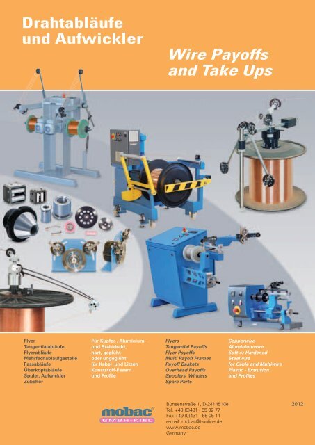
Flyer<br />
Tangentialabläufe<br />
Flyerabläufe<br />
Mehrfachablaufgestelle<br />
Fassabläufe<br />
Überkopfabläufe<br />
Spuler, Aufwickler<br />
Zubehör<br />
Für Kupfer-, Aluminium-<br />
und Stahldraht,<br />
hart, geglüht<br />
oder ungeglüht<br />
für Kabel und Litzen<br />
Kunststoff-Fasern<br />
und Profile<br />
Flyers<br />
Tangential Payoffs<br />
Flyer Payoffs<br />
Multi Payoff Frames<br />
Payoff Baskets<br />
Overhead Payoffs<br />
Spoolers, Winders<br />
Spare Parts<br />
Bunsenstraße 1, D-24145 Kiel<br />
Tel. +49 (0)431 - 65 02 77<br />
Fax +49 (0)431 - 65 05 11<br />
e-mail: mobac@t-online.de<br />
www.mobac.de<br />
Germany<br />
Copperwire<br />
Aluminiumwire<br />
Soft or Hardened<br />
Steelwire<br />
for Cable and Multiwire<br />
Plastic - Extrusion<br />
and Profiles<br />
2012
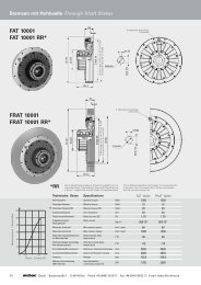
Bremsen an Abwickelflyern Brakes on Payoff Flyers<br />
... sanfte Drehmomente und feinfühlige Zugregelung<br />
Gehäuse<br />
Al-housing<br />
Rollreibungsbremse<br />
Bei den kleineren Typen, wie F20<br />
werden im Standardfall<br />
Rollreibungsbremsen verwendet,<br />
welche feinfühlig durch Andruck-<br />
Schraubkraft auf das benötigte<br />
Drehmoment eingestellt werden.<br />
Rolling Friction Brake<br />
There are used rolling friction brakes<br />
with the smaller types such as F20.<br />
These brakes are sensibly adjustable<br />
by screw pressure.<br />
Reibbremsbelag<br />
Einsteckzapfenverriegelung<br />
Bremsdruck<br />
braking<br />
pressure<br />
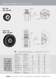
Fliehkraftbremse<br />
Patent von mobac angemeldet.<br />
Die gezeigte Fliehkraftbremse wird zur<br />
Bremsregelung vornehmlich höherer<br />
Drahtzüge im Stahlbereich eingesetzt.<br />
Sie lüftet sich zunehmend mit ansteigender<br />
Drehzahl und wirkt dadurch<br />
bremsregelnd über den Durchmesserbereich<br />
beim Anlauf und im Schnellstopp.<br />
Braking Control by Centrifugal Force<br />
patent applications by mobac.<br />
The centrifugal controlled brake is used<br />
to control high wire tension of mostly<br />
steel wire over the bobbin diameter. The<br />
brake is lifting more with increasing rpm<br />
and by that is controlling the tension<br />
also from start and prevents backlash at<br />
quickstop.<br />
friction<br />
brake<br />
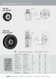
Bremskombination<br />
Rollreibungsbremse /<br />
Friktionsbremse<br />
Bei den Flyern der Typenreihe<br />
F24/26 findet ein kombiniertes<br />
Bremssystem Verwendung.<br />
Hier ist ein Rollreibungssystem<br />
zur Feineinstellung<br />
des Bremsmomentes<br />
eingebaut und zum Anderen<br />
ein normales Friktionsbremssystem<br />
zur Verstellung der<br />
Bremsung im groben Bereich.<br />
Combined<br />
Rolling Friction Brake /<br />
Friction Brake<br />
A combined braking system is<br />
used with Flyers of types<br />
F24/26. On the one hand, the<br />
rolling friction system is build<br />
in for the fine adjustment of<br />
the braking torque on the<br />
other hand a real friction brake<br />
is used for high torque<br />
braking. The advantage of this<br />
combined braking system is<br />
that there is a possibility of an<br />
accurate adjustment of torque<br />
on top of mentioned friction<br />
brake .<br />
Hysteresebremse<br />
Hysteresebremsen arbeiten<br />
verschleißfrei sowie<br />
geräuschlos und sind deshalb<br />
sehr geeignet für die<br />
Anwendung am Abwickelflyer.<br />
Das eingestellte<br />
Drehmoment ist unabhängig<br />
von Drehzahlen.<br />
Hysteresis Brake<br />
Hysteresis brakes are working<br />
noiseless and without any<br />
wear. Allthough not a<br />
lowprice solution they are<br />
very suitable for the use in<br />
payoff flyers, as the torque is<br />
smooth and independent<br />
from rpm variation.<br />
Magnetpulverbremse<br />
Auf Anfrage wird eine Magnetpulverbremse<br />
eingebaut. Mit<br />
dieser Einheit ist es möglich über<br />
Potentiometer und Netzteil den<br />
Zug während des Laufs zu<br />
verstellen und bei Drahtriss<br />
ebenfalls einen Schnellstopp des<br />
Flyers durch Vollbremsung zu<br />
schalten.<br />
Magnetic Particle Brake<br />
Some payoff flyers are specially<br />
equipped with magnetic particle<br />
brakes. With this brake it is<br />
possible to control the wire<br />
tension by potentiometer and<br />
power supply while the Flyer is<br />
operating as well as a fast stop<br />
of the flyer in case of wire break<br />
by finish of wire run.<br />
... smooth torque and sensible tension control<br />
®<br />
2 <strong>GmbH</strong> · Bunsenstraße 1 · D-24145 Kiel · Phone +49 (0)431-65 02 77 · Fax +49 (0)431-65 05 11 · E-mail: mobac@t-online.de<br />
rolling<br />
friction<br />
brake<br />
Unsere Drahtzugangaben sind<br />
auch abhängig von Drehzahlen.<br />
Wire tensions dependable on rpm<br />
figures.<br />
FeststellschraubeEinsteckzapfenverriegelung<br />
Bremsverstellungshebel<br />
magnetic<br />
powder<br />
brake
Inhalt Summery<br />
Tabellen für Drahtzugwerte<br />
Schedule for<br />
Wire Tension Values<br />
................................................ 4<br />
Einsteckflyer<br />
Flyers to put in Bobbin Hole<br />
................................................ 5<br />
Schnelle Flyerabläufe<br />
High Speed Flyer Payoffs<br />
.................................................9<br />
Flyer mit Einzelablaufgestell<br />
Single Flyer Payoff Frames<br />
.............................................11<br />
Flyer für Gestellbefestigung<br />
Flyers for use in Frame<br />
.............................................16<br />
®<br />
Mehrfachablaufgestelle<br />
Multi Payoff Frames<br />
Endlosabläufe<br />
Continuous Payoffs<br />
Umschlingungs-<br />
Hysteresebremsen<br />
Wind Around<br />
Hysteresis Brakes<br />
19<br />
.............................................24<br />
Flyer mit Zugregelung<br />
Flyers with Tension Control<br />
.............................................26<br />
Ersatzteilliste<br />
für Abwickelflyer<br />
Spare Part List<br />
for Flyer Payoffs<br />
27<br />
.............................................38<br />
Tänzerspeicher<br />
Dancer Accumulators<br />
.............................................40<br />
Kronenstockabläufe<br />
Coil Payoffs<br />
.............................................41<br />
Fassabläufe<br />
Payoff Baskets<br />
.............................................43<br />
Tangentialabläufe<br />
Tangential Payoffs<br />
.............................................44<br />
Angetriebene Tangentialabläufe<br />
Driven Tangential Payoffs<br />
.............................................49<br />
Spuler/Aufwickler<br />
Spoolers/Winders<br />
.............................................52<br />
Umspulanlagen<br />
Rewinding Units<br />
.............................................59<br />
Schnellspannsysteme<br />
Clamping Systems<br />
.............................................60<br />
Zubehör<br />
Spare Parts<br />
.............................................61<br />
Rollenkreuze<br />
Cross-rollers<br />
.............................................65<br />
Bestellbezeichnung für<br />
Abwickelflyer<br />
Order Specifications<br />
of Payoff Flyers<br />
.............................................67<br />
<strong>GmbH</strong> · Bunsenstraße 1 · D-24145 Kiel · Phone +49 (0)431-65 02 77 · Fax +49 (0)431-65 05 11 · E-mail: mobac@t-online.de<br />
3
Tabellen für Drahtzugwerte Schedule for wire tension values<br />
Empfohlene Drahtzugkräfte mit Cu-Drähten<br />
Recommended wire tension values with copper wires<br />
Durchmesser<br />
wire dia<br />
AWG<br />
wire<br />
gauge<br />
Zugspannung<br />
tensile<br />
stress<br />
zulässige<br />
Zugkraft<br />
bei weichem<br />
Draht,<br />
nach der<br />
Glühe<br />
tensile force<br />
for soft wire<br />
after<br />
annealer<br />
zulässige<br />
Zugkraft<br />
bei hartem<br />
Draht,<br />
ohne Glühe<br />
tensile force<br />
for hard<br />
wire<br />
entering<br />
annealer<br />
zulässige<br />
Zugkraft<br />
mit<br />
statischem<br />
Wickler<br />
tensile force<br />
with static<br />
coiler<br />
(mm)<br />
(N/mm<br />
0,02 157,0 0,0345 0,0592 0,0247<br />
0,04 135,0 0,1187 0,2035 0,0848<br />
0,06 116,0 0,2295 0,3934 0,1639<br />
0,08 104,0 0,3658 0,6270 0,2613<br />
0,10 98,0 0,5385 0,9232 0,3847<br />
0,12 94,0 0,7438 1,2751 0,5313<br />
0,14 0,91 0,9801 1,6802 0,7001<br />
0,16 88,5 1,2450 2,1342 0,8893<br />
0,18 87,0 1,5489 2,6553 1,1064<br />
0,20 50 85,0 1,8683 3,2028 1,3345<br />
0,22 49 83,5 2,2208 5,8070 1,5863<br />
0,23 48 83,0 2,4127 4,1361 1,7234<br />
0,24 47 82,0 2,5954 4,4493 1,8539<br />
0,25 46 81,5 2,7991 4,7983 1,9993<br />
0,26 45 81,0 3,0089 5,1580 2,1492<br />
0,27 44 80,5 3,2248 5,5281 2,3034<br />
0,28 43 80,0 2,4465 5,9082 2,4618<br />
0,30 78,5 3,8822 6,6552 2,7730<br />
0,31 42 78,0 4,1190 7,0611 2,9421<br />
0,32 77,5 4,3608 7,4757 3,1149<br />
0,34 41 76,5 4,8595 8,3305 3,4711<br />
0,35 40 76,0 5,1159 8,7700 3,6542<br />
0,36 75,5 5,3768 9,2173 3,8406<br />
0,37 39 75,0 5,6420 9,6720 4,0300<br />
0,38 74,5 5,9114 10,1339 4,2225<br />
0,40 38 73,5 6,4621 11,0797 4,6158<br />
0,42 37 72,5 7,0276 12,0473 5,0197<br />
0,43 72,0 7,3154 12,5407 5,2253<br />
0,45 36 71,5 7,9561 13,6390 5,6829<br />
0,47 70,5 8,5577 14,6702 6,1126<br />
0,50 35 69,5 9,5476 16,3673 6,8197<br />
0,55 34 68,0 11,3032 19,3770 8,0737<br />
2 ) (N)<br />
(N)<br />
(N)<br />
Richtwerte für die<br />
Rückhaltekräfte an Abläufen<br />
vor einer Verseilmaschine<br />
Guidance values for<br />
backtension at the pay off to<br />
enter a bunching machine<br />
Rückhaltekraft/Backtension<br />
F(N)<br />
70<br />
60<br />
50<br />
40<br />
30<br />
20<br />
10<br />
Durchmesser<br />
wire dia<br />
0,60 33 66,5 13,1550 22,5515 9,3965<br />
0,65 32 64,5 14,9764 25,6707 10,6962<br />
0,70 31 62,5 16,8285 28,8444 12,0203<br />
0,75 30 50,0 18,55 31,79 13,25<br />
0,80 29 58,0 20,40 34,97 14,57<br />
0,85 28 56 22,23 38,11 15,88<br />
0,90 27 54,0 24,04 41,20 17,17<br />
0,95 26 51,5 25,54 43,78 18,24<br />
1,00 25 49,0 26,93 46,16 19,23<br />
1,10 45,0 29,92 51,29 21,37<br />
1,20 42,5 33,63 57,65 24,02<br />
1,30 40,5 37,51 64,48 26,86<br />
1,40 39,0 42,00 72,01 30,00<br />
1,50 24 37,0 45,75 78,42 32,68<br />
1,60 23 33,5 49,94 85,61 35,67<br />
1,70 22 34,0 53,99 92,56 38,57<br />
1,80 21 32,5 57,68 99,19 41,33<br />
1,90 20 32,0 63,48 108,82 45,34<br />
2,00 19 31,5 69,24 118,69 49,64<br />
2,20 18 31,0 82,45 141,34 58,89<br />
2,30 30,0 87,21 149,50 62,29<br />
2,40 17 29,0 91,79 157,35 65,56<br />
2,50 16 28,5 97,88 167,79 69,91<br />
2,60 15 28,0 104,01 178,30 74,29<br />
2,70 27,5 110,16 188,85 78,69<br />
2,80 14 27,0 116,32 199,40 83,08<br />
2,90 26,5 122,46 209,94 87,47<br />
3,00 13 26,0 128,58 220,43 91,85<br />
3,20 25,0 140,67 241,15 100,48<br />
3,80 10 24,0 190,43 326,45 136,02<br />
4,00 9 23,0 202,22 346,65 144,44<br />
4,20 8 22,0 213,25 365,75 152,32<br />
®<br />
4 <strong>GmbH</strong> · Bunsenstraße 1 · D-24145 Kiel · Phone +49 (0)431-65 02 77 · Fax +49 (0)431-65 05 11 · E-mail: mobac@t-online.de<br />
(mm)<br />
AWG<br />
wire<br />
gauge<br />
48 N/mm 2<br />
Zugspannung<br />
tensile<br />
stress<br />
(N/mm 2 )<br />
40 N/mm 2<br />
zulässige<br />
Zugkraft<br />
bei weichem<br />
Draht,<br />
nach der<br />
Glühe<br />
tensile force<br />
for soft wire<br />
after<br />
annealer<br />
(N)<br />
zulässige<br />
Zugkraft<br />
bei hartem<br />
Draht,<br />
ohne Glühe<br />
tensile force<br />
for hard<br />
wire<br />
entering<br />
annealer<br />
(N)<br />
6000 5600<br />
32 N/mm 2<br />
20 N/mm 2<br />
zulässige<br />
Zugkraft<br />
mit<br />
statischem<br />
Wickler<br />
tensile force<br />
with static<br />
coiler<br />
0 0,25 0,5 0,75 1,0 1,25 1,5 1,75 2,0 A (mm2 )<br />
Drahtquerschnitt/Wire cross section<br />
(N)<br />
5000<br />
4000<br />
Schläge/min<br />
Twists/min
Einsteckflyer und Gestellflyer Flyers for Bobbin Hole and for Mounting in Frame<br />
F22E-N560/630K<br />
Typ/Type<br />
1. F22E-N560/630 K<br />
2. F22E-N560/630Y<br />
3. F22E-2M560/630YK<br />
4. F22E-2M560/630PK<br />
Typ<br />
Type<br />
F22E-N560/630K<br />
F22E-N560/630YK<br />
F22E-2M560/630YK<br />
F22E-2M560/630PK<br />
®<br />
Flansch Ø<br />
Flange Ø<br />
560 - 630 mm<br />
560 - 630 mm<br />
560 - 630 mm<br />
560 - 630 mm<br />
Ausführung<br />
Ø Cu-, Al-Draht<br />
Ø Cu, Al wire<br />
0,1 - 0,7 mm<br />
0,1 - 0,7 mm<br />
0,2 - 0,8 mm<br />
0,2 - 0,8 mm<br />
Gezeigt ist die<br />
Type F22E-2M560/630YK<br />
mit universell verstellbarer<br />
Umlenkwalze<br />
The picture shows the unit<br />
F22E-2M560/630YK<br />
with universal adjustable<br />
cylindric roller<br />
Abwickelflyer zur Befestigung im Spulenkernloch<br />
in Normalausführung, d.h. ohne<br />
Umlenkwalze aber mit Drahtzugkompensator<br />
und mit Friktionsbremse.<br />
Rollen Ø 45 mm, Typ A 502080<br />
Abwickelflyer wie unter 1, jedoch ausgerüstet<br />
mit Hysteresebremse Typ 523<br />
Abwickelflyer wie unter 1, jedoch ausgerüstet<br />
mit zylindrischer Umlenkwalze und<br />
Hysteresebremse Typ 523<br />
Abwickelflyer wie unter 1, jedoch ausgerüstet<br />
mit zylindrischer Umlenkwalze und<br />
Magnetpulverbremse Typ FRAT 50<br />
Ø Stahldraht hart<br />
Ø Steelwire hard<br />
max. 0,4 mm<br />
max. 0,4 mm<br />
max. 0,5 mm<br />
max. 0,5 mm<br />
Ø Stahldraht weich<br />
Ø Steelwire soft<br />
max. 0,6 mm<br />
max. 0,6 mm<br />
max. 0,7 mm<br />
max. 0,7 mm<br />
F22E-2M560/630YK<br />
F22E-2M560/630PK<br />
Execution<br />
Flyer unit to put in bobbin hole in simplest<br />
execution, i.e. without cylindric roller but with<br />
tension compensator and friction brake<br />
Pulleys Ø 45 mm, Type A 502080<br />
Flyer unit as under 1, but equipped with<br />
hysteresis brake type 523<br />
Flyer unit as under 1, but equipped with<br />
cylindric roller and hysteresis brake type 523<br />
Flyer unit as under 1, but equipped with<br />
cylindric roller and magnetic powder brake<br />
Type FRAT 50<br />
Drahtgeschwindigkeit<br />
Wire speed<br />
max. 200 m/min<br />
max. 200 m/min<br />
max. 200 m/min<br />
max. 200 m/min<br />
<strong>GmbH</strong> · Bunsenstraße 1 · D-24145 Kiel · Phone +49 (0)431-65 02 77 · Fax +49 (0)431-65 05 11 · E-mail: mobac@t-online.de<br />
Drahtzug<br />
Wire tension<br />
3 - 11 N<br />
3 - 8 N<br />
4 - 13 N<br />
4 - 17 N<br />
5
Einsteckflyer und Gestellflyer Flyers for Bobbin Hole and for Mounting in Frame<br />
F44E-N560/630Y<br />
F46E-N630/800P<br />
Abwickelflyer mit Frktionsbremse auf Anfrage.<br />
Flyer units with friction brake on request.<br />
Typ/Type<br />
1. F44E-N560/630Y<br />
2. F46E-N630/800P<br />
3. F44E-M560/630Y<br />
4. F46E-M630/800P<br />
Typ<br />
Type<br />
F44E-N560/630Y<br />
F46E-N630/800P<br />
F44E-M560/630Y<br />
F46E-M630/800P<br />
Flansch Ø<br />
Flange Ø<br />
560 - 630 mm<br />
630 - 800 mm<br />
560 - 630 mm<br />
630 - 800 mm<br />
Ausführung<br />
Ø Cu-, Al-Draht<br />
Ø Cu, Al wire<br />
0,4 - 1,0 mm<br />
0,6 - 1,9 mm<br />
0,4 - 1,0 mm<br />
0,6 - 1,9 mm<br />
gezeigt ist die Ausführung<br />
F44E-N560/630Y<br />
mit Edelstahlrollen Typ RE 80<br />
shown is the execution<br />
F44E-N560/630Y<br />
with stainless steel rolls<br />
Type RE 80<br />
Abwickelflyer zum Einstecken in das Spulenkernloch in<br />
Normalausführung, dh. ohne Umlenkwalze, aber mit<br />
Drahtzugkompensator und Permanentmagnet-Hysteresebremse<br />
Typ 610. Rollen Ø 80 mm, Typ A 701050 Kunststoff/<br />
Ceramic oder Edelstahl Typ RE 80<br />
Abwickelflyer zum Einstecken wie unter 1, jedoch ausgeführt<br />
für Spulengrößen Ø 630 mm bis Ø 800 mm und ausgerüstet<br />
mit Magnetpulverbremse Typ FRAT 350. RollenØ 98 mm,<br />
Typ SP 09880 Kunststoff/Ceramic oder Edelstahl Typ RE 98<br />
Abwickelflyer zum Einstecken in das Spulenkernloch in<br />
Ausführung mit zylindrischer Umlenkwalze und Drahtzugkompensator<br />
Permanentmagnet-Hysteresebremse Typ 610.<br />
Rollen Ø 80 mm, Typ A 701050 Kunststoff/Ceramic oder<br />
Edelstahl Typ RE 80<br />
Abwickelflyer wie unter 3, jedoch für Spulen Ø 630 mm<br />
bis Ø 800 mm.<br />
Ausgerüstet mit mit Magnetpulverbremse Typ FRAT 350.<br />
Rollen Typ SP 09880 aus Kunststoff/Keramik Ø 98 mm oder<br />
Edelstahl Typ RE 98<br />
Ø Stahldraht hart<br />
Ø Steelwire hard<br />
max. 0,6 mm<br />
max. 0,8 mm<br />
max. 0,6 mm<br />
max. 0,8 mm<br />
F44E-M560/630Y<br />
F46E-M630/800P<br />
gezeigt ist die Ausführung<br />
F44E-M560/630Y<br />
mit Edelstahlrollen Typ RE 80<br />
shown is the execution<br />
F44E-M560/630Y<br />
with stainless steel rolls Type RE 80<br />
Ø Stahldraht weich<br />
Ø Steelwire soft<br />
max. 0,9 mm<br />
max. 1,5 mm<br />
max. 0,9 mm<br />
max. 1,5 mm<br />
Execution<br />
Flyer unit to put in bobbin hole in standard execution, i.e. without<br />
cylindric roller but with tension compensator and permanent<br />
magnetic hysteresis brake type 610 .<br />
Pulleys Ø 80 mm, type A 701050 plastic/ceramic<br />
or type RE 80 stainless steel<br />
Flyer unit to put in bobbin hole as discribed under pos. 1, but built<br />
to be used with spools Ø 630 mm to Ø 800 mm and equipped<br />
with magnetic particle brake type FRAT 350. Pulleys Ø98 mm,<br />
type SP 09880 plastic/ceramic or type RE 98 stainless steel.<br />
Flyer unit to put in bobbin hole in execution with cylindric roller,<br />
tension compensator and permanent magnetic hysteresis brake<br />
type 610<br />
Pulleys Ø 80 mm, type A 701050 plastic/ceramic or type RE 80<br />
stainless steel<br />
Flyer unit to put in bobbin hole as discribed under pos. 3, but built<br />
to be used with spools Ø 630 mm to Ø 800 mm and equipped<br />
with magnetic particle brake type FRAT 350.<br />
Pulleys Ø 98 mm, type SP 09880 plastic/ceramic or type RE 98<br />
stainless steel<br />
Drahtgeschwindigkeit<br />
Wire speed<br />
max. 200 m/min<br />
max. 250 m/min<br />
max. 200 m/min<br />
max. 250 m/min<br />
Drahtzug<br />
Wire tension<br />
min. 4 N, max. 28 N<br />
min. 4 N, max. 48 N<br />
min. 4 N, max. 28 N<br />
min. 4 N, max. 48 N<br />
®<br />
6 <strong>GmbH</strong> · Bunsenstraße 1 · D-24145 Kiel · Phone +49 (0)431-65 02 77 · Fax +49 (0)431-65 05 11 · E-mail: mobac@t-online.de
Einsteckflyer und Gestellflyer Flyers for Bobbin Hole and for Mounting in Frame<br />
Typenreihe / Series F26<br />
F26E-2M630/800YK F26E-2M630/800PK<br />
Flansch Ø<br />
Flange Ø<br />
560 - 800 mm<br />
Drahtgeschwindigkeit<br />
Wire speed<br />
max. 200 m/min.<br />
®<br />
Vielfachdraht<br />
Multiwire<br />
max. 8 x 0,65 mm<br />
Drahtzug<br />
wire tension<br />
für Spulen/for spools Ø 800 mm<br />
Cu-, Al-Draht Ø<br />
Cu, Al wire Ø<br />
0,6 - 1,9 mm<br />
Hysteresebremse<br />
Hysteresis brake<br />
4 - 28 N<br />
Mögliche Ausführungen / Possible executions<br />
Typ/Type<br />
Beschreibung<br />
F26 E-2M 560/630 K Ausführung mit Reibbelagbremse, jedoch PTFE-Bremsbelag,<br />
höhere Bremsmomente, einfacher Aufbau. Ausgleich der perio-<br />
F26 E-2M 630/800 K dischen Drahtzugschwankungen. Preisgünstigste Ausführung<br />
F26 E-2M 560/630 YK Ausführung mit Hysteresebremse und Drahtzugkompensator,<br />
weicher Anlauf und Stop. Ausgleich der periodischen Drahtzug-<br />
F26 E-2M 630/800 YK schwankungen, 2 seitliche Arme für universelle Drehrichtung<br />
F26 E-2M 560/630 PK Ausführung mit Magnetpulverbremse und Drahtzugkompensator,<br />
d.h. Zugeinstellung auch während des Betriebs. Ausgleich der<br />
F26 E-2M 630/800 PK periodischen Zugschwankungen.<br />
Ø der Einsteckzapfen (Spulenbohrung mm)<br />
Ø of bobbin hole (mm)<br />
ausgerüstet mit Stahlrollen Ø 98 mm<br />
equipped with steel pulleys dia 98 mm<br />
für universelle Drehrichtung<br />
for both turning directions<br />
A B C D E F G<br />
50 56 80 100 125 127 250<br />
Bezeichnungs-Beispiel eines Einsteckflyers F26 mit Umlenkwalze,<br />
Drahtzugkompensator und Hysteresebremse für Spulengröße 630 mm.<br />
Länge der Umlenkwalze 380 mm,<br />
Durchmesser des verriegelbaren Einsteckzapfens 127 mm:<br />
F26 E-2M 630YK Ausführung F4<br />
Stahldraht hart Ø<br />
Steelwire hard Ø<br />
max. 0,8 mm<br />
Reibbelagbremse<br />
Friction brake<br />
4 - 36 N<br />
Description<br />
Stahldraht weich Ø<br />
Steelwire soft Ø<br />
max. 1,5 mm<br />
<strong>GmbH</strong> · Bunsenstraße 1 · D-24145 Kiel · Phone +49 (0)431-65 02 77 · Fax +49 (0)431-65 05 11 · E-mail: mobac@t-online.de<br />
stromgeregeltes<br />
Netzversorgungsteil<br />
power supply unit<br />
- current controlled<br />
Magnetpulverbremse<br />
Magnetic particle brake<br />
6 - 49 N<br />
Flyer unit with friction brake (PTFE) and tension compensator.<br />
Simplest execution, lowest price, unit will compensate periodic<br />
tension variations<br />
Flyer unit with hysteresis brake and tension compensator.<br />
Soft start and stop, no backlash, unit will compensate periodic tension<br />
variations, and two sideaway arms for both turning direction.<br />
Execution with magnetic particle brake and tension compensator.<br />
I.i. tension adjustment possible during operaration.<br />
Unit will compensate periodic tension variations<br />
Länge der Umlenkwalze (mm)<br />
Length of cylindric roller (mm)<br />
1 2 3 4 5 6<br />
260 335 295 380 430 480<br />
Example of specification for a flyer to put in bobbin hole with cylindric<br />
roller, tension compensator and hysteresis brake for bobbin size 630 mm.<br />
Length of cylindric roller 380 mm,<br />
dia of eccentric clamping equipment 127 mm:<br />
F26 E-2M 630YK Execution F4<br />
7
Einsteckflyer Flyers for Bobbin Hole<br />
F30E-N800/1250YK<br />
Ausführung C/Execution C<br />
Flansch Ø<br />
Flange Ø<br />
800 - 1250 mm<br />
Vielfachdraht<br />
Multiwire<br />
max. 24 x 0,65 mm<br />
Cu-, Al-Draht Ø<br />
Cu, Al wire Ø<br />
1,0 - 3,0 mm<br />
Stahldraht hart Ø<br />
Steelwire hard Ø<br />
max. 1,8 mm<br />
Stahldraht weich Ø<br />
Steelwire soft Ø<br />
max. 2,2 mm<br />
Mögliche Ausführungen / Possible executions<br />
Typ/Type<br />
Beschreibung<br />
F30 E-N800/1000 Y Ausführung mit Hysteresebremse,<br />
dadurch weicher Anlauf und Stop<br />
F30 E-N1000/1250 Y Rückzug auch im Stillstand<br />
F30 E-N800/1000 YK Ausführung mit Hysteresebremse und Drahtzugkompensator, dadurch<br />
weicher Anlauf und Stop. Rückzug auch im Stillstand. Ausgleich der<br />
F30 E-N1000/1250 YK periodischen Drahtzugschwankungen<br />
F30 E-2M800/1000 YK Ausführung mit Umlenkwalze, Hysteresebremse und Drahtzugkompensator,<br />
dadurch weicher Anlauf und Stop. Rückzug auch im Stillstand. Ausgleich der<br />
F30 E-2M1000/1250 YK periodischen Drahtzugschwankungen. Verwendbar für beide Drehrichtungen<br />
Ø der Einsteckzapfen (Spulenbohrung mm)<br />
Ø of bobbin hole (mm)<br />
A B C D E F G<br />
51 56 80 82 125 127 250<br />
Bezeichnungs-Beispiel eines Einsteckflyers F30 mit Umlenkwalze<br />
Drahtzugkompensator und Hysteresebremse für Spulengröße<br />
1000 mm<br />
Durchmesser des verriegelbaren Einsteckzapfens 80 mm:<br />
F30 E-2M 1000YK Ausführung C<br />
F30E-2M1250Y Ausführung C/Execution C<br />
mit universell verstellbarer<br />
Umlenkwalze<br />
with universal adjustable<br />
cylindric roller<br />
ausgerüstet wahlweise mit Al-Rollen keramikbeschichtet Typ RA166-C oder Stahlrollen Typ RS166<br />
equipped alternatively with Al pulleys ceramic coated type RA166-C or steel pulleys type RS166<br />
Drahtgeschwindigkeit<br />
Wire speed<br />
max. 300 m/min.<br />
Bei Ausführung mit Reibbelagbremse<br />
For execution with friction plate brake<br />
Description<br />
Drahtzug<br />
Wire tension<br />
min. 10 N, max. 70 N<br />
min. 7 N, max. 90 N<br />
Flyer unit with hysteresis brake<br />
for soft start and stop<br />
Backtension also at unit in standstill position<br />
Flyer unit with hysteresis brake and tension compensator.<br />
Soft start and stop, no backlash,<br />
unit will compensate periodic tension variations<br />
Flyer unit with cylindric roller, hysteresis brake and tension compensator.<br />
Soft start and stop, no backlash, unit will compensate periodic<br />
tension variations.To be used for both sens of turning directions<br />
Example of specification for a flyer F30 to put in bobbin hole with<br />
cylindric roller, tension compensator and hysteresis brake for bobbin<br />
size 1000 mm<br />
dia of eccentric clamping equipment 80 mm:<br />
F30 E-2M 1000YK Execution C<br />
®<br />
8 <strong>GmbH</strong> · Bunsenstraße 1 · D-24145 Kiel · Phone +49 (0)431-65 02 77 · Fax +49 (0)431-65 05 11 · E-mail: mobac@t-online.de
Schnelle Flyerabläufe High Speed Flyer Payoffs<br />
F8G-2N80/100YH<br />
F8G-2N100/150YH<br />
Abwickelflyer zur Gestellbefestigung<br />
mit Spulenaufnahme, Arretierung der Spule durch FastLock-Einheit.<br />
Feinfühlige Züge durch Hysteresebremsverstellung,<br />
für Spulen Ø 80 - 150 mm<br />
Flyer Payoff for frame mounting<br />
with center axis to carry the spool, positioning by FastLock unit.<br />
Sensible tension by hysteresis<br />
brake adjustment,<br />
for spools Ø 80 - 150 mm<br />
Typ<br />
Type<br />
F8G-2N80/150YH<br />
F8G-2N200/500YH<br />
F20G-Gfk350/500<br />
F21G-Gfk560/630<br />
Flansch Ø<br />
Flange Ø<br />
350 - 630 mm<br />
®<br />
Flansch Ø<br />
Flange Ø<br />
80 - 150 mm<br />
200 - 500 mm<br />
Vielfachdraht<br />
Multiwire<br />
max. 8 x 0,35 mm<br />
Ø Cu-, Al-Draht<br />
Dia. Cu, Al wire<br />
0,04 - 0,2 mm<br />
0,08 - 0,5 mm<br />
bis/to<br />
800 m/min<br />
Abwickelflyer zur Gestellbefestigung mit Glasfaserarm<br />
für Spulen Ø 350 - 630 mm<br />
Abwickelflyer für hohe Ablaufgeschwindigkeiten, hauptsächlich<br />
verwendet im Cu- und Al-Bereich zum Umspulen, aber auch vor<br />
Verseilmaschinen. Die Einheit zeichnet sich auch durch sehr<br />
ruhigen Lauf aus.<br />
Flyer Payoff for frame mounting with glass fibre arm<br />
for spools Ø 350 - 630 mm<br />
Payoff Flyer for high speed mainly used in copper and aluminium<br />
applications for rewinding and also to feed bunching machines. The<br />
unit enables also very smooth operation.<br />
Ø Cu-, Al-Draht<br />
Dia. Cu, Al wire<br />
0,15 - 0,9 mm<br />
Ø Stahldraht hart<br />
Dia. Steelwire hard<br />
max. 0,4 mm<br />
F8G-2N200/250YH<br />
F8G-2N355/500YH<br />
Flyerablauf für hohe Ablaufgeschwindigkeiten.<br />
Arretierung der Spule durch eine FastLock-Einheit<br />
oder eine Easylock-Einheit.<br />
Justierung der Züge durch Hysteresebremsverstellung<br />
Flyer Payoff for high speed. The spool is kept in<br />
position by a Fastlock or an Easylock unit.<br />
Adjustment of tension by controlling the hysteresis<br />
brake<br />
Ø Stahldraht hart<br />
Dia. Steelwire hard<br />
max. 0,1 mm<br />
max. 0,15 mm<br />
Ø Stahldraht weich<br />
Dia. Steelwire soft<br />
max. 0,6 mm<br />
Drahtgeschwindigkeit<br />
Wire speed<br />
max. 800 m/min<br />
max. <strong>900</strong> m/min<br />
F20G-Gfk240/630T<br />
Drahtgeschwindigkeit<br />
Wire speed<br />
max. 800 m/min<br />
<strong>GmbH</strong> · Bunsenstraße 1 · D-24145 Kiel · Phone +49 (0)431-65 02 77 · Fax +49 (0)431-65 05 11 · E-mail: mobac@t-online.de<br />
Drahtzug<br />
Wire tension<br />
min. 1 N, max. 4 N<br />
min. 2 N, max. 12 N<br />
Drahtzug<br />
Wire tension<br />
min.1 N, max. 6 N<br />
9
Schnelle Flyerabläufe High Speed Flyer Payoffs<br />
F20E-Gfk560/630 F23E-Gf630/800/800Y<br />
Typ<br />
Type<br />
F20E-Gfk560/630<br />
F21E-Gfk630/710<br />
F23E-Gfk800Y<br />
Flansch Ø<br />
Flange Ø<br />
560 - 630 mm<br />
630 - 710 mm<br />
800 mm<br />
F20G-Gfk560/630HT<br />
Vielfachdraht<br />
Multiwire<br />
max. 8 x 0,25 mm<br />
max. 8 x 0,35 mm<br />
max. 8 x 0,65 mm<br />
Abwickelflyer mit Glasfaserarm im Ablaufgestell<br />
mit Tänzerspeicher<br />
für Spulen Ø 560 und 630 mm<br />
Flyer Payoff with glass fibre arm, mounted in<br />
frame, with dancer accumulator,<br />
for spools Ø 560 - 630 mm<br />
Diese Einheiten werden vorwiegend<br />
für hohe Geschwindigkeiten beim<br />
Umspulen von Kupfer- und<br />
Aluminiumdrähten eingesetzt sowie<br />
zur Zuführung in Verseilmaschinen.<br />
Sie ermöglichen außerdem einen<br />
außerst störungsarmen Betrieb.<br />
Achtung: Verwendung nur mit passendem<br />
Schutzgitter kundenseitig.<br />
Auf Anfrage bietet mobac geeignete<br />
Schutzgitter an.<br />
These units are mainly used for high<br />
speed in copper and aluminum<br />
applications for rewinding and also to<br />
feed bunching machines.<br />
These types also enables very smooth<br />
operation.<br />
Attention: These units should only be<br />
used with adequate shielding that the<br />
customer should care for.<br />
A suitable shielding can be quoted by<br />
mobac on request.<br />
Ø Cu-, Al-Draht<br />
Ø Cu, Al wire<br />
0,15 - 0,6 mm<br />
0,20 - 0,8 mm<br />
0,30 - 1,0 mm<br />
Ø Stahldraht hart<br />
Ø Steelwire hard<br />
max. 0,3 mm<br />
max. 0,4 mm<br />
max. 0,5 mm<br />
F21G-Gfk630/710YHT<br />
Ø Stahldraht weich<br />
Ø Steelwire soft<br />
max. 0,5 mm<br />
max. 0,6 mm<br />
max. 0,7 mm<br />
Abwickelflyer wie links, jedoch mit Hysteresebremse<br />
für Spulen Ø 630 und 710 mm<br />
Flyer Payoff as shown left, but with hysteresis<br />
brake, for spools Ø 630 - 710 mm<br />
Drahtgeschwindigkeit<br />
Wire speed<br />
max. 800 m/min<br />
max. 800 m/min<br />
max. 800 m/min<br />
F23G-Gfk800HT<br />
Drahtzug<br />
Wire tension<br />
min. 1 N, max 6 N<br />
min. 2 N, max 11 N<br />
min. 3 N, max 15 N<br />
Abwickelflyer wie links außen jedoch mit<br />
Rollenkopf für Ø 80 mm Umlenkrolle,<br />
für Spulen Ø 800 mm<br />
Flyer Payoff as shown top left but with<br />
rollerheads for Ø 80 mm pulleys,<br />
for spools Ø 800 mm<br />
Flyerablauf zum Abziehen von<br />
Einzeldraht und Vielfachdraht mit<br />
hoher Geschwindigkeit (max. 800 m/<br />
min). Anwendung in der Hauptsache<br />
beim Umspulen (z.B. Aufwickeln von<br />
Flechtspulen). Dieser Ablauf zeichnet<br />
sich durch sehr ruhigen Lauf aus.<br />
Flyer Payoff for use of singlewire and<br />
multiwire with high speed (max.<br />
800 m/min). Purpose in most cases is<br />
rewinding (for example braiding<br />
spools).<br />
This unit offers very calm payoff.<br />
®<br />
10 <strong>GmbH</strong> · Bunsenstraße 1 · D-24145 Kiel · Phone +49 (0)431-65 02 77 · Fax +49 (0)431-65 05 11 · E-mail: mobac@t-online.de
Flyer mit Einzelablaufgestell Single Flyer Payoff Frames<br />
F10G-O80/200HT F15G-N100/300PHT<br />
Abwickelflyer mit Ablaufgestell und Tänzerspeicher<br />
für Spulen Ø 80 - 200 mm. Flyertyp F10G mit Ösen<br />
für Drahtstärke Cu Ø 0,05 - 0,3 mm<br />
Flyer Payoff mounted<br />
in frame<br />
with dancer accumulator<br />
for spools Ø 80 - 200 mm.<br />
Flyer type F10G with eyelets<br />
for wire Cu Ø 0,05 - 0,3 mm<br />
F15G-N100/300YHT<br />
Abwickelflyer mit Ablaufgestell,<br />
Hysteresebremse<br />
und Tänzerspeicher für Spulen<br />
Ø 100 - 300 mm<br />
Flyer Payoff mounted<br />
in frame, with hysteresis<br />
brake and dancer<br />
accumulator<br />
for spools<br />
Ø 100 - 300 mm<br />
Type/Type<br />
Flansch Ø<br />
Flange Ø<br />
F10G-O80/200HT 80 - 200 mm<br />
F15G-N100/300PHT 100 - 300 mm<br />
F15G-N100/300YHT 100 - 300 mm<br />
F15G-N250/450HK 250 - 450 mm<br />
®<br />
Ø Cu-, Al-Draht<br />
Dia. Cu, Al wire<br />
0,05 - 0,3 mm<br />
0,08 - 0,4 mm<br />
0,08 - 0,5 mm<br />
0,08 - 0,4 mm<br />
Ø Stahldraht hart<br />
Dia. Steelwire hard<br />
max. 0,2 mm<br />
max. 0,2 mm<br />
max. 0,2 mm<br />
max. 0,2 mm<br />
F15G-N250/450HK<br />
Ø Stahldraht weich<br />
Dia. Steelwire soft<br />
max. 0,3 mm<br />
max. 0,3 mm<br />
max. 0,4 mm<br />
max. 0,3 mm<br />
Nur Flyer ohne Gestell siehe auch Seite 10 / For Flyers only without frame see page 10<br />
Abwickelflyer mit Magnetpulverbremse im Ablaufgestell,<br />
ausgerüstet mit Tänzerspeicher, für Spulen Ø 100 - 300 mm<br />
Flyer Payoff with magnetic<br />
particle brake<br />
mounted in frame<br />
with dancer accumulator<br />
for spools<br />
Ø 100 - 300 mm<br />
Abwickelflyer mit starkem Ablaufgestell<br />
und Drahtzugkompensator<br />
für Spulen Ø 250 - 450 mm<br />
Flyer Payoff mounted<br />
in frame with tension<br />
compensator<br />
for spools<br />
Ø 250 - 450 mm<br />
Drahtgeschwindigkeit<br />
Wire speed<br />
max. 200 m/min<br />
max. 250 m/min<br />
max. 250 m/min<br />
max. 250 m/min<br />
<strong>GmbH</strong> · Bunsenstraße 1 · D-24145 Kiel · Phone +49 (0)431-65 02 77 · Fax +49 (0)431-65 05 11 · E-mail: mobac@t-online.de<br />
Drahtzug<br />
Wire tension<br />
min. 0,2 N, max. 3 N<br />
min. 0,4 N, max. 9 N<br />
min. 0,4 N, max. 5 N<br />
min. 0,4 N, max. 3 N<br />
11
Flyer mit Einzelablaufgestell Single Flyer Payoff Frames<br />
Optional auch mit Schutzgitter /To be quoted with shielding optional<br />
F20G-Gfk710HT<br />
Leichter Gfk-Flyerarm für höhere<br />
Geschwindigkeiten im Ablaufgestell.<br />
Die Einheit ist besonders auch für<br />
Garne mit geringen Zügen konzipiert.<br />
Tänzerspeicher mit 2 Umschlingungen<br />
Ø 98 mm Umlenkrollen<br />
für Spulen bis max. ca Ø 710 mm.<br />
Drahtrisswächter<br />
Ausführung mit<br />
Drahtrissschalter und Bremsung bei Drahtriss<br />
Feature with wire break switch and braking<br />
in case of wire break<br />
F24G-2M450/560PHK<br />
F24G-2M560/630PHK<br />
Abwickelflyer mit zylindrischer Umlenkwalze im Ablaufgestell<br />
mit Magnetpulverbremse und Drahtzugkompensator<br />
für Spulen Ø 450 - 560 mm oder Ø 560 - 630 mm<br />
Flyer Payoff with cylindric roller mounted in frame,<br />
with magnetic particle brake and tension compensator,<br />
for spools Ø 450 - 560 mm or Ø 560 - 630 mm<br />
Ausführung mit Drahtrissschalter und Bremsung bei Drahtriss<br />
Feature with wire break switch and braking in case of wire break<br />
Typ<br />
Type<br />
F20G-Gfk710HT<br />
F22G-N250/500PH<br />
F24G-2M450-630PHK<br />
Flansch Ø<br />
Flange Ø<br />
710 mm<br />
250 - 500 mm<br />
450 - 630 mm<br />
Vielfachdraht<br />
Multiwire<br />
max. 7 x 0,13 mm<br />
max. 7 x 0,25 mm<br />
max. 8 x 0,35 mm<br />
Light glass fibre flyerarm for high<br />
speed applications mounted in frame.<br />
The unit is made for mainly yarn<br />
applications with low tensions.<br />
The dancer accumulator runs with<br />
Ø 98 mm pulleys, two loops.<br />
Spools to be used max.<br />
approx. Ø 710 mm.<br />
Wire break detector<br />
Ø Cu-, Al-Draht<br />
Ø Cu, Al wire<br />
0,2 - 0,8 mm<br />
0,1 - 0,7 mm<br />
0,4 - 1,0 mm<br />
F22G-N250/500PH<br />
Abwickelflyer mit Magnetpulverbremse und Ablaufgestell<br />
für Spulen Ø 250 - 500 mm<br />
Flyer Payoff with magnetic particle brake mounted in frame,<br />
for spools Ø 250 - 500 mm<br />
Ø Stahldraht hart<br />
Ø Steelwire hard<br />
max. 0,4 mm<br />
max. 0,5 mm<br />
max. 0,6 mm<br />
Ø Stahldraht weich<br />
Ø Steelwire soft<br />
max. 0,6 mm<br />
max. 0,7 mm<br />
max. 0,9 mm<br />
Drahtgeschwindigkeit<br />
Wire speed<br />
max. 400 m/min<br />
max. 200 m/min<br />
max. 200 m/min<br />
Drahtzug<br />
Wire tension<br />
min. 2 N, max. 9 N<br />
min. 4 N, max. 25 N<br />
min. 6 N, max. 49 N<br />
®<br />
12 <strong>GmbH</strong> · Bunsenstraße 1 · D-24145 Kiel · Phone +49 (0)431-65 02 77 · Fax +49 (0)431-65 05 11 · E-mail: mobac@t-online.de
Flyer mit Einzelablaufgestell Single Flyer Payoff Frames<br />
Optional auch mit Schutzgitter /To be quoted with shielding optional<br />
F20G-N500/800HK<br />
Abwickelflyer im Haltegestell mit Rollenkreuz und Ø 166 mm Rollen<br />
und Kompensator<br />
Verwendung im Wesentlichen für dicke Einzeldrähte, die möglichst zugfrei auch<br />
gerade im Start/Stop Betrieb abgezogen werden sollen<br />
Anwendung in der Drahtartikelherstellung und Schweißdrahtzuführung<br />
Flyer Payoff mounted in frame with cross roller-flyerarm and Ø 166 mm pulley<br />
tension compensator<br />
This kind of Payoff is mainly used with thick wires that shall be payed-off most<br />
tension-free for instance in a stop and go application<br />
Typically use to manufacture wire products and to feed welding wire<br />
F26G-N630/800PHK<br />
Abwickelflyer mit Ø 98 mm Umlenkrollen im Ablaufgestell,<br />
mit Drahtzugkompensator und Magnetpulverbremse<br />
für Spulen Ø 630 - 800 mm<br />
Flyer Payoff with Ø 98 mm pulleys mounted in frame,<br />
with tension compensator and magnetic particle brake<br />
for spools Ø 630 - 800 mm<br />
Type/Type<br />
F20G-N500/800HK<br />
F26G-2M560/630PH<br />
F26G-N630/800PHK<br />
®<br />
Flansch Ø<br />
Flange Ø<br />
500 - 800 mm<br />
560 - 630 mm<br />
630 - 800 mm<br />
Ø Cu-, Al-Draht<br />
Dia. Cu, Al wire<br />
0,05 - 3 mm<br />
0,6 - 1,9 mm<br />
0,6 - 1,9 mm<br />
F26G-2M560/630PH<br />
Abwickelflyer im Ablaufgestell mit Magnetpulver-Bremse,<br />
mit Ø 98 mm Umlenkrollen, für Spulen Ø 560 - 630 mm<br />
Flyer Payoff mounted in frame, with magnetic particle brake<br />
There are Ø 98 mm pulleys mounted on the flyer unit.<br />
Spools to be used Ø 560 -630 mm<br />
Ø Stahldraht hart<br />
Dia. Steelwire hard<br />
max 1,5 mm<br />
max. 0,8 mm<br />
max. 0,8 mm<br />
Ø Stahldraht weich<br />
Dia. Steelwire soft<br />
max. 2 mm<br />
max. 1,5 mm<br />
max. 1,5 mm<br />
Nur Flyer ohne Gestell siehe auch Seite 10 / For Flyers only without frame see page 10<br />
Drahtgeschwindigkeit Drahtzug<br />
Wire speed<br />
Wire tension<br />
max. 120 m/min min. 3 N, max. 15 N<br />
max. 200 m/min min. 4 N, max. 40 N<br />
max. 250 m/min min. 4 N, max. 36 N<br />
<strong>GmbH</strong> · Bunsenstraße 1 · D-24145 Kiel · Phone +49 (0)431-65 02 77 · Fax +49 (0)431-65 05 11 · E-mail: mobac@t-online.de<br />
13
Flyer mit Einzelablaufgestell Single Flyer Payoff Frames<br />
Optional auch mit Schutzgitter /To be quoted with shielding optional<br />
F26G-2M630/800PHT<br />
Abwickelflyer mit Ø 98 mm Umlenkrollen im Ablaufgestell<br />
mit Tänzerspeicher,<br />
Flyer mit Magnetpulverbremse<br />
und zylindrischer Umlenkwalze<br />
für Spulen Ø 630 - 800 mm, max. Drahtzug 49 N<br />
Flyer Payoff with Ø 98 mm pulleys mounted in frame,<br />
with dancer accumulator.<br />
Flyer with magnetic particle brake<br />
and cylindric roller<br />
for spools Ø 630 - 800 mm, max. tension 49 N<br />
F26G-2M800/1000YHT<br />
Gleicher Abwickelflyer,<br />
jedoch für Spulen Ø 800 - 1000 mm<br />
mit Hysteresebremse<br />
max. Drahtzug 28 N<br />
Same Payoff,<br />
but for spools Ø 800 - 1000 mm<br />
with hysteresis brake<br />
max. tension 28 N<br />
Flansch Ø<br />
Flange Ø<br />
630 - 1000 mm<br />
Vielfachdraht<br />
Multiwire<br />
max. ca 8 x 0,55 mm<br />
F30G-M<strong>900</strong>/1250PHT<br />
Ø Cu-, Al-Draht<br />
Dia. Cu, Al wire<br />
0,6 - 1,9 mm<br />
Abwickelflyer mit Ø166 mm Umlenkrollen im Ablaufgestell,<br />
mit Tänzerspeicher<br />
Flyer mit Magnetpulverbremse und zylindrischer Umlenkwalze<br />
für Spulen Ø <strong>900</strong> - 1250 mm<br />
Flyer Payoff with Ø166 mm pulleys mounted in frame,<br />
with dancer accumulator<br />
Flyer with magnetic particle brake and cylindric roller<br />
for spools Ø <strong>900</strong> - 1250 mm.<br />
Flansch Ø<br />
Flange Ø<br />
<strong>900</strong> - 1250 mm<br />
Vielfachdraht<br />
Multiwire<br />
max.ca 19 x 0,67 mm<br />
Ø Cu-, Al-Draht<br />
Dia. Cu, Al wire<br />
1 - 3 mm<br />
Ø Stahldraht hart<br />
Dia. Steelwire hard<br />
max. 0,6 mm<br />
Ø Stahldraht hart<br />
Dia. Steelwire hard<br />
max. 1,8 mm<br />
Ø Stahldraht weich<br />
Dia. Steelwire soft<br />
max. 1,5 mm<br />
Ø Stahldraht weich<br />
Dia. Steelwire soft<br />
max. 2,2 mm<br />
Drahtgeschwindigkeit<br />
Wire speed<br />
max. 250 m/min<br />
Drahtgeschwindigkeit<br />
Wire speed<br />
max. 300 m/min<br />
Drahtzug<br />
Wire tension<br />
min. 6 N, max. 49 N<br />
Drahtzug<br />
Wire tension<br />
min. 8 N, max. 90 N<br />
®<br />
14 <strong>GmbH</strong> · Bunsenstraße 1 · D-24145 Kiel · Phone +49 (0)431-65 02 77 · Fax +49 (0)431-65 05 11 · E-mail: mobac@t-online.de
Flyer mit Einzelablaufgestell Single Flyer Payoff Frames<br />
Optional auch mit Schutzgitter /To be quoted with shielding optional<br />
A1/4-F26-2M560/800YT<br />
A1/4-F26-2M560/800PT<br />
Ablaufgestell stapelbar mit Tänzerspeicher und Hysteresebremse/Magnetpulverbremse<br />
für Spulen Ø 560 - 800 mm<br />
Payoff frame stackable equipped with dancer accumulator<br />
and hysteresis brake/magnetic particle brake<br />
for spools Ø 560 - 800 mm<br />
A1/4-F21G-Gfk630/800YT<br />
Ablaufgestell wie oben, jedoch mit Glasfaserarm<br />
für höhere Geschwindigkeiten<br />
und Hysteresebremse als Flyerbremse<br />
A1/4-F21G-Gfk630/800T<br />
Ablaufgestell wie oben, jedoch mit Glasfaserarm<br />
für höhere Geschwindigkeiten,<br />
ohne Magnetpulverbremse<br />
®<br />
Diese beliebig stapelbarenAblaufeinheiten<br />
sind entweder<br />
ausgeführt mit<br />
schnellen Gfk-Flyern<br />
oder Flyereinheiten mit<br />
Umlenkwalze. Vorzugsweise<br />
erfolgt die Ausrüstung<br />
mit Schwenkzapfen<br />
zur Vorbeladung.<br />
Als Bremse wird entweder<br />
eine Hysteresebremse<br />
oder eine Magnetpulverbremse<br />
verwendet.<br />
These variable stackable<br />
payoff units are either<br />
executed with high speed<br />
glass fibre flyers or flyer<br />
units with cylindric roller.<br />
The payoffs are preferably<br />
built with double pivots<br />
for changing of spools.<br />
The brakes on the flyers<br />
are either magnetic particle<br />
brakes or hysteresis<br />
brakes.<br />
Payoff frame as shown above, but with<br />
glass fibre flyerarm for high speed applications<br />
and hysteresis brake on the flyer unit.<br />
Payoff frame as shown above, but with<br />
glass fibre flyerarm for high speed applications,<br />
without magnetic particle brake<br />
Mit dem hier gezeigten Flyer<br />
im Ablaufgestell sind Drahtzüge<br />
von 1,0 - 19 N möglich,<br />
sowie Geschwindigkeiten<br />
bis 800 m/min.<br />
Für höhere Züge ist der Einbau<br />
einer nachgeschalteten<br />
Hysteresebremse möglich.<br />
With the shown Flyer<br />
mounted in a frame,<br />
wire tension of 1,0 - 19 N and<br />
wire speed up to 800 m/min.<br />
are possible.<br />
For higher tension it's possible to<br />
use an additional hysteresis<br />
brake.<br />
Typ Flan sch Ø Ø Cu-, Al-Draht Vielfachdraht Ø Stahldraht hart Ø Stahldraht weich Drahtgeschwindigkeit Drahtzug<br />
Type Flange Ø Dia. Cu, Al wire Multiwire Dia. Steelwire hard Dia. Steelwire soft Wire speed Wire tension<br />
A1/4F26G - 2M560/800YT 560 - 800 mm 0,5 - 1,6 mm max. 8 x 0,65 max. 0,8 mm max. 1,2 mm max. 200 m/min 4 - 28 N<br />
A1/4F26G - 2M560/800PT 560 - 800 mm 0,6 - 1,9 mm max. 19 x 0,36 max. 0,9 mm max. 1,3 mm max. 200 m/min 6 - 49 N<br />
A1/4F21G - Gfk630/800YT 630 - 800 mm 0,2 - 0,8 mm max. 8 x 0,35 max. 0,4 mm max. 0,6 mm max. 450 m/min 2 - 16 N<br />
A1/4F21G - Gfk630/800T 630 - 800 mm 0,2 - 0,8 mm max . 7 x 0,25 max. 0,4 mm max. 0,6 mm max. 800 m/min 2 - 19 N<br />
1200<br />
<strong>GmbH</strong> · Bunsenstraße 1 · D-24145 Kiel · Phone +49 (0)431-65 02 77 · Fax +49 (0)431-65 05 11 · E-mail: mobac@t-online.de<br />
1200 (1400)<br />
15
Flyer für Gestellbefestigung Flyers for Use in Frame<br />
F10G-O 80/125<br />
F10G-O125/200<br />
Abwickelflyer zur Gestellbefestigung<br />
mit Ösendurchführung für dünne Drähte am Flyerarm<br />
und Rollreibungsbremse zur Zugeinstellung<br />
für Spulen Ø 80 - 200 mm<br />
Flyer Payoff for frame mounting<br />
with guiding through eyelets for thin wires<br />
and rolling friction brake for tension adjustment<br />
for spools Ø 80 - 200 mm<br />
Flansch Ø<br />
Flange Ø<br />
80 - 200 mm<br />
F15G-O 80/160<br />
F15G-O160/250<br />
Flansch Ø<br />
Flange Ø<br />
80 - 250 mm<br />
Ø Cu-, Al-Draht<br />
Dia. Cu, Al wire<br />
0,08 - 0,45 mm<br />
F15G-N100/160<br />
F15G-N160/250 Y<br />
Flansch Ø<br />
Flange Ø<br />
100 - 250 mm<br />
Ø Cu-, Al-Draht<br />
Dia. Cu, Al wire<br />
0,06 - 0,3 mm<br />
Abwickelflyer zur Gestellbefestigung<br />
mit Ösendurchführung<br />
für Spulen Ø 80 - 250 mm<br />
Flyer Payoff for frame mounting<br />
and guiding through eyelets<br />
for spools Ø 80 - 250 mm<br />
Ø Cu-, Al-Draht<br />
Dia. Cu, Al wire<br />
0,08 - 0,45 mm<br />
Ø Stahldraht hart<br />
Dia. Steelwire hard<br />
max. 0,15 mm<br />
Ø Stahldraht hart<br />
Dia. Steelwire hard<br />
max. 0,2 mm<br />
Ø Stahldraht hart<br />
Dia. Steelwire hard<br />
max. 0,2 mm<br />
Ø Stahldraht weich<br />
Dia. Steelwire soft<br />
max. 0,3 mm<br />
Abwickelflyer zur Gestellbefestigung<br />
für Spulen Ø 100 - 250 mm<br />
Flyer wie F15G-O80/250 oben, jedoch nur<br />
mit sehr leichtgängigen Umlenkrollen für<br />
weiche Drähte, Umlenkrollen: Lauffläche<br />
Keramik, Flansche Kunststoff<br />
Flyer mit Hysteresebremse<br />
Ø Stahldraht weich<br />
Dia. Steelwire soft<br />
max. 0,2 mm<br />
Ø Stahldraht weich<br />
Dia. Steelwire soft<br />
max. 0,3 mm<br />
Drahtgeschwindigkeit<br />
Wire speed<br />
max. 200 m/min<br />
Drahtgeschwindigkeit<br />
Wire speed<br />
max. 250 m/min<br />
Drahtgeschwindigkeit<br />
Wire speed<br />
max. 250 m/min<br />
Drahtzug<br />
Wire tension<br />
min. 0,4 N, max. 2 N<br />
Flyer Payoff for frame mounting for spools<br />
Ø 100 - 250 mm<br />
Flyer as F15G-O80/250 above but with very<br />
easy running pulleys for soft wire, Pulleys:<br />
running surface of ceramic, flanges plastic<br />
made<br />
mit Hysteresebremse / with hysteresis brake<br />
Drahtzug<br />
Wire tension<br />
min. 0,2 N, max. 2 N<br />
Drahtzug<br />
Wire tension<br />
min. 0,4 N, max. 2 N<br />
min. 0,5 N, max. 5 N<br />
®<br />
16 <strong>GmbH</strong> · Bunsenstraße 1 · D-24145 Kiel · Phone +49 (0)431-65 02 77 · Fax +49 (0)431-65 05 11 · E-mail: mobac@t-online.de
Flyer für Gestellbefestigung Flyers for Use in Frame<br />
F22G-N250/355<br />
Abwickelflyer zur Gestellbefestigung<br />
für Spulen Ø 250 - 355 mm<br />
Flyer Payoff for frame mounting<br />
for spools Ø 250 - 355 mm<br />
F22G-N355/450K<br />
Abwickelflyer zur Gestellbefestigung<br />
für Spulen Ø 355 - 450 mm mit<br />
Drahtzugkompensator<br />
Flyer Payoff for frame mounting<br />
for spools Ø 355 - 450 mm<br />
with tension compensator<br />
Flansch Ø<br />
Flange Ø<br />
250 - 450 mm<br />
F44G-N560/630<br />
®<br />
Ø Cu-, Al-Draht<br />
Dia. Cu, Al wire<br />
0,1 - 0,7 mm<br />
Ø Stahldraht hart<br />
Dia. Steelwire hard<br />
max. 0,5 mm<br />
Abwickelflyer zur Befestigung im Gestell in Normalausführung,<br />
ausgelegt für Spulen Ø 560 bis Ø 630 mm, d.h. ohne Umlenkwalze<br />
aber mit Drahtzugkompensator und Friktionsbremse,<br />
Rollen Typ A 502080 Ø 45 mm<br />
Flyer unit for frame mounting in normal execution for spools Ø 560 to<br />
Ø 630 mm, i.e. without cylindric roller but equipped with tension<br />
compensator and friction brake,<br />
Pulleys Type A 502080 Ø 45 mm<br />
F46G-N630/800Y<br />
Abwickelflyer wie unter Pos.1, jedoch für Spulen<br />
Ø 630 bis 800 mm, ausgerüstet mit Hysteresebremse Typ 663,<br />
Rollen Typ A 701050 Ø 80 mm<br />
Ø Stahldraht weich<br />
Dia. Steelwire soft<br />
max. 0,7 mm<br />
Flyer unit as under Pos.1, but for spools Ø 630 to Ø 800 mm, equipped<br />
with hysteresis brake type 663, pulleys Type A 701050 Ø 80 mm<br />
F46G-N630/800P<br />
Abwickelflyer wie unter Pos. 2, jedoch ausgerüstet mit<br />
Magnetulverbremse Typ FRAT 350<br />
Flyer unit as under Pos. 2, but equipped with magnetic particle brake<br />
type FRAT 350<br />
Typ<br />
Type<br />
F44G-N560/630<br />
F46G-N630/800Y<br />
F46G-N630/800P<br />
Flansch Ø<br />
Flange Ø<br />
560 - 630 mm<br />
630 - 800 mm<br />
630 - 800 mm<br />
Ø Cu-, Al-Draht<br />
Ø Cu, Al wire<br />
0,4 - 1,0 mm<br />
0,6 - 1,9 mm<br />
0,6 - 1,9 mm<br />
Drahtzug<br />
Wire tension<br />
4 - 30 N<br />
4 - 28 N<br />
6 - 48 N<br />
Drahtgeschwindigkeit<br />
Wire speed<br />
max. 200 m/min<br />
<strong>GmbH</strong> · Bunsenstraße 1 · D-24145 Kiel · Phone +49 (0)431-65 02 77 · Fax +49 (0)431-65 05 11 · E-mail: mobac@t-online.de<br />
190<br />
Ø45<br />
65<br />
12<br />
20<br />
Drahtzug<br />
Wire tension<br />
min. 1 N, max. 5 N<br />
ca.90 200<br />
17
Flyer für Gestellbefestigung Flyers for Use in Frame<br />
F26G-2M500/630P<br />
F26G-2M630/800P<br />
Abwickelflyer mit Magnetpulverbremse<br />
zur Gestellbefestigung<br />
für Spulen Ø 500 - 800 mm<br />
Dieser Flyer ist speziell geeignet für die<br />
Verarbeitung von Cu-Vielfachdrähten<br />
in der Litzenproduktion.<br />
Flyer Payoff with magnetic particle brake<br />
for frame mounting<br />
for spools Ø 500 - 800 mm<br />
This Flyer is especially suitable to pay off<br />
Cu-Multiwire. The cylinder takes care for<br />
the equal and calm payoff of multiwire.<br />
Flansch Ø<br />
Flange Ø<br />
500 - 800 mm<br />
F30G-N630/800<br />
F30G-N1000/1250<br />
Flansch Ø<br />
Flange Ø<br />
630 - 1250 mm<br />
Vielfachdraht<br />
Multiwire<br />
max. 8 x 0,65 mm<br />
Ø Cu-, Al-Draht<br />
Dia. Cu, Al wire<br />
1,0 - 3,0 mm<br />
Ø Cu-, Al-Draht<br />
Dia. Cu, Al wire<br />
0,6 - 1,9 mm<br />
Ø Stahldraht hart<br />
Dia. Steelwire hard<br />
max. 1,8 mm<br />
Ø Stahldraht hart<br />
Dia. Steelwire hard<br />
max. 0,8 mm<br />
Ø Stahldraht weich<br />
Dia. Steelwire soft<br />
max. 1,2 mm<br />
Abwickelflyer<br />
zur Gestellbefestigung<br />
für Spulen Ø 630 - 1250 mm<br />
Flyer Payoff<br />
for frame mounting<br />
for spools Ø 630 - 1250 mm<br />
Ø Stahldraht weich<br />
Dia. Steelwire soft<br />
max. 2,2 mm<br />
Rollen Ø 98 mm<br />
Pulley dia 98 mm<br />
Selbstverständlich auch lieferbar<br />
mit Hysteresebremsen<br />
Also available<br />
with hysteresis brakes<br />
Netzteil<br />
Power supply<br />
Drahtgeschwindigkeit<br />
Wire speed<br />
max. 250 m/min<br />
Drahtgeschwindigkeit<br />
Wire speed<br />
max. 200 m/min<br />
Drahtzug<br />
Wire tension<br />
min.6 N, max.49 N<br />
Drahtzug<br />
Wire tension<br />
min. 4 N, max. 90 N<br />
®<br />
18 <strong>GmbH</strong> · Bunsenstraße 1 · D-24145 Kiel · Phone +49 (0)431-65 02 77 · Fax +49 (0)431-65 05 11 · E-mail: mobac@t-online.de
Mehrfachablaufgestelle Multi Payoff Frames<br />
A18-F15G-O100/250<br />
Ausgerüstet mit Flyer:<br />
equipped with flyer:<br />
F15G-O 160/250 (s. Seite/see page 10)<br />
A16-F15G-O100/250<br />
Mehrfachablaufgestell mit<br />
schräggestellter Spulenaufnahme,<br />
für Spulen Ø 100 - 250 mm.<br />
Option: Ausrüstung mit Drahtrisswächter.<br />
Das Rahmengestell ist ausgelegt<br />
für 8, 16, 24 Spulen usw. und<br />
ausgerüstet mit Drahtrisswächtern.<br />
Verwendete Flyer abgebildete<br />
Typen F15G-O160/250 wie S. 10.<br />
Multi payoff frame with spool<br />
seats at 45°<br />
for spools Ø 100 - 250 mm<br />
Option: equipment with wire break<br />
switch.<br />
The frame is built for 8, 16, 24 etc.<br />
spools and equipped with<br />
wire break detectors.<br />
The Flyer used in this frame are<br />
type F15G-O160/250 as shown<br />
on page 10.<br />
®<br />
Mehrfachablaufgestell mit vertikalen<br />
Spulenachsen für Spulen Ø100 - 250 mm<br />
Option: Ausrüstung mit Drahtrisswächter<br />
Das Rahmengestell ist ausgelegt für 12,<br />
18, 24 Spulen usw. und ausgerüstet mit<br />
Drahtrisswächtern.<br />
Verwendete Flyer sind die auf Seite 10<br />
abgebildeten Typen F15.<br />
Multi payoff frame with vertical<br />
spoolaxis for spools Ø 100 - 250 mm<br />
Option: equipment with wire break<br />
switch<br />
The frame is built for 12, 18, 24 etc.<br />
spools and equipped with wire break<br />
detectors.<br />
The Flyer used in this frame are type<br />
F15 on page 10 in the catalogue.<br />
<strong>GmbH</strong> · Bunsenstraße 1 · D-24145 Kiel · Phone +49 (0)431-65 02 77 · Fax +49 (0)431-65 05 11 · E-mail: mobac@t-online.de<br />
19
Mehrfachablaufgestelle Multi Payoff Frames<br />
A7-F15G-N100/250<br />
Zusätzliche Ausrüstung:<br />
Drahtrissschalter wie hier gezeigt<br />
Additional equipment:<br />
wire break detector as shown<br />
Flansch Ø<br />
Flange Ø<br />
100 - 250 mm<br />
Ø Cu-, Al-Draht<br />
Dia. Cu, Al wire<br />
0,08 - 0,45 mm<br />
Ø Stahldraht hart<br />
Dia. Steelwire hard<br />
max. 0,2 mm<br />
7-spuliges Ablaufgestell mit<br />
horizontalen Spulenachsen,<br />
ausgerüstet mit Flyern<br />
Typ F15G-N100/250<br />
für Spulen Ø 100 - 250 mm<br />
Die Drähte werden ohne<br />
weitere Umlenkung nach<br />
den Flyern direkt der<br />
Maschine bzw. Ofen etc.<br />
zugeführt.<br />
Diese Art Ablaufgestell ist<br />
auch mit 4, 6, 8, 10, 12 usw.<br />
Spulstellen lieferbar.<br />
Ø Stahldraht weich<br />
Dia. Steelwire soft<br />
max. 0,3 mm<br />
Drahtgeschwindigkeit<br />
Wire speed<br />
max. 250 m/min<br />
7-spools payoff frame with<br />
horizontal spoolaxis,<br />
equipped with Flyers<br />
type F15G-N100/250<br />
for spools Ø 100 - 250 mm<br />
The wires are brought<br />
without any further guiding<br />
through bushes and pulleys<br />
on the frame directly to the<br />
machine or furness.<br />
This kind of payoff frame is<br />
also available with 4, 6, 8, 10<br />
or 12 spoolseats.<br />
Drahtzug<br />
Wire tension<br />
min. 0,4 N, max. 2 N<br />
®<br />
20 <strong>GmbH</strong> · Bunsenstraße 1 · D-24145 Kiel · Phone +49 (0)431-65 02 77 · Fax +49 (0)431-65 05 11 · E-mail: mobac@t-online.de
Mehrfachablaufgestelle Multi Payoff Frames<br />
A12-F22G-N450/630<br />
Mehrfachablaufgestell für<br />
Spulen nach DIN oder ähnlich,<br />
Ø 450 - 630 mm<br />
Multi payoff frame<br />
for spools as per DIN<br />
or similar,<br />
Ø 450 - 630 mm<br />
Flansch Ø<br />
Flange Ø<br />
450 - 630 mm<br />
®<br />
Ø Cu-, Al-Draht<br />
Dia. Cu, Al wire<br />
0,1 - 0,7 mm<br />
Das Rahmengestell ist ausgeführt für<br />
12 oder 24 usw. Spulen. Option: Ausrüstung<br />
mit Drahtrisswächter. Der Draht<br />
wird ausschließlich über Rollen weitergeführt.<br />
Speziell zum Beladen der<br />
Spulstellen hat dieses Rahmengestell<br />
einen Ladelift, mit dem Spulen in<br />
Ladeposition gefahren werden.<br />
Ø Stahldraht hart<br />
Dia. Steelwire hard<br />
max. 0,4 mm<br />
Ø Stahldraht weich<br />
Dia. Steelwire soft<br />
max. 0,6 mm<br />
The frame is built for 12 or 24 etc.<br />
spools. The wire is guided to the exit<br />
of the frame by pulleys only. Option:<br />
equipment with wire brake switch.<br />
Specially for loading of the spoolplaces<br />
this frame is equipped with a<br />
loadlifter to bring the spools in payoff<br />
position.<br />
Drahtgeschwindigkeit<br />
Wire speed<br />
max. 200 m/min<br />
<strong>GmbH</strong> · Bunsenstraße 1 · D-24145 Kiel · Phone +49 (0)431-65 02 77 · Fax +49 (0)431-65 05 11 · E-mail: mobac@t-online.de<br />
Drahtzug<br />
Wire tension<br />
min. 1,0 N, max. 4 N<br />
21
Mehrfachablaufgestelle Multi Payoff Frames<br />
A20-F22G-N250/350<br />
Mehrfachablaufgestell<br />
für max. 20 Spulstellen<br />
für Spulen Ø 250 - 350 mm<br />
A20-F22G-N400/500<br />
Mehrfachablaufgestell wie<br />
oben, jedoch für Spulen<br />
Ø 400 - 500 mm<br />
Flansch Ø<br />
Flange Ø<br />
250 - 500 mm<br />
Ø Cu-, Al-Draht<br />
Dia. Cu, Al wire<br />
0,1 - 0,7 mm<br />
A20-F24G-N560/630Y<br />
Multi payoff frame<br />
for 20 spool seats max.,<br />
for spools Ø 250 - 350 mm<br />
Multi payoff frame as<br />
above but for spools<br />
Ø 400 - 500 mm<br />
Ø Stahldraht hart<br />
Dia. Steelwire hard<br />
max. 0,5 mm<br />
Mehrfachablaufgestell für 20 Spulstellen<br />
für Spulen Ø 560 - 630 mm.<br />
Auch Verwendung von Flyern F22 oder F26 möglich<br />
Flansch Ø<br />
Flange Ø<br />
560 - 630 mm<br />
Ø Cu-, Al-Draht<br />
Dia. Cu, Al wire<br />
0,4 - 1,0 mm<br />
Ø Stahldraht hart<br />
Dia. Steelwire hard<br />
max. 0,6 mm<br />
Ø Stahldraht weich<br />
Dia. Steelwire soft<br />
max. 0,7 mm<br />
Drahtgeschwindigkeit<br />
Wire speed<br />
max. 200 m/min<br />
Multi payoff frame for 20 spool seats<br />
for spools Ø 560 - 630 mm.<br />
Also use of Flyers F22 or F26 possible<br />
Ø Stahldraht weich<br />
Dia. Steelwire soft<br />
max. 0,8 mm<br />
Drahtgeschwindigkeit<br />
Wire speed<br />
max. 250 m/min<br />
Gezeigt ist hier ein<br />
19-spuliges Ablaufgestell<br />
zur Beschickung<br />
einer Verlitzmaschine.<br />
Wire payoff frame with 19<br />
spool seats for use in front<br />
of a bunching machine<br />
is shown here.<br />
Drahtzug<br />
Wire tension<br />
min. 1 N, max. 4 N<br />
Drahtzug<br />
Wire tension<br />
min. 6 N -36 N<br />
®<br />
22 <strong>GmbH</strong> · Bunsenstraße 1 · D-24145 Kiel · Phone +49 (0)431-65 02 77 · Fax +49 (0)431-65 05 11 · E-mail: mobac@t-online.de
Mehrfachablaufgestelle Multi Payoff Frames<br />
A24-F26G-2M630Y<br />
Mehrfachablaufgestell<br />
für 24 Spulstellen vor dem Einlauf in einen Glühofen<br />
1700<br />
®<br />
870<br />
Multi Payoff Frame<br />
for 24 spoolseats to feed an anealing process<br />
ca. 10400<br />
<strong>GmbH</strong> · Bunsenstraße 1 · D-24145 Kiel · Phone +49 (0)431-65 02 77 · Fax +49 (0)431-65 05 11 · E-mail: mobac@t-online.de<br />
1560<br />
23
Endlosabläufe Continuous Payoff Frames<br />
A2-DB450/630C<br />
Endlos-Ablauf mit einer Wechselspulstelle<br />
Dieser Endlos-Drahtablauf besteht aus 2 Ablaufeinheiten<br />
bestehend aus rotierenden Abwurftellern und darüberliegenden<br />
Bürstekränzen. Die Achsen der Spulen sind<br />
oberhalb auf einen gemeinsamen Abzugspunkt gerichtet.<br />
Nach diesem wird der Draht in eine horizontale<br />
Abzugsrichtung umgelenkt wird.<br />
Das Drahtende der ablaufenden Spule wird mit dem<br />
Drahtanfang der neuen Spule derart zusammengeschweißt,<br />
dass nach leergelaufener Spule der Drahtabzug<br />
ruckfrei von der neuen vollen Spule weiterläuft.<br />
Flansch Ø<br />
Flange Ø<br />
450 - 630 mm<br />
Ø Cu-, Al-Draht<br />
Dia. Cu, Al wire<br />
0,3 - 1,5 mm<br />
Continuous running Payoff with double<br />
spoolseats<br />
This continuous running unit is built of two<br />
rotating cats and whisker discs.<br />
The axes of these two spools are pointing to a<br />
common payoff postion and after that are guided<br />
over a pulley in a horizontal payoff-direction.<br />
The wire end of the spool in operation is welded<br />
to the wire beginning that the new spool will<br />
start with. Once the spool in operation is empty,<br />
the wire of the new spool will be picked up by<br />
this connection.<br />
Drahtgeschwindigkeit<br />
Wire speed<br />
max. 150 m/min<br />
Drahtzug<br />
Wire tension<br />
min. 3 N, max. 30 N<br />
®<br />
24 <strong>GmbH</strong> · Bunsenstraße 1 · D-24145 Kiel · Phone +49 (0)431-65 02 77 · Fax +49 (0)431-65 05 11 · E-mail: mobac@t-online.de
Endlosabläufe Continuous Payoff Frames<br />
A2-F25U500<br />
Endlosabläufe<br />
Continuous Running Flyer Payoffs<br />
Flansch Ø<br />
Flange Ø<br />
500 mm<br />
Drahtgeschwindigkeit<br />
Wire speed<br />
max. 100 m/min<br />
®<br />
Ø Cu-, Al-Draht<br />
Dia. Cu, Al wire<br />
0,3 - 1,2 mm<br />
Drahtzug<br />
Wire tension<br />
min. 8 N, max. 25 N<br />
Endlos-Ablauf mit 2 Spulstellen<br />
Der Draht wird über den Ringflyer<br />
überkopf abgezogen und geht automatisch<br />
auf die danebenliegende Spulstelle<br />
über, wenn die erste leer ist. Der<br />
Drahtzug ist über eine Friktionsbremse<br />
am Flyer einstellbar.<br />
Continuous running Flyer Payoff<br />
with two double spoolseats<br />
The wire is taken over automatically to<br />
the spoolseat beside when the first<br />
one is empty. The wire tension is adjustable<br />
by a friction brake.<br />
Endlos-Ablauf mit 3 Spulstellen,<br />
sowie davor stehender Draht-Umlenksäule<br />
In diesem Fall ist die Ablaufsäule<br />
wahlweise ebenfalls als 6-Spulenablauf für<br />
nicht kontinuierlichen Betrieb nutzbar.<br />
Continuous running Flyer Payoff<br />
with 3 double spoolseats with guiding<br />
column<br />
In this case the payoff can also be used as<br />
a non continuous running payoff, using<br />
6 spools.<br />
<strong>GmbH</strong> · Bunsenstraße 1 · D-24145 Kiel · Phone +49 (0)431-65 02 77 · Fax +49 (0)431-65 05 11 · E-mail: mobac@t-online.de<br />
25
Flyer mit Zugregelung Flyers with Tension Control<br />
Optional auch mit Schutzgitter /To be quoted with shielding optional<br />
F26G-2M630/800PHTZ<br />
Mit Zugregelung über Tänzersteuerung<br />
with tension control by dancer accumulator<br />
Bei dieser Einheit wird die Zugregelung mit einer Tänzersteuerung<br />
vorgenommen, wobei über ein Potentiometer die Magnetpulverbremse<br />
am Abwickelflyer geregelt wird. Referenz für den über den<br />
gesamten Durchmesserbereich konstanten Zug ist die Federeinstellung<br />
am Tänzerspeicher.<br />
This unit is equipped with a tension control by dancer accumulator.<br />
By a potentiometer the dancer controls<br />
the braking torque of the magnetic particle brake that is<br />
connected to the payoff flyer. The tension, that is constant<br />
over the complete diameter range, is created by reference<br />
of the spring adjustment at the dancer.<br />
F21G-Gfk 560/630HAT<br />
F46G-N560/630HAT<br />
F26G-2M630/800HAT<br />
Angetriebener Flyerablauf Driven Flyer Payoff<br />
Der Ablauf ist ausgerüstet entweder mit einem Glasfaser-Flyerarm<br />
oder mit Normal-Flyerarm für stärkere Einzeldrähte, oder aber mit<br />
Flyerarm und zylindrischer Umlenkwalze für Vielfachdrähte.<br />
Der Antrieb des Flyerarms erfolgt durch einen Synchronmotor mit<br />
4 Q-Steuerung über einen Frequenzumrichter.<br />
Die Einheit ist besonders für größere Drahtzugbereiche und schnelle<br />
Wickelvorgänge im Start/Stop-Betrieb geeignet. Sie zeichnet sich<br />
durch sehr ruhigen Lauf sowie absolut konstanten Wickelzug aus.<br />
The Payoff is equipped with a glass fibre flyerarm or with a standardflyerarm<br />
that is suitable for stronger single wires. Also a<br />
flyerarm with cylindric roller - that fits for multiwire - is possible<br />
The unit is especially suitable for higher wire tensions and<br />
high speed spooling in start/stop use.<br />
It is working very even<br />
and with most<br />
constant tension.<br />
Ausführung mit<br />
Schutzgitter<br />
Execution with<br />
shielding<br />
Typ<br />
Type<br />
F26G-2M630/800PHTZ<br />
F21G-Gfk560/630HAT<br />
F46G-N560/630HAT<br />
F26G-2M630/800HAT<br />
Flansch Ø Ø Cu-, Al-Draht<br />
Flange Ø Dia. Cu, Al wire<br />
630 - 800 mm 0,6 - 1,9 mm<br />
560 - 630 mm 0,1 - 0,9 mm<br />
560 - 630 mm 0,1 - 1,2 mm<br />
630 - 800 mm 0,15 - 1,4 mm<br />
Vielfachdraht Ø Stahldraht hart<br />
Multiwie<br />
Dia. Steelwire hard<br />
max. 8 x 0,55 mm max. 0,8 mm<br />
max. 8 x 0,35 mm max. 0,3 mm<br />
max. 8 x 0,40 mm max. 0,4 mm<br />
max. 8 x 0,40 mm max. 0,6 mm<br />
Ø Stahldraht weich<br />
Dia. Steelwire soft<br />
max. 1,5 mm<br />
0,08 mm - 0,6 mm<br />
0,10 mm - 0,8 mm<br />
0,15 mm - 1,0 mm<br />
Drahtgeschwindigkeit<br />
Wire speed<br />
max. 300 m/min<br />
max. 800 m/min<br />
max. 300 m/min<br />
max. 300 m/min<br />
Drahtzug*<br />
Wire tension*<br />
6 - 49 N<br />
1 - 18 N<br />
1 - 25 N<br />
2 - 40 N<br />
®<br />
26 <strong>GmbH</strong> · Bunsenstraße 1 · D-24145 Kiel · Phone +49 (0)431-65 02 77 · Fax +49 (0)431-65 05 11 · E-mail: mobac@t-online.de
Ersatzteilliste für Abwickelflyer Spare Part List for Flyer Payoffs<br />
Dargestellt sind Flyer in Standardausführung.<br />
Bestellung von Ersatzteilen für Sonderausführungen<br />
sind maßlich spezifiziert anzugeben.<br />
Technische Änderungen vorbehalten.<br />
F21E-Gfk630/800<br />
F23E-Gfk560/800<br />
5.14 Schraube M6<br />
5.13 Mutter M6<br />
5.12 Gegengewicht<br />
5.11 Vierkantrohr<br />
4.22 Drahtführungsöse M270<br />
mit Halter<br />
4.2 Rotierender Rollenkopf<br />
4.13 Umlenkrolle A 504025 Ø54<br />
4.12 Rillenkugellager 6003-2Z<br />
4.11 Umlenkrolle A 504025 Ø54<br />
4.1 Mittlerer Rollenhalter<br />
mit Öse M718<br />
3.45 Drahtführungsöse M612<br />
mit Halter (s. Tabelle 1)<br />
3.44 Umlenkrolle (s.Tabelle 1)<br />
3.43 Rollengehäuse (s.Tabelle 1)<br />
3.42 Flyer-Gfk-Stab (s.Tabelle 1)<br />
1 Satz (2 Stück)<br />
3.41 Obere Flyerbefestigung<br />
3.4 Flyerarm komplett<br />
(3.41 - 3.45) (s. Tab.2)<br />
3.34 Drahtführungsöse M115<br />
mit Halter<br />
3.27 Schraube M6 (4 Stück)<br />
2.94 Tellerfeder 1 Satz (6 Stück)<br />
2.93 Sicherungsscheibe S20<br />
2.92 Rillenkugellager 6005-2Z<br />
(2 Stück)<br />
2.91 Lochmutter M25 x 1,5<br />
2.9 Achsbolzen<br />
2.82 Lagergehäuse<br />
2.7 Rollreibungsbremse<br />
komplett (2.82 - 2.94)<br />
1.9 Kreuzgriff<br />
1.7 Stellschraube<br />
1.6 Distanzbuchse<br />
1.5 Schraubbuchse<br />
1.4 Einsteckzapfen<br />
1.3 Tellerfeder<br />
1.2 Schrauben M5<br />
1.0 Einsteckzapfen komplett<br />
(1.2 - 1.9)<br />
Tabelle 1<br />
Table 1<br />
Flyer Rolle Ø 3.45 3.44 3.43<br />
Pulley Ø<br />
F21 E-Gfk 630/800 40 M 612 A 208005 RG 40<br />
F23 E-Gfk 630/800 50 M 612 A 312030 Ø50 RG 80<br />
®<br />
4.22<br />
3.27<br />
5.14<br />
5.12<br />
5.13<br />
4.1<br />
2.92<br />
2.94<br />
2.93<br />
Payoffs are shown in standard execution.<br />
For ordering spare parts of special executions<br />
please specify their dimensions.<br />
We reserve the right to make technicacal alterations.<br />
<strong>GmbH</strong> · Bunsenstraße 1 · D-24145 Kiel · Phone +49 (0)431-65 02 77 · Fax +49 (0)431-65 05 11 · E-mail: mobac@t-online.de<br />
1.5<br />
1.4<br />
1.3<br />
1.2<br />
Tabelle 2<br />
Table 2<br />
4.11<br />
4.2<br />
5.11<br />
4.12<br />
4.13<br />
3.34<br />
2.9<br />
2.82<br />
2.91<br />
1.9<br />
1.6<br />
1.7<br />
5.14 Screw M6<br />
5.13 Nut M6<br />
5.12 Counter weight<br />
5.11 Counter weight arm<br />
4.22 Wire guide bushing M270 with support<br />
4.2 rotating roller head<br />
4.13 Pulley A 504025 Ø54<br />
4.12 Ball bearing 6003-2Z<br />
4.11 Pulley A 504025 Ø54<br />
4.1 Pulley support with bushing M718<br />
3.45 Wire guide bushing<br />
with support (s. table 1) M612<br />
3.44 Pulley (s. table 1)<br />
3.43 Pulley housing (s. table 1)<br />
3.42 Flyer glass fibre rod 1 set (2 pieces)<br />
(s. table 1)<br />
3.41 Upper flyer joint<br />
3.41<br />
3.42<br />
3.43<br />
3.45<br />
3.44<br />
3.4 Flyerarm complete (3.41 - 3.45)<br />
(s. table 2)<br />
3.34 Wire guide bushing M115 with support<br />
3.27 Screw M6 (4 pieces)<br />
2.94 Cup springs 1 set (6 pieces)<br />
2.93 Lock washer S20<br />
2.92 Ball bearing 6005-2Z (2 pieces)<br />
2.91 Nut M25 x 1,5<br />
2.9 Center bolt<br />
2.82 Bearing carrier<br />
2.7 Rolling friction brake complete<br />
(2.82 - 2.94)<br />
1.9 Palm grips<br />
1.7 Adjustment screw<br />
1.6 Distance bushing<br />
1.5 Screw cap<br />
1.4 Clamping device<br />
1.3 Disc spring<br />
1.2 Screw M5<br />
1.0 Clamping device complete<br />
(1.2 -1.9)<br />
Flyer Spulen Ø Rolle Ø 3.42 3.4<br />
Spool Pulley Ø<br />
F21 E-Gfk 630 630 40 630 RH 40 630 RHF 40<br />
F21 E-Gfk 800 800 40 800 RH 40 800 RHF 40<br />
F23 E-Gfk 560 560 80 560 RH 80 560 RHF 80<br />
F23 E-Gfk 630 630 80 630 RH 80 630 RHF 80<br />
F23 E-Gfk 800 800 80 800 RH 80 800 RHF 80<br />
27
Ersatzteilliste für Abwickelflyer Spare Part List for Flyer Payoffs<br />
F21G-Gfk630/800<br />
F23G-Gfk560/800<br />
5.14 Schraube M6<br />
5.13 Mutter M6<br />
5.12 Gegengewicht<br />
5.11 Vierkantrohr<br />
4.35 Abspringschutz<br />
4.3 Winkelblech für obere Rolle<br />
4.21 Umlenkrolle RS 98<br />
4.15 Unterlegscheibe M20<br />
4.14 Mutter M20<br />
3.45 Drahtführungsöse M612 mit Halter<br />
(siehe Tabelle 1)<br />
3.44 Umlenkrolle (s. Tabelle 1)<br />
3.43 Rollengehäuse (s. Tabelle 1)<br />
3.42 Flyer-Gfk-Stab 1 Satz (2 Stück)<br />
(siehe Tabelle 2)<br />
3.41 Obere Flyerbefestigung<br />
3.4 Flyerarm komplett<br />
(3.41 - 3.45) (siehe Tabelle 2)<br />
3.34 Drahtführungsöse M 115<br />
mit Halter<br />
3.27 Schraube M6 (4 Stück)<br />
3.26 Mittlerer Rollenhalter mit Öse M115<br />
3.25 Umlenkrolle A 504025 Ø54<br />
2.93 Lochmutter M25 x 1,5<br />
(2 Stück)<br />
2.92 Rillenkugellager 6005 -2Z<br />
(2 Stück)<br />
2.91 Tellerfeder 1 Satz (6 Stück)<br />
2.9 Achsbolzen<br />
2.81 Lagergehäuse<br />
ohne Rillenkugellager<br />
2.7 Rollreibungsbremse komplett<br />
(2.81 - 2.93)<br />
4.14<br />
4.15<br />
2.93<br />
2.91<br />
2.81<br />
2.9<br />
3.26<br />
5.13<br />
5.12<br />
5.14<br />
Tabelle 1<br />
Table 1<br />
Flyer Rolle Ø<br />
Pulley Ø<br />
3.45 3.44 3.43<br />
F21 G-Gfk 630/800 40 M 612 A 208005 RG 40<br />
F23 G-Gfk 630/800 80 M 612 A 504025 RG 80<br />
Tabelle 2<br />
Table 2<br />
Flyer Spulen Ø Rolle Ø 3.42 3.4<br />
Spool Pulley Ø<br />
F21 G-Gfk 630 630 40 630 RH 40 630 RHF 40<br />
F21 G-Gfk 800 800 40 800 RH 40 800 RHF 40<br />
F23 G-Gfk 560 560 80 560 RH 80 560 RHF 80<br />
F23 G-Gfk 630 630 80 630 RH 80 630 RHF 80<br />
F23 G-Gfk 800 800 80 800 RH 80 800 RHF 80<br />
®<br />
28 <strong>GmbH</strong> · Bunsenstraße 1 · D-24145 Kiel · Phone +49 (0)431-65 02 77 · Fax +49 (0)431-65 05 11 · E-mail: mobac@t-online.de<br />
4.35<br />
4.21<br />
4.3<br />
2.92<br />
3.25<br />
3.34<br />
5.11<br />
3.27<br />
3.41<br />
3.42<br />
3.43<br />
3.45<br />
3.44<br />
5.14 Screw M6<br />
5.13 Nut M6<br />
5.12 Counter weight<br />
5.11 Counter weight arm<br />
4.35 Jump off protection<br />
4.3 Pulley support<br />
4.21 Pulley RS 98<br />
4.15 Washer M20<br />
4.14 Nut M20<br />
3.45 Wire guide bushing M612 with support (s. table 1)<br />
3.44 Pulley (s. table 1)<br />
3.43 Pulley housing (s. table 1)<br />
3.42 Flyer glass fibre rod 1 set (2 pieces) (s. table 2)<br />
3.41 Upper flyer joint<br />
3.4 Flyerarm complete (3.41 - 3.45) (s. table 2)<br />
3.34 Wire guide bushing M115 with support<br />
3.27 Screw M6 (4 pieces)<br />
3.26 Pulley support with bushing M115<br />
3.25 Pulley A 504025 Ø54<br />
2.93 Nut M25 x 1,5<br />
2.92 Ball bearing 6005-2Z (2 pieces)<br />
2.91 Cup springs 1 set (6 pieces)<br />
2.9 Center bolt<br />
2.81 Housing without ball bearings<br />
2.7 Rolling friction brake complete (2.81 - 2.93)
Ersatzteilliste für Abwickelflyer Spare Part List for Flyer Payoffs<br />
F22E-N400/630K<br />
®<br />
3.54<br />
3.53<br />
3.52<br />
3.16<br />
3.12<br />
3.17<br />
3.13<br />
3.12<br />
4.22 Drahtführungsöse M270<br />
mit Halter<br />
4.21 Umlenkrolle A 504025 Ø54<br />
4.2 Rotierender Rollenkopf<br />
4.12 Rillenkugellager 6003 -2Z<br />
4.11 Abspringschutz ARS 50 II<br />
4.1 Mittlerer Rollenhalter mit Öse<br />
M718<br />
3.54 Rollenaufnahme (2 Stück)<br />
3.53 Umlenkrolle A 502080<br />
3.52 Federstab (2 Stück)<br />
3.5 Kompensator komplett<br />
(3.52 - 3.54)<br />
3.18 Drahtführungsöse M661<br />
mit Halter<br />
3.17 Spiralfeder<br />
3.16 Abspringschutz ARS 50 II<br />
3.14 Flyerarm ohne Anbauteile<br />
3.13 Unterer Rollenhalter mit Öse<br />
2 x M718<br />
3.12 Umlenkrolle A 502080<br />
3.11 Gegengewicht<br />
3.1 Flyerarm komplett<br />
(3.11 - 3.18)<br />
2.96 Sicherungsring S20<br />
2.95 Sicherungsblech MB 5<br />
2.94 Zeiger<br />
4.21<br />
3.18<br />
2.92<br />
2.8<br />
2.95<br />
2.94<br />
2.96<br />
4.11<br />
4.21<br />
2.93 Rändelmutter<br />
mit Gewindebuchse<br />
2.92 Rillenkugellager 6005-2Z<br />
(2 Stück)<br />
2.91 Tellerfeder 1 Satz (6 Stück)<br />
2.9 Achsbolzen<br />
2.81 Lagergehäuse ohne<br />
Rillenkugellager<br />
2.8 Bremsbelag PTFE<br />
2.71 Bremsscheibe II<br />
2.7 Bremsscheibe I<br />
2.0 Friktionsbremse BF 25<br />
komplett (2.7 - 2.96)<br />
1.9 Kreuzgriff<br />
1.7 Stellschraube<br />
1.6 Distanzbuchse<br />
1.5 Schraubbuchse<br />
1.4 Einsteckzapfen<br />
1.3 Tellerfeder<br />
1.2 Schrauben M5<br />
1.0 Einsteckzapfen komplett<br />
(1.2 - 1.9)<br />
<strong>GmbH</strong> · Bunsenstraße 1 · D-24145 Kiel · Phone +49 (0)431-65 02 77 · Fax +49 (0)431-65 05 11 · E-mail: mobac@t-online.de<br />
1.5<br />
1.4<br />
1.3<br />
1.2<br />
4.22<br />
4.2<br />
4.12<br />
4.1<br />
3.14<br />
3.11<br />
2.9<br />
2.81<br />
2.71<br />
2.7<br />
2.91<br />
2.93<br />
1.9<br />
1.6<br />
1.7<br />
4.22 Wire guide bushing M270<br />
with support<br />
4.21 Pulley A 504025 Ø54<br />
4.2 Rotating roller head<br />
4.12 Ball bearing 6003-2Z<br />
4.11 Jump off protection ARS 50 II<br />
4.1 Pulley support with bushing<br />
M718<br />
3.54 Roller holder (2 pieces)<br />
3.53 Pulley A 502080<br />
3.52 Springsteel-rod (2 pieces)<br />
3.5 Compensator complete<br />
(3.52 - 3.54)<br />
3.18 Wire guide bushing M661<br />
with support<br />
3.17 Pressure spring<br />
3.16 Jump off protection ARS 50 II<br />
3.14 Flyerarm without other parts<br />
3.13 Lower pulley support with<br />
bushing 2 x M718<br />
3.12 Pulley A 502080<br />
3.11 Counter weight<br />
3.1 Flyerarm complete<br />
(3.11 - 3.18)<br />
2.96 Lock washer S20<br />
2.95 Lock washer MB 5<br />
2.94 Indicator<br />
2.93 Knurl nut with thread bushing<br />
2.92 Ball bearing 6003-2Z (2 pieces)<br />
2.91 Cup springs 1 set (6 pieces)<br />
2.9 Center bolt<br />
2.81 Housing without ball bearings<br />
2.8 Friction plate PTFE<br />
2.71 Brake disc II<br />
2.7 Brake disc I<br />
2.0 Friction brake BF 25<br />
complete (2.7 - 2.96)<br />
1.9 Palm grips<br />
1.7 Adjustment screw<br />
1.6 Distance bushing<br />
1.5 Screw cap<br />
1.4 Clamping device<br />
1.3 Disc spring<br />
1.2 Screw M5<br />
1.0 Clamping device complete<br />
(1.2 -1.9)<br />
29
Ersatzteilliste für Abwickelflyer Spare Part List for Flyer Payoffs<br />
F22G-N250/450K<br />
3.16<br />
3.25<br />
3.33<br />
3.32<br />
3.25<br />
3.34<br />
4.3 Winkelblech für obere Rolle<br />
4.17 Sicherungsring S 20<br />
4.14 Mutter M20<br />
4.11 Umlenkrolle A 502080<br />
3.54 Rollenaufnahme (2 Stück)<br />
3.53 Umlenkrolle A 502080<br />
3.52 Kompensatorstab (2 Stück)<br />
3.5 Kompensator komplett<br />
(3.52 - 3.54)<br />
3.34 Drahtführungsöse M661<br />
mit Halter<br />
3.33 Spiralfeder<br />
3.32 Unterer Rollenhalter mit Öse<br />
2 x M718 ohne Anbauteile<br />
3.28 Halteblech für Flyerarm<br />
3.27 Schrauben M6 (4 Stück)<br />
3.25 Umlenkrolle A 502080<br />
3.16 Abspringschutz<br />
3.12 Flyerarm ohne Anbauteile<br />
3.11 Gegengewicht<br />
3.1 Flyerarm komplett<br />
(3.11 - 3.34)<br />
4.11<br />
4.17<br />
2.94<br />
2.95<br />
2.8<br />
2.92<br />
3.54<br />
3.53<br />
3.52<br />
3.16<br />
4.11<br />
2.95 Sicherungsblech MB5<br />
2.94 Zeiger<br />
2.93 Rändelmutter<br />
mit Gewindebuchse<br />
2.92 Rillenkugellager 6005-2Z<br />
(2 Stück)<br />
2.91 Tellerfeder 1 Satz (6 Stück)<br />
2.9 Achsbolzen<br />
2.81 Lagergehäuse ohne<br />
Rillenkugellager<br />
2.8 Bremsbelag PTFE<br />
2.71 Bremsscheibe II<br />
2.7 Bremsscheibe I<br />
2.0 Friktionsbremse BF 25<br />
komplett (2.7 - 2.95)<br />
®<br />
30 <strong>GmbH</strong> · Bunsenstraße 1 · D-24145 Kiel · Phone +49 (0)431-65 02 77 · Fax +49 (0)431-65 05 11 · E-mail: mobac@t-online.de<br />
4.14<br />
4.3<br />
2.93<br />
2.91<br />
2.7<br />
2.71<br />
2.81<br />
2.9<br />
3.12<br />
3.11<br />
3.28<br />
3.27<br />
4.3 Support for upper pulley<br />
4.17 Lock washer S20<br />
4.14 Nut M20<br />
4.11 Pulley A 502080<br />
3.54 Roller holder (2 pieces)<br />
3.53 Pulley A 502080<br />
3.52 Steel-rod (2 pieces)<br />
3.5 Compensator complete<br />
(3.52 - 3.54)<br />
3.34 Wire guide bushing M661<br />
with support<br />
3.33 Spring<br />
3.32 Lower pulley support with bushing<br />
2 x M718 without other parts<br />
3.28 Sheet support for flyerarm<br />
3.27 Screws M6 (4 pieces)<br />
3.25 Pulley A 502080<br />
3.16 Jump off protection<br />
3.12 Flyerarm without other parts<br />
3.11 Counter weight<br />
3.1 Flyerarm complete<br />
(3.11 - 3.34)<br />
2.95 Lock washer MB5<br />
2.94 Indicator<br />
2.93 Knurl nut with thread bushing<br />
2.92 Ball bearing 6003-2Z (2 pieces)<br />
2.91 Cup springs 1 set (6 pieces)<br />
2.9 Center bolt<br />
2.81 Housing without ball bearings<br />
2.8 Friction plate PTFE<br />
2.71 Brake disc II<br />
2.7 Brake disc I<br />
2.0 Friction brake BF 25<br />
complete (2.7 - 2.95)
Ersatzteilliste für Abwickelflyer Spare Part List for Flyer Payoffs<br />
F22E-2M400/630YK<br />
4.22<br />
4.21<br />
3.54<br />
3.53<br />
3.52<br />
3.16<br />
3.17<br />
3.23<br />
3.18<br />
3.19<br />
3.20<br />
3.21<br />
3.13<br />
4.22 Drahtführungsöse M270<br />
mit Halter<br />
4.21 Umlenkrolle A 502080 Ø54<br />
4.2 Rotierender Rollenkopf<br />
4.12 Rillenkugellager 6003 -2Z<br />
4.11 Abspringschutz ARS 50 II<br />
4.1 Mittlerer Rollenhalter mit Öse<br />
M718<br />
3.54 Rollenaufnahme (2 Stück)<br />
3.53 Umlenkrolle A 502080<br />
3.52 Federstab (2 Stück)<br />
3.5 Kompensator komplett<br />
(3.52 - 3.54)<br />
3.23 Distanzring (2 Stück)<br />
3.22 Justierbuchse<br />
3.21 Sicherungsring A40 (2 Stück)<br />
3.20 Feststellring (2 Stück)<br />
3.19 Lagergehäuse ohne<br />
Rillenkugellager<br />
3.18 Rillenkugellager 61807-2Z/ZEN<br />
(2 Stück)<br />
3.17 Klemmbuchse<br />
3.16 Abspringschutz<br />
3.14 Flyerarm ohne Anbauteile<br />
®<br />
4.11<br />
3.12<br />
3.22<br />
3.12<br />
3.16<br />
3.13 Umlenkwalze mit Grenzflansch<br />
3.12 Umlenkrolle A 502080<br />
3.11 Gegengewicht<br />
3.1 Flyerarm komplett (3.11 - 3.22)<br />
2.2 Hysteresebremse Typ 523<br />
2.18 Schrauben M6 (3 Stück)<br />
2.17 Abstandsflansch<br />
2.16 Sicherungsblech MB 3<br />
2.15 Flyeraufnahme für<br />
Hysteresebremsen<br />
2.14 Montagemutter KM3<br />
2.0 Hysteresebremse<br />
komplett (2.4 - 2.2)<br />
1.9 Kreuzgriff<br />
1.7 Stellschraube<br />
1.6 Distanzbuchse<br />
1.5 Schraubbuchse<br />
1.4 Einsteckzapfen<br />
1.3 Tellerfeder<br />
1.2 Schrauben M5<br />
1.0 Einsteckzapfen komplett<br />
(1.2 - 1.9)<br />
4.22 Wire guide bushing M 270<br />
with support<br />
4.21 Pulley A 502080 Ø54<br />
4.2 Rotating roller head<br />
4.12 Ball bearing 6003-2Z<br />
4.11 Jump off protection ARS 50 II<br />
4.1 Pulley support parts with bushing<br />
M718<br />
3.54 Roller holder (2 pieces)<br />
3.53 Pulley A 502080<br />
3.52 Springsteel-rod (2 pieces)<br />
3.5 Compensator complete<br />
(3.52 - 3.54)<br />
3.23 Distance ring (2 pieces)<br />
3.22 Adjustment bushing<br />
3.21 Lock washer A40 (2 pieces)<br />
3.20 Locking ring (2 pieces)<br />
3.19 Housing without ball bearings<br />
3.18 Ball bearing 61807-2Z/ZEN<br />
(2 pieces)<br />
3.17 Clamping bushing<br />
3.16 Jump off protection<br />
3.14 Flyerarm without other parts<br />
3.13 Cylindric roller with flange<br />
3.12 Pulley A 502080<br />
3.11 Counter weight<br />
3.1 Flyerarm complete<br />
(3.11 - 3.22)<br />
2.2 Hysteresis brake type 523<br />
2.18 Screw M6 (3 pieces)<br />
2.17 Distance flange<br />
2.16 Lock washer MB3<br />
2.15 Flyerarm support for 2.2<br />
2.14 Nut KM3<br />
2.0 Hysteresis brake<br />
complete (2.4 - 2.2)<br />
1.9 Palm grips<br />
1.7 Adjustment screw<br />
1.6 Distance bushing<br />
1.5 Screw cap<br />
1.4 Clamping device<br />
1.3 Disc spring<br />
1.2 Screw M5<br />
1.0 Clamping device complete<br />
(1.2 -1.9)<br />
<strong>GmbH</strong> · Bunsenstraße 1 · D-24145 Kiel · Phone +49 (0)431-65 02 77 · Fax +49 (0)431-65 05 11 · E-mail: mobac@t-online.de<br />
4.21<br />
4.2<br />
4.12<br />
4.1<br />
3.11<br />
3.14<br />
2.15<br />
2.2<br />
2.16<br />
2.14<br />
2.17<br />
2.18<br />
1.5<br />
1.4<br />
1.3<br />
1.2<br />
1.9<br />
1.6<br />
1.7<br />
31
Ersatzteilliste für Abwickelflyer Spare Part List for Flyer Payoffs<br />
F24E-2M500/630K(YK)<br />
3.54<br />
3.53<br />
3.52<br />
3.16<br />
3.17<br />
3.23<br />
3.18<br />
3.19<br />
3.20<br />
3.21<br />
3.13<br />
4.3 Abspringschutz<br />
4.22 Drahtführungsöse M270<br />
mit Halter<br />
4.2 Rotierender Rollenkopf<br />
ohne Anbauteile<br />
4.12 Rillenkugellager 6004 -2Z<br />
4.11 Umlenkrolle A 701050<br />
4.1 Mittlerer Rollenhalter<br />
Anbauteile M767<br />
3.54 Rollenaufnahme (2 Stück)<br />
3.53 Umlenkrolle A 502080<br />
3.52 Federstab (2 Stück)<br />
3.5 Kompensator komplett<br />
(3.52 - 3.54)<br />
3.25 Umlenkrolle A 7701050<br />
3.23 Distanzring (2 Stück)<br />
3.22 Justierbuchse<br />
3.21 Sicherungsring A40 (2 Stück)<br />
3.20 Feststellring (2 Stück)<br />
3.19 Lagergehäuse ohne<br />
Rillenkugellager<br />
3.18 Rillenkugellager 61808-2Z<br />
(2 Stück)<br />
3.17 Klemmbuchse<br />
3.16 Abspringschutz<br />
3.13 Umlenkwalze mit Grenzflansch<br />
3.12 Flyerarm ohne Anbauteile<br />
3.11 Gegengewicht<br />
3.1 Flyerarm komplett (3.11 - 3.25)<br />
2.93 Lochmutter M25 x 1,5<br />
2.92 Rillenkugellager 6005-2Z (2 St.)<br />
2.91 Tellerfeder 1 Satz (6 Stück)<br />
2.9 Achsbolzen<br />
2.81 Lagergehäuse ohne Rillenkugellager<br />
4.22<br />
4.11<br />
4.3<br />
3.25<br />
3.22<br />
2.8<br />
2.63<br />
2.6<br />
3.25<br />
3.16<br />
2.8 Bremsbelag PTFE<br />
2.71 Bremsscheibe I<br />
2.7 Bremsscheibe II<br />
2.63 Spiralfeder (2 Stück)<br />
2.62 Mutter M10 (10 Stück)<br />
2.6 Stehbolzen M10 (2 Stück)<br />
2.5 Friktionsbremse komplett<br />
(2.6 - 2.93)<br />
2.3 Abstandsflansch<br />
2.2 Hysteresebremse Typ 610<br />
2.16 Befestigungsscheibe<br />
2.15 Flyeraufnahme für<br />
Hysteresebremse Typ 610<br />
2.1 Hysteresebremse komplett<br />
mit Anbauteilen (2.15 - 2.3)<br />
1.9 Kreuzgriff<br />
1.7 Stellschraube<br />
1.6 Distanzbuchse<br />
1.5 Schraubbuchse<br />
1.4 Einsteckzapfen<br />
1.3 Tellerfeder<br />
1.2 Schrauben M5<br />
1.0 Einsteckzapfen komplett<br />
(1.2 - 1.9)<br />
mit Hysteresebremse<br />
F24 E-2M 500/630 YK<br />
®<br />
32 <strong>GmbH</strong> · Bunsenstraße 1 · D-24145 Kiel · Phone +49 (0)431-65 02 77 · Fax +49 (0)431-65 05 11 · E-mail: mobac@t-online.de<br />
4.11<br />
4.2<br />
4.12<br />
4.1<br />
3.11<br />
3.12<br />
2.9<br />
2.81<br />
2.92<br />
2.71<br />
2.7<br />
2.91<br />
2.93<br />
2.62<br />
1.5<br />
1.4<br />
1.3<br />
1.2<br />
4.3 Jump off protection<br />
4.22 Wire guide bushing M270<br />
with support<br />
4.2 Rotating roller head only<br />
4.12 Ball bearing 6004-2Z<br />
4.11 Pulley A 701050<br />
4.1 Pulley support with parts M767<br />
3.54 Roller holder (2 pieces)<br />
3.53 Pulley A 502080<br />
3.52 Springsteel-rod (2 pieces)<br />
3.5 Compensator complete<br />
(3.52 - 3.54)<br />
3.25 Pulley A 701050<br />
3.23 Distance ring (2 pieces)<br />
3.22 Adjustment bushing<br />
3.21 Lock washer A40 (2 pieces)<br />
3.20 Locking ring (2 pieces)<br />
3.19 Housing without ball bearings<br />
3.18 Ball bearing 61808-2Z<br />
(2 pieces)<br />
3.17 Clamping bushing<br />
3.16 Jump off protection<br />
3.13 Cylindric roller with flange<br />
1.9<br />
1.6<br />
1.7<br />
2.15<br />
2.2<br />
2.16<br />
2.3<br />
3.12 Flyerarm without other parts<br />
3.11 Counter weight<br />
3.1 Flyerarm complete<br />
(3.11 - 3.25)<br />
2.93 Nut M25 x 1,5<br />
2.92 Ball bearing 6005-2Z (2 pieces)<br />
2.91 Cup springs 1 set (6 pieces)<br />
2.9 Center bolt<br />
2.81 Housing without ball bearings<br />
2.8 Friction plate PTFE<br />
2.7 Brake disc I<br />
2.71 Brake disc II<br />
2.63 Springs (2 pieces)<br />
2.62 Nut M10 (10 pieces)<br />
2.6 Bolt M10 (2 pieces)<br />
2.5 Friction brake complete<br />
(2.6 - 2.93)<br />
2.3 Distance flange<br />
2.2 Hysteresis brake type 610<br />
2.18 Screws M8 (3 pieces)<br />
2.17 Flange for 2.2<br />
2.16 Mounting disc<br />
2.15 Flyer axis for type 610<br />
2.14 Screw M5 (2pieces)<br />
2.1 Hysteresis brake<br />
complete (2.14 - 2.3)<br />
1.9 Palm grips<br />
1.7 Adjustment screw<br />
1.6 Distance bushing<br />
1.5 Screw cap<br />
1.4 Clamping device<br />
1.3 Disc spring<br />
1.2 Screw M5<br />
1.0 Clamping device complete<br />
(1.2 -1.9)
Ersatzteilliste für Abwickelflyer Spare Part List for Flyer Payoffs<br />
F44G-N560/630Y<br />
®<br />
4.3<br />
4.11<br />
3.55<br />
3.56<br />
3.57<br />
4.11<br />
4.3 Abspringschutz für Rolle A701050<br />
(2 St.)<br />
4.22 Drahtführungsöse M270<br />
+ Halter (2 St.)<br />
4.2 Winkelblech für obere Rolle<br />
4.17 Sicherungsring für M20<br />
4.14 Sechskant- Mutter M20<br />
4.11 Ablaufrolle A701050 (4 Stück)<br />
4.1 Mittlerer Rollenhalter<br />
3.57 Unterer Rollenhalter + M767<br />
3.56 Spiralfeder<br />
3.55 Klemmbuchse mit Keramiköse<br />
M710<br />
3.54 Schraube M6 (4 Stück)<br />
3.13 Stopschraube mit Mutter M5<br />
3.12 Flyerarm ohne Anbauteile<br />
3.11 Gegengewicht<br />
3.2 Flyerarm komplett<br />
(3.11 - 3.57 + 4.11 + 4.22)<br />
4.11<br />
4.11<br />
4.3<br />
2.18<br />
2.17<br />
2.14<br />
2.2<br />
2.15<br />
4.22<br />
2.2 Hysteresebremse Typ 610<br />
2.18 Schrauben M 10 (2 Stück)<br />
2.17 Aufnahmeflansch für 2.2<br />
2.16 Befestigungsscheibe<br />
2.15 Flyeraufnahme für 2.2 + M710<br />
2.14 Schrauben M6 (2 Stück)<br />
2.0 Hysteresebremse komplett<br />
(2.14-2.2)<br />
2.93 Lochmutter M25 x 1,5<br />
2.92 Lager 6005-2Z (2 Stück)<br />
2.91 Tellerfedern 1 Satz 4 Stück<br />
2.9 Achsbolzen<br />
2.81 Lagergehäuse ohne Rillenlager<br />
2.8 Bremsbelag PTFE<br />
2.71 Bremsscheibe oben<br />
2.7 Bremsscheibe<br />
2.64 Stellhebel<br />
2.63 Axial-Rillenkugellager (51105)<br />
2.62 Grundplatte<br />
2.61 Distanzbuchse (2 Stück)<br />
2.6 Stehbolzen M6x50 (2 Stück)<br />
2.5 Friktionsbremse komplett<br />
(2.6 - 2.93 )<br />
<strong>GmbH</strong> · Bunsenstraße 1 · D-24145 Kiel · Phone +49 (0)431-65 02 77 · Fax +49 (0)431-65 05 11 · E-mail: mobac@t-online.de<br />
2.16<br />
4.14<br />
4.17<br />
4.3<br />
4.2<br />
4.1<br />
3.54<br />
3.12<br />
2.6<br />
2.64<br />
2.8<br />
mit mechanischer Bremse/with mechanical brake<br />
3.11<br />
4.3 Jump off protection A701050<br />
(2 pieces)<br />
4.22 Wire guide bushing M270<br />
with support (2 pieces)<br />
4.2 Support for upper pulley<br />
4.17 Washer M20<br />
4.14 Nut M20<br />
4.11 Pulley A701050 (4 pieces)<br />
4.1 Pulley support without other parts<br />
3.57 Lower pulley support with other<br />
parts M767<br />
3.56 Spring<br />
3.55 Lockingring with bushing M710<br />
3.54 Screw M6 (4 pieces)<br />
3.13 Screw with nuts M5<br />
3.12 Flyerarm without other parts<br />
3.11 Counter weight<br />
3.2 Flyerarm complete<br />
(3.11 - 3.57 + 4.11 + 4.22)<br />
3.13<br />
2.62<br />
2.61<br />
2.93<br />
2.63<br />
2.91<br />
2.7<br />
2.71<br />
2.92<br />
2.81<br />
2.9<br />
2.2 Hysteresis brake type 610<br />
2.18 Screw M 10 (2 pieces)<br />
2.17 Distance flange for 2.2<br />
2.16 Mounting disc<br />
2.15 Flyer axis for 2.2 + M710<br />
2.14 Screw M6 (2 pieces)<br />
2.0 Hysteresis brake complete<br />
(2.14-2.2)<br />
2.93 Grooved nut M25 x 1,5<br />
2.92 Bearing 6005-2Z (2 pieces)<br />
2.91 Disc springs (4 pieces)<br />
2.9 Center bolt<br />
2.81 Housing without bearing<br />
2.8 Friction plate PTFE<br />
2.71 Brake disc II oben<br />
2.7 Brake disc I<br />
2.64 Torque adjustment lever<br />
2.63 Axial bearing (51105)<br />
2.62 Nut M20 with washer<br />
2.61 Distance bushing (2 pieces)<br />
2.6 Mounting plate for brake<br />
2.5 Friction brake complete<br />
(2.6-2.93<br />
33
Ersatzteilliste für Abwickelflyer Spare Part List for Flyer Payoffs<br />
F46E-N630/800Y<br />
3.55<br />
3.56<br />
3.57<br />
4.11<br />
4.22<br />
4.22<br />
4.11<br />
4.3<br />
3.58<br />
4.3<br />
4.11<br />
4.3 Abspringschutz für Rolle SP 09880<br />
(2 Stück)<br />
4.22 Drahtführungsöse M270<br />
+ Halter (2 St.)<br />
4.2 Rotierender Rollenkopf<br />
4.12 Rillenkugellager 6003-2Z (2 Stück)<br />
4.11 Ablaufrolle SP 09880 (4 Stück)<br />
4.1 Mittlerer Rollenhalter + M767<br />
3.58 Schraube M6 (4 Stück)<br />
3.57 Unterer Rollenhalter + M767<br />
3.56 Spiralfeder<br />
3.55 Klemmbuchse mit<br />
Keramiköse M710<br />
3.13 Stopschraube mit Mutter M5<br />
3.12 Flyerarm ohne Anbauteile<br />
3.11 Gegengewicht<br />
3.2 Flyerarm komplett<br />
(3.11 - 3.58 + 4.11 + 4.22)<br />
1.9 Kreuzgriff<br />
1.7 Stellschraube<br />
1.6 Distanzbuchse<br />
1.5 Schraubbuchse<br />
1.4 Einsteckzapfen<br />
1.3 Tellerfeder<br />
1.2 Schrauben M5<br />
1.0 Einsteckzapfen komplett<br />
(1.2 - 1.9)<br />
2.14<br />
2.18<br />
2.93 Lochmutter M25 x 1,5<br />
2.92 Lager 6005-2Z (2 Stück)<br />
2.91 Tellerfedern 1 Satz 4 Stück<br />
2.9 Achsbolzen<br />
2.81 Lagergehäuse ohne Rillenlager<br />
2.8 Bremsbelag PTFE<br />
2.71 Bremsscheibe oben<br />
2.7 Bremsscheibe<br />
2.64 Stellhebel<br />
2.63 Axial-Rillenkugellager (51105)<br />
2.62 Mutter M 20 mit Scheibe<br />
2.61 Distanzbuchse (2 Stück)<br />
2.6 Stehbolzen M6x50 (2 Stück)<br />
2.5 Friktionsbremse komplett<br />
(2.6 - 2.93)<br />
2.2 Hysteresebremse Typ 663<br />
2.19 Klemmschraube mit Druckscheibe<br />
2.18 Schrauben M 10 (2 Stück)<br />
2.17 Aufnahmeflansch für 2.2<br />
2.16 Befestigungsscheibe<br />
2.15 Flyeraufnahme für 2.2<br />
2.14 Schrauben M5 (3 Stück)<br />
2.0 Hysteresebremse komplett<br />
(2.14 - 2.2)<br />
®<br />
34 <strong>GmbH</strong> · Bunsenstraße 1 · D-24145 Kiel · Phone +49 (0)431-65 02 77 · Fax +49 (0)431-65 05 11 · E-mail: mobac@t-online.de<br />
4.11<br />
4.2<br />
4.12<br />
4.1<br />
3.11<br />
3.12<br />
2.19<br />
2.15<br />
2.2<br />
2.16<br />
2.17<br />
2.8<br />
2.64<br />
2.6<br />
mit mechanischer Bremse/with mechanical brake<br />
1.5<br />
1.4<br />
1.3<br />
1.2<br />
1.9<br />
1.6<br />
1.7<br />
4.3 Jump off protection SP 09880<br />
(2 pieces)<br />
4.22 Wire guide bushing M270 with<br />
support (2 pieces)<br />
4.2 Rotating roller head<br />
4.12 Ball bearing 6003-2Z (2 pieces)<br />
4.11 Pulley SP 09880 (4 pieces)<br />
4.1 Pulley support + M767<br />
3.58 Screw M6 (4 pieces)<br />
3.57 lower pulley support without<br />
other parts + M767<br />
3.56 Spring<br />
3.55 Lockingring with bushing M710<br />
3.13 Screw with nuts M5<br />
3.12 Flyerarm without other parts<br />
3.11 Counter weight<br />
3.2 Flyerarm complete<br />
(3.11 - 3.58 + 4.11 + 4.22)<br />
1.9 Palm grips<br />
1.7 Adjustment screw<br />
1.6 Distance bushing<br />
1.5 Screw cap<br />
1.4 Clamping device<br />
1.3 Disc spring<br />
1.2 Screw M5<br />
1.0 Clamping device complete<br />
(1.2 -1.9)<br />
3.13<br />
2.9<br />
2.81<br />
2.92<br />
2.71<br />
2.7<br />
2.91<br />
2.63<br />
2.93<br />
2.61<br />
2.62<br />
2.93 Grooved nut M25 x 1,5<br />
2.92 Bearing 6005-2Z (2 pieces)<br />
2.91 Disc springs (4 pieces)<br />
2.9 Center bolt<br />
2.81 Housing without bearing<br />
2.8 Friction plate PTFE<br />
2.71 Brake disc II oben<br />
2.7 Brake disc I<br />
2.64 Torque adjustment lever<br />
2.63 Axial bearing (51105)<br />
2.62 Nut M20 with washer<br />
2.61 Distance bushing (2 pieces)<br />
2.6 Bolt M6 x 50 (2 pieces)<br />
2.5 Friction brake complete<br />
(2.6 - 2.93 )<br />
2.2 Hysteresis brake type H-663<br />
2.19 Grub screw with thrust washer<br />
2.18 Screw M 10 (2 pieces)<br />
2.16 Mounting disc<br />
2.15 Flyer axis for type 663<br />
2.14 Screw M5 (3 pieces)<br />
2.17 Distance flange for 2.2<br />
2.0 Hysteresis brake complete<br />
(2.14 - 2.2)
Ersatzteilliste für Abwickelflyer Spare Part List for Flyer Payoffs<br />
F46E-M630/800Y<br />
®<br />
4.22<br />
4.11<br />
4.3<br />
3.54<br />
3.53<br />
3.52<br />
3.58<br />
4.3<br />
4.11<br />
3.55<br />
3.56<br />
3.57<br />
4.11<br />
4.22<br />
4.3 Abspringschutz für Rolle SP 09880<br />
4.22 Drahtführungsöse M270 + Halter<br />
(2 Stück)<br />
4.2 Rotierender Rollenkopf<br />
4.12 Rillenkugellager 6003-2Z (2 Stück)<br />
4.11 Ablaufrolle SP 09880 (4 Stück)<br />
4.1 Mittlerer Rollenhalter + M767<br />
3.58 Schraube M6 (4 Stück)<br />
3.57 Unterer Rollenhalter + M767<br />
3.56 Spiralfeder<br />
3.55 Klemmbuchse mit Keramiköse M710<br />
3.54 Rollenaufnahme (2 Stück)<br />
3.53 Umlenkrolle A 502080<br />
3.52 Kompensatorstab (2 Stück)<br />
3.5 Kompensator komplett<br />
(3.52 - 3.54)<br />
3.51 Gewindestift M5 x 10<br />
3.4 Verbindung Rohrkreuz<br />
3.23 Distanzring (2 Stück)<br />
3.21 Sicherungsring A40 (2 St¸ck)<br />
3.20 Feststellring (2 Stück)<br />
3.19 Lagergehäuse ohne<br />
Rillenkugellager<br />
3.18 Rillenkugellager 61808-2Z<br />
(2 Stück)<br />
3.17 Klemmbuchse<br />
3.16 Umlenkwalze mit Grenzflansch<br />
3.14 Arm für Umlenkwalze ohne<br />
Anbauteile<br />
3.3 Umlenkwalze komplett<br />
(3.14-3.23)<br />
3.13<br />
2.14<br />
2.18<br />
3.13 Stopschraube mit Mutter M5<br />
3.12 Flyerarm ohne Anbauteile<br />
3.11 Gegengewicht<br />
3.2 Flyerarm komplett<br />
(3.11-3.13+3.51-3.58+4.11+4.22)<br />
2.2 Hysteresebremse Typ 663<br />
2.19 Klemmschraube mit Druckscheibe<br />
2.18 Schrauben M8 (2 Stück)<br />
2.17 Aufnahmeflansch für 2.2<br />
2.16 Befestigungsscheibe<br />
2.15 Flyeraufnahme für 2.2<br />
2.14 Schrauben M4 (3 Stück)<br />
2.0 Hysteresebremse komplett<br />
(2.14-2.2)<br />
1.9 Kreuzgriff<br />
1.7 Stellschraube<br />
1.6 Distanzbuchse<br />
1.5 Schraubbuchse<br />
1.4 Einsteckzapfen<br />
1.3 Tellerfeder<br />
1.2 Schrauben M5<br />
1.0 Einsteckzapfen komplett<br />
(1.2-1.9)<br />
<strong>GmbH</strong> · Bunsenstraße 1 · D-24145 Kiel · Phone +49 (0)431-65 02 77 · Fax +49 (0)431-65 05 11 · E-mail: mobac@t-online.de<br />
4.11<br />
4.2<br />
4.12<br />
4.1<br />
3.11<br />
3.12<br />
3.11 3.4<br />
3.14<br />
2.19<br />
2.15<br />
2.2<br />
2.16<br />
2.17<br />
1.5<br />
1.4<br />
1.3<br />
1.2<br />
4.3 Jump off protection SP 09880<br />
4.22 Wire guide bushing M270<br />
with support (2 pieces)<br />
4.2 Rotating roller head<br />
4.12 Ball bearing 6003-2Z (2 pieces)<br />
4.11 Pulley SP 09880 (4 pieces)<br />
4.1 Pulley support + M767<br />
3.58 Screw M6 (4 pieces)<br />
3.57 Lower pulley support without<br />
other parts + M767<br />
3.56 Spring<br />
3.51 Compensator support<br />
3.55 Lockingring with bushing M710<br />
3.54 Rollerholder (2 pieces)<br />
3.53 Pulley A 502080<br />
3.52 Steel-rod (2 pieces)<br />
3.5 Compensator complete<br />
(3.52 - 3.54)<br />
3.51 Grub screw M5x10<br />
3.4 Connection Pipecross<br />
3.23 Distance ring (2 pieces)<br />
3.21 Lock washer A40 (2 pieces)<br />
3.20 Clamping ring (2 pieces)<br />
3.13<br />
3.17<br />
3.23<br />
3.18<br />
3.19<br />
3.20<br />
3.21<br />
3.16<br />
1.9<br />
1.6<br />
1.7<br />
3.19 Housing without ball bearings<br />
3.18 Ball bearing 61808-2Z (2 pieces)<br />
3.17 Clamping bushing<br />
3.16 Cylindric roller with flange<br />
3.14 Arm for Cylindric roller without<br />
other parts<br />
3.3 Cylindric roller complete<br />
(3.14-3.23)<br />
3.13 Screw with nuts M5<br />
3.12 Flyerarm without other parts<br />
3.11 Counter weight<br />
3.2 Flyerarm complete<br />
(3.11-3.13+3.51-3.58+4.11+4.22)<br />
2.2 Hysteresis brake type type 663<br />
2.19 Grub screw with thrust washer<br />
2.18 Screw M8 (2 pieces)<br />
2.17 Distance flange for 2.2<br />
2.16 Mounting disc<br />
2.15 Flyer axis for 2.2<br />
2.14 Screw M4 (3 pieces)<br />
2.0 Hysteresis brake complete<br />
(2.14-2.2)<br />
1.9 Palm grips<br />
1.7 Adjustment screw<br />
1.6 Distance bushing<br />
1.5 Screw cap<br />
1.4 Clamping device<br />
1.3 Disc spring<br />
1.2 Screw M5<br />
1.0 Clamping device complete<br />
(1.2-1.9)<br />
35
Ersatzteilliste für Abwickelflyer Spare Part List for Flyer Payoffs<br />
F30G-N630/1250<br />
4.35 Drahtführungsöse M710<br />
mit Halter<br />
4.14 Mutter M30 (2 Stück)<br />
4.13 U-Scheibe<br />
4.1 Winkelblech für obere Rolle<br />
3.47 Schraube M6 (4 Stück)<br />
3.46 Mittlerer Rollenhalter<br />
3.4 Flyerarm - ohne Anbauteile<br />
3.36 Anschlagstellring<br />
3.35 Drahtführungsöse M115<br />
mit Halter<br />
3.34 Drahtführungsöse M710<br />
mit Halter<br />
3.33 Spiralfeder<br />
3.32 Unterer Rollenhalter<br />
3.25 Umlenkrolle RS 166 (4 Stück)<br />
1.7<br />
1.6<br />
2.81<br />
2.8<br />
2.61<br />
3.4<br />
4.1<br />
3.35<br />
3.25<br />
3.36<br />
3.33<br />
3.32<br />
3.25<br />
3.34<br />
3.22 Gegengewicht<br />
3.2 Flyerarm komplett<br />
(3.22 - 3.4)<br />
2.93 Winkelbuchse (2 Stück)<br />
2.92 Lager 6006-2Z (2 Stück)<br />
2.91 Keramiköse + 2x M 710<br />
2.9 Achsbolzen mit Aufnahme<br />
2.81 Lagergehäuse<br />
2.8 Bremsbelag PTFE<br />
2.7 Bremsscheibe<br />
2.61 Tellerfeder 3 Satz (36 Stück)<br />
2.6 Schraube M10 (3 Stück)<br />
1.7 Bremsverstellung, komplett<br />
- ohne Handgriff<br />
1.6 Handgriff<br />
1.0 Friktionsbremse komplett<br />
(1.6 - 2.93)<br />
®<br />
36 <strong>GmbH</strong> · Bunsenstraße 1 · D-24145 Kiel · Phone +49 (0)431-65 02 77 · Fax +49 (0)431-65 05 11 · E-mail: mobac@t-online.de 36<br />
4.14<br />
4.13<br />
4.35<br />
3.25<br />
2.9<br />
2.91<br />
2.93<br />
2.92<br />
2.7<br />
2.6<br />
3.22<br />
3.46<br />
3.25<br />
3.47<br />
4.35 Wire guide bushing M 710<br />
with support<br />
4.14 Nut M30 (2 pieces)<br />
4.13 U-disc<br />
4.1 Support for upper pulley<br />
3.47 Screw M6 (4 pieces)<br />
3.46 Pulley support<br />
3.4 Flyerarm without other parts<br />
3.36 Adjustment ring<br />
3.35 Wire guide bushing M115<br />
with support<br />
3.34 Wire guide bushing M710<br />
with support<br />
3.33 Pressure spring<br />
3.32 Lower pulley support<br />
3.25 Pulley RS 166 (4 Stück)<br />
3.22 Counter weight<br />
3.2 Flyerarm complete<br />
(3.22 - 3.4)<br />
2.93 Angel slide bushings (2 pieces)<br />
2.92 Ball bearings 6006-2Z (2 pieces)<br />
2.91 Wire guide bushing + 2 x M710<br />
2.9 Center bolt with support<br />
2.81 Housing without ball bearings<br />
2.8 Friction plate PTFE<br />
2.7 Brake disc<br />
2.61 Cup springs 3 sets (36 pieces)<br />
2.6 Screw M10 (3 pieces)<br />
1.7 Brake adjustment complete<br />
without handle<br />
1.6 Handle<br />
1.0 Friction brake complete<br />
(1.6 - 2.93)
Ersatzteilliste für Abwickelflyer Spare Part List for Flyer Payoffs<br />
F30E-2M630/1250YK<br />
3.52<br />
3.54<br />
3.53<br />
®<br />
4.22<br />
3.35<br />
3.17<br />
3.23<br />
3.18<br />
3.19<br />
3.20<br />
3.21<br />
3.35<br />
3.13<br />
4.22 Keramiköse M 710 mit Halter<br />
4.2 Rotierender Rollenkopf<br />
4.15 Schrauben M8 (4 Stück)<br />
4.14 Oberer Achsbolzen + 2 x M710<br />
4.13 Distanzbuchse<br />
4.12 Rillenkugellager 6004-2Z (2 Stück)<br />
4.1 Mittlerer Rollenhalter<br />
3.54 Rollenaufnahme (2 Stück)<br />
3.53 Umlenkrolle A 502080<br />
3.52 Federstab (2 Stück)<br />
3.5 Kompensator komplett<br />
(3.51-3.54)<br />
3.4 Flyerarm ohne Anbauteile<br />
3.35 Abspringschutz (3 Stück)<br />
3.25 Umlenkrolle RS 166 (4 Stück)<br />
3.23 Distanzring (2 Stück)<br />
3.22 Justierbuchse<br />
3.21 Sicherungsring A 55 (2 Stück)<br />
3.20 Feststellring (2 Stück)<br />
3.25<br />
3.25<br />
3.35<br />
3.25<br />
3.22<br />
2.18<br />
3.25<br />
3.19 Lagergehäuse ohne<br />
Rillenkugellager<br />
3.18 Rillenkugellager 61811-ZEN<br />
(2 Stück)<br />
3.17 Klemmbuchse<br />
3.13 Umlenkwalze mit Grenzflansch<br />
3.11 Gegengewicht<br />
3.1 Flyerarm komplett (3.11-3.4)<br />
2.2 Hysteresebremse Typ 929<br />
2.18 Schraube M8 (3 Stück)<br />
2.17 Abstandsflansch<br />
2.16 Befestigungsscheibe<br />
2.15 Flyerarmaufnahme für 2.2<br />
2.14 Schraube M 5 (3 Stück)<br />
2.1 Hysteresebremse<br />
komplett mit Anbauteilen<br />
(2.14-2.2)<br />
1.9 Kreuzgriff<br />
1.7 Stellschraube<br />
1.6 Distanzbuchse<br />
1.5 Schraubbuchse<br />
1.4 Einsteckzapfen<br />
1.3 Tellerfeder<br />
1.2 Schrauben M5<br />
1.0 Einsteckzapfen komplett<br />
(1. 2-1.9)<br />
<strong>GmbH</strong> · Bunsenstraße 1 · D-24145 Kiel · Phone +49 (0)431-65 02 77 · Fax +49 (0)431-65 05 11 · E-mail: mobac@t-online.de<br />
MAX<br />
MAX<br />
4.14<br />
4.2<br />
4.12<br />
4.13<br />
4.15<br />
3.11<br />
4.1<br />
3.4<br />
2.15<br />
2.2<br />
2.16<br />
2.14<br />
2.17<br />
1.5<br />
1.4<br />
1.3<br />
1.2<br />
4.22 Wire guide bushing M 710<br />
with support<br />
4.2 Rotating roller head<br />
4.15 Screws M8 (4 pieces)<br />
4.14 Upper centre bolt + 2 x M710<br />
4.13 Distance bushing<br />
4.12 Ball bearing 6004-2Z (2 pieces)<br />
4.1 Middle pulley support<br />
3.54 Roller holder (2pieces)<br />
3.53 Pulley A 5O2O8O<br />
3.52 Springsteel-rod (2 pieces)<br />
3.5 Compensator complete<br />
(3.51-3.54)<br />
3.4 Flyerarm without other parts<br />
3.35 Jump off protection (3 pieces)<br />
3.25 PulIey RS 166 (4 pieces)<br />
3.23 Distance ring (2 pieces)<br />
3.22 Clamping bushing<br />
3.21 Lock washer A 55 (2 pieces)<br />
3.20 Clamping ring (2 pieces)<br />
3.19 Housing without ball bearing<br />
3.18 Ball bearing 61811-ZEN<br />
(2 pieces)<br />
3.17 Adjustment bushing<br />
3.13 Cylindric roller with flange<br />
3.11 Counter weight<br />
3.1 Flyerarm complete (3.11-3.4)<br />
1.9<br />
1.6<br />
1.7<br />
2.2 Hysteresis brake type 929<br />
2.18 Screws M8 (3 pieces)<br />
2.17 Distance flange<br />
2.16 Mounting disc<br />
2.15 Flyerarm support for 2.2<br />
2.14 Screw M 5 (3 pieces)<br />
2.1 Hysteresis brake<br />
complete (2.14-2.2)<br />
1.9 Palm grips<br />
1.7 Adjustment screw<br />
1.6 Distance bushing<br />
1.5 Screw cap<br />
1.4 Clamping device<br />
1.3 Disc spring<br />
1.2 Screw M5<br />
1.0 Clamping device complete<br />
(1.2-1.9)<br />
37
Umschlingungs-Hysteresebremsen Wind Around Hysteresis Brakes<br />
Die gezeigten Einheiten werden zur Egalisierung<br />
von Drahtzugschwankungen und zum Zugaufbau<br />
von Drähten z.B. vor der Verseilung verwendet.<br />
WA-HB50-60-20<br />
Typ<br />
Type<br />
WA-HB50-60-20<br />
WA-523-100-40<br />
Typ<br />
Type<br />
WA-523-100-40<br />
WA-663-140-80<br />
Typ<br />
Type<br />
WA-663-140-80<br />
max. einstellbares Drehmoment<br />
max. adjustable torque<br />
0,35 Nm<br />
max. einstellbares Drehmoment<br />
max. adjustable torque<br />
1,36 Nm<br />
max. einstellbares Drehmoment<br />
max. adjustable torque<br />
7,8 Nm<br />
The shown units are used to equalize tension variations<br />
of the wire and to build up tension in wires before they go<br />
into the bunching machine for example.<br />
Stromerregte Hysteresebremse einstellbar max. 0,35 Nm<br />
Umschlingungsrolle Lauffläche Stahl gehärtet Ø 60 mm<br />
Positionsrollen Ø 20 mm, Lauffläche Keramik<br />
Anwendung für Einzeldraht und Vielfachdraht,<br />
die Drahtzüge sind einstellbar bis max. 12 N<br />
Current controlled Hysteresis brake adjustable max. 0,35 Nm<br />
Wind around pulley with hardened steel surface Ø 60 mm<br />
Positioning pulley with ceramic surface Ø 20 mm<br />
Applications with single wire and multiwire,<br />
tensions are adjustable up to max. 12 N<br />
einstellbarer Zug<br />
adjustable tension<br />
max. 2 - 7 N<br />
Hysteresebremse einstellbar max. 1,36 Nm<br />
Umschlingungsrolle Lauffläche Keramik Ø 100 mm<br />
Positionsrollen Lauffläche Keramik Ø 40 mm<br />
Anwendung vorzugsweise für Vielfachdrähte<br />
Hysteresis brake adjustable max. 1,36 Nm<br />
Wind around pulley with ceramic surface<br />
Ø 100 mm<br />
Positioning pulley with ceramic surface Ø 40 mm<br />
Applications mainley with multiwire<br />
einstellbarer Zug<br />
adjustable tension<br />
max. 4 - 16 N<br />
Hysteresebremse einstellbar max. 7,8 Nm<br />
Umschlingungsrolle Lauffläche Stahl Ø 140 mm<br />
Positionsrollen Stahl Ø 80 mm<br />
Anwendung für Drähte und Kabel<br />
Züge bei Drähten max. 60 N<br />
Maximaler Kabel Ø 8 mm<br />
Hysteresis brake adjustable max. 7,8 Nm<br />
Wind around pulley with steel surface<br />
Ø 140 mm<br />
Positioning pulley steel made Ø 80 mm<br />
Applications for wire and cable<br />
Tension for wire is max. 60 N<br />
Max cable diameter 8 mm<br />
einstellbarer Zug<br />
adjustable tension<br />
65 N<br />
max. Drahtgeschwindigkeit<br />
max. wire speed<br />
150 m/min<br />
max. Drahtgeschwindigkeit<br />
max. wire speed<br />
180 m/min<br />
max. Drahtgeschwindigkeit<br />
max. wire speed<br />
160 m/min<br />
®<br />
38 <strong>GmbH</strong> · Bunsenstraße 1 · D-24145 Kiel · Phone +49 (0)431-65 02 77 · Fax +49 (0)431-65 05 11 · E-mail: mobac@t-online.de
Umschlingungs-Hysteresebremsen Wind Around Hysteresis Brakes<br />
WA-MP350-250-50<br />
Zugeinstellungs- und Zugregeleinheit<br />
mit geschlossenem Regelkreis<br />
Die Zugeinstellung erfolgt durch Umschlingung einer Magnetpulver-Bremse<br />
Typ FRAT 350, welche von einem stromgeregelten Netzteil angesteuert wird.<br />
Ein nachfolgendes Zugmessgerät mit Sollwertgeber leitet Zugabweichungen<br />
/Störgrößen weiter an eine Regelplatine, die über Messverstärkung das<br />
stromgeregelte Netzteil der Bremse ansteuert und so die Zugeinstellung<br />
nachregelt.<br />
Die Zugsollwerte werden über eine Tastatur eingegeben.<br />
Close loop tension control and tension adjustment device<br />
The tension adjustment will be achieved by a Wind Around Magnetic Particle<br />
Brake type FRAT 350 that is powered by a current controlled power supply unit.<br />
A tension measurement device with reference value set point is guiding tension<br />
deviations to a control panel. The signal then is guided further controlled power<br />
supply unit that will then adjust the brake to the required value.<br />
The tension values are input by keybord.<br />
Typ<br />
Type<br />
WA-MP350-250-50<br />
®<br />
WA5-655-98<br />
Hysteresebremse einstellbar max. 0,52 Nm,<br />
5 Umschlingungsrollen Al-keramikbeschichtet<br />
oder Edelstahl Ø 98 mm,<br />
Anwendung für Drähte und Kabel,<br />
Züge bei Drähten max. 20 N<br />
Typ<br />
Type<br />
WA5-655-98<br />
WA5-523-123<br />
max. einstellbares Drehmoment<br />
max. adjustable torque<br />
30 Nm<br />
max. einstellbares Drehmoment<br />
max. adjustable torque<br />
0,52 Nm<br />
Hysteresebremse einstellbar max. 1,36 Nm,<br />
5 Umschlingungsrollen Al-keramikbeschichtet<br />
oder Edelstahl Ø 123 mm,<br />
Anwendung für Drähte und Kabel,<br />
Züge bei Drähten max. 25 N<br />
Typ<br />
Type<br />
WA5-523-123<br />
max. einstellbares Drehmoment<br />
max. adjustable torque<br />
1,36 Nm<br />
einstellbarer Zug<br />
adjustable tension<br />
80 N<br />
Hysteresis brake adjustable max. 0,52 Nm,<br />
5 wind around pulleys Al-ceramic coated<br />
or stainless steel Ø 98 mm,<br />
Applications with wire and cable,<br />
Tension for wire is max. 20 N<br />
einstellbarer Zug<br />
adjustable tension<br />
max. 20 N<br />
einstellbarer Zug<br />
adjustable tension<br />
max. 25 N<br />
max. Drahtgeschwindigkeit<br />
max. wire speed<br />
170 m/min<br />
<strong>GmbH</strong> · Bunsenstraße 1 · D-24145 Kiel · Phone +49 (0)431-65 02 77 · Fax +49 (0)431-65 05 11 · E-mail: mobac@t-online.de<br />
max. Drahtgeschwindigkeit<br />
max. wire speed<br />
130 m/min<br />
Hysteresis brake adjustable max. 1,36 Nm,<br />
5 wind around pulleys Al-ceramic coated<br />
or stainless steel Ø 123 mm,<br />
Applications with wire and cable,<br />
Tension for wire is max. 25 N<br />
max. Drahtgeschwindigkeit<br />
max. wire speed<br />
120 m/min<br />
39
Tänzerspeicher Dancer Accumulators<br />
DA-166W/12<br />
Unabhängiger Tänzerspeicher mit Ø 166 mm Umlenkrollen<br />
und 12 m Speicherweg,<br />
Vorspannung des Speichers durch Gewichte<br />
Independent dancer accumulator with dia 166 mm pulleys<br />
and a 12 m accumulator capacity,<br />
Tension adjustment by counterweights<br />
Höhe des Tänzerspeichers 1850 mm,<br />
Ausführung der Rollen wahlweise in Stahl, Stahl gehärtet<br />
oder Polyethylen<br />
Elevation of the dancer accumulator 1850 mm<br />
The pulleys are made of steel, hardened steel<br />
or polyethylen<br />
DA-280S/35<br />
DA-400S/16<br />
Unabhängiger Tänzerspeicher mit Ø 280 mm oder Ø 400 mm Umlenkrollen,<br />
Speicherweg von 12 m bis 35 m je nach Ausführung,<br />
Vorspannung des Speichers durch Gewichte<br />
Höhe des Tänzerspeichers von 2850 mm bis 4000 mm,<br />
Ausführung der Rollen wahlweise in Stahl, Stahl gehärtet oder Polyethylen<br />
Independent dancer accumulator with Ø 280 mm or Ø 400 mm pulleys,<br />
Accumulator capacity from 12 m to 35 m depending on execution,<br />
Tension adjustment by weight load<br />
Elevation of the dancer accumultor from 2850 mm to 4000 mm<br />
The pulleys are made of steel, hardened steel or polyethylen.<br />
®<br />
40 <strong>GmbH</strong> · Bunsenstraße 1 · D-24145 Kiel · Phone +49 (0)431-65 02 77 · Fax +49 (0)431-65 05 11 · E-mail: mobac@t-online.de
Kronenstockabläufe Coil Payoffs<br />
KA-800<br />
KA-800-C<br />
Zugeinstellung durch<br />
Rollenrichtbremsung und<br />
Federvorspannung am Tänzer<br />
Tension adjustable<br />
by straightening rollers<br />
and spring load of the dancer<br />
®<br />
1.200<br />
oder nach Kundenspezifikation<br />
Typ Type<br />
Cu-, Al-Draht Cu, Al wire Ø (mm)<br />
Stahldraht hart Steelwire hard Ø (mm)<br />
Stahldraht weich Steelwire soft Ø (mm)<br />
Rollen Pulley Ø D (mm)<br />
Gestellhöhe A Payoff heighth H (mm)<br />
Ablaufgeschwindigkeit Payoff speed (m/sec.) max.<br />
Bezeichnungs-Beispiel eines Kronenstockablaufes für<br />
800 mm Coils auf Kronenstöcken mit Stahldraht weich<br />
Ø 1,9 mm: KA-800-B<br />
KA-800-A<br />
0,6 - 1,9<br />
0,2 - 0,9<br />
0,4 - 1,1<br />
98<br />
2350<br />
2,5<br />
Ablauf mit Tänzerausgleich<br />
für auf Kronenstöcke gelieferte Coils<br />
Coil Payoff with dancer accumulator<br />
for Coils on coil-carrier<br />
KA-800-B<br />
0,9 - 3,2<br />
0,4 - 1,6<br />
0,7 - 2,0<br />
166<br />
2600<br />
2,5<br />
1.700<br />
KA-800-C<br />
1,2 - 4,5<br />
0,6 - 2,5<br />
1,1 - 3,1<br />
280<br />
2750<br />
2,5<br />
<strong>GmbH</strong> · Bunsenstraße 1 · D-24145 Kiel · Phone +49 (0)431-65 02 77 · Fax +49 (0)431-65 05 11 · E-mail: mobac@t-online.de<br />
825<br />
Example of specification for a Coil Payoff for Ø 800 mm coils<br />
on coil-carriers of soft steel wire<br />
Ø 1,9 mm: KA-800-B<br />
ca. 1.300<br />
KA-800-D<br />
1,2 - 5,3<br />
0,9 - 3,4<br />
1,1 - 4,5<br />
360<br />
2850<br />
2,5<br />
Gestellhöhe A / ca. Frame 2.400 height A<br />
41
Fassabläufe Payoff Baskets<br />
FA-800/1200<br />
Abmesungen:<br />
Wie gezeigt oder nach<br />
Kundenspezifikation<br />
Drahtzug:<br />
durch Richtapparate<br />
justierbar<br />
Die Abzugsbremsung ist<br />
auch durch eine<br />
Hysteresebremse oder<br />
eine Magnetpulverbremse<br />
möglich.<br />
Dimensions:<br />
As shown or as per<br />
customers specification<br />
Wire tension:<br />
adjustable by straightening<br />
device<br />
The payoff tension is also<br />
adjustable by option of using<br />
a hysteresis brake or a<br />
magnetic particle brake.<br />
Flansch Ø<br />
Flange Ø<br />
800 - 1200 mm<br />
Ø Stahldraht weich<br />
Dia. Steelwire soft<br />
1,0 - 4,0 mm<br />
FA-530<br />
Ø Cu-, Al-Draht<br />
Dia. Cu, Al wire<br />
0,5 - 4,0 mm<br />
Ø isolierte Adern<br />
Ø insulated wire<br />
max. 5,0 mm<br />
Ø Stahldraht hart<br />
Dia. Steelwire hard<br />
0,5 - 1,8 mm<br />
Drahtgeschwindigkeit<br />
Wire speed<br />
max. 180 m/min<br />
Fassablauf mit Rollreibungsbremse<br />
Payoff basket with rolling friction brake<br />
-FA-530Y<br />
Fassablauf mit Hysteresebremse<br />
Payoff basket with hysteresis brake<br />
Flansch Ø<br />
Flange Ø<br />
530 mm<br />
Ø Cu-, Al-Draht<br />
Dia. Cu, Al wire<br />
0,3 - 2,5 mm<br />
Zwei-Fässer-Anordnung<br />
zum Endlosabwickeln<br />
Two-basket-configuration<br />
for continuous payoff<br />
Abzugskopf mit<br />
Hysteresebremse<br />
Payoff head with<br />
hysteresis brake<br />
Drahtzug<br />
Wire tension<br />
max. 18 N<br />
®<br />
42 <strong>GmbH</strong> · Bunsenstraße 1 · D-24145 Kiel · Phone +49 (0)431-65 02 77 · Fax +49 (0)431-65 05 11 · E-mail: mobac@t-online.de
Tangentialabläufe Tangential Payoffs<br />
Stufenförmiger Tangentialablauf<br />
Step-configurated Tangential Payoff<br />
Flansch Ø<br />
Flange Ø<br />
120 - 350 mm<br />
Tangentialablauf<br />
Tangential Payoff<br />
Flansch Ø<br />
Flange Ø<br />
200 - 560 mm<br />
®<br />
Ø Cu-, Al-Draht<br />
Dia. Cu, Al wire<br />
0,35 - 1,0 mm<br />
AT12-200 /560Y<br />
AT7-120/350Y<br />
Ø Cu-, Al-Draht<br />
Dia. Cu, Al wire<br />
0,6 - 2,5 mm<br />
Ø Stahldraht hart<br />
Dia. Steelwire hard<br />
0,1 - 0,5 mm<br />
Ø Stahldraht hart<br />
Dia. Steelwire hard<br />
max. 1,2 mm<br />
V-förmiges freies<br />
Ablaufgestell<br />
V-configurated<br />
free Payoff<br />
AT12-120/350Y<br />
mit Hysteresebremsen<br />
with hysteresis brakes<br />
Ø Stahldraht weich<br />
Dia. Steelwire soft<br />
0,15 - 0,7 mm<br />
Hysteresebremsen<br />
Ø Stahldraht weich<br />
Dia. Steelwire soft<br />
max. 1,5 mm<br />
Drahtgeschwindigkeit<br />
Wire speed<br />
max. 80 m/min<br />
Drahtgeschwindigkeit<br />
Wire speed<br />
max. 250 m/min<br />
<strong>GmbH</strong> · Bunsenstraße 1 · D-24145 Kiel · Phone +49 (0)431-65 02 77 · Fax +49 (0)431-65 05 11 · E-mail: mobac@t-online.de<br />
1600<br />
Ø 355<br />
Easylock<br />
1000 2000<br />
600<br />
Drahtzug<br />
Wire tension<br />
min. 0,1 - max. 5 N<br />
Das Ablaufgestell ist ausgerüstet<br />
mit Hysteresebremsen und Easylock-<br />
Verriegelungen für die Spulen.<br />
Je nach Drahtmaterial werden<br />
unterschiedlich große Umlenkrollen<br />
eingesetzt, Keramikösen oder<br />
Hartmetallösen.<br />
This payoff frame is equipped with<br />
hysteresis brakes and Easylock shaft<br />
lock system. Various pulleys, ceramic<br />
bushings as well as tungsten-carbide<br />
bushings are used depending on the<br />
wire material to be payed off.<br />
1100<br />
Drahtzug<br />
Wire tension<br />
min. 3 N, max. 60 N<br />
43
Tangentialabläufe Tangential Payoffs<br />
Ablaufeinheiten<br />
mit Hysteresebremsen<br />
AEL 610/22-355E mit Spule<br />
AE 663/22-200/250F<br />
AEL 610/22-355E<br />
Ausführungsbeispiele (andere Kombinationen sind möglich):<br />
Examples of execution (other combinations are possible):<br />
AE 527/15- 80/125F<br />
AE 655/15-100/125F<br />
AE 523/15-100/125F<br />
AE 523/15-100/125E<br />
AE 610/22-160/250F<br />
AE 610/22-160/250E<br />
AEL 610/35-355E<br />
Payoff Units<br />
with Hysteresis Brakes<br />
Beispiel 1:<br />
Typ AE 663/22-200/250F<br />
Ablaufeinheit mit Hysteresebremse Typ 663<br />
mit Ø 22 mm Welle für Spulen Ø 200 - 250 mm<br />
einschließlich Spulenmitnehmer<br />
und Wellensicherung FastLock<br />
Example 1:<br />
Type AE 663/22-200/250F<br />
Payoff unit with hysteresis brake type 663<br />
with Ø 22 mm shaft, for spools Ø 200 - 250 mm<br />
including spool adapter pin<br />
and shaft lock FastLock<br />
Beispiel 2:<br />
Typ AEL 610/22-355E<br />
Ablaufeinheit mit Hysteresebremse Typ 610<br />
mit zusätzlicher Lagerung, mit Ø 22 mm Welle<br />
einschließlich Spulenmitnehmer<br />
und Wellensicherung Easylock für Ø 355 mm Spulen<br />
Example 2:<br />
Type AEL 610/22-355E<br />
Payoff unit with hysteresis brake type 610<br />
with additional bearing, with Ø 22 mm shaft<br />
including spool adapter pin<br />
and shaft lock Easylock for Ø 355 mm spools<br />
AE 663/22-200/250F<br />
AE 663/22-200/250E<br />
AEL 663/35-355/500F<br />
AEL 663/35-355/500E<br />
AEL 929/35-200/315F<br />
AEL 929/35-355/500E<br />
AEL 929/50-710E<br />
®<br />
44 <strong>GmbH</strong> · Bunsenstraße 1 · D-24145 Kiel · Phone +49 (0)431-65 02 77 · Fax +49 (0)431-65 05 11 · E-mail: mobac@t-online.de
Tangentialabläufe Tangential Payoffs<br />
AT200/315Y<br />
Tangentialablauf mit Hysteresebremse<br />
und Wellensicherung Easylock für<br />
gehärtete Wellen<br />
für Spulen Ø 200 - 315 mm<br />
Tangential Payoff with hysteresis brake<br />
and shaft lock Easylock for hardened<br />
shafts,<br />
for spools Ø 200 - 315 mm<br />
AT630/780Y<br />
Typ<br />
Type<br />
AT200/315Y<br />
AT250/300Y<br />
AT250/355Y<br />
AT630/780Y<br />
®<br />
Flansch Ø<br />
Flange Ø<br />
200 - 315 mm<br />
250 - 300 mm<br />
250 - 355 mm<br />
630 - 780 mm<br />
Vielfachdraht ca.<br />
Multiwire approx.<br />
5 x 0,1 - 12 x 0,25<br />
5 x 0,1 - 12 x 0,25<br />
7 x 0,18 - 7 x 0,51<br />
8 x 0,2 - 14 x 0,4<br />
AT250 /300Y<br />
Tangentialablauf, ausgerüstet mit einer<br />
Hysteresebremse für einstellbare<br />
Ablaufbremsung, mit freiem Abzug und<br />
einer aufsteckbaren Pendelstützenlagerung<br />
für schnelle Drehzahlen<br />
This Tangential Payoff is equipped<br />
with an adjustable hysteresis brake for<br />
tension braking, has a guide free<br />
payoff and an extra support for the<br />
spool shaft.<br />
Ø Cu-, Al-Draht<br />
Ø Cu, Al wire<br />
0,3 - 1,2 mm<br />
0,3 - 1,0 mm<br />
0,3 - 1,9 mm<br />
0,6 - 2,5 mm<br />
Ø Stahldraht hart<br />
Ø Steelwire hard<br />
max. 0,9 mm<br />
max. 0,9 mm<br />
max. 0,9 mm<br />
max. 1,5 mm<br />
Ø Stahldraht weich<br />
Ø Steelwire soft<br />
max. 1,5 mm<br />
max. 1,5 mm<br />
max. 1,5 mm<br />
max. 1,8 mm<br />
AT 250/355Y<br />
Tangentialablauf mit manuell einstellbarer<br />
Hysteresebremse und<br />
Rollenkreuz am Ablaufausgang<br />
Tangential Payoff with adjustable<br />
hysteresis brake and cross-roller at the<br />
output<br />
Hier gezeigt ist ein Tellerablauf zum geregelt gebremsten<br />
Abziehen von Kupfer-, Al- und Stahldrähten.<br />
Abgezogen wird von Spulen Ø 630 bis Ø 780 mm.<br />
Die Bremsung erfolgt durch eine über Ultraschallsensor oder<br />
Potentiometer einstellbare stromerregte Hysteresebremse.<br />
Der Draht kann frei abgezogen werden, oder durch ein<br />
Rollenkreuz in der Spulenmitte.<br />
The picture shows a Turntable-Payoff with adjustable<br />
braking for even payoff-tension.<br />
Copper-, Al- and Steel wires will be paid off. Spools are to<br />
be used from dia 630 to dia 780 mm.<br />
The tension brake is done by a hysteresis brake, adjustable<br />
via ultrasonic sensor or potentiometer.<br />
The wire can be pulled off with any further guiding or is<br />
guided if so required through a cross roller device in the<br />
middle of the traverse length.<br />
Drahtgeschwindigkeit<br />
Wire speed<br />
max. 200 m/min<br />
max. 300 m/min<br />
max. 200 m/min<br />
max. 200 m/min<br />
<strong>GmbH</strong> · Bunsenstraße 1 · D-24145 Kiel · Phone +49 (0)431-65 02 77 · Fax +49 (0)431-65 05 11 · E-mail: mobac@t-online.de<br />
Drahtzug<br />
Wire tension<br />
min. 4 N, max.20 N<br />
min. 4 N, max.18 N<br />
min. 6 N, max.40 N<br />
min.10 N, max.100 N<br />
45
Tangentialabläufe Tangential Payoffs<br />
AT2-160/250YT<br />
Doppel-Tangentialablauf ausgerüstet mit manuell<br />
einstellbaren Hysteresebremsen sowie Tänzerspeichern für<br />
Start/ Stopp Betrieb<br />
Der Einlauf am Tänzerspeicher wird durch Rollenkreuze<br />
geführt.<br />
This Tangential Douple Payoff is equipped with an<br />
adjustable hysteresis brake for manual tension adjusting.<br />
There are cross rollers mounted at the input of the dancers.<br />
AT560/630Y<br />
Tangentialablauf mit einstellbarer Permanent-Hysteresebremse<br />
Typ 663 für einstellbare Ablaufbremsung<br />
Zweite Lagerstelle als aufsteckbare Pendelstützenlagerung.<br />
Typ<br />
Type<br />
AT2-160/250YT<br />
AT315/500YT<br />
AT500/630Y<br />
Flansch Ø<br />
Flange Ø<br />
260 - 250 mm<br />
315 - 500 mm<br />
560 - 630 mm<br />
Vielfachdraht ca.<br />
Multiwire approx.<br />
3 x 0,1 - 12 x 0,25<br />
7 x 0,18 - 7 x 0,51<br />
7 x 0,25 - 12 x 0,63<br />
Ø Cu-, Al-Draht<br />
Ø Cu, Al wire<br />
0,3 - 1,9 mm<br />
0,4 - 1,9 mm<br />
0,6 - 2,2 mm<br />
AT315/500YT<br />
Ablaufeinheit ausgerüstet mit einer einstellbaren<br />
Hysteresebremse für weichen Anlauf, sowie einem<br />
Tänzerspeicher, der im Start/Stopp-Betrieb die Spannung<br />
aufrecht erhält<br />
Payoff-unit equipped with hysteresis brake to obtain a soft<br />
braking<br />
There is also a dancer accumulator, that will keep up the<br />
tension in the start/stop use.<br />
Tangential Payoff equipped with adjustable permanent<br />
hysteresis brake type 663 for tension braking<br />
There is an extra bearing support at the end of the shaft.<br />
Ø Stahldraht hart<br />
Ø Steelwire hard<br />
max. 0,8 mm<br />
max. 0,9 mm<br />
max. 0,9 mm<br />
Ø Stahldraht weich<br />
Ø Steelwire soft<br />
max. 1,5 mm<br />
max. 1,5 mm<br />
max. 1,5 mm<br />
Drahtgeschwindigkeit<br />
Wire speed<br />
max. 250 m/min<br />
max. 200 m/min<br />
max. 190 m/min<br />
Drahtzug<br />
Wire tension<br />
min. 4 N, max.18 N<br />
min. 6 N, max.35 N<br />
min 10 N, max.45 N<br />
®<br />
46 <strong>GmbH</strong> · Bunsenstraße 1 · D-24145 Kiel · Phone +49 (0)431-65 02 77 · Fax +49 (0)431-65 05 11 · E-mail: mobac@t-online.de
Tangentialabläufe Tangential Payoffs<br />
Tangentialablauf<br />
Tangential Payoff<br />
AT4-560P<br />
Flansch Ø<br />
Flange Ø<br />
450 - 560 mm<br />
Tangentialablauf Tangential Payoff<br />
MF560/800<br />
Der Ablauf ist ausgeführt als<br />
Pinolenablauf mit Handhebelhydraulik<br />
zum Anheben der<br />
Spule. Je nach Anforderung<br />
wird der nachfolgende<br />
Tänzerspeicher lediglich als<br />
Speicher verwendet oder<br />
aber als Ansteuerung für die<br />
Ablaufbremsung<br />
Typ<br />
Type<br />
MF560/800<br />
AT2-350/560PTZ<br />
®<br />
Ø Cu-, Al-Draht<br />
Dia. Cu, Al wire<br />
0,6 - 2,5 mm<br />
Flansch Ø<br />
Flange Ø<br />
560 - 800 mm<br />
350 - 560 mm<br />
Ø Stahldraht hart<br />
Dia. Steelwire hard<br />
max. 1,2 mm<br />
This Payoff is built as a<br />
cantilever unit with hydraulic<br />
handpump to lift the spool.<br />
Dependable on the<br />
application the following<br />
dancer accumulator is used<br />
only as an accummulator or<br />
also as a control device<br />
for the payoff braking.<br />
Ø Cu-, Al-Draht<br />
Ø Cu, Al wire<br />
0,8 - 5,0 mm<br />
0,6 - 3,0 mm<br />
Ø Stahldraht hart<br />
Ø Steelwire hard<br />
max. 3,0 mm<br />
max. 2,0 mm<br />
Ø Stahldraht weich<br />
Dia. Steelwire soft<br />
max. 1,5 mm<br />
Dieser Ablauf mit 4 Spulstellen ist mit Magnetpulverbremsen<br />
versehen. Dies hat u.a. den Vorteil<br />
der Zugeinstellbarkeit auch während des Betriebes.<br />
Als untere Stützung der einseitigen Spulenlagerung<br />
sind aufsteckbare Lagertraversen vorgesehen.<br />
This Payoff with 4 spoolheads is equipped with<br />
magnetic particle brakes. The advantage is, that<br />
the tension control can also be done in operation.<br />
There is also a removable shaft-bearing-support<br />
for the spoolshaft.<br />
AT2-350/560PTZ<br />
Drahtgeschwindigkeit<br />
Wire speed<br />
max. 300 m/min<br />
Gezeigt ist ein geregelt<br />
gebremster Tangentialablauf<br />
mit 2 Spulstellen, bei dem<br />
die über den gesamten<br />
Durchmesserbereich<br />
konstante Zugkraft vom<br />
Potentiometer an der<br />
Tänzersteuerung geregelt<br />
wird. Die Bremseinstellung<br />
erfolgt über<br />
Magnetpulverbremsen.<br />
Ø Stahldraht weich<br />
Ø Steelwire soft<br />
min. 0,5, max. 2,0 mm<br />
min. 0,4, max.1,4 mm<br />
<strong>GmbH</strong> · Bunsenstraße 1 · D-24145 Kiel · Phone +49 (0)431-65 02 77 · Fax +49 (0)431-65 05 11 · E-mail: mobac@t-online.de<br />
Drahtzug<br />
Wire tension<br />
min. 6 N, max. 150 N<br />
The picture shows a<br />
Tangential Payoff with<br />
controlled braking of two<br />
spoolseats. The payoff<br />
tension stays constant<br />
over all diameters<br />
by potentiometer<br />
control of the dancer<br />
that works with a<br />
magnetic particle<br />
brake.<br />
Drahtgeschwindigkeit<br />
Wire speed<br />
max. 230 m/min<br />
max. 280 m/min<br />
Drahtzug<br />
Wire tension<br />
min. 8 N, max. 200 N<br />
min. 6 N, max. 90 N<br />
47
Tangentialabläufe Tangential Payoffs<br />
AT630/710Y<br />
AT710/800PE<br />
Tangentialablauf mit einstellbarer Magnepulver-Bremse<br />
FRAT 650<br />
Die Abzugsbremsung wird über einen Echo-Sensor<br />
geregelt, ist jedoch auch über ein Potentiometer einstellbar.<br />
Typ<br />
Type<br />
AT630/710Y<br />
AT710/800PE<br />
Flansch Ø<br />
Flange Ø<br />
630 - 710 mm<br />
710 - 800 mm<br />
Ø Cu-, Al-Draht<br />
Ø Cu, Al wire<br />
0,8 - 2,9 mm<br />
0,9 - 3,5 mm<br />
Ø isol. Ader, Kabel<br />
Ø insol. wire, cable<br />
4 - 12 mm<br />
5 - 16 mm<br />
Tangentialablauf mit einstellbarer Permanent-Hysteresebremse<br />
Typ 929 für einstellbare Ablaufbremsung<br />
Das Wickelgut wird frei abgezogen.<br />
Tangential Payoff equipped with adjustable Permanent<br />
Hysteresis Brake type 929 for tension braking<br />
The wire/cable will be paid off without any further guiding.<br />
Tangential Payoff equipped with adjustable Magnetic<br />
Particle Brake FRAT 650<br />
The payoff-braking is controlled by an Echo Sensor that<br />
detects the surface of the wound material, i.e. the actual<br />
diameter. Also the tension range is pre-adjustable by<br />
potentiometer.<br />
Ø Stahldraht weich<br />
Ø Steelwire soft<br />
0,15 - 2,5 mm<br />
0,25 -3,2 mm<br />
Drahtgeschwindigkeit<br />
Wire speed<br />
max 160 m/min<br />
max130 m/min<br />
Drahtzug<br />
Wire tension<br />
7 N - 80 N<br />
10 N - 120 N<br />
®<br />
48 <strong>GmbH</strong> · Bunsenstraße 1 · D-24145 Kiel · Phone +49 (0)431-65 02 77 · Fax +49 (0)431-65 05 11 · E-mail: mobac@t-online.de
Angetriebene Tangentialabläufe Driven Tangential Payoffs<br />
DP250/450AT<br />
Angetriebener Tangentialablauf mit Drehzahlregelung<br />
und Zugeinstellung über eine<br />
Tänzersteuerung<br />
Die Tänzersteuerung regelt über einen<br />
Frequenzumrichter den Abwickelmotor. Stetige<br />
Ablaufgeschwindigkeit und Start/Stop-Betrieb<br />
sind möglich.<br />
Driven Tangential Payoff with rpm control and<br />
tension adjustment by dancer arm control<br />
The dancer arm controls the payoff motor by<br />
means of a sensor through the frequency<br />
converter or the payoff motor.<br />
Even payoff speed but also sart/stop use is<br />
possible.<br />
Typ<br />
Type<br />
DP250/450AT<br />
DP2-355/560AT<br />
®<br />
Flansch Ø<br />
Flange Ø<br />
250 - 450 mm<br />
355 - 560 mm<br />
Ø Cu-, Al-Draht<br />
Ø Cu, Al wire<br />
0,2 - 1,7 mm<br />
0,2 - 1,5 mm<br />
Ø Stahldraht hart<br />
Ø Steelwire hard<br />
0,03 - 0,9 mm<br />
0,03 - 0,7 mm<br />
Ø Stahldraht weich<br />
Ø Steelwire soft<br />
0,08 - 1,3 mm<br />
0,08 - 1,2 mm<br />
DP2-355/560AT<br />
Angetriebener Doppel-Tangentialablauf für<br />
Spulen Ø 355 bis Ø 560 mm<br />
Der Ablauf ist für flexible Drähte aller Art nach<br />
untenstehender Tabelle geeignet.<br />
Die Drehzahlregelung und Zugeinstellung erfolgt<br />
über die Tänzerarme, die über die<br />
Frequenzumrichter die Abwickelmotoren steuern.<br />
Gleichförmige Abwickelgeschwindigkeit aber<br />
auch Start/Stop Betrieb sind möglich.<br />
The picture shows a Double Spool-Seat driven<br />
Tangential Payoff for Spools of dia 355 mm to<br />
560 mm.<br />
The Payoff made to be used with flexible wires of<br />
all kinds as shown in the specifications below.<br />
The rpm control and tension adjustment will be<br />
achieved by the dancer arms.<br />
These give signal through the frequency<br />
converters to the payoff motors. Even payoff<br />
speed as well as start/stop speed is possible.<br />
Drahtgeschwindigkeit<br />
Wire speed<br />
max 300 m/min<br />
max 350 m/min<br />
<strong>GmbH</strong> · Bunsenstraße 1 · D-24145 Kiel · Phone +49 (0)431-65 02 77 · Fax +49 (0)431-65 05 11 · E-mail: mobac@t-online.de<br />
Drahtzug<br />
Wire tension<br />
min 3 N - max 80 N<br />
min 4 N - max 100 N<br />
49
Angetriebene Tangentialabläufe Driven Tangential Payoffs<br />
Angetriebener Tangentialablauf/Abwickler<br />
Driven Tangential Payoff<br />
DP80/200AT<br />
Dieser Abwickler lässt Drähte von Spulen Ø 80 - 200 mm ablaufen<br />
und ist ausgeführt in Modulbauweise mit transparenter Schutzhaube<br />
und Arbeitssignalampel.<br />
Die Wickelgeschwindigkeit wird durch Tänzerregelung dem<br />
nachfolgenden Arbeitsprozess angepasst, wobei die Drahtzüge per<br />
Federeinstellung und Gewicht am Tänzer justiert werden.<br />
This Payoff enables wire to run from spools with Ø 80 - 200 mm.<br />
It is built as a modulus design unit with transparent shielding and<br />
working-signal light.<br />
The winding speed is controlled by dancer arm and adapted to the following<br />
working process. The tension is adjusted by spring load of the dancer.<br />
Technische Daten / Specifications<br />
Wickelbarer Durchmesser Cu/Al<br />
Drähte mit Festigkeit über 350 N/mm2 Drehzahl der Wickelspindel<br />
Wickelbreite<br />
Arbeitsmotor: Drehstrommotor mit Frequenzumrichter<br />
Steuerung der Drehzahl über Näherungssensor am Tänzerarm<br />
* oder nach Kundenspezifikation<br />
Angetriebener Tangentialablauf<br />
Driven Tangential Payoff<br />
DP560/630AT<br />
DP630/800AT<br />
mit Zug- und Drehzahlregelung für<br />
Einzeldraht, Vielfachdraht und<br />
Flachdraht, Regelung per Tänzerarm<br />
über Sensor und Frequenzumrichter<br />
Anwendung:<br />
• zur Drahtzuführung in Extruder-<br />
Anlagen<br />
• zur Vielfach-Drahtzuführung in<br />
Verseil- und Verlitzmaschinen<br />
• zur Drahtartikelherstellung<br />
with tension and rpm control by<br />
dancer arm, sensor and frequency<br />
inverter, suitable for multiwire, flat<br />
wire, single wire.<br />
• to feed extrusion lines and<br />
bunching machines as well as<br />
• stranding machines<br />
• to feed wire article manufacturing<br />
machines<br />
Technische Daten<br />
• verwendbar für Spulen bis Ø 800 mm und 1200 kg<br />
• max. Liniengeschwindigkeit 350 m/min.<br />
• Zugspannung einstellbar zwischen 1,2 N und 100 N<br />
• Verwendung von Einzeldrähten zwischen 0,35 mm<br />
und 2,2 mm, Vielfachdraht 0,12 mm 2 bis 6 mm 2<br />
• Antrieb der einseitig gelagerten Welle durch einen<br />
Drehstrommotor mit Frequenzumrichter<br />
• Optional mit digitaler Zugkraftanzeige<br />
Diameter of wire to work with CU/AL<br />
Wires with tensile strength more than 350 N/mm2 RPM of spindle<br />
Traverse distance<br />
Working motor: AC-motor with frequency converter.<br />
RPM controle by sensor at the dancer arm<br />
* or as per customers specification<br />
Bei Spulenbeladung unter<br />
400 kg Spulengewicht ist eine<br />
Ausführung mit Transportrollen<br />
möglich.<br />
0,014 - 0,3 mm<br />
0,01 - 0,15 mm<br />
0- 1500 min-1 *<br />
max. 160 mm<br />
0,37 kW*<br />
In case of coil loading under<br />
400 kg spool weight an<br />
execution with pinchrolls is<br />
possible .<br />
Specifications<br />
• spools to be used max. Ø 800 mm and max 1200 kg<br />
• max line speed 350 m/min<br />
• tension adjustable between 1,2 N and 100 N<br />
• single wires can be used from 0,35 mm to 2,2 mm,<br />
multiwires from 0,12 mm 2 to 6 mm 2<br />
• the spools shaft with bearings on one side is driven<br />
by an AC synchronous motor with frequency inverter<br />
• digital tension display as an option<br />
®<br />
50 <strong>GmbH</strong> · Bunsenstraße 1 · D-24145 Kiel · Phone +49 (0)431-65 02 77 · Fax +49 (0)431-65 05 11 · E-mail: mobac@t-online.de
Angetriebene Tangentialabläufe Driven Tangential Payoffs<br />
Angetriebener Tangentialablauf für Spulen Ø 560 bis Ø 800 mm<br />
Driven Tangential Payoff for spools dia 560 to dia 800 mm<br />
• Drehzahl und Zugregelung des Wickelgutes per<br />
Tänzerarm über Sensor und Frequenzumrichter<br />
• Verwendung von Einzeldrähten, isolierten Adern usw.<br />
• Zugvorwahl per Potentiometer und Ansteuerung eines<br />
Stillstandsmotors<br />
• Der Einsatz eines Zugspannungsmesseres mit Anzeige ist<br />
als Option lieferbar<br />
Technische Daten<br />
• verwendbar für Spulen bis Ø 800 mm und 1200 kg<br />
• Max. Liniengeschwindigkeit 350 m/min.<br />
• Zugspannung einstellbar zwischen 1,2 N und 100 N<br />
• Verwendung von Einzeldrähten zwischen 0,35 mm und<br />
2,2 mm, Vielfachdraht 0,12 mm 2 bis 6 mm 2<br />
• Antrieb der einseitig gelagerten Welle durch einen<br />
Drehstrommotor mit Frequenzumrichter<br />
Angetriebener Doppel-Tangentialablauf<br />
für Spulen Ø 560 bis Ø 800 mm<br />
Driven Double Tangential Payoff<br />
for spools dia 560 to dia 800 mm<br />
DP2-560/630AT100<br />
• Zugspannung einstellbar bis 100 N<br />
• tension adjustable up to 100 N<br />
DP2-560/630AT200<br />
• Zugspannung einstellbar bis 200 N<br />
• tension adjustable up to 200 N<br />
DP2-630/800AT100<br />
• Zugspannung einstellbar bis 100 N<br />
• tension adjustable up to 100 N<br />
DP2-630/800AT200<br />
• Zugspannung einstellbar bis 200 N<br />
• tension adjustable up to 200 N<br />
®<br />
• Rpm - and tension control of the winding material by<br />
dancer arms, sensor and frequency converter<br />
• to be used with single wire, insulated wire etc.<br />
• Tension adjustment/preset by potentiometer and steering<br />
of a stand-still AC-motor<br />
• There is a tension measurement unit with display<br />
available as an option<br />
DP-560/630AT100<br />
• Zugspannung einstellbar bis 100 N<br />
• tension adjustable up to 100 N<br />
DP-560/630AT200<br />
• Zugspannung einstellbar bis 200 N<br />
• tension adjustable up to 200 N<br />
DP-630/800AT100<br />
• Zugspannung einstellbar bis 100 N<br />
• tension adjustable up to 100 N<br />
DP-630/800AT200<br />
• Zugspannung einstellbar bis 200 N<br />
• tension adjustable up to 200 N<br />
Technische Daten<br />
• spools to be used max. Ø 800 mm and max.1200 kg<br />
• max line speed 350 m/min.<br />
• tension adjustable between 1.2 N and 100 N<br />
• single wires can be used from 0.35 mm to 2.2 mm,<br />
multiwires from 0.12 mm 2 to 6 mm 2<br />
• the spools shaft with bearings on one side is driven by an<br />
AC synchronous motor with frequency inverter<br />
Technische Daten für Doppel-Tangentialablauf wie oben oder nach Absprache<br />
Specifications for Double Tangential Payoff as above or by appointment<br />
<strong>GmbH</strong> · Bunsenstraße 1 · D-24145 Kiel · Phone +49 (0)431-65 02 77 · Fax +49 (0)431-65 05 11 · E-mail: mobac@t-online.de<br />
51
Spuler/Aufwickler Spoolers/Winders<br />
Aufwickler TU20/80 <strong>TakeUp</strong> TU20/80<br />
Auch mit Schutzvorrichtung lieferbar / To be equipped with shielding optional<br />
Aufwickler für Spulen von Ø 20 mm bis Ø 80 mm, ausgerüstet mit<br />
Umdrehungszähler (6-stellig) mit Vorwahl und Automatikstopp, sowie<br />
einer Spulenaufnahme mit Aufnahmedorn und Zangenspannung<br />
Der Aufwickler ist optional mit Meterzähler, sowie mit<br />
Drahtrissschalter lieferbar.<br />
Ausrüstung wahlweise mit Einzel- oder doppelter Spulenaufnahme<br />
Spooler for spools from Ø 20 mm to Ø 80 mm, equipped with<br />
a revolution counter (6 numbers) to preset and automatic stop,<br />
spools spanning with shaft and and collet bush spanning<br />
A length counter (meter) is available as an option and also a wire<br />
brake switch.<br />
The machine can work with either single or double spoolseat.<br />
Aufwickler TU20/80 <strong>TakeUp</strong> TU20/80<br />
Hier zum Konfektionieren von Bindedraht:<br />
mit verschiebbarer Pinolenhalterung und federnder Pinolenvorspannung<br />
In this application for assembling of binding wire:<br />
with sliding pinole bracked and resilient preclamping<br />
- mit „Uhing” Verlegegetriebe RG15<br />
- und Schutzhaube mit Sicherheitsabschaltung<br />
- with "Uhing" traverse RG15<br />
- and protection cover with safety shutdown<br />
Technische Daten / Specifications<br />
Wickelbarer Durchmesser (Cu/Al)<br />
Drähte mit Festigkeit<br />
über 350 N/mm 2<br />
Drehzahl der Wickelspindel<br />
Wickelbreite<br />
Drahtverlegung<br />
Arbeitsmotor: Drehstrommotor<br />
mit Frequenzumrichter,<br />
Steuerung der Drehzahl über<br />
Näherungssensor am Tänzerarm<br />
Diameter of wire to work with (CU/AL)<br />
Wires with tensile strength<br />
more than 350 N/mm 2<br />
RPM of spindle<br />
Traverse distance<br />
Wire traverse<br />
Working motor: AC-motor<br />
with frequency converter<br />
RPM control by sensor<br />
at the dancer arm<br />
TU20/80<br />
0,1 - 0,4 mm<br />
0,05 - 0,2 mm<br />
0- 3000 min-1 *<br />
max. 85 mm<br />
System Uhing<br />
0,37 kW*<br />
*oder nach Kundenangaben / or as per customers specification<br />
®<br />
52 <strong>GmbH</strong> · Bunsenstraße 1 · D-24145 Kiel · Phone +49 (0)431-65 02 77 · Fax +49 (0)431-65 05 11 · E-mail: mobac@t-online.de
Spuler/Aufwickler Spoolers/Winders<br />
Aufwickler TU60/200 standard<br />
<strong>TakeUp</strong> TU60/200 standard<br />
TU60/200-AW1<br />
mit Autowickler AW1 with Autowinder AW1<br />
Aufwickler wie oben, aber mit Autowickler-<br />
Verlegung AW1<br />
Drahtrissschalter und Meterzähler ebenfalls<br />
optional<br />
Take Up as above but equipped with<br />
autowinder AW1<br />
A wire brake switch and a length counter<br />
(meter) are also available as an option.<br />
Spulmaschine/Aufwickler TU80/160T<br />
<strong>TakeUp</strong> TU80/160T<br />
Aufwickler für Spulen Ø 80 - 160 mm in<br />
Modulbauweise mit transparenter Schutzhaube,<br />
Einstellung der Wickelgeschwindigkeit über<br />
Tänzersregelung oder Potentiometer,<br />
Ausrüstung des Aufwicklers wahlweise mit Vorwahl-<br />
Meterzähler oder Vorwahl-Umdrehungszähler<br />
Spooler to work with spools dia 80 to 160 mm as a<br />
modulus design unit with transparent shielding .<br />
The winding speed is either controlled by dancer arm<br />
or by manual potentiometer adjustment.<br />
Also there is an option either have a with a pre-settable<br />
meter counter or a pre-settable revolution counter.<br />
Technische Daten / Specifications<br />
Wickelbarer Durchmesser (Cu/Al)<br />
Drähte mit Festigkeit<br />
über 350 N/mm 2<br />
Drehzahl der Wickelspindel<br />
Wickelbreite<br />
Drahtverlegung<br />
Arbeitsmotor: Drehstrommotor<br />
mit Frequenzumrichter,<br />
Steuerung der Drehzahl über<br />
Näherungssensor am Tänzerarm<br />
®<br />
Diameter of wire to work with (CU/AL)<br />
Wires with tensile strength<br />
more than 350 N/mm 2<br />
RPM of spindle<br />
Traverse distance<br />
Wire traverse<br />
Working motor: AC-motor<br />
with frequency converter<br />
RPM control by sensor<br />
at the dancer arm<br />
TU60/200<br />
0,1 - 0,5 mm<br />
0,05 - 0,25 mm<br />
0- 3000 min-1 *<br />
max. 200 mm<br />
System Uhing<br />
0,55 kW*<br />
Aufwickler für Spulen von Ø 60 bis Ø 200 mm, ausgerüstet<br />
mit Umdrehungszähler (6-stellig) mit Vorwahl und Automatikstopp,<br />
sowie einer Spulenaufnahme über verstellbaren Reitstock<br />
und mitlaufender Spitze<br />
Der Aufwickler ist mit einer "Uhing"-Standardverlegung<br />
ausgerüstet.<br />
Drahtrissschalter und Meterzähler optional<br />
Take Up for spools Ø 60 to Ø 200 mm, equipped<br />
with an adjustable revolution counter (6 numbers)<br />
with preselection and automatic stop as well as a<br />
spool take up via adjustable pintle and follower tip<br />
The Take Up is equipped with a "Uhing" standard<br />
traverse.<br />
Pre-settable meter counter or a pre-settable revolution<br />
counter as an option<br />
730 mm<br />
TU60/200 AW1<br />
0,1 - 0,5 mm<br />
0,05 - 0,25 mm<br />
0- 3000 min -1 *<br />
max. 200 mm<br />
Autowickler/Autowinder AW1<br />
0,55 kW*<br />
<strong>GmbH</strong> · Bunsenstraße 1 · D-24145 Kiel · Phone +49 (0)431-65 02 77 · Fax +49 (0)431-65 05 11 · E-mail: mobac@t-online.de<br />
Lieferbar auch mit<br />
Unterbau-Tischgestell<br />
Also available with<br />
table framework<br />
TU80/160T<br />
0,014 - 0,3 mm<br />
0,01 - 0,15 mm<br />
0- 3000 min -1 *<br />
max. 160 mm<br />
System Uhing<br />
0,37 kW*<br />
*oder nach Kundenangaben / or as per customers specification<br />
53
Spuler/Aufwickler Spoolers/Winders<br />
Coilaufwickler TU100/335 Coilwinder TU100/335<br />
Auch mit Schutzvorrichtung lieferbar / To be equipped with shielding optional<br />
Der Coilaufwickler ist ausgerüstet mit<br />
einem elektrischen Vorwahlzähler<br />
(6-stellig) und Automatikstopp.<br />
Meterzähler als Option.<br />
Durch das Entfernen des Flansches fällt<br />
der Durchmesser der Abbindehaspel<br />
zusammen. Dieser Tischwickler ist auch<br />
mit Untergestell lieferbar.<br />
The Coilwinder is equipped with an<br />
adjustable counter (6 numbers) with<br />
automatic-stop.<br />
Length counter (meter) as an option.<br />
Collapsible mandrel when taking off the<br />
outer flange.<br />
This table winder is also available with<br />
suitable table framework.<br />
Technische Daten /Specifications<br />
Coildurchmesser nach DIN46394<br />
coil diameter as per DIN46394<br />
max. Coilgewicht ca.<br />
max. coil weight approx.<br />
Drehzahl der Wickelspindel<br />
RPM of spindle<br />
Verlegung<br />
traverse<br />
Wickelbreite<br />
traverse distance<br />
Gewicht der Maschine ca.<br />
weight of machine approx.<br />
Drehstrommotor<br />
AC-motor<br />
100 - 335 mm<br />
oder nach Spezifikation<br />
or as specified<br />
30 kg<br />
0 - 700 min -1<br />
"Uhing" Type RG20<br />
max. 140 mm<br />
100 kg<br />
2 kW oder ähnlich nach Anwendung<br />
or similar as per application<br />
Auch mit Tischuntergestell lieferbar<br />
Coilaufwickler mit Meterzähler für Spulen<br />
nach DIN 8559<br />
Coilwinder with metercounter for spools<br />
as per DIN 8559 standard<br />
®<br />
54 <strong>GmbH</strong> · Bunsenstraße 1 · D-24145 Kiel · Phone +49 (0)431-65 02 77 · Fax +49 (0)431-65 05 11 · E-mail: mobac@t-online.de
Spuler/Aufwickler Spoolers/Winders<br />
Aufwickler TU280<br />
einseitig<br />
<strong>TakeUp</strong> TU280<br />
single spool head<br />
Aufwickler mit Meterzähler,<br />
einsetzbar für Spulengrößen von<br />
80 - 315 mm Flanschdurchmesser<br />
Ausgerüstet mit<br />
Spulenschnellspannung<br />
Spooler with meter counter<br />
suitable to be used with spool<br />
sizes from 80- 315 mm flange<br />
diameter<br />
Equipped with fast spanning<br />
pinole for spools<br />
Aufwickler TU280-2 zweiseitig<br />
<strong>TakeUp</strong> TU280-2 double spool head<br />
Alle Einheiten lieferbar mit oder ohne<br />
Schutzgitter<br />
All units are available with or without<br />
protection grid<br />
Technische Daten / Specifications<br />
Drehstrommotor mit<br />
Frequenzumrichter<br />
Drehzahl der Spindel<br />
nach Angabe<br />
Durchmesserbereich<br />
des Wickelgutes<br />
max. Spulengewicht:<br />
max. Wickelbreite:<br />
max. Gewicht<br />
eines Doppelaufwicklers<br />
®<br />
AC-motor with frequency<br />
converter<br />
RPM of Spindle<br />
as specified<br />
Diameter of wire,<br />
insulated wire etc.<br />
max. spoolweight:<br />
max. traverse distance:<br />
max. weight of a<br />
Double Head Spooler<br />
TU-280<br />
TU280-2<br />
2 kW - 4 kW<br />
0 - 500 min-1 0 - 1500 min-1 0 - 3000 min-1 0 - 5000 min-1 0,3 - 11 mm<br />
50 kg<br />
160 mm<br />
430 kg<br />
Aufwickler TU560/700<br />
<strong>TakeUp</strong> TU560/700<br />
TU-560/700<br />
TU-560/700-2<br />
3 kW - 5,5 kW<br />
0 - 250 min -1<br />
0 - 500 min -1<br />
0 - 90 min -1<br />
1 - 20 mm<br />
110 kg<br />
355 mm<br />
620 kg<br />
Coilaufwickler mit Meterzähler<br />
ausgerüstet mit Abbindehaspel<br />
für Ø 315 mm Draht/Kabelcoils<br />
Coilwinder with meter counter<br />
equipped with collapsible<br />
mandrel for Ø 315 mm wire/<br />
cable coils<br />
Coilaufwickler mit Meterzähler,<br />
ausgerüstet mit Abbindehaspel<br />
für Ø 560 - 700 mm Draht/<br />
Kabelcoils<br />
Coil winder with meter counter,<br />
equipped with collapsable<br />
mandral for Ø 560 - 700 mm<br />
wire/cable coils<br />
<strong>GmbH</strong> · Bunsenstraße 1 · D-24145 Kiel · Phone +49 (0)431-65 02 77 · Fax +49 (0)431-65 05 11 · E-mail: mobac@t-online.de<br />
55
Spuler/Aufwickler Spoolers/Winders<br />
Aufwickler TU350/500-2<br />
zweiseitig<br />
<strong>TakeUp</strong> TU350/500-2<br />
double spool head<br />
Aufwickler für Spulen Ø 350 mm bis Ø 500 mm,<br />
Drehzahl der Wickelspindel bis 600 min -1<br />
oder nach Kundenspezifikation,<br />
Anwendbar für Spulen bis max. 300 kg,<br />
Wickelbreite entsprechend Kundenspezifikation<br />
Take up for spools from dia 350 mm to 500 mm,<br />
RPM of spindel up to 600 min -1<br />
or as per customer specification,<br />
Applicably for spools up to max. 300 kg,<br />
Traverse distance as customer specification<br />
Aufwickler TU560/630 <strong>TakeUp</strong> TU560/630<br />
Technische Daten / Specifications<br />
Spulendurchmesser<br />
Spool diameter oder /or<br />
Drehzahl der Wickelspindel TU 560/630<br />
RPM of s pindle TU 630/800<br />
Drehstrommotor mit Frequenzumrichter<br />
AC-motor with frequency converter<br />
560 - 630 mm<br />
630 - 800 mm<br />
0 - 450 min-1 0 - 350 min-1 3 - 6 kW<br />
Coilaufwickler TU<strong>900</strong> Coilwinder TU<strong>900</strong><br />
Auch mit Schutzvorrichtung lieferbar / To be equipped with shielding optional<br />
Dieser Coilaufwickler ist ausgerüstet mit Dehstrommotor 7,5 kW mit<br />
Frequenzumrichter zur Geschwindigkeitseinstellung per Potentiometer.<br />
Als Verlegegetriebe ist ein Typ RG30-System Uhing eingebaut. Ein vorwählbarer<br />
Meterzähler mit Automatik-Stopp sorgt für genaue Längenangabe<br />
des Wickelgutes. Zur Entnahme des max. Ø <strong>900</strong> mm Coils wird der äußere<br />
Spulenflansch durch Handentriegelung entnommen und das abgebundene<br />
Coil dann durch pneumatischen Ausschub vom zusammenfallenden<br />
Wickelkern per Gabelstapler entnommen werden.<br />
This Coilwinder is equipped with AC-motor 7.5 KW with frequency converter<br />
for speed adjustment by potentiometer. For travese a “Uhing” Type RG30-<br />
System is built in. A preselectable meter counter with automatic stop provides<br />
for exact length specification of the winding material. For the withdrawal of<br />
the max. dia. <strong>900</strong> mm coil the outside spool flange is taken by<br />
manual unblocking and the tied coil is then taken by pneumatic push out<br />
from the collapsing reel core by a fork lifter.<br />
Aufwickler ohne Hebevorrichtung, mit einseitiger<br />
Lagerung, Beladung mittels Hubwagen o.ä.,<br />
anwendbar für Spulen bis max. 400 kg.<br />
Take up without lifting unit, with single sided bearing,<br />
loading by lift carriage or similar, useable for spools up<br />
to 400 kg maximum<br />
Verlegung<br />
Traverse<br />
System "Uhing"<br />
max. Wickelbreite TU 560/630<br />
max. traverse distance TU 630/800<br />
max. Aufspannlänge TU 560/630<br />
max. spool length TU 630/800<br />
Type RG 30<br />
430 mm<br />
530 mm<br />
590 mm<br />
620 mm<br />
®<br />
56 <strong>GmbH</strong> · Bunsenstraße 1 · D-24145 Kiel · Phone +49 (0)431-65 02 77 · Fax +49 (0)431-65 05 11 · E-mail: mobac@t-online.de
Pinolenaufwickler Pinolehead Winders<br />
Aufwickler <strong>TU630</strong>/800 <strong>TakeUp</strong> <strong>TU630</strong>/800<br />
Einfacher Pinolenaufwickler mit<br />
Spulenanhebung durch Handhebelhydraulik<br />
Der Aufwickler ist üblicherweise mit<br />
einem vorprogrammierbaren<br />
Umdrehungszähler ausgerüstet mit<br />
Automatik-Stopp bei Erreichen des<br />
vorprogrammierten Wertes.<br />
Aufwickler <strong>TU630</strong>/<strong>900</strong><br />
mit Drehzahlregelung durch Tänzersteuerung<br />
<strong>TakeUp</strong> <strong>TU630</strong>/<strong>900</strong><br />
with RPM-control by dancer accumulator<br />
Pinolenaufwickler mit Spulenanhebung durch<br />
Handhebelhydraulik<br />
Der Aufwickler ist üblicherweise mit einem<br />
vorprogrammierbaren Umdrehungszähler und<br />
„Uhing”-Verlegung ausgerüstet.<br />
Die Aufwickelgeschwindigkeit wird durch eine<br />
davorliegende Tänzersteuerung geregelt.<br />
Pinolehead winder with spool lifting by hydraulic<br />
hand pump<br />
The winder is equipped with a revolution<br />
counter and a “Uhing”-Traverse.<br />
There is also a dancer accumulator control at the<br />
input of the winder to control the winding speed.<br />
Spulendurchmesser:<br />
Spool diameter:<br />
630 - 800 mm<br />
Drehstrommotor mit Frequenzumrichter AC-motor with frequency converter<br />
3 - 5 kW<br />
Verlegung:System "Uhing" Typ Traverse: System "Uhing" type RG 30<br />
Potentiometer<br />
0 - 500 min-1 Technische Daten / Specifications TU 630/800<br />
Drehzahl der Wickelspindel,<br />
einstellbar je nach Anwendung ca.<br />
Durchmesserbereich des Wickelgutes ca.<br />
max. Spulengewicht:<br />
max. Wickelbreite:<br />
max. Aufspannlänge:<br />
®<br />
Simple pinolehead winder with spool<br />
lifting by hydraulic hand pump<br />
The winder is mostly equipped with a<br />
revolution counter to be preset and<br />
automatic stop.<br />
RPM of spindle, adjustable<br />
depending on application approx.<br />
Diameter of material to wind approx.<br />
max. spoolweight:<br />
max. Traverse distance:<br />
max. spool length:<br />
Aufwickler <strong>TU630</strong>/<strong>900</strong><br />
mit Drehzahlregelung durch Potentiometer<br />
<strong>TakeUp</strong> <strong>TU630</strong>/<strong>900</strong><br />
with RPM-control by potentiometer<br />
0,3 -12 mm<br />
800 kg<br />
530 mm<br />
620 mm<br />
<strong>GmbH</strong> · Bunsenstraße 1 · D-24145 Kiel · Phone +49 (0)431-65 02 77 · Fax +49 (0)431-65 05 11 · E-mail: mobac@t-online.de<br />
TU 630/<strong>900</strong><br />
630 - <strong>900</strong> mm<br />
3 - 7 kW<br />
RG 30<br />
0 - 400 min-1 0,8 -20 mm<br />
<strong>900</strong> kg<br />
570 mm<br />
690 mm<br />
57
Pinolenaufwickler Pinolehead Winders<br />
Aufwickler <strong>TU630</strong>/<strong>900</strong> <strong>TakeUp</strong> <strong>TU630</strong>/<strong>900</strong><br />
Pinolenaufwickler mit motorhydraulischer<br />
Spulenanhebung<br />
Zur gleichmäßigen Verteilung des Wickelgutes<br />
auf der Spule werden “Uhing”-Verlegungen<br />
eingesetzt. Die gezeigte Maschine ist mit einem<br />
vorprogrammierbaren Meterzähler ausgerüstet.<br />
Pinole-head-winder with morable tailstocks<br />
driven by a motorhydraulic unit<br />
For even distribution of the wire/cable on the<br />
spool there is a “Uhing” traverse on the machine.<br />
The shown winder has a meter counter included<br />
that can be preset with automatic stop.<br />
Aufwickler TU<strong>900</strong>/1600 <strong>TakeUp</strong> TU<strong>900</strong>/1600<br />
Alle unsere Aufwickler<br />
sind mit einfachen,<br />
stabilen Bedienelementen<br />
ausgerüstet.<br />
All of our spoolers, winders,<br />
take ups are equipped with<br />
simple and robust operation<br />
elements.<br />
Spulenanhebung<br />
durch Motorhydraulik<br />
Motorhydraulic lifter<br />
for spools<br />
Technische Daten / Specifications<br />
Spulendurchmesser:<br />
Drehstrommotor mit Frequenzumrichter<br />
Verlegung:System "Uhing" Typ<br />
Drehzahl der Wickelspindel,<br />
einstellbar je nach Anwendung ca.<br />
Durchmesserbereich des Wickelgutes ca.<br />
max. Spulengewicht:<br />
max. Wickelbreite:<br />
max. Aufspannlänge:<br />
Spool diameter:<br />
AC-motor with frequency converter<br />
Traverse: System "Uhing" type<br />
RPM of spindle, adjustable<br />
depending on application approx.<br />
Diameter of material to wind approx.<br />
max. spoolweight:<br />
max. Traverse distance:<br />
max. spool length:<br />
TU 630/<strong>900</strong> TU <strong>900</strong>/1600<br />
630 - <strong>900</strong> mm <strong>900</strong> - 1600 mm<br />
3 - 7 kW<br />
3 - 10 kW<br />
RG 30<br />
RG 60<br />
0 - 400 min-1<br />
0,8 -20 mm<br />
1200 kg<br />
570 mm<br />
690 mm<br />
0 - 300 min-1<br />
0,8 -25 mm<br />
1600 kg<br />
850 mm<br />
950 mm<br />
®<br />
58 <strong>GmbH</strong> · Bunsenstraße 1 · D-24145 Kiel · Phone +49 (0)431-65 02 77 · Fax +49 (0)431-65 05 11 · E-mail: mobac@t-online.de
Umspulanlagen Rewinding Stations<br />
Die hier gezeigten Umspuleinheiten sind<br />
typische Kombinationen für<br />
· einfache Flechtspulenkonfektionierung<br />
· Restmaterialumspulung<br />
· Produktionsspulenkonfektionierung<br />
®<br />
TU20/80<br />
Aufwickler Spooler<br />
AT560P<br />
Tangentialablauf Tangential Payoff<br />
F30G-N800YHT<br />
Coilablauf<br />
Coil payoff<br />
The here shown rewinding stations are<br />
typically combinations for<br />
· simple welding spools confectioning<br />
· residual material rewinding<br />
· productioning spools confectioning<br />
TU560 mit Meterzähler/with meter counter<br />
Aufwickler Spooler<br />
AT160/250YT<br />
Tangentialablauf<br />
Tangential Payoff<br />
TU355/560AT<br />
Aufwickler Spooler<br />
<strong>GmbH</strong> · Bunsenstraße 1 · D-24145 Kiel · Phone +49 (0)431-65 02 77 · Fax +49 (0)431-65 05 11 · E-mail: mobac@t-online.de<br />
59
Schnellspannsysteme Fast Action Clamping Systems<br />
FastLock<br />
Einfache Wellensicherung<br />
Ausführung Edelstahl<br />
FastLock sitzt kraftschlüssig auf der<br />
Welle.<br />
Entriegeln und Abnehmen durch<br />
Auseinanderziehen.<br />
Für ungehärtete Wellen<br />
Wellentoleranz +0,02/-0,15<br />
Easylock - Typ EL<br />
Axiales Schnellspannsystem<br />
für variabel<br />
einstellbare Spannkräfte<br />
Nur für gehärtete Wellen<br />
(min. HRC 55)<br />
Wellentoleranz h6 - h8<br />
Axial Fast Action<br />
Clamping System for<br />
variable adjustment<br />
of tensioning forces<br />
For hardened shafts only<br />
(min. HRC 55)<br />
Shaft tolerance h6 - h8<br />
Spannkonus/Clamping pintle S + K<br />
Øb<br />
Øf<br />
Øc<br />
Ød<br />
a<br />
e<br />
h<br />
k<br />
α<br />
nmax.<br />
Øl<br />
Øm<br />
Simple Shaft Lock<br />
made of stainless steel<br />
FastLock is fixed on the shaft by<br />
friction contact.<br />
Releasing and pulling from the shaft<br />
by pressing apart.<br />
For non-hardened shafts<br />
Shaft tolerance +0.02/-0.15<br />
Sperrring<br />
Locking Ring<br />
Øh<br />
Øg<br />
Ød<br />
Spannen<br />
Spannrad 2 - 3 Umdrehungen<br />
vordrehen.<br />
Vor dem Aufschieben auf die Welle<br />
Sperrring und Spannrad<br />
auseinanderdrücken (s. Skizze).<br />
Spannkonus gegen Spule schieben.<br />
Gewünschte Spannkraft durch<br />
Drehung des Spannrades erzeugen.<br />
Lösen<br />
Durch Rückdrehung des Spannrades<br />
Spannkraft reduzieren.<br />
Sperrring und Spannrad<br />
auseinanderdrücken und<br />
Spannkonus von der Welle ziehen.<br />
a<br />
f SW<br />
= 600 Baugröße<br />
type Ød<br />
mm<br />
Spannmodul / Tensioning unit (S)<br />
Bez.<br />
des. a Øb Øc e Øf h nmax.<br />
Spannkraft<br />
tension<br />
(N)<br />
Konusmodul / Pintle point (K)<br />
Bez.<br />
Art.-Nr.<br />
des. type ref. k Øl Øm<br />
Art.-Nr.<br />
type ref. k Øl Øm<br />
EL III -10- 10 S 42 90 52 15 52 2 12 400<br />
K 60 33 13 47 61 33 29 64<br />
-12- 12 S 45 90 52 15 52 2 12 500<br />
K 60 37 13 54 61 37 28 69<br />
-15- 15 S 42 90 52 15 52 2 12 700<br />
K 60 37 16 54 61 37 30 69<br />
-16- 16 S 47 90 52 15 52 2 16 800<br />
a K k 60 nmax. 42 21 59 61 38 38 77<br />
-20-<br />
-22-<br />
20<br />
22<br />
S<br />
S<br />
45<br />
45<br />
90<br />
90<br />
52<br />
52<br />
15<br />
15<br />
52<br />
52<br />
1<br />
1<br />
16<br />
16<br />
1000<br />
1000<br />
e Kh K<br />
60<br />
60<br />
42<br />
42<br />
21<br />
23<br />
59<br />
63<br />
61<br />
61<br />
38<br />
38<br />
a45 45<br />
e<br />
85 k<br />
85<br />
h<br />
-25- 25 S 63,5 127 67 20 86 - 18 1800<br />
K 60 42 30 74 61 41 56 99<br />
-30- 30 S 63,5 127 67 20 86 - 18 2800<br />
K 60 50 35 89 61 50 60 115<br />
-35- 35 S 70,5 180 76 24 111 1 20 4000<br />
K 60 59 40 105 61 59 65 129<br />
-40- 40 S 70,5 180 76 24 111 1 23 5000<br />
K 60 69 45 117 61 65 88 159<br />
Øb<br />
Øf<br />
Ød<br />
®<br />
60 <strong>GmbH</strong> · Bunsenstraße 1 · D-24145 Kiel · Phone +49 (0)431-65 02 77 · Fax +49 (0)431-65 05 11 · E-mail: mobac@t-online.de<br />
g<br />
α<br />
entspannen<br />
sperren<br />
Øb<br />
α<br />
ØB<br />
Øl<br />
Øm<br />
C<br />
ØD<br />
ØA<br />
Typ ØD ØA ØB C<br />
FL 6 6 18,5 18,5 25,5<br />
FL 8 8 18,5 18,5 25,5<br />
FL 10 10 22 24 46<br />
FL 15 15 28 35 45<br />
FL 16 16 28 35 45<br />
FL 20 20 37 41 45<br />
FL 22 22 37 41 45<br />
FL 25 25 37 41 45<br />
FL 30 30 51 54 45<br />
FL 32 32 58 57 48<br />
FL 35 35 58 58 48<br />
FL 36 36 58 58 48<br />
FL 40 40 60 64 48<br />
FL 45 45 70 70 48<br />
FL 50 50 70 70 48<br />
FL 55 55 75 75 48<br />
FL 56 56 75 75 48<br />
release<br />
lock on<br />
Tensioning<br />
Turn tensioning wheel forwards by 2<br />
to 3 rotations.<br />
Press locking ring and tensioning<br />
wheel apart before sliding onto shaft<br />
(see scetch).<br />
Push clamping pintle up against the<br />
spool.<br />
Set desired tension by turning the<br />
tensioning wheel.<br />
Releasing<br />
Reduce clamping pressure by<br />
turning the tensioning wheel<br />
backwords.<br />
Press locking ring and tensioning<br />
wheel apart and pull the clamping<br />
pintle off the shaft.<br />
Spannrad<br />
Tensioning wheel<br />
Welle<br />
Shaft<br />
Øb<br />
Øc<br />
Ød<br />
α<br />
nmax.<br />
Øl<br />
Øm
10<br />
6<br />
7<br />
14<br />
Zubehör Spare Parts<br />
Keramikrollen Ceramic Pulleys<br />
Kunststoff/Keramikrollen Plastic/Ceramic Pulleys<br />
N 912018 N 912019<br />
A 208004<br />
A 208005<br />
R1<br />
R1<br />
2,0 g<br />
35 g<br />
34 g<br />
58 g<br />
95 g<br />
Ø20 Ø20<br />
Ø15 Ø15 Ø20 Ø20<br />
Ø3 Ø3<br />
Ø15 Ø15<br />
Ø3 Ø3<br />
R1<br />
R1<br />
A 502080<br />
®<br />
24,0 g<br />
R1<br />
R1<br />
R1<br />
R1<br />
N 903049 Vollkeramikrolle<br />
A 312030<br />
A 609020<br />
A 40<strong>900</strong>1<br />
A 701050<br />
3<br />
4<br />
3<br />
4<br />
3<br />
43<br />
4<br />
Ø30<br />
Ø6<br />
Ø45<br />
Ø40<br />
Ø8<br />
Ø30<br />
Ø6<br />
Ø45<br />
Ø40<br />
Ø10 Ø8<br />
10<br />
6<br />
7<br />
10<br />
6<br />
14<br />
10<br />
16 7<br />
14<br />
76,0 g<br />
Ø60<br />
Ø60<br />
Ø50<br />
87,5 g<br />
R1<br />
R1<br />
R2,5<br />
R1<br />
R1<br />
Ø28,5 Ø28,5<br />
Ø20 Ø20 Ø28,5 Ø28,5<br />
Ø4 Ø4 Ø20 Ø20<br />
Ø4 Ø4<br />
R1<br />
R1<br />
6,4 g<br />
Ø30<br />
Ø6<br />
Ø60<br />
Ø50<br />
Ø10<br />
Ø70<br />
Ø40<br />
Ø8<br />
Ø80<br />
4<br />
46<br />
6<br />
Ø54<br />
Ø10<br />
Ø80<br />
Ø40<br />
Ø10<br />
Ø50<br />
4<br />
64<br />
6<br />
Lauffläche Keramik, Flansche Kunststoff / Running surface of ceramic, flanges plastic made<br />
Lauffläche Keramik, Flansche Kunststoff / Running surface of ceramic, flanges plastic made<br />
18<br />
24<br />
6<br />
20<br />
5<br />
7<br />
7<br />
25<br />
R1,5 Ø50<br />
Lauffläche Keramik, Flansche Kunststoff / Running surface of ceramic, flanges plastic made<br />
Lauffläche Keramik, Flansche Kunststoff / Running surface of ceramic, flanges plastic made<br />
9<br />
15<br />
A 504025<br />
<strong>GmbH</strong> · Bunsenstraße 1 · D-24145 Kiel · Phone +49 (0)431-65 02 77 · Fax +49 (0)431-65 05 11 · E-mail: mobac@t-online.de<br />
R1<br />
R1<br />
5,6 g<br />
41,0 g<br />
R2,5<br />
R2,5<br />
R1<br />
N 903052 Vollkeramikrolle<br />
A 701060<br />
124 g<br />
SP 09880<br />
170 g<br />
Ø30 Ø30<br />
Ø15 Ø15 Ø30 Ø30<br />
Ø3 Ø3 Ø15 Ø15<br />
Ø3 Ø3<br />
R1<br />
R1<br />
3<br />
310<br />
10<br />
3<br />
103<br />
10<br />
Lauffläche Keramik, Flansche Kunststoff / Running surface of ceramic, flanges plastic made<br />
Lauffläche Keramik, Flansche Kunststoff / Running surface of ceramic, flanges plastic made<br />
A 8110120<br />
284 g<br />
R1<br />
R1<br />
12,0 g<br />
Ø40<br />
Ø10<br />
Ø50<br />
Ø40<br />
Ø10<br />
Ø50<br />
Ø100<br />
Ø10<br />
Ø130<br />
R1<br />
R1<br />
Ø10<br />
Ø100<br />
Ø30<br />
Ø6<br />
Ø45<br />
Ø40<br />
Ø40<br />
Ø10<br />
Ø8<br />
Ø60<br />
Ø50<br />
Ø40<br />
Ø10<br />
Ø98<br />
Ø50<br />
Ø80<br />
Ø10<br />
Ø40 Ø40<br />
Ø20 Ø20 Ø40 Ø40<br />
Ø4 Ø4 Ø20 Ø20<br />
Ø4 Ø4<br />
R1<br />
R1<br />
10<br />
16<br />
18<br />
24<br />
Lauffläche Keramik<br />
Flansche Kunststoff<br />
10<br />
6<br />
10<br />
167<br />
18<br />
24<br />
flanges plastic made<br />
Running surface of ceramic<br />
Lauffläche Keramik<br />
Flansche Kunststoff<br />
flanges plastic made<br />
Running surface of ceramic<br />
Lauffläche Keramik<br />
Flansche Kunststoff<br />
flanges plastic made<br />
Running surface of ceramic<br />
4<br />
415<br />
15<br />
14<br />
9<br />
30<br />
9<br />
16<br />
9<br />
16<br />
61<br />
4<br />
154
Zubehör Spare Parts<br />
Stahlrollen Steel Pulleys - RS<br />
Edelstahlrollen Stainless Steel Pulleys - RE<br />
Aluminiumrollen Aluminium Pulleys - RA<br />
RS (RA) 35-V RS (RA) 50-V<br />
RS (RA) 80-V<br />
80<br />
44<br />
RE 80-F8 RE 98-F8<br />
Ø 60<br />
Ø54<br />
8<br />
3<br />
15<br />
8<br />
Ø10<br />
Ø26<br />
Ø30<br />
98<br />
51<br />
Alle Stahlrollen können auch in gehärteter Ausführung geliefert werden.<br />
All steel pulleys are also available as hardened execution.<br />
Alle Aluminiumrollen sind auch in keramikbeschichteter Ausführung lieferbar.<br />
All aluminium pulleys are also available as ceramic coated execution.<br />
RS (RA) 98-V<br />
RS (RA)145-V RS (RA) 166-V<br />
RS (RA) 280-V<br />
Ø80<br />
Ø72<br />
4<br />
®<br />
62 <strong>GmbH</strong> · Bunsenstraße 1 · D-24145 Kiel · Phone +49 (0)431-65 02 77 · Fax +49 (0)431-65 05 11 · E-mail: mobac@t-online.de<br />
15<br />
8<br />
Ø10<br />
Ø26<br />
Ø30
Zubehör Spare Parts<br />
Serienumlenkrollen<br />
Tandem Pulleys<br />
Typ<br />
Type<br />
B 1040<br />
B 1060<br />
B 1070<br />
B 1100<br />
®<br />
Lauffläche<br />
running surface<br />
Ø mm<br />
102<br />
152<br />
178<br />
254<br />
8<br />
16<br />
18.5<br />
Außen<br />
outer<br />
Ø C mm<br />
117<br />
183<br />
208<br />
284<br />
SRE85-F8<br />
SRE129-R2,5<br />
Al-geformte Serienumlenkrollen<br />
Al-shaped Tandem Pulleys<br />
S<br />
t<br />
17<br />
A<br />
Ø mm<br />
112<br />
179<br />
204<br />
279<br />
4<br />
Die hier gezeigten Rollen<br />
sind aus Edelstahl gefertigt<br />
3<br />
Ø80<br />
Ø56<br />
Ø30<br />
Ø10<br />
Ø60<br />
Ø85<br />
Ø123<br />
Ø94<br />
Ø36<br />
Ø10<br />
Ø100<br />
Ø129<br />
ØA<br />
Ø Lauffläche<br />
ØB<br />
MAX Ø<br />
ØC<br />
Lager innen<br />
inner bearing<br />
Ø B mm<br />
17<br />
20<br />
20<br />
30<br />
Öffnunswinkel<br />
angel<br />
of opening<br />
α<br />
60°<br />
55°<br />
50°<br />
50°<br />
14<br />
8<br />
Laufgrund<br />
running surface<br />
Radius r mm<br />
2,0<br />
2,8<br />
2,0<br />
2,8<br />
SRE104-F8<br />
SRE164-R2,5<br />
<strong>GmbH</strong> · Bunsenstraße 1 · D-24145 Kiel · Phone +49 (0)431-65 02 77 · Fax +49 (0)431-65 05 11 · E-mail: mobac@t-online.de<br />
R2.5<br />
8°<br />
r<br />
9<br />
18<br />
20.5<br />
X<br />
mm<br />
6,0<br />
10,0<br />
8,0<br />
9,7<br />
17<br />
W<br />
α<br />
mm<br />
14,3<br />
23,6<br />
21,0<br />
22,0<br />
The pulleys shown here are<br />
made of stainless steel<br />
X<br />
Y<br />
4<br />
W<br />
Z<br />
mm<br />
7,0<br />
8,6<br />
6,3<br />
12,2<br />
4<br />
Serienumlenkrollen wie hier dargestellt<br />
werden häufig verwendet in<br />
Draht- oder Seilspeichern, sowie in<br />
Tänzerspeichern. Die hier gezeigten<br />
Rollen sind als Al-Formteile gefertigt<br />
und mit einer Thermocoatschicht<br />
überzogen.<br />
Tandem pulleys as shown here are<br />
often used in dancer levers or dancer<br />
accumulators. These pulleys are<br />
manufactured as an aluminiummoulded<br />
part and are covered with<br />
a thermo-coat surface.<br />
S<br />
mm<br />
10,0<br />
15,2<br />
15,2<br />
19,0<br />
Ø98<br />
Ø72<br />
Ø30<br />
Ø10<br />
Ø80<br />
Ø104<br />
Ø158<br />
Ø142<br />
Ø56<br />
Ø15<br />
Ø135<br />
Ø164<br />
Y<br />
mm<br />
12,0<br />
22,4<br />
17,2<br />
19,0<br />
Distanzscheibe<br />
distance ring<br />
t (mm)<br />
2,0<br />
7,1<br />
2,0<br />
--<br />
15<br />
8<br />
R2.5<br />
Gewicht<br />
weight<br />
g<br />
90<br />
250<br />
275<br />
380<br />
8°<br />
63
28<br />
Zubehör Spare Parts<br />
Keramikösen Ceramic bushings<br />
Gezeigte Keramikösen sind aus hochreinem Aluminiumoxyd (AL 2 O 3 )<br />
gefertigt. Die Teile sind nach der Fertigbearbeitung gesintert.<br />
Drahtbremse<br />
Wire brake<br />
Fadenbremse<br />
Thread brake<br />
FA 28/52<br />
M5<br />
52<br />
13,5<br />
10<br />
ØA<br />
Die Hartmetallbuchsen sind aus gesintertem<br />
Wolframcarbid gefertigt. Sie sind extrem hart<br />
und verschleißfest (Ziehsteinqualität).<br />
These bushings are made of sintered tungsten<br />
carbide. They are extreme hard and preferable<br />
used for guiding of all kind of steel wire.<br />
X˚<br />
L<br />
11<br />
M5<br />
D<br />
D<br />
R<br />
L<br />
D<br />
ØA<br />
ØB<br />
ØC<br />
ØA<br />
17,2<br />
ØC<br />
6,7<br />
ØB<br />
F<br />
Ø6,5<br />
The shown ceramic bushings are made of cleanest Aluminiumoxyd<br />
(AL 2 O 3 ).The pieces are sintered at a temperature of 1800°C.<br />
Typ/Type<br />
M 207<br />
M 211<br />
M 270<br />
Typ/Type<br />
M 187 B<br />
M 122<br />
M 661<br />
M 104<br />
M 115<br />
M 767<br />
M 710<br />
M 718<br />
M 612<br />
M 151<br />
M 672<br />
Typ/Type<br />
M 195<br />
M 131<br />
®<br />
64 <strong>GmbH</strong> · Bunsenstraße 1 · D-24145 Kiel · Phone +49 (0)431-65 02 77 · Fax +49 (0)431-65 05 11 · E-mail: mobac@t-online.de<br />
A<br />
12<br />
15<br />
A<br />
6,4<br />
10,0<br />
13,1<br />
A<br />
7,0<br />
9,4<br />
10,0<br />
11,0<br />
15,0<br />
15,2<br />
16,0<br />
13,0<br />
21,0<br />
21,5<br />
33,5<br />
Hartmetallbuchsen Tungsten-carbide bushings<br />
ØC<br />
2,5<br />
ØB<br />
13<br />
7,5<br />
K 26 L 48<br />
3,5<br />
5,5<br />
Ø5,5<br />
9<br />
L<br />
B<br />
10,5<br />
13<br />
B<br />
4,7<br />
7,0<br />
10,2<br />
B<br />
5,2<br />
6,8<br />
8,1<br />
9,3<br />
12,3<br />
12,0<br />
13,8<br />
9,8<br />
19,0<br />
16,2<br />
30,5<br />
C<br />
5,7<br />
3,5<br />
Sicherheitsschalter Safety switch<br />
...für die Drahtführung.<br />
Dieser gibt bei Drahtriss<br />
Kontaktschluß und ist als<br />
Schützansteuerung für die<br />
Verarbeitungsmaschine<br />
gedacht.<br />
...for the wire guiding.<br />
This switch is giving<br />
contacs at wire break or<br />
finish and is used to<br />
control a circuit breaker.<br />
7<br />
2<br />
8<br />
13,5<br />
10<br />
11<br />
17,2<br />
6,7<br />
13<br />
5,5<br />
Ø6,5<br />
Ø5,5<br />
D<br />
5<br />
5<br />
ca. 54<br />
34<br />
C<br />
3,0<br />
4,9<br />
7,2<br />
C<br />
2,5<br />
3,3<br />
4,5<br />
5,0<br />
7,2<br />
8,0<br />
9,6<br />
7,0<br />
14,5<br />
11,5<br />
22<br />
2,5<br />
65,5<br />
15<br />
L<br />
7<br />
7,5<br />
Typ/Type<br />
7,5<br />
5/9<br />
8/12<br />
10/16<br />
18/26<br />
9<br />
7<br />
D<br />
9<br />
3,5<br />
12<br />
16<br />
26<br />
20,5<br />
D<br />
2,5<br />
2,6<br />
3,5<br />
D<br />
4,8<br />
6,0<br />
4,1<br />
8,6<br />
3,9<br />
9,5<br />
4,0<br />
10,0<br />
7,0<br />
7,2<br />
6<br />
R<br />
1,75<br />
1,5<br />
2<br />
8<br />
Ø12,5<br />
91<br />
ca.97<br />
F<br />
1,5<br />
1<br />
d<br />
5<br />
8<br />
10<br />
18<br />
Lauffläche Ø30<br />
L<br />
3,5<br />
5,2<br />
6,0<br />
L<br />
6,5<br />
8,5<br />
6,1<br />
11,5<br />
5,9<br />
12,6<br />
6,0<br />
12,0<br />
9,0<br />
11<br />
10<br />
X°<br />
20°<br />
15°<br />
L<br />
8<br />
10<br />
10<br />
16<br />
52<br />
ca.67<br />
Ø7
Zubehör Spare Parts<br />
Rollenkreuze zur Draht- und Kabelführung<br />
Cross-rollers for Wire and Cable Guiding<br />
RK 25 25<br />
RK 30 - RK 100<br />
25<br />
16<br />
9<br />
Bezeichnung/Description<br />
RK 25<br />
RK 30<br />
RK 40<br />
RK 50<br />
RK 60<br />
RK 80<br />
RK 100<br />
®<br />
Ø5,7<br />
3,3<br />
3,3<br />
Maße für Rollenkreuze<br />
Dimensions for Cross-rollers<br />
a<br />
25<br />
30<br />
40<br />
50<br />
60<br />
80<br />
100<br />
8<br />
c<br />
16<br />
20<br />
29<br />
36<br />
42<br />
53<br />
57<br />
M4<br />
d<br />
9<br />
13<br />
18<br />
22<br />
26<br />
32<br />
32<br />
14<br />
c<br />
c<br />
øe<br />
5,7<br />
8<br />
12<br />
15<br />
18<br />
25<br />
30<br />
a<br />
a<br />
d<br />
d<br />
<strong>GmbH</strong> · Bunsenstraße 1 · D-24145 Kiel · Phone +49 (0)431-65 02 77 · Fax +49 (0)431-65 05 11 · E-mail: mobac@t-online.de<br />
g<br />
3,3<br />
4<br />
6<br />
7<br />
10<br />
13<br />
23<br />
a<br />
a<br />
g<br />
g<br />
a<br />
a<br />
k<br />
8<br />
10<br />
14,5<br />
18<br />
21<br />
26,5<br />
28,5<br />
Øe<br />
Øe<br />
l<br />
14<br />
16<br />
18<br />
20<br />
25<br />
33<br />
53<br />
g<br />
g<br />
m<br />
M4<br />
M4<br />
M4<br />
M5<br />
M6<br />
M6<br />
M6<br />
Rollen aus Stahl, gehärtet<br />
hardened cylindric rollers<br />
k<br />
k<br />
m<br />
m<br />
l<br />
l<br />
65
Fragebogen Kopiervorlage Questionnaire for Faximile<br />
®<br />
An/To <strong>GmbH</strong>, Fax +49 (0)431 65 05 11<br />
Absender:<br />
Firma __________________________________________<br />
Herr, Frau __________________________________________<br />
Telefon __________________________________________<br />
Fax __________________________________________<br />
Adresse:<br />
Sind Sie bereits Kunde?<br />
ja<br />
nein<br />
Anfrage für Angebot<br />
einer Abwickeleinheit<br />
eines Aufwicklers<br />
Einzelheiten der Anwendung<br />
1. Material des Drahtes (abwickelnde Seite)<br />
Cu-Einzeldraht<br />
Cu-Vielfachdraht<br />
Stahldraht____________N/mm2 isolierte Adern<br />
flexibles Kabel<br />
anderes Material __________________________<br />
2. Zur Verwendung von Spulen<br />
oder Coils<br />
Außendurchmesser___________mm<br />
Spulenlänge über alles___________mm<br />
Innendurchmesser Coil___________mm<br />
Spulenbohrung___________mm<br />
Material der Spule (z.B. Holz, Stahl, Kunstoff)_______________<br />
3. Abmessung des Drahtes<br />
Ø des blanken Drahtes___________mm<br />
Vielfachdraht max. (z.B. 7 x 0,25)____x______mm<br />
4. Drahtzug _____________N<br />
5. Abwickelgeschwindigkeit<br />
ca. ____________m/min<br />
stetige Geschwindigkeit<br />
oder Start/Stop<br />
Gewählte mobac-Type Menge<br />
______________________________<br />
______________________________<br />
Bitte nennen Sie uns auch Preis und Lieferzeit für folgende<br />
Typen:<br />
_____________________ _____________________<br />
_____________________ _____________________<br />
_________________________________________________<br />
Datum, Unterschrift<br />
Sender:<br />
Company _______________________________________<br />
Mr./Mrs. _______________________________________<br />
Phone _______________________________________<br />
Fax _______________________________________<br />
Adress:<br />
Are you allready customer?<br />
yes<br />
no<br />
Inquiry for quotation<br />
of a Payoff system<br />
of a spooler/take up<br />
Details of application<br />
1. Material of wire (payoff side)<br />
Cu-single wire<br />
Cu-multiwire<br />
Steel wire____________N/mm 2<br />
Insulated wire<br />
Flexible cable<br />
other ______________________________________<br />
2. Wire material comes with spools<br />
or coils<br />
Flange diameter____________mm<br />
Length of spool (over all)____________mm<br />
Inner diameter of coil____________mm<br />
Bobbin hole diameter____________mm<br />
Material of spool (e.g. wood, steel, plastic)____________<br />
3. Dimension of wire<br />
Dia of bare wire____________mm<br />
Multiwire max. (eg. 7 x 0,25) ____x_______mm<br />
4. Wire tension _____________N<br />
5. Payoff speed<br />
approx._____________m/min.<br />
Steady speed<br />
or stop and go<br />
Chosen mobac-type number of units<br />
______________________________<br />
______________________________<br />
Please give us also price and time of delivery for the<br />
following types:<br />
_____________________ _____________________<br />
_____________________ _____________________<br />
____________________________________________<br />
Date, sign<br />
®<br />
66 <strong>GmbH</strong> · Bunsenstraße 1 · D-24145 Kiel · Phone +49 (0)431-65 02 77 · Fax +49 (0)431-65 05 11 · E-mail: mobac@t-online.de
Bestellbezeichnung für Abwickelflyer Order Specifications of Payoff Flyers<br />
G<br />
E<br />
O<br />
N<br />
M<br />
Gfk<br />
V<br />
F<br />
Y<br />
P<br />
H<br />
T<br />
A<br />
K<br />
Z<br />
S<br />
Bestellbeispiel Ordering Example F20 G N 560/1000 P H Z<br />
Typ/Baugröße<br />
Gestellbefestigung<br />
Einsteckzapfen-Befestigung<br />
Ausführung mit Keramiköse<br />
am Flyerarm<br />
Normalausführung mit schwenkbarer<br />
Einlaufrolle<br />
Multiwire-Ausführung mit zylindrischer<br />
Umlenkwalze<br />
Glasfaser Flyerarm<br />
Flyerarm, vereinfacht für<br />
vertikalen Drahtauslauf<br />
min./max. Flanschdurchmesser<br />
der Spule oder des Coils in mm<br />
Fliehkraftbremse<br />
Hysteresebremse<br />
Magnetpulverbremse<br />
Bezeichnung für Flyer komplett<br />
mit Haltegestell für 1 Spule<br />
mit Tänzerspeicher<br />
angetrieben<br />
mit Drahtzugkompensator<br />
Zugregelung<br />
Ausführung zum Separieren<br />
Definition der Flyerdrehrichtung<br />
bei Draufsicht auf die Spule<br />
Flyer-sens of turning direction<br />
at top view on spool<br />
Beispiel - Einzelflyer: F30 E-N800<br />
Flyer der Baugröße 30 als Einsteckflyer<br />
in Normalausführung für eine 800-er Spule<br />
®<br />
Type/Size<br />
for use in frame<br />
to put in bobbin hole<br />
execution with ceramic eyelet<br />
on flyerarm<br />
normal execution with moveable<br />
last roller<br />
Multiwire execution with cylindric<br />
roller<br />
Glass fibre flyerarm<br />
simplified flyerarm for<br />
vertical wire out let<br />
Bestellbezeichnung für mobac-Ablaufgestelle<br />
Komplette Mehrfach-Ablaufgestelle werden durch die<br />
der Flyerbezeichnung vorangestellte Bezeichnung A7,<br />
A13, A19 usw. gekennzeichnet, wobei mit der Ziffer die<br />
Anzahl der verwendeten Spulen genannt ist<br />
min./max. flange diameter of<br />
spool or coil in mm<br />
Centrifugal force brake<br />
Hysteresis brake<br />
Magnetic particle brake<br />
Beispiel - Mehrfach-Ablaufgestell: A19-F26 G-N450<br />
Gestell mit 19 Spulstellen, eingesetzt ist der Gestellflyer<br />
F26 mit Stahlrollen für eine 450-er Spule<br />
Flyer complete together with<br />
frame for one spool<br />
with dancer accumulator<br />
driven<br />
with tension compensator<br />
tension control<br />
separating execution<br />
Drehrichtung im Uhrzeigersinn<br />
turning direction clockwise<br />
Spule<br />
Spool<br />
Drehrichtung gegen Uhrzeigersinn<br />
turning direction anti-clockwise<br />
Flyerkopf<br />
Flyer head<br />
Example - Single Flyer: F30 E-N800<br />
Flyer of size 30 as a Flyer for bobbin hole<br />
in standard execution for spool diameter 800 mm<br />
Order specification for mobac-Payoff Frames<br />
Complete multihead Payoff frames are marked by the<br />
expression A7, A13, A19 etc. whereas with this<br />
expression the number of spools in the frame is<br />
indicated<br />
Example - Multihead Payoff Frame: A19-F26 G-450<br />
Frame with 19 spool heads for spools dia. 450 mm<br />
There is a Flyer F26 used in the frame<br />
<strong>GmbH</strong> · Bunsenstraße 1 · D-24145 Kiel · Phone +49 (0)431-65 02 77 · Fax +49 (0)431-65 05 11 · E-mail: mobac@t-online.de<br />
67
mobac-Produkte Products by mobac<br />
Stromerregte Hysteresebremsen<br />
Current Controlled Hysteresis Brakes<br />
Permanentmagneterregte<br />
Hysteresebremsen und -kupplungen<br />
Permanent Magnetic Hysteresis<br />
Brakes and Couplings<br />
ARGENTlNA<br />
TME Tecnologia,<br />
Máquinas y Equipos<br />
Migueletes 2050 8° D<br />
(C1428ASF) Buenos Aires<br />
Tel. +54 11 4786 9296<br />
Fax +54 11 4786 9296<br />
tme@datamarkets.com.ar<br />
AUSTRALIA<br />
Machinery Forum<br />
VIC PTY Ltd.<br />
782 Heidelberg Road<br />
Fairfield Vic 3078<br />
Tel. +61 3 9497 3633<br />
Fax +61 3 9497 3188<br />
machinery@<br />
machineryforum.com.au<br />
BRASIL<br />
Intertec Equipamentos Ltda.<br />
Rua Da Paz, 1344<br />
04713-001 São Paulo<br />
Tel. +55 11 5183 2444<br />
Fax +55 11 5181 0306<br />
correio@intertecequip.com.br<br />
®<br />
Vertretungen / Agents<br />
Magnetpulver-Bremsen<br />
und -Kupplungen<br />
Magnetic Particle Brakes and<br />
Clutches<br />
Drahtabläufe und Aufwickler<br />
Wire Payoffs and Take Ups<br />
CESKÁ REPUBLICA<br />
Miloslav Svoboda<br />
U-Svetle 2062/27B<br />
59401 · Velke Mezirici<br />
Tel. +420 566 522 097<br />
Fax +420 566 544 164<br />
miloslavsvoboda@tiscali.cz<br />
FRANCE/ITALY/SCHWEIZ<br />
Cabeltec S.A.<br />
Av. de la Gottaz 36<br />
CH - 1110 Morges<br />
Tel. +41 21 803 09 51<br />
Fax +41 21 801 02 03<br />
info@cabeltec.com<br />
Permanent K&M<br />
Russland, 125424 Moskau<br />
Wolokolamskoje Schausse<br />
Office 517<br />
Tel. +7 495 780 34 29<br />
Fax +7 495 490 63 47<br />
info@permanent.msk.ru<br />
JAPAN<br />
Toho International Inc.<br />
3-5, 4-cyome Minamikyu<br />
hojimachi, Chou-ku,<br />
Osaka 541-0058, Japan<br />
Tel. +81 (6)6243-4561<br />
Fax +81 (6)6243-4565<br />
import@toho-intl.co.jp<br />
MEXICO<br />
Interequip S.A. DE C.V.<br />
Priv. de Horacio 22-501<br />
11510 Mexico D.F.<br />
Tel. +52 55 5281 4285<br />
Fax +52 55 5281 4421<br />
inter@interequip.com.mx<br />
NEDERLAND<br />
Ingenieursbureau<br />
Wendrich & Co.<br />
Deldener Straat 126<br />
7550 Ab Hengelo<br />
Tel. +31 74 242 2205<br />
Fax +31 74 243 4828<br />
info@wendrich.net<br />
Magnetscheibenkupplungen<br />
Magnetic Disc Couplings<br />
Magnetische Verschließkupplungen<br />
Magnetic Capping Clutches<br />
POLSKA<br />
Consultex Sp. z.o.o<br />
Biuro Doratztwa Techniczno -<br />
Handlowego<br />
ul. Henryka Rodakowskiego 4/1<br />
71 - 345 Szczecin<br />
Tel. +48 91 486 16 18<br />
Fax +48 91 486 16 09<br />
biuro@consultex.pl<br />
SCANDINAVIA<br />
AB Eric Falkhammar<br />
Tjärhovsgatan 14<br />
102 62 Stockholm<br />
Tel. +46 8 6445 555<br />
Fax +46 8 6428 424<br />
falkhammar@tele2.se<br />
UNITED KINGDOM/EIRE<br />
Techna International Ltd.<br />
No. 1, Metro Centre<br />
Dwight Road<br />
Watford WD 18 9HG<br />
Tel. +44 1923 222 227<br />
Fax +44 1932 219 700<br />
sales@techna.co.uk<br />
<strong>GmbH</strong> · Bunsenstraße 1 · D-24145 Kiel · Phone +49 (0)431-65 02 77 · Fax +49 (0)431-65 05 11 · E-mail: mobac@t-online.de<br />
03/2012