Einbauanleitung AC | Elektrosatz für Ford Tourneo ... - Bertelshofer
Einbauanleitung AC | Elektrosatz für Ford Tourneo ... - Bertelshofer
Einbauanleitung AC | Elektrosatz für Ford Tourneo ... - Bertelshofer

Sie wollen auch ein ePaper? Erhöhen Sie die Reichweite Ihrer Titel.
YUMPU macht aus Druck-PDFs automatisch weboptimierte ePaper, die Google liebt.
Elektrischer Anbausatz <strong>für</strong> Anhängerkupplung<br />
7 polig Art.-Nr. 13 29 07<br />
13 polig Art.-Nr. 13 29 13<br />
<strong>Ford</strong> Transit/<strong>Tourneo</strong> Connect 09.02-<br />
D<br />
132907/13 / 05.14<br />
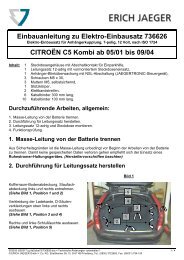
Inhalt: 1 Leitungsstrang 1 Klettband 1 Blechschraube 1 Y-Verbinder<br />
1 Steckdose 1 Sicherung 10A 1 Schraube M5 x 10 15 Kabelbinder 140mm<br />
1 Steckdosendichtung 1 Sicherungshalter 3 Schrauben M5 x 35 3 Kabelbinder 300mm<br />
1 Modul UN-09 1 Leitung rot 4 Muttern M5<br />
1 Gummitülle 2 Steckhülsen 4 Sprengringe<br />
1. Bitte klemmen Sie das Massekabel an der Batterie ab!<br />
2.<br />
Anbauanweisung<br />
Entfernen Sie die folgenden Abdeckungen und Verkleidungen: Wagenheber, Verkleidung der rechten und linken<br />
Seite des Kofferraumes, Rückleuchte rechts/links und Linke Radhausverkleidung<br />
3. Zur Durchführung des Kabelstranges (Anschluss Steckdose) bohren im linken Radhaus ein 40mm Loch.<br />
4. Schließen Sie den Kabelsatz wie folgt an:<br />
a) Das Leitungssatzende 7polig (Kit 132907) und 12polig (Kit 132913) mit vormontierter Steckdose durch die<br />
unter Punkt 3 angebrachte Durchführung vom Kofferraum nach außen und weiter durch das Loch am<br />
Steckdosenhalter verlegen. Befestigen Sie die am Leitungsstrang befindliche Kabeltülle in der<br />
fahrzeugseitigenDurchführung.<br />
b) Es sind zwei verschiedene Gummidichtungen <strong>für</strong> die Steckdose montiert. Einer <strong>für</strong> den seitlichen und einer<br />
<strong>für</strong> den axialen Ausgang.<br />
Seitliche Ausführung: Bei starrer AHK mit geschlossenem Steckdosenhalter und bei abnehmbarer AHK<br />
mit abklappbaren Steckdosenhalter. Hierzu den vorgestanzten Innenteil des Steckdosengehäuses<br />
herraustrennen. Wichtig !!! Bei abklappbaren Steckdosenhalter, Steckdosenabdichtung mit seitlichem<br />
Ausgang benutzen. Die Dichtung mit dem axialen Ausgang kann abgetrennt werden (wird nicht benötigt).<br />
Axiale Ausführung: Bei starrer AHK mit geöffnetem Steckdosenhalter und bei abnehmbarer AHK ohne<br />
abklappbaren Steckdosenhalter.<br />
Die Dichtung mit dem seitlichen Ausgang kann abgetrennt werden (wird nicht benötigt).<br />
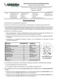
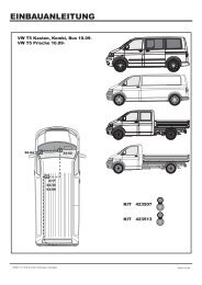
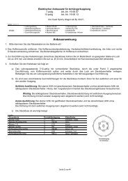
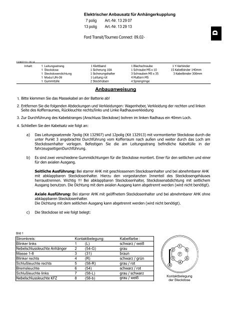
c) Die Steckdose ist wie folgt belegt:<br />
Bild 1<br />
Stromkreis:<br />
Blinker links<br />
Nebelschlussleuchte Anhänger<br />
Masse 1-8<br />
Blinker rechts<br />
Schlußleuchte rechts<br />
Bremsleuchte<br />
Schlußleuchte links<br />
Nebelschlussleuchte KFZ<br />
Kontaktbelegung:<br />
1 (L)<br />
2 (54-G)<br />
3 (31)<br />
4 (R)<br />
5 (58-R)<br />
6 (54)<br />
7 (58-L)<br />
8 (58-b)<br />
Kabelfarbe :<br />
schwarz / weiß<br />
grau<br />
braun<br />
schwarz / grün<br />
grau / rot<br />
schwarz / rot<br />
grau / schwarz<br />
grau / weiß<br />
8<br />
2<br />
3<br />
1<br />
7<br />
4<br />
6<br />
5<br />
Kontaktbelegung<br />
der Steckdose
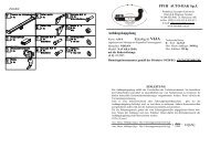
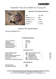
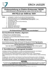
Bild 2<br />
Stromkreis:<br />
Kontaktbelegung:<br />
Blinker links<br />
Nebelschlußleuchte Anhänger<br />
Nebelschlußleuchte KFZ<br />
Masse 1-8<br />
Blinker rechts<br />
Schlußleuchte rechts<br />
Bremsleuchte<br />
Schlußleuchte links<br />
Rückfahrleuchte<br />
Dauerplus Anhänger<br />
Ladeleitung<br />
Masse <strong>für</strong> Ladeleitung<br />
Frei<br />
Masse <strong>für</strong> Dauerplus<br />
1<br />
2<br />
2a<br />
3<br />
4<br />
5<br />
6<br />
7<br />
8<br />
9<br />
10<br />
11<br />
12<br />
13<br />
(L)<br />
(54-G)<br />
(31)<br />
(R)<br />
(58R)<br />
(54)<br />
(58L)<br />
(RFS)<br />
(30)<br />
(15)<br />
(31)<br />
(31)<br />
Kabelfarbe :<br />
schwarz / weiß<br />
grau<br />
grau / weiß<br />
braun<br />
schwarz / grün<br />
grau / rot<br />
schwarz / rot<br />
grau / schwarz<br />
blau / rot<br />
rot / blau 2,5mm²<br />
gelb 2,5mm2<br />
weiß / braun 2,5mm²<br />
frei<br />
weiß / braun 2,5mm²<br />
10<br />
11<br />
9<br />
2<br />
12<br />
8<br />
1<br />
3<br />
4<br />
13<br />
7<br />
6<br />
5<br />
2a<br />
Kontaktbelegung<br />
der Steckdose<br />
5. Gummidichtung und Steckdose mit den beiliegenden Schrauben und Muttern am Steckdosenhalter befestigen.<br />
a) Auf ordnungsgemäßen Sitz der Dichtung achten!<br />
b) Leitungssatz so verlegen, dass keine Scheuer- oder Knickstellen entstehen können!<br />
6. Das Leitungssatzende das mit L gekennzeichnet ist, entlang zu der linken Rückleuchte verlegen und das<br />
fahrzeugseitige Steckgehäuse 6-fach der linken Rückleuchte entfernen.<br />
7.<br />
a) Das fahrzeugseitige Steckgehäuse 6-fach der linken Rückleuchte mit den passenden Gegenstück des<br />
Leitungssatzes zusammenstecken und verrasten.<br />
b) Das verbleibende Steckgehäuse 6-fach des Leitungssatzes auf den Stecker der linken Rückleuchte<br />
stecken und verrasten.<br />
c) Das beiliegende Modul auf das Steckgehäuse 14-fach des Leitungssatzes stecken und an geeigneter<br />
Stelle mit der Schraube M5x10 und Kabelbindern befestigen. Es ist besonders darauf zu achten, das<br />
keine Feuchtigkeit in das Modul eindringen kann (Kurzschlussgefahr).<br />
d) Die Ringöse der Leitungen braun (und weiß / braun 2,5 mm² bei 13pol) an einen geeigneten<br />
Massepunkt anschließen. (ggf. 3 mm Loch bohren und mit beiliegender Blechschraube befestigen.<br />
Bohrung nicht mit Korrosionsschutz behandeln.)<br />
Das Leitungssatzende das mit R gekennzeichnet ist, entlang zu der rechten Rückleuchte verlegen und das<br />
fahrzeugseitige Steckgehäuse 6-fach der rechten Rückleuchte entfernen.<br />
a) Das fahrzeugseitige Steckgehäuse 6-fach der rechten Rückleuchte mit den passenden Gegenstück des<br />
Leitungssatzes zusammenstecken und verrasten.<br />
b) Das verbleibende Steckgehäuse 6-fach des Leitungssatzes auf den Stecker der rechten Rückleuchte<br />
stecken und verrasten.<br />
8. Spannungsversorgung Modul<br />
Auf der rechten Fahrzeugseite die Isolierung des fahrzeugseitigen Leitungsstranges öffnen und die orange<br />
Leitung <strong>für</strong> die Plusversorgung des Steuergerätes ausmessen und durchtrennen. Beide Enden ca. 5mm<br />
abisolieren und an die Leitungsenden die Steckhülsen ancrimpen. Den Y-Verbinder anschließen und mit dem<br />
Sicherungshalter verbinden.
9. Stromversorgung Anhänger:<br />
Das Steckgehäuse 3-fach (Leitungen rot/blau, gelb und weiß/braun) ist <strong>für</strong> eine Erweiterung der<br />
Steckdosenfunktionen vorgesehen. Dieses Teil des Leitungssatzes hinter die Verkleidung legen. Für die<br />
Erweiterung der Steckdosenfunktionen kann ein Erweiterungssatz bestellt werden.<br />
Funktion Dauerplus und Masse Bestellnr. 99 07 99<br />
Funktion Dauerplus, Ladeleitung und Masse Bestellnr. 99 06 99<br />
Funktionshinweis Anhänger-Blinküberwachung:<br />
Ein Defekt der Blinker des Anhängers wird im Anhängerbetrieb von der fahrzeugseitigen Kontrollleuchte über eine<br />
Erhöhung der Blinkfrequenz angezeigt!!<br />
Alle Leitungsstränge mit beiliegenden Kabelbindern befestigen, alle Verkleidungen und demontierten Teile wieder<br />
einbauen.<br />
Der <strong>Elektrosatz</strong> ist nicht diagnosefähig und das Bordnetzsteuergerät wird nicht codiert.<br />
Die Batterie wieder anschließen und sämtliche Fahrzeugfunktionen mit angeschlossenem Anhänger oder einem<br />
geeigneten Prüfgerät überprüfen.<br />
Die <strong>Einbauanleitung</strong> ist dem Kunden auszuhändigen!!!
Electrical Set for Trailer Connection<br />
7-pin Part no. 13 29 07<br />
13-pin Part no. 13 29 13<br />
<strong>Ford</strong> Transit/<strong>Tourneo</strong> Connect manufactured 09.02-<br />
GB<br />
132907/13 / 05.14<br />
Packing list: 1 Cable 1 Self-adhesive tape 1 Sheet-metal screw 1 Y junction<br />
1 Socket 1 Fuse 10A 1 Screws M5 x 10 15 Cable ties 140mm<br />
1 Socket retaining plate 1 Fuse base 3 Screws M5 x 35 3 Cable ties 300mm<br />
1 Module UN-09 1 Cable red 4 Nuts M5<br />
1 Rubber grommet 2 Socket contact 4 Spring washer<br />
Installation instruction<br />
1. Disconnect the earth lead from the battery.<br />
2. Remove the following parts, coverings and sheathings: jack, left- and right-hand side boot coverings, right and left<br />
tail lights, wheel housing covering.<br />
3. To install the cable loom (connecting socket), drill a 40 mm hole in the left wheel housing.<br />
4. Connect the cable loom as follows:<br />
a) Pass the 7-lead (kit 132907) or 12-lead (Kit 132913) end of the cable loom with the preassembled socket<br />
through the hole drilled in step 2 from the inside of the boot to the outside and on to and through the hole of<br />
the socket carrier. Install the grommet provided on the cable in the passage hole for the cable.<br />
b) There are two different washers under the socket. One is used by side entrance of leads, the other - in axis<br />
entrance.<br />
Side entrance: used in permanent assembly of tow hook with closed socket holder and detached tow<br />
hook with folded socket holder. In such event, remove overpass in casing of connection socket.<br />
Note !!! Use washer under socket assigned to side entrance for folded socket holder. Remove the other<br />
washer assigned for axis entrance (it will not be used).<br />
Axis entrance: used in permanent assembly of tow hook with opened socket holder and detached tow<br />
hook without folded socket holder.<br />
Remove washer assigned for side entrance (it will not be used).<br />
c) Socket is connected according to the following scheme<br />
Picture1<br />
Function:<br />
Indicator left<br />
Fog light<br />
Earth<br />
Indicator right<br />
Tail light right<br />
Stop light<br />
Tail light left<br />
Fog light<br />
Contact description:<br />
1 (L)<br />
2 (54-G)<br />
3 (31)<br />
4 (R)<br />
5 (58-R)<br />
6 (54)<br />
7 (58-L)<br />
8 (58-b)<br />
Cable colour:<br />
black/white<br />
grey<br />
brown<br />
black/green<br />
grey/red<br />
black/red<br />
grey/black<br />
grey/white<br />
8<br />
2<br />
3<br />
1<br />
7<br />
4<br />
6<br />
5<br />
Contact description in<br />
7-pin socket
Picture2<br />
Function<br />
Indicator left<br />
Trailer fog light<br />
Earth<br />
Indicator right<br />
Tail light right<br />
Stop light<br />
Tail light left<br />
Reversing light<br />
Trailer current supply<br />
Charge line plus<br />
Charge line earth<br />
Not assigned<br />
Earth (trailer)<br />
Contact description<br />
1<br />
2<br />
3<br />
4<br />
5<br />
6<br />
7<br />
8<br />
9<br />
10<br />
11<br />
12<br />
13<br />
Cable colour<br />
black/white<br />
grey<br />
brown<br />
black/green<br />
grey/red<br />
black/red<br />
grey/black<br />
blue/red<br />
red/blue 2,5mm 2<br />
yellow 2,5mm 2<br />
white/brown 2,5mm 2<br />
white/brown 2,5mm 2<br />
10<br />
11<br />
9<br />
2<br />
12<br />
8<br />
1<br />
3<br />
4<br />
13<br />
7<br />
Contact description in<br />
13-pin socket<br />
6<br />
5<br />
2a<br />
5. Push the socket with rubber retaining plate and screw the socket tightly onto the retaining plate using the supplied<br />
nuts and screws:<br />
a) Pay special attention to the right position of rubber retaining plate,<br />
b) Put the cable set gently to avoid any folds and to secure it from possible wiping.<br />
6. Lead the end of the cable loom marked L to the left-hand taillight and remove the vehicle-side 6-pin socket<br />
housing of the left-hand taillight.<br />
a) Connect the vehicle-side 6-pin connector of the left-hand taillight to the matching counter piece of the<br />
cable loom and lock it.<br />
b) Push the remaining connector 6-pin socket of the cable loom onto the plug of the left-hand taillight and<br />
lock it. Put the taillight back in place.<br />
c) Plug the supplied module onto the 14-pin socket of the cable loom and attach it using the M5 x 10 screw<br />
and zip ties. Take extra care that moisture cannot enter the module (danger of short circuiting).<br />
d) Attach the ring eyelets of the brown (and white/brown leads to a suitable ground point. (If necessary,<br />
drill a 3 mm hole and attach the eyelets with the supplied sheet metal screw. (Do not treat the hole with anticorrosive<br />
primer.)<br />
7. Lead the end of the cable loom marked R to the right-hand taillight and remove the vehicle-side 6-pin socket<br />
housing of the right-hand taillight.<br />
a) Connect the vehicle-side 6-pin socket housing of the right taillight with its counterpart on the cable loom<br />
and lock it.<br />
b) Connect the remaining 6-pin socket housing of the cable loom to the plug of the right taillight and lock it.<br />
8. Module power supply<br />
On the right side of the vehicle, open the insulation of the vehicle-side cable loom, check the orange-coloured lead<br />
of the power supply of the control unit and cut it. Strip both ends on a length of approx. 5 mm and crimp on end<br />
sleeves. Connect the Y junction and this with the fuse holder.
9. Trailer power supply:<br />
3-pin connector housing (red/blue, yellow, and white/brown cables) is provided for expanded socket functions. Put<br />
this part of cable set behind the trim. To expand socket functions it is necessary to order the following parts:<br />
Function “current supply and earth” part no. 99 07 99<br />
Function “current supply, charge line and earth” part no. 99 06 99<br />
Remarks regarding trailer indicator operation:<br />
Trailer indicator defect is signalled by a control light of the vehicle by increased flashing frequency!!<br />
The electric set is not trouble-shootable and the deck network control is not coded.<br />
Fix all the leads with supplied band clips, assemble previously disassembled parts.<br />
Connect accumulator and check all vehicle functions with connected trailer or other suitable testing device.<br />
Assembly instruction for the customer.