DCG - Horn Magyarország Kft.
DCG - Horn Magyarország Kft.
DCG - Horn Magyarország Kft.
- Keine Tags gefunden...

Sie wollen auch ein ePaper? Erhöhen Sie die Reichweite Ihrer Titel.
YUMPU macht aus Druck-PDFs automatisch weboptimierte ePaper, die Google liebt.
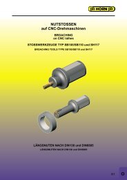
TECHNOLOGIEVORSPRUNG IST HORNHORN - LEADERS IN GROOVING TECHNOLOGYNEUNEWSystem DCZirkularfräsen:· Gewinde Teilprofil· Gewinde Vollprofil· Nutfräsen· Fasfräsen■ EINSTECHEN■ GROOVING■ ABSTECHEN■ PARTING OFF■ NUTFRÄSEN■ GROOVE MILLING■ NUTSTOSSEN■ BROACHING■ KOPIERFRÄSEN■ PROFILE MILLING■ BOHREN■ DRILLING■ REIBEN■ REAMINGCopyright © Paul <strong>Horn</strong> GmbHSystem <strong>DCG</strong>roove Milling by circularinterpolation:· Thread Milling Partial Profile· Thread Milling Full Profile· Groove Milling· Chamfer MillingHartmetall-WerkzeugfabrikPaul <strong>Horn</strong> GmbHUnter dem Holz 33-3572072 TübingenTel.: +49 (0)7071 / 7004-0Fax: +49 (0)7071 / 7 28 93info@phorn.dewww.phorn.de
Sehr geehrte Kunden,die Vollhartmetallfräser des Systems DC wurden zum Herstellen von Gewinden, Nuten mit Radienoder rechteckigen Querschnitten sowie zum Fasen entwickelt. Ihr besonderes Leistungsvermögenbeweisen die in mehreren Hartmetallsorten lieferbaren Werkzeuge beim Bearbeiten von schwerzerspanbaren Werkstoffen, beispielsweise für die Medizintechnik. Vier Fräserarten erlauben mitihren über 140 Varianten eine anwendungsgerechte Werkzeugauswahl.Alle im Prospekt aufgeführten Produkte führen wir als Lagerware, die wir Ihnen jederzeit schnellliefern können.Nutzen Sie das Fachwissen unserer Innen- und Außendienstmitarbeiter. Denn wir kennen den Marktund wissen auf Ihre Fragen eine fachliche Antwort.Die Paul <strong>Horn</strong> GmbH garantiert Ihnen in jahrzehntelanger Erfahrung Marktübersicht, ständigtechnisch ausgereifte Produkte, Service und fachliche Beratung.Auf gute ZusammenarbeitLothar <strong>Horn</strong>Dear Customer,The solid cutters of the DC system have been developed for machining threads, grooves, both full radii, square cornerand tools specific for chamfering. These cutters, which are available in different carbide grades, demonstrate their abilityin machining of hard materials, used in the medical industry. Four cutter types with more than 140 versions allow anapplication specific tool choice.All tools mentioned this flyer is available from stock.As a HORN user, you gain access to this wealth of experience in grooving. Our team of engineers will be pleased to giveyou the help and assistance necessary to ensure you get the very best performance from our products. If you require anyfurther assistance of information, please do not hesitate to contact us.We are looking forward to our continued cooperation.Yours sincerelyLothar <strong>Horn</strong>2
DC GEWINDEFRÄSER VollprofilDC THREAD ENDMILL Full profileMetrisches ISO-Gewinde DIN13-20 VollprofilMetric ISO-thread DIN13-20 Full profile<strong>DCG</strong>Gewinde Thread M3 - M12BestellnummerPart numberGewindeThreadD minZ P d 1d 2d 3l 1l 3l4MG12ST35<strong>DCG</strong>.3.M3.035.2.2.040,351,40Δ ▲<strong>DCG</strong>.3.M3.050.2.2.04M3 2,4 30,502,0 41,2539 8 22Δ ▲<strong>DCG</strong>.3.M35.050.2.2.04<strong>DCG</strong>.3.M35.060.2.2.04M3,5 2,7 3 0,60 2,3 4 1,80 39 9 22Δ ▲<strong>DCG</strong>.3.M4.050.3.2.060,502,50Δ ▲<strong>DCG</strong>.3.M4.070.3.2.06M4 3,3 30,702,8 61,9050 10 36Δ ▲<strong>DCG</strong>.3.M5.050.3.2.060,502,85Δ ▲<strong>DCG</strong>.3.M5.080.3.2.06M5 4,2 30,803,6 62,5050 10 36Δ ▲<strong>DCG</strong>.4.M6.075.5.2.060,753,10Δ ▲<strong>DCG</strong>.4.M6.100.5.2.06M6 5,0 41,004,2 62,8063 16 40Δ ▲<strong>DCG</strong>.4.M8.075.5.2.080,754,30<strong>DCG</strong>.4.M8.100.5.2.08 M8 6,5 4 1,00 5,5 8 4,00 63 16 40 Δ ▲<strong>DCG</strong>.4.M8.125.5.2.08 1,25 3,70 Δ ▲<strong>DCG</strong>.4.M10.075.6.2.080,755,60 63 20 36 Δ ▲<strong>DCG</strong>.4.M10.100.6.2.08 1,00 5,40 63 20 36 Δ ▲M10 8,0 46,8 8<strong>DCG</strong>.4.M10.100.7.2.08 1,00 5,40 77 25 40 Δ ▲<strong>DCG</strong>.4.M10.150.6.2.08 1,50 4,70 63 20 36 Δ ▲<strong>DCG</strong>.4.M12.100.6.2.101,006,30 63 20 36 Δ ▲<strong>DCG</strong>.4.M12.125.8.2.10 1,25 6,10 77 30 40 Δ ▲M12 10,0 48,0 10<strong>DCG</strong>.4.M12.175.6.2.10 1,75 5,50 63 20 36 Δ ▲<strong>DCG</strong>.4.M12.175.8.2.10 1,75 5,50 77 30 40 Δ ▲▲ ab Lager / on stock Δ 4 Wochen / 4 weeks P ο ●● Haupteinsatzbereich / main recommendation M ο ●ο bedingt einsetzbar / alternative recommendation K ● ●███ unbeschichtete HM-Sorten / uncoated grades S ●███ beschichtete HM-Sorten / coated grades N ●███ bestückt/Cermet / brazed/Cermet H οAbmessungen in mmDimensions in mmHM-SortenCarbide grades5
DC NUTFRÄSER VollradiusDC GROOVE ENDMILL Full radiusNutfräsenGroove millingDCRSchneidkreis-ØVollradiusNuttiefeCutting edge ØFull radiusDepth of groove4,0 - 10,0 mm0,5 - 1,5 mm0,5 - 2,0 mmBestellnummerPart numberZ w t maxr d 1d 2d 3l 1l 3l4MG12ST35DCR.3.40.10.05.1.06 3 1,0 0,5 0,50 4 6 2,75 50 4 36 Δ ▲DCR.3.60.10.05.1.061,00,5050 4 36 Δ ▲DCR.3.60.10.05.2.06 3 1,0 1,0 0,50 6 6 3,70 63 6 40 Δ ▲DCR.3.60.15.75.2.06 1,5 0,75 63 6 40 Δ ▲DCR.4.80.15.75.3.081,50,758Δ ▲DCR.4.80.20.10.3.08 2,0 1,00 8 Δ ▲41,58 8 4,60 6340DCR.4.80.15.75.5.08 1,5 0,75 16 Δ ▲DCR.4.80.20.10.5.08 2,0 1,00 16 Δ ▲DCR.4.100.10.05.6.101,00,50Δ ▲DCR.4.100.15.75.6.10 1,5 0,75 Δ ▲DCR.4.100.20.10.6.10 4 2,0 2,0 1,00 10 10 5,50 77 20 55Δ ▲DCR.4.100.25.12.6.10 2,5 1,25 Δ ▲DCR.4.100.30.15.6.10 3,0 1,50 Δ ▲▲ ab Lager / on stock Δ 4 Wochen / 4 weeks P ο ●● Haupteinsatzbereich / main recommendation M ο ●ο bedingt einsetzbar / alternative recommendation K ● ●███ unbeschichtete HM-Sorten / uncoated grades S ●███ beschichtete HM-Sorten / coated grades N ●███ bestückt/Cermet / brazed/Cermet H οAbmessungen in mmDimensions in mmHM-SortenCarbide grades8
DC NUTFRÄSERDC GROOVE ENDMILLNutfräsenGroove millingDCNSchneidkreis-ØNutbreiteNuttiefeCutting edge ØWidth of grooveDepth of groove4,0 - 10,0 mm0,5 - 3,0 mm0,5 - 2,0 mmBestellnummerPart numberZ w t maxr d 1d 2d 3l 1l 3l4MG12ST35DCN.3.40.05.00.1.060,5Δ ▲DCN.3.40.10.00.1.0631,00,5 - 4 6 2,8 50 4 36Δ ▲DCN.3.60.10.00.1.061,0-50 4 36 Δ ▲DCN.3.60.10.00.2.06 3 1,0 1,0 - 6 6 3,7 63 6 40 Δ ▲DCN.3.60.15.15.2.06 1,5 0,15 63 6 40 Δ ▲DCN.4.80.15.15.3.081,58Δ ▲DCN.4.80.20.15.3.08 2,0 8 Δ ▲41,5 0,15 8 8 4,6 6340DCN.4.80.15.15.5.08 1,5 16 Δ ▲DCN.4.80.20.15.5.08 2,0 16 Δ ▲DCN.4.100.10.00.6.101,0-Δ ▲DCN.4.100.15.00.6.10 1,5 - Δ ▲DCN.4.100.20.15.6.10 4 2,0 2,0 0,15 10 10 5,5 77 20 50Δ ▲DCN.4.100.25.15.6.10 2,5 0,15 Δ ▲DCN.4.100.30.15.6.10 3,0 0,15 Δ ▲▲ ab Lager / on stock Δ 4 Wochen / 4 weeks P ο ●● Haupteinsatzbereich / main recommendation M ο ●ο bedingt einsetzbar / alternative recommendation K ● ●███ unbeschichtete HM-Sorten / uncoated grades S ●███ beschichtete HM-Sorten / coated grades N ●███ bestückt/Cermet / brazed/Cermet H οAbmessungen in mmDimensions in mmHM-SortenCarbide grades9
DC NUTFRÄSERDC GROOVE ENDMILLNutfräsenGroove millingDCXSchneidkreis-ØNutbreiteNuttiefeCutting edge ØWidth of grooveDepth of groove20,0 - 40,0 mm1,5 - 2,0 mm6,5 - 13,5 mmBestellnummerPart numberZ w t maxd 1d 2d 3l 1l 3MG12ST35DCX.6.20.150.2.06.10 6 1,5 6,5 20 10 6 63 6 Δ ▲DCX.6.30.200.4.09.12 6 2,0 10,0 30 12 9 80 9 Δ ▲DCX.8.40.200.4.12.12 8 2,0 13,5 40 12 12 80 - Δ ▲▲ ab Lager / on stock Δ 4 Wochen / 4 weeks P ο ●● Haupteinsatzbereich / main recommendation M ο ●ο bedingt einsetzbar / alternative recommendation K ● ●███ unbeschichtete HM-Sorten / uncoated grades S ●███ beschichtete HM-Sorten / coated grades N ●███ bestückt/Cermet / brazed/Cermet H οAbmessungen in mmDimensions in mmHM-SortenCarbide grades10
DC FASFRÄSERDC CHAMFER ENDMILLFasfräsenChamfer millingDCFSchneidkreis-ØFasbreiteFastiefeCutting edge ØWidth of chamferDepth of groove2,0 - 7,5 mm45°0,3 - 1,5 mmBestellnummerPart numberZ w FaseChamfert maxd 1d 2d 3l 1l 3l4MG12ST35DCF.3.20.4545.1.04 3 0,2 45° 0,30 2,0 4 1,25 39 4 22 Δ ▲DCF.3.30.4545.2.04 3 0,2 45° 0,30 3,0 4 2,10 39 6 22 Δ ▲DCF.3.40.4545.3.06 3 0,2 45° 0,75 4,0 6 2,20 50 8 36 Δ ▲DCF.3.50.4545.3.06 3 0,2 45° 1,00 5,0 6 2,70 50 10 36 Δ ▲DCF.3.60.4545.5.0616Δ ▲DCF.3.60.4545.6.063 0,2 45° 1,50 6,0 6 2,80 632040Δ ▲DCF.3.75.4545.6.08 363 20Δ ▲DCF.3.75.4545.8.08 3 0,2 45° 1,50 7,5 8 4,10 77 30 40Δ ▲DCF.4.75.4545.8.08 4 77 30 Δ ▲▲ ab Lager / on stock Δ 4 Wochen / 4 weeks P ο ●● Haupteinsatzbereich / main recommendation M ο ●ο bedingt einsetzbar / alternative recommendation K ● ●███ unbeschichtete HM-Sorten / uncoated grades S ●███ beschichtete HM-Sorten / coated grades N ●███ bestückt/Cermet / brazed/Cermet H οAbmessungen in mmDimensions in mmHM-SortenCarbide grades11
SCHNITTDATENCUTTING DATARichtwerte für Schnittgeschwindigkeit v cund mittlere Spandicke h mzur Berechnung des Vorschubs mittels Schnittdatenprogamm »HCT«.Standard values for cutting speeds v cand medium thickness h mfor calculating feed rates by calculating cutting programm »HCT«.WerkstoffMaterialHärteHardnessBrinell(HB)Schnittgeschwindigkeit v cCutting speed v cMG12ST35Vorschub/Zahn fzFeed/tooth f zP0,2% C 140 180 - 250KohlenstoffstahlCarbon steel0,4% C 180 160 - 2200,6% C 200 140 - 200Legierter StahlAlloyed steelgeglühtannealedvergütetquenchedvergütetquenched180280350150 - 2000,01 - 0,03hochlegierter Stahlhigh alloyed steel(>5%)geglühtannealedgehärtethardened200-100 - 140MStahlgussCast steelRostfreier StahlStainless steelunlegiertunalloyedlegiertalloyedmartensitischferritischmartensitic, ferriticaustenitischaustenitic180220200180130 - 17090 -150 0,02KGraugussCast ironniedrige Festigkeitlow tensile strengthhohe Festigkeithigh tensile strength180250190 - 230KugelgraphitgussSpheroidal graphitecast ironferritischferriticperlitischperlitic160250160 - 2200,01 - 0,03TempergussMalleable cast ironferritischferriticperlitischperlitic125225160 - 220SWarmfeste LegierungHeat resistant alloy (Fe)Warmfeste LegierungHeat resistant alloy(Ni, Co)geglühtannealedgehärtethardenedgeglühtannealedgehärtethardened20027525035060 - 12030 - 900,01 - 0,02NAl-LegierungAl-alloynicht vergütbarnot heat treatablevergütbarheat treatable30-8080-120bis max.up to max.Al-Guss-LegierungAl-cast-alloynicht vergütbarnot heat treatablevergütbarheat treatable80100200 - 6000,02 - 0,04Kupfer-LegierungCopper-alloynicht vergütbarnot heat treatablevergütbarheat treatable90100200 - 40012
TECHNISCHE HINWEISEVorschubswerte und ZeitberechnungEinfach und problemlos lässt sich dies mit demRechenprogramm HCT bewältigen. Wir empfehlen dieSchnittdaten mit diesem Programm zu ermitteln, weilnur so die hohe Zerspanungsleistung und Standzeit derHORN-Zirkularfräser erreicht werden kann. Grundlagender Berechnung finden Sie auf den nachfolgenden Seitendargestellt.HCT(HORN Circular Technology)- sicher und schnell -Ihre Schnittdaten für das Zirkularfräsen vonInnen- und Außennuten sowie das Fräsenvon Linearnuten.Systemvorraussetzung ab Windows 95.Lieferbar auf CD-ROM.GRUNDLEGENDE HINWEISEAuskraglänge des FräsersWählen Sie die Aufnahmen oder die Fräserschäfte sokurz wie möglich und prüfen Sie den Rund- und Planlaufder Werkzeuge.Große Schnittbreiten kombiniert mit hoher Auskraglängeerfordern oftmals technische Maßnahmen wieSchnittaufteilung, um das gewünschte Fräsergebnis zuerreichen.Durchmesser des FräsersRechnerisch ergeben möglichst dem Bohrungsdurchmesserangenäherte Fräserdurchmesser diekleinste Fräsermittelpunktsbahn, damit extrem hoheVorschübe auf der Fräsermittelpunktsbahn und kurzeBearbeitungszeiten.Oftmals wird aber der Durchmesser von denWerkstückgegebenheiten bestimmt.GewindefräsenMit HORN-Zirkulargewindefräsern werden bei vollerFrästiefe die Gewindegänge einzeln abgefahren. Dabeiergeben sich Gewinde mit hoher Zylindrizität, besondersin hochfesten Werkstoffen.In Sacklochbohrungen empfiehlt es sich vomBohrungsgrund nach außen zu arbeiten. Damit vermeidetman das Auffahren auf Späne und vermindert die Gefahrder Beschädigung des Werkzeugs.Als Faustformel beim Gewindefräsen gilt:Das Werkzeug darf nicht größer sein wie 70% desKerndurchmessers, ansonsten schneidet das Werkzeugin den Gewindegängen nach.13
TECHNISCHE HINWEISEFräsrichtungHORN-Zirkularfräswerkzeuge sind rechtsschneidendund es wird empfohlen, wie bei Hartmetall-Werkzeugenüblich, im Gleichlauf zu fräsen.Eintauchen in das WerkstückEinfahrschleife > 45°Einfaches radiales Eintauchen erregt aufgrund des hohenUmschlingungswinkels oftmals Schwingungen, die sichbeim Nutfräsen bis zum Erreichen des Nutgrundes nichtmehr beruhigen.Empfohlen wird deshalb unter 45° bis 180° in einerEinfahrschleife auf Nuttiefe zu fräsen. Die ermitteltenVorschubswerte beziehen sich zwar auf die volle Frästiefe,werden aber auch beim Einfahren beibehalten.14
TECHNICAL INSTRUCTIONSFeed rates and time calculationIt is simple and easy to calculate your speed and feedsusing HORN'S HCT programme. We recommend thatyou calculate the cutting data with this programme asit will provide you with the best cutting performance andresults. Basic features of the calculations can be foundon the follwing pages.HCT(HORN Circular Technology)- safe and fast -Your cutting data for groove milling by circularinterpolation of internal and external groovesas well as groove milling of linear grooves.System requirements from Windows 95.Available on CD-ROM.BASIC RECOMMENDATIONSOverhang of the milling cutterSelect the shortest possible clamping device and millingshank, and control the runout tolerance of the tools.Large cutting widths in combination with long overhangsrequire specific manufacturing methods such as dividingthe cutting width to achieve the best possible cuttingresult due to reduced cutting forces.Diameter of the milling cutterWhen using a large diameter cutter, whose relationshipis close to the bore diameter, manufacturing cycletimecan be reduced, due to the smaller center of rotation andhigher feed rates. Many times the rotation of the millingcutter center will be defined by the parameters of theworkpiece and the whole application setup.Thread millingWith HORN thread milling inserts the thread profile isgenerated in one full cut to the profile depth of the thread.This produces threads with minimal taper especially inhigh alloyed steels.In blind holes it is recommended to mill from the bottomto the top. Otherwise there is the risk of damaging thetool because of milling into chips at the bottom of theblind hole.A general recommendation for thread milling:The milling cutter diameter should not exceed 70% of theminor diameter of the thread. Otherwise recutting of theprofile occurs which could bring the whole thread out oftolerance.15
TECHNICAL INSTRUCTIONSMilling directionMost HORN milling tools are right handed , and it isrecommended to use them with the climb milling processas this is generally recommend for carbide tools.Milling entry into the workpieceRamp angle > 45°A simple radial entry of the milling cutter creates a verylong contact angle which leads to vibrations which willnot disappear for the rest of the milling operation and arevisual on the bottom of the groove.It is recommended to enter the groove with a rampangle of 45° up to 180° to the maximum depth of cut.The calculated cutting data refers to the milling conditionwhen the insert is in the full cut but can be also used forthe entry loop.16
NUTFRÄSEN (Zirkular)GROOVE MILLING by circular interpolationINNENNUTENFRÄSENMILLING OF AN INTERNAL GROOVECos [180° - φ°] = r2 + [R + a r- r] 2 - R 2 180° - φ° φ°2r [R + a r- r]L = • 2r • φ° mm360°EingriffslängeLength of cutt =A Tn • z • A zminGesamt-Zerpanzeit(für A T)Time for cut (for A T)A Z= L • h mmm 2 s' 2= s' 1SpandickeArea of chips' 1= • 2 (R-r+a r ) mm/mintVorschubgeschwindigkeitder FräsmittelpunktsbahnFeed rate of tool centreA T= [(R + a r) 2 - R 2 ] mm 2Insgesamt zuzerspanende FlächeArea of groove sectionR + a rR - r + a rmm/minVorschubgeschwindigkeitder Schneide (Nutgrund-Ø)Feed rate of tool tipBezeichnungSpecificationVorschubgeschwindigkeitFeed rateDrehzahlRevolutionsZähnezahlNumber of teethVorschub/ZahnFeed/toothmittlere Spandickemedium thickness of chipradiale Schnittieferadial depth of cutBezeichnungSpecifications'nzs zh ma rISOBezeichnungSpecificationv fnzf zh ma eVorschubgeschwindigkeitder FräsmittelpunktsbahnFeed rate of tool centreVorschubgeschwindigkeitder Schneide (Nutgrund-Ø)Feed rate of tool tipBezeichnungSpecificationISOBezeichnungSpecificationRadius Fräser r rRadius of cutterRadius WerkstückRRRadius of workpieces‘ 1v f 3s‘ 2v f217HCT (HORN Circular Technology)- safe and fast -Your cutting data for groove milling by circular interpolation of internal and external grooves as well as groove millingof linear grooves.System requirements from Windows 95. Available on CD-ROM.