Integrated 2 l Manual Reservoir Regelbarer Produkttank ... - Henkel
Integrated 2 l Manual Reservoir Regelbarer Produkttank ... - Henkel
Integrated 2 l Manual Reservoir Regelbarer Produkttank ... - Henkel

Sie wollen auch ein ePaper? Erhöhen Sie die Reichweite Ihrer Titel.
YUMPU macht aus Druck-PDFs automatisch weboptimierte ePaper, die Google liebt.
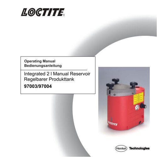
Operating <strong>Manual</strong>Bedienungsanleitung<strong>Integrated</strong> 2 l <strong>Manual</strong> <strong>Reservoir</strong><strong>Regelbarer</strong> <strong>Produkttank</strong>97003/97004
21 2 365psibar4psibar7 8 9P inmax. operating pressure8 baroperating temperature.0 to +50Cvolume:3,5 LiterMade in GermanyLoctite (Ireland) Ltd.
RRRRRRRRR24 681020psibarB10ESCB68ARRRRbarpsiCONT97102On PowerO fRefi lEmptyChangeOn PowerO fRefi lEmptyChange97110971109710597107 97109 97106 97108 9711097003/97004 97005 9700697111 97112971169711597113971149711897119971219712160 8040201 0120psi140bar60 9030 120barSTARTpsiCONT970059700697102 97123 9710397204971129711397114BAESC A97123971031x1x 1x 2x1x1x1x2x2x3
Inhaltsverzeichnis1 Bitte beachten Sie . . . . . . . . . . . . . . . . . . . . . . . . . . . . . . . . . . . . . . . . . . . . . . . 51.1 Hervorhebungen . . . . . . . . . . . . . . . . . . . . . . . . . . . . . . . . . . . . . . . . . . . . . . . . . 51.2 Lieferumfang . . . . . . . . . . . . . . . . . . . . . . . . . . . . . . . . . . . . . . . . . . . . . . . . . . . . 51.3 Zu Ihrer Sicherheit . . . . . . . . . . . . . . . . . . . . . . . . . . . . . . . . . . . . . . . . . . . . . . . . 61.4 Einsatzbereich (Bestimmungsgemäße Verwendung) . . . . . . . . . . . . . . . . . . . . . . . 62 Gerätebeschreibung . . . . . . . . . . . . . . . . . . . . . . . . . . . . . . . . . . . . . . . . . . . . . 72.1 Bedienelemente und Anschlüsse . . . . . . . . . . . . . . . . . . . . . . . . . . . . . . . . . . . . . 72.2 Funktionsbeschreibung . . . . . . . . . . . . . . . . . . . . . . . . . . . . . . . . . . . . . . . . . . . . 73 Technische Daten . . . . . . . . . . . . . . . . . . . . . . . . . . . . . . . . . . . . . . . . . . . . . . . . 84 Installieren . . . . . . . . . . . . . . . . . . . . . . . . . . . . . . . . . . . . . . . . . . . . . . . . . . . . . 84.1 Umgebungs- und Betriebsbedingungen . . . . . . . . . . . . . . . . . . . . . . . . . . . . . . . . 84.2 Platzbedarf . . . . . . . . . . . . . . . . . . . . . . . . . . . . . . . . . . . . . . . . . . . . . . . . . . . . . . 85 Dosieren . . . . . . . . . . . . . . . . . . . . . . . . . . . . . . . . . . . . . . . . . . . . . . . . . . . . . . . 95.1 Erste Inbetriebnahme . . . . . . . . . . . . . . . . . . . . . . . . . . . . . . . . . . . . . . . . . . . . . . 95.1.1 Einsetzen der Produktflasche . . . . . . . . . . . . . . . . . . . . . . . . . . . . . . . . . . . . . . . . 95.1.2 Füllen der Produktleitung . . . . . . . . . . . . . . . . . . . . . . . . . . . . . . . . . . . . . . . . . . . 105.1.3 Einstellen der Dosiermenge . . . . . . . . . . . . . . . . . . . . . . . . . . . . . . . . . . . . . . . . . 105.2 Nachfüllen des regelbaren <strong>Produkttank</strong>s . . . . . . . . . . . . . . . . . . . . . . . . . . . . . . . 115.3 Außerbetriebnahme . . . . . . . . . . . . . . . . . . . . . . . . . . . . . . . . . . . . . . . . . . . . . . . 115.4 Erneute Inbetriebnahme . . . . . . . . . . . . . . . . . . . . . . . . . . . . . . . . . . . . . . . . . . . . 116 Pflege, Reinigung und Wartung . . . . . . . . . . . . . . . . . . . . . . . . . . . . . . . . . . . . . 127 Beseitigen von Störungen . . . . . . . . . . . . . . . . . . . . . . . . . . . . . . . . . . . . . . . . . 137.1 Auswechseln der Berstscheibe . . . . . . . . . . . . . . . . . . . . . . . . . . . . . . . . . . . . . . 138 Technische Unterlagen . . . . . . . . . . . . . . . . . . . . . . . . . . . . . . . . . . . . . . . . . . . 148.1 Zubehör und Ersatzteile . . . . . . . . . . . . . . . . . . . . . . . . . . . . . . . . . . . . . . . . . . . . 144
1Bitte beachten Sie1.1 HervorhebungenGefahr!Verweist auf Sicherheitsregeln und fordert Vorsichtsmaßnahmen, die den Betreiber desGerätes oder andere Personen vor Verletzungen oder Lebensgefahr schützen.Achtung!Hebt hervor, was getan oder unterlassen werden muß, um das Gerät oder andere Sachwertenicht zu beschädigen.☞GibtHinweisEmpfehlungen zum besseren Handhaben des Gerätes bei Bedien- und Einstellvorgängen sowiePflegearbeiten.Die halbfett gedruckten Zahlen im Text beziehen sich auf die entsprechende Positionsnummer in derAbbildung auf Seite 2.• Der Punkt hebt einen Handlungsschritt hervor.Handlungsschritte in Abbildungen sind durchPfeile dargestellt.Werden mehrere Handlungsschritte in einerAbbildung dargestellt, bedeutet einSchwarzer Pfeil = 1. HandlungsschrittGrauer Pfeil = 2. HandlungsschrittWeißer Pfeil = 3. Handlungsschritt1.2 Lieferumfang☞Bedingt1 <strong>Regelbarer</strong> <strong>Produkttank</strong>97003 Druckbereich: 0 … 1 bar (0 … 14,5 psi); Viskosität des Klebstoffes: 1 … 1500 mPas.97004 Druckbereich: 0 … 8 bar (0 … 116 psi); Viskosität des Klebstoffes: 1500 … 10 000 mPas.3 Auffangbehälter;1 Bedienungsanleitung 97003 / 97004.durch die technische Entwicklung können Abbildungen und Beschreibungen in dieserBedienungsanleitung vom tatsächlich ausgelieferten Gerät in Details abweichen.5
1Bitte beachten Sie1.3 Zu Ihrer SicherheitFür den gefahrlosen und erfolgreichen Einsatz des Gerätes diese Anleitung vollständig lesen.Werden die Anweisungen nicht befolgt, übernimmt der Hersteller keine Gewährleistung.Bei unsachgemäßem Umgang mit chemischen Produktenkönnen Gesundheitsschäden auftreten.• Allgemeine Sicherheitsvorschriften für den Umgang mit Chemikalien beachten!• Herstellerhinweise beachten!Sicherheitsdatenblatt des eingesetzten LOCTITE-Produkts anfordern!• Beim Arbeiten mit Druckluft Schutzbrille tragen!• Vor dem Lösen der Deckelverschraubung muß der <strong>Produkttank</strong> entlüftet (drucklos) sein!• Das Gerät darf nur vom autorisierten LOCTITE-Service repariert werden.Niemals das Produkt direkt in den Tank füllen!Die Sicherheitseinrichtungen werden verklebtund dadurch unwirksam!Das Produkt nur im LOCTITE-Originalgebindeeinsetzen!1.4 Einsatzbereich (Bestimmungsgemäße Verwendung)Der regelbare <strong>Produkttank</strong> eignet sich zum Auftragen von LOCTITE-Klebstoffen mit einemHanddosierventil an Handarbeitsplätzen, wie in Werkstätten, Labors und industriellen Einrichtungen.Es ist möglich, anaerobe, UV-aushärtende und Cyanacrylat-Klebstoffe zu dosieren.97003 Druckbereich: 0 … 1 bar (0 … 14,5 psi); Viskosität des Klebstoffes: 1 … 1500 mPas.97004 Druckbereich: 0 … 8 bar (0 … 116 psi); Viskosität des Klebstoffes: 1500 … 10 000 mPas.6Außer den LOCTITE-Originalgebinden für 250 ml (anaerobe Klebstoffe) und 500 g (CA-Klebstoffe)können auch LOCTITE-Klebstoffe aus Gebinden mit einer maximalen Höhe von 250 mm und einemmaximalen Außendurchmesser von 125 mm verarbeitet werden.
2Gerätebeschreibung2.1 Bedienelemente und Anschlüsse☞• Siehe Abbildung Seite 2.1 Deckel2 Deckelverschraubung3 Produktanschluß 1 /4" für Produktschlauch 1 /4" (Lieferumfang des Handdosierventils)4 Be- und EntlüftungsventilSchalterstellung – Der <strong>Produkttank</strong> ist entlüftet.Schalterstellung – Der <strong>Produkttank</strong> kann belüftet werden.5 DruckreglerRegler zum Einstellen des Dosierdrucks.Durch Ziehen und anschließendes Drehen des Reglerknopfes wird der Dosierdruck entsprechenddem Druckbereich des <strong>Produkttank</strong>s eingestellt. Nach dem Loslassen rastet der Reglerknopf ein undverhindert somit ein unbeabsichtigtes Verändern der Einstellung.Den gewünschten Druck immer im Uhrzeigersinn von unten nach oben einstellen. Soll zum Beispielder Druck von 3 bar auf 2 bar verringert werden, dann zuerst durch Drehen gegen den Uhrzeigersinnden Druck von 3 bar auf 1 bar verringern und danach durch Drehen im Uhrzeigersinn auf 2 barerhöhen. Durch dieses Verfahren ist eine stabile Einstellung des Druckes gewährleistet.6 ManometerAnaloge Anzeige des Dosierdrucks entsprechend dem Druckbereich des <strong>Produkttank</strong>s.7 Druckluftanschluß P in8 Deckelablage mit Trichter9 AuffangbehälterHierfür kann jeglicher geeignete Behälter aus PP oder PE verwendet werden.2.2 FunktionsbeschreibungDie Produktflasche wird in den <strong>Produkttank</strong> eingesetzt.Mit dem integrierten Druckregler 5 wird der Dosierdruck des <strong>Produkttank</strong>s eingestellt. Solange dasHanddosierventil geöffnet ist, wird durch pneumatischen Druck auf die Flüssigkeitsoberfläche in derProduktflasche der Klebstoff durch die Produktleitung gefördert.Die Dosiermenge hängt ab– vom eingestellten Dosierdruck,– von der Öffnungszeit des Dosierventils und– von der Größe der Dosiernadel.7
R3Technische DatenDruckluftversorgungmax. 8 bar (116 psi)Qualitätgefiltert 10 µm, ölfrei, nicht kondensierendWird die geforderte Qualität nicht erreicht,LOCTITE-Wartungseinheit installieren. Zubehör-Bestellnummer 97120Überdrucksicherung (Berstscheibe)min. 9 bar (130.5 psi); max. 12,5 bar (174 psi)Anzugsmoment der Berstscheibemax. 20 NmSchlauchgröße Druckluftanschluß P in Außen-Ø 6 mm+0,05–0,10 ;Außen-Ø 1 /4" nicht geeignet!AbmessungenB x H x T: 235 x 335 x 360 mmBetriebstemperatur+10 °C bis +40 °C (+50 °F bis +104 °F)Lagertemperatur–10 °C bis +60 °C (+14 °F bis +140 °F)Gewicht6,50 kgDauerschalldruckpegel< 50 dB(A)4Installieren4.1 Umgebungs- und Betriebsbedingungen– Keine kondensierende Luftfeuchtigkeit– Kein Spritzwasser– Ölfreie Druckluft (siehe Kapitel 3)4.2 Platzbedarf235 mm min 150 mm 270 mm450 mm8
psibar5Dosieren5.1 Erste InbetriebnahmeVor dem Lösen der Deckelverschraubung 2muß der regelbare <strong>Produkttank</strong> entlüftet(drucklos) sein!• Entlüftungsventil 4 auf Stellungumschalten.(entlüften)5.1.1 Einsetzen der Produktflasche• Deckelverschraubung 2 lösen und Deckel 1 abnehmen.• Prüfen, daß das Dosierventil gemäß dessen Bedienungsanleitung korrekt angeschlossen ist.Niemals das Produkt direkt in den Tank füllen!Die Sicherheitseinrichtungen werden verklebt und dadurch unwirksam!• Eine volle Produktflasche in den Tank einsetzen.• Den Produktschlauch in die Flasche einführenund den Deckel 1 aufsetzen.• Deckelverschraubung 2 gleichmäßig festziehen.• Druckluftzufuhr am Druckluftanschluß 7 (P in)überprüfen.• Das Entlüftungsventil 4 auf Stellung(belüften) umschalten.P inpsibarLoctite (Ireland) Ltd.Made in Germanymax. operating pressure8 baroperating temperature.0 to +50Cvolume:3,5 LiterP in9
5Dosieren5.1.2 Füllen der Produktleitung☞Um• Prüfen, daß der <strong>Produkttank</strong> und das Dosierventil gemäß deren Bedienungsanleitungen korrektangeschlossen sind.Luftblasen beim Dosieren zu vermeiden, muß die Produktleitung gefüllt und dadurch entlüftetwerden.• Das Dosierventil gemäß dessen Bedienungsanleitung positionieren, um ein blasenfreies Füllen derProduktleitung zu gewährleisten.Auffangbehälter unter das Dosierventil stellen,da Produkt austreten wird.• Mit dem Druckregler 5 den Dosierdruck 0,5 bar(ca. 7 psi) einstellen.• Den Handhebel am Dosierventil drücken, bisdas Produkt blasenfrei aus der Dosiernadelfließt.24 660 801004012020psi1400 bar0108• Bei zähflüssigeren Produkten den Drucklangsam schrittweise erhöhen, bis Produktaustritt.psibarDas Dosierventil so halten, dassunkontrolliertes Herausspritzen von Produktvermieden wird.P inLoctite (Ireland) LtdMade in Germanymax. operating pre sure8 baroperating temperature.0 to +50Cvolume:3,5 Liter5.1.3 Einstellen der Dosiermenge• Den Handhebel am Dosierventil drücken, bis die Dosiermenge erreicht ist.Wird die Dosiermenge zu langsam bzw. zu schnell erreicht:• Am Druckregler 5 den Dosierdruck erhöhen bzw. vermindern.• Den Handhebel am Dosierventil drücken, um die Dosiermenge zu prüfen.• Die beiden letzten Handlungsschritte wiederholen, bis die gewünschte Dosiermenge erreicht wird.Wird die gewünschte Dosiermenge nicht erreicht:• Mit größerer (bzw. kleinerer) Dosiernadel die Handlungsschritte gemäß Abschnitt 5.1.3 wiederholen.10
5Dosieren5.2 Nachfüllen des regelbaren <strong>Produkttank</strong>s☞Wenn Luftblasen beim Dosieren auftreten, muß geprüft werden, ob der <strong>Produkttank</strong> leer ist.• Beim Dosieren von Cyanacrylat-Klebstoffen den <strong>Produkttank</strong> sofort nachfüllen, weil Luft inder Produktleitung zu Aushärtungen von Produkt führt!• Den <strong>Produkttank</strong> von Hand entlüften und prüfen.• Die leere Produktflasche im <strong>Produkttank</strong> gegen eine volle auswechseln.• Den <strong>Produkttank</strong> wieder von Hand belüften.• Das Dosieren mit dem eingestellten Dosierdruck fortsetzen.5.3 Außerbetriebnahme• Regelbaren <strong>Produkttank</strong> von Hand entlüften.• Die Druckluftversorgung unterbrechen.Außerbetriebnahme für längere StillstandszeitenBei Arbeitspausen von länger als 14 Tagen das System außer Betrieb nehmen, umAushärtungen von Produkt zu vermeiden.• Regelbaren <strong>Produkttank</strong> von Hand entlüften.• Die Druckluftversorgung unterbrechen.• <strong>Produkttank</strong> und Dosierventil gemäß Bedienungsanleitung außer Betrieb nehmen.5.4 Erneute Inbetriebnahme• Die Druckluftversorgung wiederherstellen.• Regelbaren <strong>Produkttank</strong> von Hand belüften.• Das Dosieren mit dem eingestellten Dosierdruck fortsetzen.Inbetriebnahme nach längeren Stillstandszeiten• Installation gemäß Kapitel 4 überprüfen.• Inbetriebnahme gemäß Abschnitt 5.1.11
6Pflege, Reinigung und WartungDas Gerät bedarf keiner besonderen Pflege und Wartung.☞Reinigung• Bei Bedarf den Ablagetrichter 8 und Auffangbehälter 9 reinigen.• Vor Stillstandszeiten von mehr als 14 Tagen oder beim Wechsel der Produktart den Produktschlauchmit Dosierventil reinigen.Empfohlene Reinigungsmittel gemäß der Bedienungsanleitung Dosierventil verwenden.Vor dem Lösen der Deckelverschraubung 2 muß der <strong>Produkttank</strong> entlüftet (drucklos) sein!(siehe Abschnitt 5.1)• Deckelverschraubung 2 lösen Deckel 1 abnehmen .Produktreste am Schlauch!• Produktschlauch äußerlich von Produktrestenreinigen.• Produktflasche herausnehmen und durch einGefäß mit ca. 0,5 Liter Reinigungsmittelersetzen.• Deckel 1 aufsetzen und Deckelverschraubung 2 gleichmäßig festziehen.• Im Dauerbetrieb dosieren, bis trockene Luft aus dem Dosierventil ausströmt(siehe Bedienungsanleitung des Dosierventils).• Leeres Reinigungsmittelgefäß wieder entnehmen.12
7Beseitigen von StörungenArt der Störung Mögliche Ursachen AbhilfeKein Zeigerausschlag auf demManometer.– Keine Druckluft vorhanden.– <strong>Produkttank</strong> nicht eingeschaltet.– Manometer defekt.– Druckregler defekt• Druckluftzufuhr sicherstellen.• <strong>Produkttank</strong> überprüfen.Gewünschter Druck wird nichterreicht.Kein, zuwenig bzw. zuvielProdukt.Luftblasen im Produkt– Vordruck unzureichend.– Dosierdruck nicht richtig eingestellt.– Druckluftschlauch nicht richtig angeschlossen.– Dosiernadel verstopft oder zu klein/groß.– Dosierventil nicht richtig angeschlossenoder defekt.– <strong>Produkttank</strong> nicht eingeschaltet.– <strong>Produkttank</strong> leer.– <strong>Produkttank</strong> leer.– Produktschlauch nicht richtigangeschlossen.– Dosierventil nicht richtig angeschlossenoder defekt.– <strong>Produkttank</strong> defekt.• Vordruck erhöhen.• Dosierdruck richtig einstellen.• Druckluftschlauch richtig anschließen.• Dosiernadel auswechseln.• Dosierventil überprüfen(siehe Bedienungsanleitung desDosierventils).• <strong>Produkttank</strong> überprüfen• <strong>Produkttank</strong> nachfüllen(siehe Abschnitt 5.1.1).• <strong>Produkttank</strong> nachfüllen(siehe Abschnitt 5.1.1).• Produktschlauch richtig anschließen.• Dosierventil überprüfen(siehe Bedienungsanleitung desDosierventils).• <strong>Produkttank</strong> überprüfen.Druckluft entweicht zwischenTankgehäuse und Deckel.– Deckelverschraubung nicht festgezogen.– O-Ring undicht.• Deckelverschraubung nachziehen.• O-Ring nachfetten oder erneuern.Druckluft entweicht amProduktanschluß 3.– Überwurfmutter am Produktanschluß 3nicht festgezogen.• Überwurfmutter vorsichtig nachziehen.Druckluft entweicht imTankgehäuse.– Berstscheibe zerstört.– Entlüftungsventil 4 offen oder defekt.• Berstscheibe auswechseln(siehe Seite 14).• Entlüftungsventil 4 schließen.13
psibarP in7Beseitigen von Störungen7.1 Auswechseln der Berstscheibe☞Bei Überschreitung der maximal zulässigen Druckluftversorgung wird der <strong>Produkttank</strong> durch dieBerstscheibe entlüftet. Die zerstörte Berstscheibe muß ausgewechselt werden.• Deckelverschraubung 2 lösen und Deckel 1abnehmen.• Befestigungsschrauben entfernen und Gehäuseaufklappen.Loctite (Ireland) Ltd.Made in Germany• Einschraubmutter für Berstscheibe entfernen.• Die zerstörte Berstscheibe gegen eine neueersetzen.Einschraubmutter für Berstscheibe wiedereinsetzen und festziehen.Anzugsdrehmoment: maximal 20 NmMitgeliefertes Typenschild ankleben.20 Nm• Gehäuse zuklappen. Befestigungsschrauben wieder einsetzen und festziehen.8Technische Unterlagen8.1 Zubehör und ErsatzteilePos. Nr. Bezeichnung Loctite-Bestellnummer– 2 l-Tank Ersatzteilset . . . . . . . . . . . . . . . . . . . . . . . . . . . . . . . . . . . . . . . . . . .97253(1 O-Ring, Silikonfett, 3 Dreikantgriffe, 3 Auffangbehälter)– Berstscheibe . . . . . . . . . . . . . . . . . . . . . . . . . . . . . . . . . . . . . . . . . . . . . . . . .97251– Wartungseinheit . . . . . . . . . . . . . . . . . . . . . . . . . . . . . . . . . . . . . . . . . . . . . .9712014
Contents1 Please Observe the Following. . . . . . . . . . . . . . . . . . . . . . . . . . . . . . . . . . . . . . . 171.1 Emphasized Sections. . . . . . . . . . . . . . . . . . . . . . . . . . . . . . . . . . . . . . . . . . . . . . . 171.2 Items Supplied . . . . . . . . . . . . . . . . . . . . . . . . . . . . . . . . . . . . . . . . . . . . . . . . . . . . 171.3 For Your Safety . . . . . . . . . . . . . . . . . . . . . . . . . . . . . . . . . . . . . . . . . . . . . . . . . . . 181.4 Field of Application (Intended Usage) . . . . . . . . . . . . . . . . . . . . . . . . . . . . . . . . . . . 182 Description . . . . . . . . . . . . . . . . . . . . . . . . . . . . . . . . . . . . . . . . . . . . . . . . . . . . . . 192.1 Operating Elements and Connections . . . . . . . . . . . . . . . . . . . . . . . . . . . . . . . . . . 192.2 Theory of Operation . . . . . . . . . . . . . . . . . . . . . . . . . . . . . . . . . . . . . . . . . . . . . . . . 193 Technical Data . . . . . . . . . . . . . . . . . . . . . . . . . . . . . . . . . . . . . . . . . . . . . . . . . . . 204 Installation . . . . . . . . . . . . . . . . . . . . . . . . . . . . . . . . . . . . . . . . . . . . . . . . . . . . . . 204.1 Environmental and Operating Conditions . . . . . . . . . . . . . . . . . . . . . . . . . . . . . . . . 204.2 Space Requirements . . . . . . . . . . . . . . . . . . . . . . . . . . . . . . . . . . . . . . . . . . . . . . . 205 Dispensing . . . . . . . . . . . . . . . . . . . . . . . . . . . . . . . . . . . . . . . . . . . . . . . . . . . . . . 215.1 First Operation . . . . . . . . . . . . . . . . . . . . . . . . . . . . . . . . . . . . . . . . . . . . . . . . . . . . 215.1.1 Inserting the Product Bottle . . . . . . . . . . . . . . . . . . . . . . . . . . . . . . . . . . . . . . . . . . 215.1.2 Priming the Feedline. . . . . . . . . . . . . . . . . . . . . . . . . . . . . . . . . . . . . . . . . . . . . . . . 225.1.3 Adjusting the Dispensed Quantity. . . . . . . . . . . . . . . . . . . . . . . . . . . . . . . . . . . . . . 225.2 Refilling the <strong>Integrated</strong> 2 l-<strong>Manual</strong> <strong>Reservoir</strong> . . . . . . . . . . . . . . . . . . . . . . . . . . . . . . 235.3 Shutdown . . . . . . . . . . . . . . . . . . . . . . . . . . . . . . . . . . . . . . . . . . . . . . . . . . . . . . . 235.4 Returning to Operation. . . . . . . . . . . . . . . . . . . . . . . . . . . . . . . . . . . . . . . . . . . . . . 236 Care, Cleaning and Maintenance . . . . . . . . . . . . . . . . . . . . . . . . . . . . . . . . . . . . 247 Troubleshooting . . . . . . . . . . . . . . . . . . . . . . . . . . . . . . . . . . . . . . . . . . . . . . . . . . 257.1 Replacing the Rupture Disc . . . . . . . . . . . . . . . . . . . . . . . . . . . . . . . . . . . . . . . . . 258 Documentation. . . . . . . . . . . . . . . . . . . . . . . . . . . . . . . . . . . . . . . . . . . . . . . . . . . 268.1 Accessories and Spare Parts . . . . . . . . . . . . . . . . . . . . . . . . . . . . . . . . . . . . . . . . 2616
1Please observe the following1.1 Emphasized SectionsWarning!Refers to safety regulations and requires safety measures that protect the operator or otherpersons from injury or danger to life.Caution!Emphasizes what must be done or avoidedso that the unit or other property is not damaged.☞GivesNoticerecommendations for better handling of the unit during operation or adjustment as well as forservice activities.The numbers printed in bold in the text refer to the corresponding position numbers in the illustrationon page 2.• The point emphasizes an instruction step.Instruction steps in the illustrations are indicatedwith arrows.When several instruction steps are indicated inan illustration, the shading of the arrow has thefollowing meaning:Black arrow = 1st stepGrey arrow = 2nd stepWhite arrow = 3rd step1.2 Items Supplied☞As1 <strong>Integrated</strong> 2 l-<strong>Manual</strong> <strong>Reservoir</strong>97003 Pressure range: 0 … 1 bar (0 … 14,5 psi); Viscosity of adhesive: 1 … 1500 mPas.97004 Pressure range: 0 … 8 bar (0 … 116 psi); Viscosity of adhesive: 1500 … 10 000 mPas.3 Dripcups1 Instruction <strong>Manual</strong> 97003 / 97004.a result of technical development, the illustrations and descriptions in this instruction manual candeviate in detail from the actual unit delivered.17
1Please observe the following1.3 For Your SafetyFor safe and successful operation of the unit, read these instructions completely.If the instructions are not observed, the manufacturer can assume no responsibility.If chemical products are not properly handled,damage to health can result!• Observe general safety regulations for the handling of chemicals!• Observe manufacturer’s instructions!Request a safety data sheet for the LOCTITE-product used!• When working with pressurized air, wear protective glasses!• Before loosening the cover screw fasteners, the reservoir must be depressurized (pressurefree!)• The unit must be repaired only by an authorized LOCTITE Service agency.Never fill the product directly into thereservoir! The safety devices will becomeclogged and therefore ineffective!Insert only products in original LOCTITEpackaging!1.4 Field of Application (Intended Usage)The integrated 2 l-manual reservoir is suitable for the application of LOCTITE-adhesives with a manualapplicator at manual workstations such as in workshops, laboratories, and industrial installations.It is possible to dispense anaerobic and UV curing as well as cyanacrylate adhesives.97003 Pressure range: 0 … 1 bar (0 … 14,5 psi); Viscosity of adhesive: 1 … 1500 mPas.97004 Pressure range: 0 … 8 bar (0 … 116 psi); Viscosity of adhesive: 1500 … 10 000 mPas.LOCTITE-adhesives can be applied from the original 250 ml (for anaerobic adhesives) and 500 g (forcyanacrylate adhesives) packages as well as from packages with a maximum height of 250 mm and amaximum external diameter of 125 mm.18
2Description2.1 Operating Elements and Connections☞• See the illustration on page 2.1 <strong>Reservoir</strong> lid2 <strong>Reservoir</strong> knob3 <strong>Reservoir</strong> tank fitting 1 /4 in. for product feedline 1 /4 in. (included with the manual applicator)4 Pressurizing / Depressurizing ValveValve Position – The reservoir is depressurized.Valve Position – The reservoir can be pressurized.5 Pressure RegulatorRegulator for setting the dispensing pressure.By pulling and then turning the regulator knob, the dispensing pressure is adjusted in the range from0 to 8 bar (0 to 116 psi) according to the pressure range of the product reservoir. After releasing, theregulator knob re-engages a lock that prevents the setting from being unintentionally changed.Always adjust the desired pressure from lower to higher in the clockwise direction. For example, if thepressure should be reduced from 3 bar to 2 bar, first reduce the pressure by turning in the counterclockwise direction from 3 bar to 1 bar and then increase to 2 bar by turning in the clockwisedirection. With this method, a stable setting of the pressure is ensured.6 Pressure gaugeAnalog indication of the dispensing pressure7 Pneumatic connection P in8 <strong>Reservoir</strong> Lid Holder with Drip Funnel9 DripcupAny suitable container of PP or PE can be used here.2.2 Theory of OperationThe product bottle is inserted into the reservoir.The integrated 2 l-manual reservoir sets the dispensing pressure of the reservoir. As long as themanual applicator is open, pneumatic pressure on the surface of the fluid in the product bottletransports the adhesive through the product feedline.The amount of product dispensed is controlled by:– The dispensing pressure set,– The length of time the dispensing valve remains open and– The size of the dispensing needle.19
R3Technical DataPneumatic supplymax. 8 bar (116 psi)Qualityfiltered 10 µm, oil-free, non-condensingIf the required quality is not achieved,install a LOCTITE filter regulator. Accessory Order No. 97120Over-pressure safety (rupture disk)min. 9 bar (130.5 psi); max. 12,5 bar (174 psi)Tightening torque of the rupture discmax. 20 NmPneumatic hose size external-Ø 6 mm+0,05–0,10 ;external-Ø 1 /4 in. not suitable!DimensionsW x H x D: 235 x 335 x 360 mmOperating temperature+10 °C to +40 °C (+50 °F to +104 °F)Storage temperature–10 °C to +60 °C (+14 °F to +140 °F)Weight6.50 kgContinuous noise level< 50 dB(A)4Installation4.1 Environmental and Operating Conditions– Non-condensing humidity– No splash water– Pressurized air, oil-free (see Chapter 3)4.2 Space Requirements235 mm min 150 mm 270 mm450 mm20
psibar5Dispensing5.1 First OperationBefore loosening the reservoir knob 2,the integrated 2 l-manual reservoir must bedepressurized (pressure-free)!• Set the depressurizing valve 4 to position(depressurize).5.1.1 Inserting the Product Bottle• Loosen the reservoir knob 2 and remove the reservoir lid 1.• Check that the dispensing valve is connected correctly according to the instruction manual.Never fill the product directly into the reservoir!The safety devices will become clogged and therefore ineffective!• Insert a full product bottle in the reservoir.• Insert the product feedline hose into the bottleand put on the reservoir lid 1.• Uniformly tighten the reservoir knob 2.• Check the pneumatic supply at the pneumaticconnection 7 (P in).• Set the depressuirizing valve 4 to position(pressurize).P inpsibarLoctite (Ireland) Ltd.Made in Germanymax. operating pressure8 baroperating temperature.0 to +50Cvolume:3,5 LiterP in21
5Dispensing5.1.2 Priming the Feed Line☞To• Check that the product reservoir and the dispensing valve are connected correctly accordingto their instruction manuals.avoid air bubbles during dispensing, the product line must be filled and then purged of air.• Position the dispensing valve as specified in its instruction manual to ensure bubble-free filling of theproduct line.Place a container under the dispensing valvesince the product will flow out.• With the pressure regulator 5 set the dispensingpressure to 0,5 bar (approx. 7 psi).• Press the hand lever on the dispensing valveuntil the product flows bubble-free from thedispensing needle.24 660 801004012020psi1400 bar0108• For viscous products, increase the pressureslowly in steps until the product flows out.psiHold the dispensing valve in a wayto prevent uncontrolled squirtingout of the product.barP inLoctite (Ireland) LtdMade in Germanymax. operating pre sure8 baroperating temperature.0 to +50Cvolume:3,5 Liter5.1.3 Adjusting the Dispensed Quantity• Press the hand lever on the dispensing valve until the quantity to be dispensed is achieved.If the dispensed quantity is too slowly or too quickly achieved:• On the pressure regulator 3, increase or decrease the dispensing pressure.• Press the hand lever on the dispensing valve to check the dispensed quantity.• Repeat the last two steps until the desired dispensed quantity is achieved.If the desired dispensed quantity is not achieved:• With a larger (or smaller) dispensing needle, repeat the steps of Section 5.1.2.22
5Dispensing5.2 Refilling the <strong>Integrated</strong> 2 l-<strong>Manual</strong> <strong>Reservoir</strong>☞When air bubbles occur during dispensing, check if the product reservoir is empty.• For the dispensing of cyanacrylate adhesives, refill the product reservoir immediately sinceair in the product line results in curing of the product!• Check and depressurize the integrated 2 l-manual reservoir by hand.• Replace the empty product bottle in the product reservoir with a full one.• Pressurize the product reservoir by hand again.• Continue dispensing with the selected dispensing pressure.5.3 Shutdown• Depressurize the integrated 2 l-manual reservoir by hand.• Disconnect the pneumatic supply from the unit.Shutdown for Longer Periods of Non-UseFor pauses in the work of longer than 14 days, place the system out of operation to preventcuring of the product.• Depressurize the integrated 2 l-manual reservoir by hand.• Disconnect the pneumatic supply from the unit.• Put the product reservoir and dispensing valve out of operation according to the instruction manual.5.4 Returning to Operation• Reconnect the pneumatic supply.• Pressurize the integrated 2 l-manual reservoir by hand.• Continue dispensing with the selected dispensing pressure.Returning to Operation after Longer Periods of Non-Use• Check the installation according to Chapter 4.• Return to operation according to Section 5.1.23
6Care, Cleaning and MaintenanceThe unit requires no special care and maintenance.☞Cleaning• Clean the drip funnel 8 and dripcup 9 as required.• Before periods of inactivity of more than 14 days or for changing of the product type,clean the product hose and the dispensing valve.Use the recommended cleaning agents according to the operating instructionsof the dispensing valve.Before loosening the reservoir knob 2 the reservoir must be depressurized(pressure-free)! (see Section 5.1)• Loosen reservoir knob 2 and remove the reservoir lid 1.Product residue on the feedline hose!• Clean product residue from the outside of the feedline hose.• Remove the product bottle and insert acontainer with approx. 0.5 liter of cleaningagent.• Put on the reservoir lid 1 and uniformly tighten the reservoir knob 2.• Operate the dispenser continuously until dry air streams out of the dispensing valve(see operating instructions for the dispensingvalve).• Remove the empty cleaning agent container.24
7TroubleshootingType of malfunction Possible causes CorrectionNo needle movement on thepressure gauge.– No air pressure present.– Product reservoir not switched on.– Pressure gauge is defect.– Controller is defect.• Check pneumatic supply.• Check product reservoir.The desired pressure is notachieved.– Supply pressure inadequate.• Increase the supply pressure.No product, too little of toomuch product.– Dispensing pressure not set correctly.– Pressure hose not properly connected.– Dispensing needle is clogged, too smallor too large.– Dispensing valve not correctly connectedor defect.– Product reservoir not switched on.– Product reservoir is empty.• Adjust dispensing pressure setting.• Connect air pressure hose correctly.• Replace the dispensing needle.• Check the dispensing valve(see instruction manual for dispensingvalve).• Check product reservoir.• Refill product reservoir(see Section 5.1.1).Air bubbles in the product.– Product reservoir is empty.– Product hose not correctly connected.– Dispensing valve not correctly connectedor defect.– Product reservoir is defect.• Refill product reservoir(see Section 5.1.1).• Connect product hose correctly.• Check the dispensing valve(see instruction manual for dispensingvalve).• Check product reservoir.Pressurized air escapesbetween reservoir housingand reservoir lid.Pressurized air escapes at theproduct connection 3.Pressurized air escapes in thereservoir housing.– <strong>Reservoir</strong> knob not tightened.– O-ring leaky.– Union nut on the product connection 3not tightened.– Punctured rupture disc.– Depressurizing valve 4 open or defect.• Tighten the reservoir knob.• Grease or renew the O-ring• Carefully tighten the union nut.• Replace the rupture disc(see page 26).• Close the depressurizing valve 4.25
psibarP in7Troubleshooting7.1 Replacing the Rupture Disc☞When the maximum allowable air supply pressure is exceeded, the reservoir is depressurized by thebursting of the rupture disc. The punctured rupture disc must be replaced.• Loosen the reservoir knob 2 and remove thereservoir lid 1.• Remove the screws and open the housing.Loctite (Ireland) Ltd.Made in Germany• Remove the rupture disc screw.• Replace the punctured rupture disc with a newone.Replace and tighten the rupture disc screw.Tightening torque: maximum 20 NmAffix the supplied type plate.20 Nm• Close the housing. Insert and tighten the screws.8Documentation8.1 Accessories and Spare PartsPos. No. Description Loctite Order No.– 2 l-<strong>Reservoir</strong> Spare Part Kit . . . . . . . . . . . . . . . . . . . . . . . . . . . . . . . . . . . . . 97253(1 O-Ring, silicone grease, 3 handles, 3 dripcups)– Rupture Disc . . . . . . . . . . . . . . . . . . . . . . . . . . . . . . . . . . . . . . . . . . . . . . . . 97251– Filter Regulator . . . . . . . . . . . . . . . . . . . . . . . . . . . . . . . . . . . . . . . . . . . . . . . 9712026
Annex8950188 - 05/200427
<strong>Henkel</strong> Loctite Deutschland GmbHArabellastraße 17 Telefon 0 89/92 68-0D-81925 München Telefax 0 89/9 10 19 78C<strong>Henkel</strong> Corporation 2004