AUSWUCHTSYSTEM NEU NEW NOUVEAU - BIBUS SK, sro
AUSWUCHTSYSTEM NEU NEW NOUVEAU - BIBUS SK, sro
AUSWUCHTSYSTEM NEU NEW NOUVEAU - BIBUS SK, sro
Sie wollen auch ein ePaper? Erhöhen Sie die Reichweite Ihrer Titel.
YUMPU macht aus Druck-PDFs automatisch weboptimierte ePaper, die Google liebt.
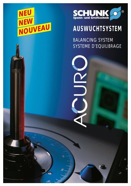
<strong>NEU</strong><strong>NEW</strong><strong>NOUVEAU</strong><strong>AUSWUCHTSYSTEM</strong>BALANCING SYSTEMSYSTEME D’EQUILIBRAGE
■eine Wucht!von SCHUNK■from SCHUNK■de SCHUNKéquilibrez vos dépenses!Durch die langjährige Erfahrung in derEntwicklung und Herstellung von Präzisionswerkzeughalternbefasst sich SCHUNK kontinuierlichmit den neuesten Trends derZerspanung. Dominierendes Thema: die HSC-Bearbeitung.Hersteller und Anwender von Spindeln, Werkzeughalternund Werkzeugen interessierensich deshalb für das genaue Auswuchten dieserSysteme – an die Wuchtqualität werdenheute höhere Anforderungen gestellt.Due to the many years of experience inR & D and in manufacturing precision toolholders,SCHUNK is continously endeavouringto modify to comply with the latest trendsand changes in the cutting tool industry.Whereby the manufacturers and users ofspindles, toolholders and tools are especiallyinterested in precisely balancing the systems.Today’s requirements to the balancing qualityof the individual components are totallydifferent.De par sa longue expérience de la conceptionet de la fabrication d’outils de hauteprécision, SCHUNK s’intéresse de très prèsaux développements technologiques dansle domaine de l’usinage avec enlèvementde copeaux et en particulier de l’usinageHSC. Dans ce domaine, fabricants et utilisateursde broches, de porte-outils et d’outils seréunissent autour d’un même problème, celuide leur équilibrage.2
■ SCHUNK entschied sich deshalb, ein geeignetesAuswuchtsystem anzubieten, das dieErschließung der HSC-Zerspanung ermöglichtund die Kunden begeistert.Moderne Werkzeugmaschinen mit hochdynamischenSpindelantrieben benötigenfeingewuchtete Werkzeugaufnahmen, daschlecht bzw. ungewuchtete WerkzeughalterToleranzen nicht einhalten, schlechteOberflächenqualitäten bieten, die Spindellagerungbelasten und auf Dauer sogar dieBeschädigung der Spindel verursachen.SCHUNK hat die Lösung:Das komplette System, Werkzeugaufnahmeund Schneidwerkzeug, als Einheit auszuwuchten.feinwuchtet IhrZerspanungssystem schnell, praxisgerechtund mit höchster Präzision auf geringste Restunwucht.Der Preis? Fair.■ For this reason, SCHUNK came to thedecision, to offer a suitable balancing systemin addition to the precision toolholders, andtherefore to cover the tools range of HighSpeed Cutting operations.For applications on modern machine toolswith high dynamic spindle operations it becomesmore and more important to use finebalanced toolholders. At increased spindleRPM badly or unbalanced toolholders causeproblems to the spindle mounting and thereforelower the life of the cutting tool or evendamage the spindle.SCHUNK has the solution:A complete system, tool mounting and cuttingtool, balanced as one unit.balances your cutting system, faster, at lowcost and with highest precision at a very lowresidual out of balance force.And the price? Fair.■ C’est pour y répondre et proposer à sesclients des systèmes HSC que SCHUNK a prisla décision de développer, parallèlement à sesporte-outils haute précision également unsystème d’équilibrage approprié.L’utilisation de machines-outils avec commandesde broches ultra-dynamiques nécessiteplus que jamais l’usage de raccordementsd’outils équilibrés avec précision. Des raccordementsd’outils mal voir pas du toutéquilibrés fatiguent la broche beaucoupplus rapidement d’où une usure prématuréevoire des dommages sérieux de la broche.SCHUNK à la solution pour équilibrer l’ensembleporte-util plus outil.vous permet d’équilibrervotre porte-outil rapidement avec uneprécision maximale pour un balourd résiduelminimal.Le prix? Vous serez surpris.SCHUNK BIETET MEHR!SCHUNK OFFERS MORE!SCHUNK VOUS EN OFFRE PLUS!3
■ Was ist Unwucht?● Statische UnwuchtSchwerpunkt eines Rotors liegtaußerhalb der Drehachse● MomentenunwuchtSchwerpunkt liegt auf derDrehachse● Dynamische UnwuchtKombination aus statischer undMomentenunwucht■ What is unbalanced?● Statically unbalancedThe center of gravity of a rotor islocated outside the rotating axis● Unbalanced momentumThe center of gravity is located on therotating axis● Dynamically unbalancedcombination of the two above■ Qu’est-ce qu’un défautd’équilibrage?● Déséquilibrage statiquele centre de gravité du rotor n’est passur l’axe de rotation● Déséquilibrage des momentsle centre de gravité se situe sur laxe derotation● Déséquilibrage dynamiquecombinaison de deséquilibtage statiqueet des moments■ Was verursachtUnwucht?● Unsymmetrische Form desWerkzeughalters● Unsymmetrische Form des Werkzeuges● Fertigungstoleranzen (Rundlauffehler)● Spindelrundlauffehler■ What causes theunbalanced forces?● Unsymmetrical shape of the toolholder● Unsymmetrical shape of the tools● Manufacturing tolerances(eccentric running)● Eccentric running of the spindle■ Quelles sont les causes possiblesdu déséquilibrage?● Le porte-outil n’est pas symétrique● L’outil n’est pas symétrique● Défaut de concentricité(usinage hors tolérances)● Défaut de concentricité de la broche■ Unwucht und IhreFolgen!● Schwingungen am Werkzeughalter● Reduzierung der Spindellebensdauer● Lagerschäden an der Maschinenspindel● Einschränkung derSchnittgeschwindigkeiten● Vibrationen verschlechtern dieOberflächengüte● Fertigungsgenauigkeit nimmt ab● Standzeitverkürzung derWerkzeugschneiden■ Unbalanced forces andthe results!● Vibrations at the toolholder● Reduction of spindle life● Damage to the bearings of the machinespindle● Reduced cutting speeds● Vibrations worsen the surface quality● The manufacturing accuracy reduces● Increased wear of the cutting tool■ Quelles sont lesconséquences possibles dudéséquilibrage!● Vibrations au niveau du porte-outil● Usure accélérée de la broche● Dommages sur les paliers de la brochede la machine● Diminution de la vitesse d’usinage● Mauvaise qualité de surface due auxvibrations● Moins bonne précision d’usinage● Réduction de la durabilité des tranchantsd’outils4
■ Intelligente AuswuchttechnikDie VorteileSoftware● Auswuchten wahlweise in einer oderzwei Ebenen (Seite 10)● PC-Steuerung mit kompletterAuswuchtsoftware● Unwuchtausgleich durch Bohren, Fräsenund Drehringe (Seite 10)● Werkzeugdatenverwaltung bis zu5000 Werkzeuge (Seite 10)● Einfachste Bedienung durch übersichtlicheMenüführung (Seite 10 – 11)● Kalibrierfunktion für Maschine undWerkzeug● Verschiedene Messverfahren auswählbar(Seite 11)● Fehlerdiagnose für Funktionsprüfungder Maschine● Dichtefunktion (Seite 9)● Sehr gutes Preis-/Leistungsverhältnis● Einfach umstellbar auf andere Sprachen● Graphische Anzeige der Unwucht imPolardiagramm (Seite 11)Hardware● Hochgenaues Adaptersystem mit automatischerSpannung für alle gängigenWerkzeugaufnahmen (Seite 6)● Hohe Mess- und Wiederholgenauigkeitdurch praxisgleiches Aufnehmen undSpannen der Werkzeugaufnahmen(Seite 6)● Optische Eindrehhilfe (Seite 9)● Kraftmessende Vertikal-Wuchtmaschine● Lasermarkierung (Seite 8)■ The intelligent way ofbalancingThe AdvantagesSoftware● Balancing optionally, in one or twoplanes (Page 10)● PC-controlled with complete balancingsoftware● Adjustment of unbalance caused duringdrilling, milling and the use of turningrings (Page 10)● Data administration of up to 5.000 tools(Page 10)● Easy handling due to the menu-drivensystem (Pages 10 – 11)● Calibration function for machine and tools● Different measuring methods can bechosen (Page 11)● Trouble shooting for machine functioncontrol● Control of density (Page 9)● Excellent cost-performance ratio● Easily adjustable onto other computerlanguages● Graphic display of unbalancing on thepolar diagram (Page 11)Hardware● Precise adaptor system with automaticclamping for popular toolholders (Page 6)● High measuring accuracy and repeatabilitydue to realistic simulation of toolmounting and clamping (Page 6)● Optical insertion aid (Page 9)● Force-measuring vertical balancingmachine● Laser marking (Page 8)■ L’équilibrage intelligentLes avantagesLe logiciel (Software)● Equilibrage d’un ou 2 plans au choix(page 10)● Logiciel complet pour ordinateur● Rectification du déséquilibrage parperçage, fraisage ou bagues (page 10)● Gestion des données relatives à plusde 5000 outils (page 10)● Utilisation simple par menus(pages 10 et 11)● Calibrage de la machine et de l’outil● Différents principes de mesure au choix(page 11)● Diagnostique des pannes et contrôle dubon fonctionnement de la machine● Fonction «densité» (page 9)● Excellent rapport qualité-prix● Passage facile d’une langue à une autre● Représentation graphique des défautsd’équilibrage (diagr. polaire, page 11)Matériel (Hardware)● Système d’adaptation haute précision avecserrage automatique de tous les typeshabituels de raccordements d’outils (p. 6)● Haute précision de mesure et de répétitiongrâce au fait que les logements etle serrage des raccordements d’outilssoient semblables à ceux utilisés lors del’usinage (page 6)● Guidage optique du début de tournage(page 9)● Machine d’équilibrage vertical quimesure aussi les forces● Marquage laser (page 8)5
■ Automatisches SpannsystemÜber eine elektropneumatische Steuerung wird ein praxisnahes Einziehenwie in der Maschinenspindel simuliert.Weitere wichtige Merkmale sind:● Auswuchtmeßspindel mit 360° Skalierung● Konstante Einzugskräfte● Kein aufwendiger manueller Spannvorgang● Keine unterschiedlichen Anzugskräfte wie beim manuellen Spannvorgang● Absolut zentrischer Werkzeugeinzug■ Automatic Clamping SystemVia an electro-pneumatic control unit, the operation of a machinespindle is simulated.Some more characteristics:● Measuring spindle for balancing with a 360° scale● Constant feeding forces● Easy manual clamping operation● Compared with a manual clamping operation no various starting forces● Absolutely concentric tool insertion■ Dispositif automatique de serrageLa commande électropneumatique active unsystème de serrage semblable à celui des brochesde machines-outils.Les autres points importants du système sont:● Broche de mesure de déséquilibrge graduéesur 360°● Forces de serrages constantes● Pas de serrage manuel● Des forces de serrages homogènes contrairementau cas d’un serrage manuel● Centrage précis de l’outil lors du serrage6
Zubehör Accessories Accessoires■ Aufnahmeadapter● Alle wichtigen Schnittstellen erhältlich(<strong>SK</strong>, H<strong>SK</strong>, ...)● Rüstzeit bei Adapterwechselkleiner 5 min.● Direktspannung –keine Zwischenadapter notwendig⇒ dadurch hohe Spanngenauigkeitund bestes Wuchtergebnis■ Mounting Adaptor● All popular tool mountings are available(<strong>SK</strong>, H<strong>SK</strong>, ...)● The changing time for adaptors isless than 5 minutes● Direct clamping –no intermediate adaptors are necessary⇒ therefore a high clamping accuracyand best balancing results are achieved■ Adaptateur de raccordement● Toutes les interfaces sont disponibles(<strong>SK</strong>, H<strong>SK</strong> etc.)● Changement d’adaptateur en moins de5 minutes● Serrage direct –sans adaptateur intermédiare⇒ d’oú une grande précision deserrage et un meilleur équilibrageAdapterAdaptorAdaptateurH<strong>SK</strong> 32H<strong>SK</strong> 40H<strong>SK</strong> 50H<strong>SK</strong> 63H<strong>SK</strong> 80H<strong>SK</strong> 100Ident-Nr.Id.-no.RéférenceAdapterAdaptorAdaptateur<strong>SK</strong> 30 ohne Spannsystem / <strong>SK</strong> 30 without clamping system / <strong>SK</strong> 30 sans système de serrage<strong>SK</strong> 30 mit Spannsystem für Gewinde M12 / <strong>SK</strong> 30 with clamping system for thread M12 / <strong>SK</strong> 30 avec système de serrage pour filetage M12<strong>SK</strong> 30 mit Spannsystem für Anzugsbolzen / <strong>SK</strong> 30 with clamping system for retention knop / <strong>SK</strong> 30 avec system de serrage pour tirette de serrage<strong>SK</strong> 40 ohne Spannsystem / <strong>SK</strong> 40 without clamping system / <strong>SK</strong> 40 sans système de serrage<strong>SK</strong> 40 mit Spannsystem für Gewinde M16 / <strong>SK</strong> 40 with clamping system for thread M16 / <strong>SK</strong> 40 avec système de serrage pour filetage M16<strong>SK</strong> 40 mit Spannsystem für Anzugsbolzen / <strong>SK</strong> 40 with clamping system for retention knop / <strong>SK</strong> 40 avec system de serrage pour tirette de serrage<strong>SK</strong> 50 ohne Spannsystem / <strong>SK</strong> 50 without clamping system / <strong>SK</strong> 50 sans système de serrage<strong>SK</strong> 50 mit Spannsystem für Gewinde M24 / <strong>SK</strong> 50 with clamping system for thread M24 / <strong>SK</strong> 50 avec système de serrage pour filetage M24<strong>SK</strong> 50 mit Spannsystem für Anzugsbolzen / <strong>SK</strong> 50 with clamping system for retention knop / <strong>SK</strong> 50 avec system de serrage pour tirette de serrageIdent-Nr.Id.-no.Référence207 001207 002207 003207 004207 005207 006207 007207 008207 009207 010207 011207 012207 013207 014207 0157
■ LasermarkierungFür die genaue optische Markierung derUnwuchtposition am Werkzeug.● Genaue Positionsanzeige überLeuchtstärke des Lasers■ Laser MarkingFor an exact optical marking of theunbalance position at the tool.● Exact indication of position via lightintensity of the laser■ Marquage laserPour un marquage précis dudéséquilibrage sur l’outil.● Affichage précis de la position parl’intermédiaire de la luminosité du laserIdent-Nr. / Id.-no. / Référence 207 016■ EichmeisterZur Kalibrierung der Wuchtmaschinebestehend aus Positionierhülse undKalibriergewicht.● Einfache Kalibrierung derGesamtmaschine über Kalibriermenü■ Calibration UnitFor calibration of the balancing machineconsisting of a positioning sleeve and astandard weight.● Easy calibration of the total machine viacalibration menu■ EtalonPour le calibrage de l’équilibreuse.Il comprend une douille de positionnementet un poids de calibrage.● Calibrage simple de la machine guidépar menusIdent-Nr. / Id.-no. / Référence 207 0178
Zubehör Accessories Accessoires■ Optische EindrehhilfeInkrementale Winkelmessung derAuswuchtmessspindel mit aktuellerAnzeige.⇒ Schnelles ermitteln der Winkellage derUnwucht am Rotor durch farbliche Kennzeichnungam Bildschirm (siehe Seite 10)■ WerkbankIdent-Nr. 207018Die stabile Ausführung garantiert derMaschine einen sicheren Stand undwirkt über Ihre große Masse zusätzlichschwingungsdämpfend.● Mit Rollenschublade und Flügeltüre● Maße B x H x T:1500 x 850 x 700 mmIdent-Nr. 207019■ DichtefunktionSoftware-Ergänzung zum Bohren undFräsen von verschiedenen Materialienmit unterschiedlicher Dichte.Ident-Nr. 207020■ FräsprogrammSoftware-Ergänzung zum Ausgleichender Unwucht durch Fräsen.Ident-Nr. 207021■ KalbriermagneteZum einfachen und schnellen Kalibrierender Werkzeuge oder Funktionsprüfungder Maschine.Ident-Nr. 207022■ SpannungswandlerZusatztransformator für andereSpannungen.Ident-Nr. 207023■ Optical insertion aidIncremental angular measuring ofthe balancing measuring spindle withdisplay.⇒ Fast finding of the angular position ofunbalance at the rotor due to colouredmarking at the screen (see page 10)■ Work BenchId.-no. 207018The stable design ensures a safe andergonomic working position and, due toits mass is shock-absorbing.● With drawers and wing door● Dimensions W x H x D:1500 x 850 x 700 mmId.-no. 207019■ Density functionAdditional software for boring anddrilling of various materials.Id.-no. 207020■ Milling ProgrammeAdditional software for compensation ofunbalance by milling operation.Id.-no. 207021■ Calibration magnetsFor easy and fast calibration of tools orcontrol of function of the machine.Id.-no. 207022■ Voltage TransformerAdditional transformer for other voltages.Id.-no. 207023■ Guidage optique du débutde tournageMesure angulaire incrémentielle del’équilibrage de la broche, avec affichagede la valeur actuelle.⇒ L’angle de déséquilibrage du rotorest repéré rapidement par un marquagecouleur à l’écran (voir en page 10)■ L’établiRéférence 207018Particulièrerement stable, la machine, depar son poids important, absorbe aussiles vibrations.● Tiroirs à roulettes et portes replisables● largeur x hauteur x profondeur:1500 x 850 x 700 mmRéférence 207019■ La fonction «densité»Complément de logiciel pour les perçageet fraisage de matériaux de différentesdensités.Référence 207020■ Le programme de fraisageComplément de logiciel pour lerééquilibrage par fraisage.Référence 207021■ Les aimants de calibragePour le calibrage simple et rapided’outils ou le contrôle du bonfonctionnement de la machine.Référence 207022■ Le transformateurTransformateur supplémentaire pourd’autres valeurs de tension.Référence 2070239
■ ÜbersichtlicheBedienerführung– alles auf einen Blick!■ Detailed operation facility– At a glance!■ Interface utilisateurparticulièrement simple –vue d’ensemble d’un seulcoup d’œil!■ 5000 Werkzeugspeicherplätze■ 5.000 tools can be stored■ Potentiel mémoire pour 5000 outils■ Eingabe der Werkzeugparameter in den Wuchtebenen■ Input of the tool parameter at the balancing planes■ Saisie des paramètres de l’outil dans les différents plans d’équilibrage■ Optische Eindrehhilfe zum schnellen Auffinden der Auswuchtposition (Option)■ Optical screw-in aid for a quick finding of where to set the balancing bores (on option)■ Guidage optique du début de tournage pour une meilleure reconnaissance du point dedéséquilibre (en option)10
■ Auswuchtverfahren in 1 oder 2 Ebenen■ Balancing operation in 1 or 2 planes■ Rééquilibrage sur un ou 2 plans■ Eingabe der Wuchttoleranz inWuchtgüten (Q oder G)■ Input of the balancing tolerance inbalancing qualities (Q or G)■ Saisie de la tolérance de rééquilibrage(niveau de qualité Q ou G)■ Graphische und numerische Anzeige der Unwucht■ Graphic and numerical display of unbalancing■ Affichage numérique et graphique du déséquilibrage■ Wuchtausgleich durch Bohren,Fräsen oder über Drehringe■ Balance compensation by drilling,milling or via turning rings■ Rectification du déséquilibragepar perçage, fraisage ou bagues■ Verschiedene Messverfahren auswählbar■ Choose between varoius measuring procedures■ Différentes méthodes de mesure au choix11
■ Technische DatenAuswuchtsystem■ Technical DataBalancing System■ Données techniquesSystem d’equilibragemax. Werkzeuglänge350 mm max. tool length350 mm Longueur d’outil max.350 mmmax. Werkzeug-Ø300 mm max. tool diameter300 mm Diam. d’outil max.300 mmmax. Werkzeuggewicht20 kg max. tool weight20 kg Mass d’outil max.20 kgAbmessungenBxHxT 400x690x580mm Dimensions W x H x D 400 x 690 x 580 mm Dimensions L xHxP 400x690x580mm(ohne PC)Gewicht (ohne PC)ca. 100 kg(without PC)Weight (without PC)ca. 100 kg(sans PC)Masse (sans PC)environ 100 kgSpindeldrehzahl1200 1/min Spindle speed1200 1/min Vitesse de rotation de la broche 1200 1/minMessgenauigkeit < 0.5 gmm pro Messebene Measuring accuracy < 0.5 gmm per plane Précision de mesure< 0.5 gmmStromversorgung 200 - 240 V, 50 - 60 Hz Power requirements 200 - 240 V, 50 - 60 Hz Alimentation électrique 200 - 240 V, 50 - 60 Hz(andere Spannungen auf Anfrage)Leistungsaufnahmeca. 0.5 kW(other supplies upon request)Power usageca. 0.5 kW(autres tensions sur demand)Consommation d’énergie environ 0.5 kWDruckluft8 bar Compressed air8 bar Air comprimé8 bar(nur bei Ausführung mit Spannsystemen)(only for versions with clamping system)(uniquement pour des versions avec systèmes de serrage)Ident-Nr. 207000 Id.-no. 207000 Référence 207000■ Unwuchteinflüsse aufMaschinenspindeln, Werkzeugaufnahmenund WerkzeugeDie UnwuchtEine Unwucht erzeugt bei der sich drehenden Spindeleine Fliehkraft, die die Laufruhe des Werkzeugs stört.Diese Unwucht hat Einfluß auf den Arbeitsprozeß unddie Lebensdauer des Spindellagers.Die Fliehkraft F wächst linear mit der Unwucht U undquadratisch mit der Drehzahl nach untenstehenderFormel.F = U · 2 F = U · 2AuswuchtenUm unerwünschte Fliehkräfte auszugleichen, muß diesymmetrische Massenverteilung wiederhergestellt werden,mit dem Ziel, daß auf die Spindellagerung keineFliehkräfte wirken. Bei Werkzeugaufnahmen sind Ausgleichsbohrungenoder -flächen üblich. Dadurch tendiertdie Summe aller auf die Achse wirkenden Fliehkräftegegen Null (siehe DIN ISO 1940).SchwerpunktverlagerungDurch die Unwucht einer Welle wird deren Schwerpunktaus der Drehachse um einen Abstand in Richtung derUnwucht verlagert. Dieser Abstand wird auch Restexzentrizitäte oder Schwerpunktverlagerung genannt.Je größer die Wuchtkörpermasse m ist, desto größerkann die zulässige Restunwucht U sein.e = U m■ Effect of imbalance on spindles,tool holders and toolsImbalanceAn imbalance produces a centrifugal force at the rotatingspindle impeding the smooth running of the tool.This imbalance influences the working process and thelife span of the spindle bearings.The centrifugal force F increases linear with the imbalanceU and squared with the number of revolutionsaccording to the formula below.Counter balancingTo compensate unwanted centrifugal forces, the symmetricaldistribution of mass must be restored with theaim of eliminating any centrifugal forces influencingthe spindle bearing. Tool holders generally havecompensating holes or areas which assist in directingthe total amount of all centrifugal forces influencingthe axis towards zero (see DIN ISO 1940).Eccentricity of gravity centerThe imbalance of a spindle causes its center of gravityto deviate a certain distance from the rotating axis indirection of the imbalance. This distance is called resteccentricitye or eccentricity of center of gravity. Theheavier the weight of the body mass m, the greater therest-imbalance U permissible.e = U m■ Influence du balourd sur lesbroches, les portes outils et lesoutilsLe balourdUn balourd engendre une force centrifuge sur la brocheen rotation qui pertube la rotation de l’outil. Ce balourdinflue sur le processus de travail et sur la durée de viedu roulement de broche.La force centrifuge F croit linéairement avec le balourdU et au carré avec la vitesse de rotation d’après laformule ci-dessous.F = U · 2L’équilibragePour compenser des forces centrifuges génantes, il fautrétablir une parfaite répartition des masses dans le butd’éviter que des forces centrifuges ne s’exercent sur lespaliers de broche. Pour cela, on enlève de la matièresur les portes outils. Ainsi la somme de toutes lesforces centrifuge agissants sur l’axe tendent vers zéro(voir DIN ISO 1940).Déplacement du centre de gravitéLe balourd d’un arbre décale son centre de gravité versce balourd. Ce décalage se nomme également excentricitérésiduelle ou déplacement du centre de gravité.Plus la masse du corps m est importante, plus lebalourd résiduel acceptable U pourra être important.e = U mFliehkraft / Centrifugal force / Force centrifugeUnwucht / Imbalance /BalourdFliehkraft / Centrifugal force / Force centrifugeAusgleichsbohrung /Compensation hole /Alésage d’équilibrageUnwucht / Imbalance /BalourdRestrexzentrizitätRest eccentricityExcentricité résiduelleAusgleichsbohrung /Compensation hole / Alésaged’équilibrageUnwucht / Imbalance /BalourdSchwerpunkt / Center of gravity/ Centre de gravitéDrehachse / Rotatingaxis / Axe de rotationDrehzahl / Revolutions / Vitesse de rotation Drehzahl / Revolutions / Vitesse de rotation Drehzahl / Revolutions / Vitesse de rotation12
WuchtgrenzenZiel des Auswuchtens muß es sein, einen Kompromißzwischen dem technisch Machbaren und dem wirtschaftlichSinnvollen zu finden. Es ist z.B. widersinnig,ein Hydraulik-Dehnspannfutter mit H<strong>SK</strong> auf G1.0 zuwuchten, wenn es im Einsatzfall auf der Maschine miteinem Rundlauffehler gespannt wird, der eine um einVielfaches höhere Unwucht erzeugt.Beispiel:Masse mit gespanntem Fräser m = 1.340 kgBetriebsdrehzahl n = 30 000U/min.Geforderte Wuchtgüte G1Max. Restexzentrizität e zul = 0.318 µmMax. UnwuchtU = 0.427 gmmUnwucht durch Rundlauffehlerzwischen Spindel und Futter r = 2 µmErzeugte UnwuchtU = 2.68 gmm■ UnwuchtberechnungDie Unwucht ist ein Maß, das angibt, wieviel unsymmetrischverteilte Masse in radialer Richtung von derDrehachse entfernt ist. Die Unwucht wird in gmm angegeben.Das Abstandmaß e sagt aus, wie weit derSchwerpunkt eines Teils von der Drehachse entfernt ist.Die Unwucht ergibt sich aus:darin ist:U = Unwucht in gmme = Schwerpunktabstand in µmm = Masse in kgDa der Abstand in der Regel unbekannt ist, wird die UnwuchtU ist auf einer Wuchtmaschine ermittelt und mitHilfe von Abtragungen an einem definierten Ausgleichsradiusauf annähernd U null minimiert. Das zulässigeAbstandsmaß e ergibt sich aus den Kundenanforderungen.Durch e zul kann etwa abgeschätzt werden, wieschwierig das Auswuchten sein wird. Die zulässigeRestmasse m R errechnet sich mit der Formel:darin ist:r = Ausgleichsradius in mm(der Ausgleichsradius ist der Radius, in denbeim Wuchten gebohrt wird)m = Masse in kge zul = zul. Abstandsmaß in µm bzw.g · m= Restmasse in gkgm RU = m · em R= ezul · mrBeispiel:Bei einem zulässigen Abstandsmaß von e zul = 4.01µm, das entspricht G6.3 bei 15 000 U/min., einemFuttergewicht (z.B. Hydraulik-Dehnspannfutter Ident-Nr. 204 054, d.h. H<strong>SK</strong>-A 63, Spann-Ø 12) vonm = 1.125 kg und einem Ausgleichsradius von r = ca.25 mm (Bohren bei d4) ergibt sich für die max.zulässige Ausgleichsmasse m R :Balancing limitsThe aim of balancing must be to find a compromisebetween technical feasibility and economic logic. Forexample, it is illogical to balance a H<strong>SK</strong> hydraulicexpansion chuck on G1.0, if in individual applicationsit is clamped in a machine with concentricity errorsproducing a much higher imbalance.Example:Mass in clamped milling cutter m = 1.340 kgOperating speed n = 30 000rev./min.Required balance grade G1Max. rest eccentricity e acc = 0.318 µmMax. imbalanceU = 0.427 gmmImbalance through error in concentricitybetween spindle and chuck r = 2 µmProduced imbalance U = 2.68 gmm■ Calculating imbalanceImbalance is a measure, specifying how much unsymmetricaldistributed mass deviates radially from therotating axis. Imbalance is measured in gmm. Themeasure of distance e determines the distance of thecenter of gravity of an element to the rotating axis.Imbalance is calculated as follows:U = m · ewhereby:U = imbalance in gmme = eccentricity of center of gravity in µmm = mass in kgAs the distance e is generally unknown, the imbalanceU is is calculated on a balancing machine and minimisedto approx. U zero with the help of reductions at a definedcompensation radius. The acceptable measure ofdistance e is determined by customer requirements.Through e acc , the difficulties of balancing can be gaugedapproximately. The acceptable rest-mass m R is calculatedwith the formula:m R= eacc · mrwhereby:r = compensation radius in mm(the compensation radius is the radius ofdrilling when balancing)m = mass in kge acc = accept. measure of distance in µm org · mm R = rest mass in gkgExample:With an accept. measure of distance of e acc = 4.01 µm,which corresponds to G6.3 at 15 000 rev./min., achuck weight (e.g. hydr. expansion chuck Id.-No.204 054 i.e. H<strong>SK</strong>-A 63, clamping-Ø 12) of m =1.125 kg and a compensation radius of r = approx.25 mm (drilling at d4) the max. acceptable compensationmass m R is calculated as follows:Limites d’équilibrageLe but de l’équilibrage est de trouver le bon compromisentre ce qui est réalisable techniquement et ce qui estéconomiquement raisonnable.Il est, par exemple, absurde d’équilibrer un mandrinexpansible hydraulique H<strong>SK</strong> à une qualité G1.0 si lemandrin est monté sur une machine qui génère unbalourd important.Exemple:Masse avec fraise montée m = 1.340 kgVitesse de rotation d’usinage n = 30 000tr./min.Qualité d’équilibrage demandée G 1Excentricité résiduelle max. e acc = 0.318 µmBalourd max.U = 0.427 gmmBalourd occasionné par le défaut de concentricité entrela broche et le mandrin r = 2 µmBalourd résultantU = 2.68 gmm■ Calcul du balourdLe balourd est une unité qui donne les masses répartiesassymétriquement déviant radialement par rapport àl’axe. Le balourd s’exprime en gmm. L’unité dedistance e exprime la distance du centre de gravitéd’une pièce par rapport à l’axe de rotation. Lebalourd résulte de:avec:U = balourd en gmme = excentricité du centre de gravité en µmm = masse en kgComme en général l’excentricité e n’est pas connue, lebalourd U zero est déterminé sur une machine à équilibreret il est réduit à l’aide de perçages dans un rayonde compensation.L’excentricité admise est déterminée par le client. Al’aide de e acc on peut juger approximativement des difficultésque représentent l’équilibrage. La masse résiduellem R admise se calcule d’après la formule:avec:r = rayon de compensation en mm (le rayon decompensation est le rayon dans lequel sontréalisés les perçages)m = masse en kge acc = distance acceptable en µm oug · m= masse résiduelle en gkgm RU = m · em R= eacc · mrExemple:Avec une distance acceptable de e acc = 4.01 µmcorrespondant à G6.3 à 15 000 tr./min., un poids dem = 1.125 kg (p. e. pour un mandrin expansibleréf. 204 054, H<strong>SK</strong>-A 63, diamètre de serrage 12)et un rayon de compensation de r = env. 25 mm(perçage à d4) il résulte la masse résiduelle max. m Rsuivante:m R= 4.01 µm · 1.125 kg = 0.180 g25 mmm R= 4.01 µm · 1.125 kg = 0.180 g25 mmm R= 4.01 µm · 1.125 kg = 0.180 g25 mm13
Formeln und Kurzzeichen / Formulas and symbols / Formules et symbolesG G = e · Wuchtgüte / Balance grade / Qualité d’équilibragem [g] Masse / Mass / Massem R [g] Unsymmetrische Masse / Unsymmetrical mass / Masse assymétriquer [mm]Abstand m R zur Drehachse / Distance between m R and rotating axis /Distance entre mg et axe de rotationn [1/min] Drehzahl / Revolutions / Vitesse de rotatione[µm]e = U mSchwerpunktabstand / Eccentricity of center of gravity /Excentricité au centre de gravité [1/sec] = 2 · · n Winkelgeschwindigkeit / Angular velocity / Vitesse angulaireU [gmm] U = m R · r = m · e Unwucht / Imbalance / BalourdF [N] F = U · 2 Fliehkraft / Centrifugal force / Force centrifugeDie Restunwucht e läßt sich aus der gewünschten Qualitätsstufe G und errechnen, es gilt:The rest-imbalance e is calculated acc. to the desired quality grade G and , the following applies:Le balourd résiduel e peut se calculer à l’aide de G et :e = G = U mSchwerpunktabstand ezur Drehachse /Eccentricity of center ofgravity e to the rotating axis /Excentricité au centre degravité e et l’axe de rotationWuchtbohrung /Balancing hole /Alésage d’équilibrageDrehachse /Rotating axis /Axe de rotation■ Berechnung der Gesamtwuchtgütedes kompletten Systems:Spindel · Werkzeugaufnahme · Werkzeug■ Calculation of the total balancinggrade of the assembled system:Spindle · Tool holder · Tool■ Calcul de la qualité d’équilibragetotal du système complet:Broche · Porte outil · OutilDarstellung der Gesamtwuchtgüte / Illustration of balancinggrade total / Illustration de l’équilibrage totaltot.tot.SpindleBrocheBeispiel / Example / ExempleU ges. = U Spindel + U Werkzeug-+aufnahmeTool holderPorte outilWerkzeugToolOutilUges. = USpindel (G0.4) + UWkz.Aufnah. (G2.5) + UWkz. (G6.3)Berechnung der Restunwucht / Calculation of eccentricity /Calcul du balourd résiduelU = Q · 60 · m2 · π · nUSpindelSpindleBrocheUAufnahmeTool holderAttachmentUWerkzeugToolOutilUmrechnung der Wuchtgüte des Gesamtsystems /Balancing grade conversion of the total system /Conversion de la qualité d’équilibrage du système completQ = Uges. · 2 · π · n60 · mges.m in gU in gmm= 0.4 · 60 · 15000 = 1.9102 · π · 30000= 2.5 · 60 · 1125 = 0.8952 · π · 30000= 6.3 · 60 · 215 = 0.4312 · π · 30000mges. in g: 16340Uges. in gmm: 3.236Beispiel / Example / Example130000 ·Q = 3.236 gmm · 2 · π · min = 0.6260 s · 16340 gMaschinenspindelmit 4-Punkt-SpannerSpindle with4-point tensionBroche de machineavec serrage 4 points2.25 gmm2 µmHydro-DehnspannfutterHydraulic chuckMandrin hydraulic0.65 gmm3 µmGesenkfräserCountersinkFraise à matriceSumme des GesamtsystemsSum of total systemSomme de l’assemblage completGGG2520G1510512520151052520151052520151052.5Spindel – Wuchtgüterotierender Teile1.00.80.60.40.2WerkzeugaufnahmeExzentrizität 2 µmWerkzeugExzentrizität 3 µmGesamtwuchtgüten = 30 000 1/min11 2.5 6.3Spindle - Balancinggrade of rotating partsTool holdereccentricity 2 µmToolEccentricity 3 µm162.5Balancing grade totaln = 30 000 1/minBroche - Qualité d’équilibragedes pièces en rotationPorte outilexcentricité 2 µmOutilExcentricité 3 µmQualité d’équilibrage totalen = 30 000 1/min2520.47 0.65 0.57 0.75 0.81 0.831.48 1.50 1.55 1.681.50.88 1.0110.50.450.520.550.620.46.31614
Abb.: Auswucht-Gütestufen für starre Wuchtkörper nach VDI 2060. Zulässige, auf die Wuchtkörpermassebezogene Restunwuchten für verschiedene Gütestufen G in Abhängigkeit von derhöchsten Betriebsdrehzahl des Wuchtkörpers.Quality levels of counterbalance for stiff balancing bodies (VDI 2060). Admissible unbalance withregard to the mass of the balancing body for different quality levels G depending on the highestrotational speed of the balancing body.Qualité d’équilibrage pour corps à équilibrer rigides (VDI 2060). Balourd résiduel admissible pourdifférentes qualités d’équilibrage G en fonction de la vitesse de rotation maximale du corps àéquilibrer.Zulässige Restunwucht/Wuchtkörpermasse in g mm/kg (bzw.e in µm*)Admissible unbalance/mass of the balancing body in g mm/kg (e in µm*)Balourd résiduel admissible/masse du corps à équilibrer en gm/kg (e en µm*)*Für starre Wuchtkörper mit zwei Ausgleichsebenen gilt im allgemeinen je Ebene die Hälftedes betreffenden Richtwertes, für scheibenförmige, starre Wuchtkörper gilt der volle Richtwert* For stiff balancing bodies with two compensating levels, 50% of the standard value are validfor each level. For stiff, disk shaped balancing bodies, the whole standard value applies*Pour les corps à équilibrer rigides avec 2 plans de compensation, on prend en général le moitiéde la valeur indicative par plan, pour ceux à disque, on prend la totalité de la valeur indicativeMaximale Betriebsdrehzahl in U/min / Maximum operating speed in rpm / Vitesse de rotation tout maximale en rpm8063504031.525201612.51086.3543.152.521.61.2510.80.630.50.40.3150.250.20.160.1250.10.080.0630.050.04300Q 16Q 6.3Q 2.5Q 1Q 0.4600 950 1500 3000 6000 9500 15000 30000 60000 95000Maximale Betriebsdrehzahl in U/s / Maximum operating speed in rps / Vitesse de rotation tout maximale en rps5 10 16 25 50 100 160 250 500 1000 1600■ WuchtempfehlungenDerzeit wird im Rahmen des Arbeitskreises Wuchtenbei der Deutschen Arbeitsgemeinschaft IndustrielleForschung eine Vorlage zur Empfehlung für das wirtschaftlicheWuchten erarbeitet.Die Firma SCHUNK wird bis zur Verabschiedung dieserRichtlinie aufgrund des derzeitigen Kenntnisstandesalle TENDO Dehnspannfutter standardmässig auf diefolgenden Wuchtgüten feinwuchten:■ Balancing recommendationsIn the ”Deutsche Arbeitsgemeinschaft IndustrielleForschung” a study group, covering the subject ofbalancing, is currently working on a submission dealingwith the economic recommendations for balancing.Up to the ratification of these guidelines and in accordancewith the current and latest information, SCHUNKwill balance its hydraulic chucks as standard accordingthe following balance qualities:■ Préconisations d’équilibrageUn groupe d’étude du «Deutsche ArbeitsgemeinschaftIndustrielle Forschung» travaille actuellement àl’élaboration des préconisations pour un équilibragerentable.La société SCHUNK va, jusqu’à adoption de cette norme,équilibrer tous les mandrins expansibles hydrauliquesTENDO, selon les connaissances techniques actuelles,aux qualités d’équilibrage suivantes:H<strong>SK</strong>-A 32-63H<strong>SK</strong>-A 80-100H<strong>SK</strong>-C 32-63H<strong>SK</strong>-C 80-100H<strong>SK</strong>-E 32-63<strong>SK</strong>-40 & 50G6.3 bei 15 000 U/minG6.3 bei 12 000 U/minG6.3 bei 15 000 U/minG6.3 bei 12 000 U/minG6.3 bei 30 000 U/minG6.3 bei 15 000 U/minH<strong>SK</strong>-A 32-63H<strong>SK</strong>-A 80-100H<strong>SK</strong>-C 32-63H<strong>SK</strong>-C 80-100H<strong>SK</strong>-E 32-63<strong>SK</strong>-40 & 50G6.3 to 15 000 rev./minG6.3 to 12 000 rev./minG6.3 to 15 000 rev./minG6.3 to 12 000 rev./minG6.3 to 30 000 rev./minG6.3 to 15 000 rev./minH<strong>SK</strong>-A 32-63H<strong>SK</strong>-A 80-100H<strong>SK</strong>-C 32-63H<strong>SK</strong>-C 80-100H<strong>SK</strong>-E 32-63<strong>SK</strong>-40 & 50G6.3 à 15 000 tr/minG6.3 à 12 000 tr/minG6.3 à 15 000 tr/minG6.3 à 12 000 tr/minG6.3 à 30 000 tr/minG6.3 à 15 000 tr/minDa die Drehzahl letztendlich den größten Einfluß hat,und auch von der Schnittstelle Spindel bzw. SpindellagerungGrenzen vorliegen, wurden im Rahmen derH<strong>SK</strong>-Normung folgende Grenzdrehzahlen für die H<strong>SK</strong>-Schnittstellen als Richtwerte empfohlen:Because rotational speed is the largest influencingfactor together with the limits regarding the spindle orspindle bearing interface, the following rpm limits forH<strong>SK</strong>-interfaces have been recommended as guidelineswithin the H<strong>SK</strong>-standards:Etant donné que la vitesse de rotation à la plus grandeincidence et que des limites sont fixées par la brocheet les roulements de broche les vitesses de rotationssuivantes ont été définies comme limites recommandéespour les normes H<strong>SK</strong>:H<strong>SK</strong>-A 32H<strong>SK</strong>-A 40H<strong>SK</strong>-A 50H<strong>SK</strong>-A 63H<strong>SK</strong>-A 80H<strong>SK</strong>-A 100bis 50 000 U/minbis 42 000 U/minbis 30 000 U/minbis 25 000 U/minbis 20 000 U/minbis 16 000 U/minH<strong>SK</strong>-A 32H<strong>SK</strong>-A 40H<strong>SK</strong>-A 50H<strong>SK</strong>-A 63H<strong>SK</strong>-A 80H<strong>SK</strong>-A 100up to 50 000 rev./minup to 42 000 rev./minup to 30 000 rev./minup to 25 000 rev./minup to 20 000 rev./minup to 16 000 rev./minH<strong>SK</strong>-A 32H<strong>SK</strong>-A 40H<strong>SK</strong>-A 50H<strong>SK</strong>-A 63H<strong>SK</strong>-A 80H<strong>SK</strong>-A 100jusqu’à 50 000 tr/minjusqu’à 42 000 tr/minjusqu’à 30 000 tr/minjusqu’à 25 000 tr/minjusqu’à 20 000 tr/minjusqu’à 16 000 tr/minAbhängig vom Werkzeug kann es bei diesen maximalenDrehzahlen notwendig sein, die Werkzeugaufnahmeund das Werkzeug gemeinsam zu wuchten.Klare Grenzwerte können nur unter Berücksichtigungder Maschinen- oder Spindelausführung und bei definiertenWerkzeugen mit Auskraglängen festgelegtDepending on the tool, it may be necessary to balanceboth tool holder and tool when applying these maximumrpm.Exact limits can only be determined if the machine andspindle manufacturers are taken into consideration andit is possible to define tools and projecting lengths.En fonction de l’outil, il est nécessaire, à ces vitessesde rotation élevées, d’équilibrer le porte outil équipé del’outil.Les limites précises ne peuvent être définies qu’entenant compte du type de machine ou de broche et dela longueur de l’outil.15


